

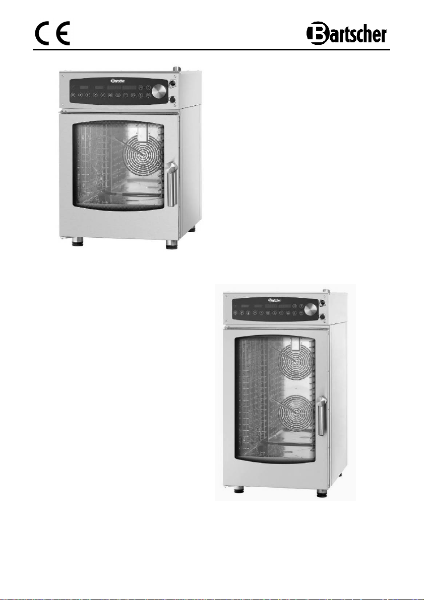
117261 / D6110 Digital
117201 / D10110 Digital
V1/0414
GB/UK
ENGLISH
Translation
of the original instruction manual
Read these instructions before using and keep
them available at all times!
1. General information .............................................................................................. 41
1.1 Information about the instruction manual ........................................................... 41
1.2 Key to symbols ................................................................................................... 41
1.3 Liability and Warrantees .................................................................................... 42
1.4 Copyright protection ........................................................................................... 42
1.5 Declaration of conformity ................................................................................... 42
2. Safety ...................................................................................................................... 43
2.1 General information ........................................................................................... 43
2.2 Safety instructions for use of the device ............................................................ 43
2.3 Intended use ...................................................................................................... 44
3. Transport, packaging and storage ....................................................................... 45
3.1 Delivery check .................................................................................................... 45
3.2 Packaging .......................................................................................................... 45
3.3 Storage .............................................................................................................. 45
4. Technical data ........................................................................................................ 46
4.1 Overview of parts ............................................................................................... 46
4.2 Technical specification ....................................................................................... 47
5. Installation .............................................................................................................. 50
5.1 General safety instructions................................................................................. 50
5.2 Setup ................................................................................................................. 51
5.3 Water connection ............................................................................................... 53
5.4 Drain connection ................................................................................................ 54
5.5 Electric connection ............................................................................................. 54
5.6 Start-up and commissioning............................................................................... 55
6. Operation manual .................................................................................................. 57
6.1 Safety tips for the user ....................................................................................... 57
6.2 Operation elements ............................................................................................ 58
6.3 Introduction to the device operation ................................................................... 60
6.4 Manual programming ......................................................................................... 62
6.4.1 Setting of cooking temperature .................................................................. 62
6.4.2 Setting of cooking time .............................................................................. 62
6.4.3 Temperature setting and automatic pre-heating ........................................ 63
6.4.4 Selection of operation mode ...................................................................... 63
6.4.5 Cooking with use of core (option) .............................................................. 65
6.4.6 Food preparation with use of delta T function ............................................ 66
- 39 -

Programming of the multiple-phase cooking ............................................. 67
6.4.7
6.4.8 Setting of the automatic pre-heating of the device chamber ...................... 68
6.4.9 Opening and closing of steam outlet ......................................................... 69
6.5 Navigation in the recipes menu .......................................................................... 70
6.5.1 Saving the cooking program in the device memory ................................... 70
6.5.2 Loading the cooking program from the memory ........................................ 70
6.5.3 Modification of the cooking program save in the memory .......................... 71
6.5.4 Removing the program or its part from the memory .................................. 71
6.5.5 Importing and exporting the recipes from the USB memory ...................... 72
7. Cleaning and maintenance ................................................................................... 73
7.1 Safety advice ..................................................................................................... 73
7.2 Cleaning ............................................................................................................. 73
7.3 Fan cleaning ...................................................................................................... 74
8. Possible Malfunctions ........................................................................................... 75
9. Waste disposal ...................................................................................................... 76
Bartscher GmbH
Franz-Kleine-Str. 28
D-33154 Salzkotten phone: +49 (0) 5258 971-0
Germany fax: +49 (0) 5258 971-120
- 40 -
1. General information
1.1 Information about the instruction manual
This instruction manual contains information about the installation, operation and
maintenance of the device and should be consulted as an important source of
information and reference guide.
Awareness of the safety instructions and instructions for use in this manual will ensure
the safe and correct use of the device.
In addition to the information given here, you should comply with any local Health and
safety Controls and generally applicable safety regulations.
The instruction manual forms part of the product and should be kept near the device
and easily accessible for anyone carrying out the installation, servicing, maintenance or
cleaning.
1.2 Key to symbols
In this manual, symbols are used to highlight important safety instructions and any
advice relating to the device. The instructions should be followed very carefully to avoid
any risk of accident, personal injury or material damage.
WARNING!
This symbol highlights hazards, which could lead to injury.
Please follow the instructions very carefully and proceed with particular attention
in these cases.
WARNING! Electrical hazard!
This symbol draws attention to potential electrical hazards. If you do not follow
the safety instructions, you may risk injury or death.
CAUTION!
This symbol highlights instructions, which should be followed to avoid any risk of
damage, malfunctioning and/or breakdown of the device.
NOTE!
This symbol highlights tips and information, which have to be followed for
an efficient and trouble-free operation of the device.
WARNING! Hot surface!
This symbol is a warning that the device surface is hot when in use. Ignoring this
warning may result in burns!
- 41 -
1.3 Liability and Warrantees
All the information and instructions in this manual take into account standard safety
regulations, current levels of technical engineering as well as the expertise and
experience we have developed over the years.
The instruction manual was translated with all due care and attention. However, we do
not accept liability for any translation errors. The German version of this instruction
manual is definitive.
If the delivery consists of a special model, the actual scope of delivery may differ from
the descriptions and illustrations in this manual. This is also the case for special orders
or when the device has been modified in line with new technology.
NOTE!
Read this manual carefully and thoroughly before any operation of the device,
and especially before turning it on!
Manufacturer is not liable for any damages or faults caused by:
- violation of advice concerning operation and cleaning;
- use other than designed;
- alterations made by user;
- use of inadequate spare parts.
We reserve the right to make technical changes for purposes of developing and improving
the useful properties.
1.4 Copyright protection
The instruction manual including any texts, drawings, images or other illustrations is
copyright. No part of this publication may be reproduced, transmitted or used in any
form or by any means without permission in writing from the manufacturer. Any person
who commits any unauthorized act in relation to this publication shall be liable to claims
for damages. All rights reserved.
NOTE!
The contents, texts, drawings, pictures and any other illustrations are copyright
and subject to other protection rights. Any person unlawfully using this
publication is liable to criminal prosecution.
1.5 Declaration of conformity
- 42 -
The device complies with the current standards and directives of the EU.
We certify this in the EC declaration of conformity. If required we will be
glad to send you the according declaration of conformity.
2. Safety
This section provides an overview of all important safety aspects.
In addition every chapter provides precise safety advice for the prevention of dangers
which are highlighted by the use of the above mentioned symbols.
Furthermore, attention should be paid to all pictograms, markers and labels on the
device, which must be kept in a permanent state of legibility.
By following all the important safety advice you gain an optimal protection against all
hazards as well as the assurance of a safe and trouble-free operation.
2.1 General information
This device is designed in accordance with the presently applicable technological
standards. However, the device can pose a danger if handled improperly and
inappropriately.
Knowing the contents of the instruction manual as well as avoiding mistakes and thus
operating this device safely and in a fault-free manner is very essential to protect
yourselves from the hazards.
To prevent hazards and to ensure optimum efficiency, no modifications or alterations to
the device that are not explicitly approved by the manufacturer may be undertaken.
This device may only be operated in technically proper and safe condition.
2.2 Safety instructions for use of the device
The specifications regarding the industrial safety are based on the Regulations of the
European Union applicable at the time of manufacturing the device.
If the device is used commercially, the user is obliged to ensure that the said industrial
safety measures concur with the state of the rules and regulations applicable at the time
in question for the entire period of use of the device and to comply with the new
specifications.
Outside the European Union, the industrial safety laws applicable at the place of
installation of the device and the regional territorial provisions must be complied with.
Besides the industrial safety instructions in the instruction manual, the general safety and
accident prevention regulations as well as environment protection regulations applicable
for area of application of the device must be followed and complied with.
- 43 -
2.3 Intended use
CAUTION!
The device has been designed and built for commercial use and should be
operated only by qualified personnel in kitchen facilities.
Safe operation is only guaranteed when using the device for its intended purpose.
Any technical interventions, as well as assembly and maintenance are to be made by a
qualified customer service only.
The combi steamer compact is designed only for preparation of appropriate food:
CAUTION!
Any use going beyond the intended purpose and/or any different use of the
device is forbidden and is not considered as conventional.
Any claims against the manufacturer or his authorized representative as a
consequence of experiencing damages resulting from unconventional use are
impossible.
The operator is liable for all damages resulting from inappropriate use.
- 44 -
3. Transport, packaging and storage
3.1 Delivery check
Please check the delivery upon completeness and transport damage immediately
after receipt. In case of visible damage do not accept or accept the delivery with
reservation only.
Note the extent of damage on the carrier’s bill of delivery. Trigger off the complaint.
Hidden damages should be reclaimed immediately after notice, as claims for damages
can only be asserted within the effective period for complaints.
3.2 Packaging
Please do not throw away the covering carton of your device as it might be useful for
storage purposes, when moving or, in case of damages, when the device must be sent
back to a repair center. The outer and inner packing material should be removed
completely from the device before installation.
NOTE!
If you liked to dispose the packing, consider the regulations applicable in your
country. Supply re-usable packing materials to the recycling.
Please inspect the device upon completeness. In case any part is missing please
contact our customer service center immediately.
3.3 Storage
Keep the package closed until installation and under consideration of the outside
indicated positioning- and storage markings.
Packages should be stored under consideration of the following:
- Do not store outdoors.
- Keep it dry and dust-free.
- Do not expose it to aggressive media.
- Do not expose it to direct sunlight.
- Avoid mechanical shocks and vibration.
- In case of longer storage (> 3 months) make sure you check
the state of the packaging and the parts regularly.
If required refresh or renew.
- 45 -
⑧
⑨
⑩
⑪
⑫
⑬
⑭
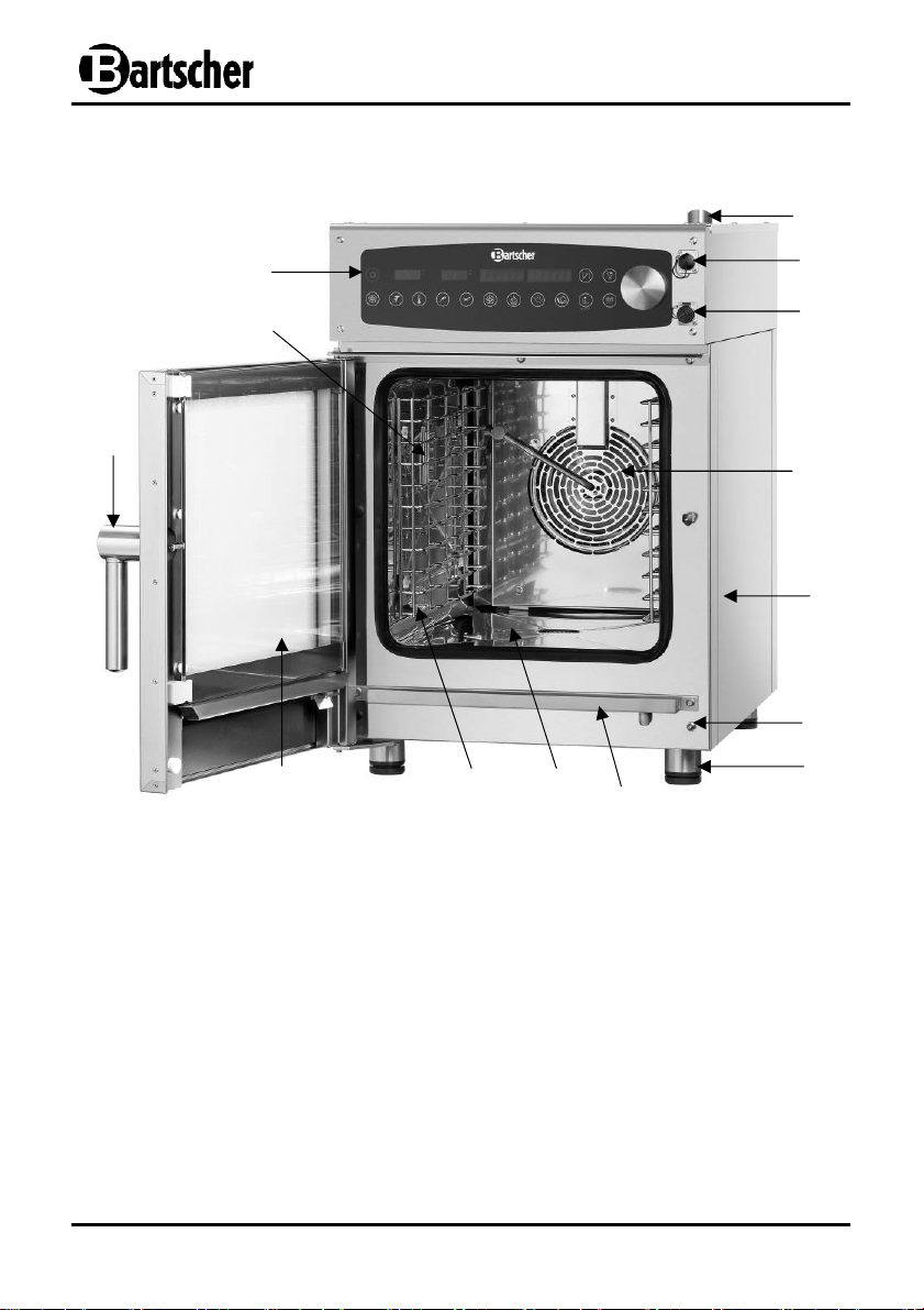
4. Technical data
4.1 Overview of parts
⑭
⑬
⑫
①
③
④
②
⑥
⑤
⑪
Steam outlet
①
USB connection
②
Temperature probe connection
③
Fan
④
Housing
⑤
Microswitch
⑥
Adjustable feet
⑦
- 46 -
⑦
⑨
⑩
⑧
Drain tray
Steamer chamber
Rails for shelves
Glass door
Glass door handle
Steamer chamber illumination
Control panel

4.2 Technical specification
Name
Combi steamer compact
Model:
Code-No.:
Capacity: up to 6 x 1/1 GN up to 10 x 1/1 GN
Temperature range: 50 °C – 280 °C
Power supply:
Rigid water
connection:
Water pressure: max. 3 bar
Dimensions:
Weight: 85.0 kg 95.0 kg
Equipment:
We reserve the right to make technical changes!
D6110 Digital D10110 Digital
117261 117201
6.9 kW / 400 V
50/60 Hz 3 NAC
3/4“
W 519 x D 803 x H 770 mm W 519 x D 803 x H 1,010 mm
1 spare fat filter for the electronic cooling fan,
1 grate 1/1 GN, 1 tray 1/1 GN, 1 water supply hose
13.8 kW / 400 V
50/60 Hz 3 NAC
Protective devices
The device is equipped with the following protective systems:
Door microswitch
The microswitch interrupts the device operation after opening the door: either the
heating system and the fan are turned off. After closing the door the interrupted
cycle is continued. It is forbidden to manually activate the microswitch when the door
is opened.
Motor overheating protection
The fan motor is equipped with the overheating protection which interrupts the
operation in case of overheating. The fan motor operation is restored automatically
when the temperature drops to the value in the safe range.
- 47 -

Steamer chamber protective thermostat
When the temperature in the steamer chamber reaches 350°C the thermostat opens
the supply circuit of the device heaters.
That protection must be reactivated by the technical service personnel as its
operation indicates that other elements must be inspected.
CAUTION!
That protection must be reactivated by the technical service personnel as its
operation indicates that other elements must be inspected.
Properties of the combi steamer compact Digital
• Model CNS
• Maximum capacity up to 6 x 1/1 or 10 GN 1/1
• Digital control can be configured with up to 99 programmes, up to 9 cooking phases
per program
• Compact longitudinal sliding GN
• Functions:
Air circulation/steaming/combined steaming/ delta T cooking / cooking in low
temperature / quick cooling / steamer compact devices with the automatic
cleaning system on demand
• Reversible motor operation (clockwise/counterclockwise) to optimize the cooking
climate
• Steam generation with use of direct injection
• 3 levels of fan speed control
• Adjustable steam outlet
• Steamer chamber illumination
• Double door glazing, easy opening of internal door for cleaning
• Removable rails for shelves
• Front connection for the optional core
• Front USB connection
- 48 -

Pressure limiter for the combi steamer compact
Core tem
perature sensor
Auxiliary equipment (not included in the delivery)
devices
• Made from chrome-plated brass, connection 3/4”
• Initial setpoint 3 bar, adjustment from 1 to 6 bar
• Maximum inlet pressure 16 bar
• Maximum operational temperature 65°C
• Weight: 0.4 kg
Code-No. 533051
Manual shower
• Hose length 2 m
• 1/2” cut-off valve for rigid water connection
• Handle for fixing on the combi steamer compact
Code-No. 116005
• Cable length: approx. 1.8 m
Code-No. 116000
The ideal supplement:
The matching holder, Code-No. 116008
Core temperature sensor set
Consisting of core temperature sensor and matching
holder to attach to the combi steamers
• Magnetic holder: W 130 x D35 x H 30 mm
• Weight: 0.57 kg
Code-No. 116009
- 49 -

5. Installation
5.1 General safety instructions
CAUTION!
All installation, connection and maintenance works for the device must be
performed by the qualified and authorized technician according to the valid
international, national and local regulations.
• Read through these instructions carefully before the installation and operation.
• Keep this operation manual. When the device is transferred to the third party, this
operation manual should be transferred as well.
• All operations connected with the installation, assembly, operation and maintenance
must be performed by the specialized personnel having required authorization
(from the producer or vendor). The required operations must be performed
according to the installation regulations for a given country and the safety
regulations.
• Do not use the accessories and spare parts not recommended by the producer.
They may be dangerous for the user and other people or may damage the device
and cause loss of warranty rights.
• Periodically inspect the electric supply cable for damages. Do not operate the device
with the damaged supply cable. When the cable is damaged it should be replaced
by the service company or qualified electrician in order to avoid the hazards.
• The defective installation, operation errors and maintenance and cleaning mistakes as
well as any modifications may cause the incorrect operation, damages and injuries.
• The producer is not responsible for the injuries or damages resulting from not
following the above regulations or tampering and using non-original spare parts.
• In case of failures or incorrect operation the device must be turned off. The required
repairs should be performed by the service company authorized by the producer
with use of original spare parts.
• Do not place other heat sources in the device vicinity, like deep fryers or cooking
plates.
• Do not store any flammable products in the device vicinity.
• In case of longer standstill disconnect the water and electric power supply.
- 50 -

• Any modification of the device must be authorized and performed by the authorized
professional technical personnel.
• It is forbidden to make any modifications in wiring of the device.
• In case not following the safety instructions above the device safety may become
limited.
The device fulfils the requirements of the low-voltage directive 2006/95/EC.
Moreover the device conforms to the following regulations regarding the electric
installations:
• EN 60335 general part;
• EN 60335-2-42;
The device fulfils the requirements of the electromagnetic compatibility directive
2004/108/EC.
5.2 Setup
• In the beginning make sure that there are no elements blocking the way to the
installation place through the doors, corridors or other communication routes.
• CAUTION: The device may overturn during transport, which may damage the device
itself, other objects or cause the injuries. Use the means appropriate for the device
weight. The device should not be dragged or tilted, but lifted perpendicularly to the
ground and handled in the horizontal direction.
• Before positioning the device check the dimensions and exact positions of the
electric, water, and extraction connections.
• The device must be positioned in a room with sufficient ventilation (not outdoors) in
order to avoid excessive concentration of harmful substances in the air.
• We recommend to position the device under the hood or to remove hot vapours and
odours from the device chamber outside.
• Remove the external package (wooden crate and/or carton box) and utilize it
according to the regulations valid in the country of installation.
• Check the device for damages and position it in the operation place.
• Never position the device in the vicinity of the flammable materials or containers with
such materials (walls, furniture, partition walls, gas cylinders) as it may cause the fire
hazard. When it is not possible, insulate such materials with use of non-flammable heat
insulation, following all fire protection regulations.
- 51 -

• The device must be positioned on the even surface to avoid its slipping or turning
over.
• The floor in the installation place must have load carrying capacity sufficient for
weight of the device, its base and weight with full load.
Fig. 1
The device is not designed for installation
in the furniture and it is required to keep the
minimum distance of 50 mm from the walls
and other devices (fig. 1).
Assure the possibility of full opening of the glass
door (180°).
Position the device in such way that its back side
is easily accessible for connecting the electric and
water supply and for maintenance.
Level the device. Use the level and appropriately
position the adjustable feet (fig. 2).
The height differences or tilting may negatively
influence the device operation.
Carefully remove the protective foil from the
external walls, avoiding leaving the glue
residuals.
Check if the ventilation holes and the vapours
outlet are not covered or blocked.
Fig. 2
- 52 -

5.3 Water connection
Fig. 3
The potable water connection must be positioned
in the vicinity of the device.
The water pressure must not be higher than 3 bar
(300 kPa). If the water pressure is higher, install
the pressure reducer before the device.
The water pressure should be in range
of 1.8 – 3 bar.
We recommend to install the water
softener/descaler in order to obtain the hardness
vale of 3 – 7° (German) (0.6 – 1.2 mmol/l).
For water hardness of 7° (German) and above
we recommend to connect the device with use
of appropriate water softener and the pressure
up to 3 bar.
The device is equipped with connection for the
delivered water supply hose. For the devices with
6 trays the connection is located in the bottom left
side (fig. 3), and for the devices with 10 trays – in
the bottom right side (fig. 4).
Before connection flush the system with sufficient
amount of water in order to remove any iron
particles.
Connect „Aqua“ connection to appropriate
installation of cold water supply with installed
cut-off valve and filter.
Make sure that the valve is installed in easily
accessible place.
Caution: In case of water supply hose damage
replace it with new one, do not reuse old hose.
Fig. 4
- 53 -

5.4 Drain connection
Fig. 5
Water flowing from the device drain may be hot
(90°C), therefore the drain hoses should be
resistant to such temperature.
The water drain is located in the bottom back
section of the device and is equipped with
connection pipe (Ø 40 mm).
Connect the pipe with the drain element (fig. 5,
pos. A).
The drain element is the water seal. However we
recommend to connect the drain pipe with open
funnel.
Check if the internal water seal is filled with water,
and if not, fill it through the drain in the device
chamber.
5.5 Electric connection
WARNING! Electric shock hazard!
The device can cause injuries due to improper installation!
Before installation and connecting the local power grid specification should be
compared with that of the device (see type label).
Connect the device only in case of compliance!
The electric installation must have appropriate earthing, conforming to the valid regulations.
The safety of the electric installation may be assured only when that installation fulfils the
requirements of the standards.
Before connecting the device make sure that the voltage and frequency values on the
rating plate are consistent with the existing electric installation. The allowable voltage
deviation is ±10%.
In order to connect the device directly to the power supply it is required to install the
interrupting switch between the device and the installation, suitable for the power. The
contacts of that switch must have the gap appropriate for the installation instructions,
assuring full disconnection in the overvoltage category III. The interrupting switch
should be installed in a place always accessible for the personnel.
- 54 -

Position the main switch, connected to the supply
cable, in „0“ (zero) position. Check if the cable
section is suitable for the power consumed by the
device.
The power supply values are specified in the table
below:
Fig. 6
117261/
D6110
117201/
D10110
400 V 3N 50/60 Hz
5 x 2.5 mm2
5 x 4 mm2
230 V 3 50/60 Hz
208 V 3 50/60 Hz
4 x 2,5 mm
2
4 x 12 AWG
4 x 6 mm
2
4 x 8 AWG
230 V 50/60 Hz
3 x 6 mm
//
230 V 2 50/60 Hz
208 V 2 50/60 Hz
2
//
//
//
//
The device must be connected to the potential levelling circuit of
efficiency conforming to the valid regulations.
The connection is the terminal fixed to the frame and marked with
Fig. 7
the symbol in fig. 7.
5.6 Start-up and commissioning
• Before the first start-up the device must be thoroughly inspected in order to confirm
the consistency of the device and its installation with the valid regulations, technical
data and recommendations for safety, included in this document.
Moreover take into consideration the following:
Temperature in the installation place must be higher than +4°C.
The device chamber must be empty.
- 55 -

All package elements must be completely removed, including the protective foil
on the external walls.
The venting holes must be permeable.
The parts disassembled during the installation must be reinstalled.
The main switch of the electric installation must be turned on and the gas and
water cut-off valves before the device must be opened.
Inspection during commissioning
• The commissioning of the device is realized upon the basis of the test cycle allowing
for checking the correctness of operation and may reveal any damages or problems.
• Start the device with use of main switch
T1
(fig. 8, page 62).
• Set baking cycle for 10 min. at temperature of 150°C and humidity 25%.
• Press key
T14
(fig. 8) „Start/Stop“.
• Perform thorough inspection according to the following:
The device chamber illumination is turned on after pressing key
It is turned off automatically after 45 seconds or after pressing key
T13
T13
(fig. 8).
again.
The device is turned off after opening the glass door and is turned on again after
closing it.
The thermostat for the temperature adjustment in the device chamber is
activated when the preset temperature is reached. The heater(s) is (are)
turned on periodically.
The fan motor(s) direction is changed automatically every 3 minutes
(that time depends on the cooking time).
In case of devices with two fans in the chamber the motors rotate in the same
direction.
• Check the water outlet direction from the moistening hose in the chamber in relation
to the fan.
• At the end of the cooking cycle the acoustic signal is emitted.
- 56 -

6. Operation manual
6.1 Safety tips for the user
CAUTION!
Carefully read the manual below as it includes the safety and operation
instructions.
Store the manual to use it at any moment.
The defective installation, operation errors and maintenance and cleaning
mistakes as well as any modifications may cause the incorrect operation,
damages and injuries.
CAUTION!
The device is designed for professional use and must be operated by the
professional personnel.
• All persons using the device must follow the recommendations and instructions in
this manual.
• The device must be operated by the trained personnel only. In order to limit the risk of
accidents or damages it is important that the personnel is periodically and precisely
instructed in range of safety.
• The device is not to be used by persons (also children) with reduced physical, sensory
or mental capabilities, or lack of experience and knowledge, unless they have been
given supervision or instruction.
• Children should be supervised to ensure that they do not play with the device.
• Never leave the flammable materials in the vicinity of the device. Fire hazard!
• During cooking or after it the containers for food and other objects may be very hot;
maintain caution during handling to avoid burns. They must be touched only in the
protective gloves. Burn hazard!
• Maintain special caution during opening the door of the device, during work and after
it. Burn hazard during emission of hot vapours from the device.
• Pay attention to the hot areas of the device surface which temperature may exceed
60°C.
- 57 -

T1 D1 D2 D3 D4
T13
M T11
T2 T4 T5
T6 T7
T8 T9 T3 T10 T12 T14
• Do not place any flammable objects or food articles with alcohol in the device: the
self-ignition and fire may occur, which may lead to explosions.
• Avoid salting of food in the device chamber. Whet it is necessary, clean the device
as quickly as possible: the device chamber may become damaged.
• Open the device door carefully when the chamber is hot. Burn hazard!
• In case of damages of the glass door elements immediately turn the device off and
contact the service company. Do not use the device before the door replacement.
• In case of standstill (e.g. 12 hours) leave the glass door slightly opened.
• In case of longer standstill (e.g. a few days) disconnect the water and electric power
supply.
6.2 Operation elements
Key Name
T1
ON/OFF
T2
Selection of operation mode
T3
∆T (cooking delta T)
T4
Temperature
T5
Core
- 58 -
Fig. 8
Function
Device turning on and off
Setting of air circulation / steam moistening /
combined steam moistening
Cooking in ∆T mode
Cooking in constant temperature
Temperature setting for the core (option)

T6
Time
T7
Fan Setting of fan speed 1 – 3
T8
Moistening
T9
Cooking phases / pre-heating
T10
Programs Selection of saved cooking programs
T11
Steam outlet Opening / closing of steam outlet
T12
ESC key Return key
T13
Steamer chamber illumination Turning on/off the device chamber illumination
T14
Start / Stop Activation / deactivation of cooking
D1
Temperature indicator
D2
Time / core indicator Indicator of cooking time or core temperature
D3
Fan speed / humidity indicator Indicator of fan speed and preset humidity
Cooking phase / program
D4
indicator
Setting of cooking time or selection of no
limitation mode
Setting of moistening in COMBI and STEAM
MOISTENING modes
Programming / activation and deactivation of
cooking phases and setting of pre-heating
Indicator of temperature in the cooking
chamber or ∆T
Indicator of program number or cooking phase
Knob rotation allows for setting of required
M
Knob / CODER
value. Knob pressing confirms the entered
value.
- 59 -

T1 D1 D2 D3 D4
T13
M
T11
T2 T4 T5
T6 T7
T8 T9 T3 T10 T12 T14
6.3 Introduction to the device operation
The device has been designed for preparation of the food products in closed rooms and
must be used for that purpose only. Any other use is considered incorrect and
dangerous and is forbidden.
The device must be supervised during the operation.
We recommend to pre-heat the device before cooking with use of automatic pre-heating
function (section 6.4.8, page 68).
The display is equipped with the touch sensors. In order to select a given function it is
required to press the corresponding key. In order to set the selected cooking parameter it
is required to press the flashing key.
Caution: using of thick gloves may make precise pressing of keys difficult.
Rotation of knob M (fig. 9) allows for setting the value of selected function (e.g. increase
or decrease temperature/time/humidity).
The entered value is confirmed by pressing knob M (fig. 9) or appropriate key.
Hint: pressing knob M (fig. 9) allows for deactivation of an alarm.
Device turning on and off
Pressing and holding key T1 (fig. 9) for 3 seconds turns the device on or off. After
turning on the device is in the standby mode and waits for setting of the cooking
parameters.
After turning the device off by longer pressing the main switch T1 (fig. 9) the cut-off valve
before the device is closed.
After turning the device off the electronic assembly ventilation above the chamber may
still operate in order to assure its cooling.
Fig. 9
- 60 -

Activation / deactivation of cooking
Pressing of key
T14
(fig. 9) allows for starting or stopping of the cooking process. Door
opening interrupts the cooking process. After closing the door the already started
cooking process is continued from the interruption point. The ongoing cooking cycle
may be interrupted with use of key
Cooling of device chamber
Press and hold key Esc
key
T14
“Start/Stop” (fig. 9) to start cooling. Only then it is allowed to close the door.
T12
(fig. 9) until the initial settings are restored. Then press
Cooling of the device chamber operates only when the temperature measured in the
chamber exceeds 50°C.
Steamer chamber illumination
In order to turn the illumination on press key
automatically after the defined time or after pressing key
T14
(fig. 9).
T13
(fig. 9). The illumination turns off
T13
(fig. 9) again.
- 61 -

D1 D2
inF 230 50 HU
MANUELL
T6 T4
T1
6.4 Manual programming
6.4.1 Setting of cooking temperature
Turn the device on by pressing key T1 (fig. 10), after turning on the device is in the
standby mode and waits for setting of the cooking parameters.
Press key
to increase the value or counterclockwise to decrease it. Press knob M or key T4
(fig. 10) to confirm the value. The set temperature is displayed on the indicator D1
(fig. 10). The cooking temperature depends on selected operation mode (section
6.4.4, page 63) and is:
Steam: min. 50°C - max. 120°C
6.4.2 Setting of cooking time
Use key T6 (fig. 10) to set the required cooking time, or select “no limitation“ mode.
After turning the device on the indicator D2 (fig. 10) normally shows setting “inF” (“no
limitation“).
The value may be changed by pressing key T6 (fig. 10). Then turn knob M clockwise to
increase the value or counter clockwise to decrease it.
The setting “no limitation“ is set by rotating knob M counter clockwise until the
indicator D2 (fig. 10) displays “inF”.
Press knob M (fig. 10) or key T6 (fig. 10) to confirm the value.
T14
(fig. 10) to set the cooking temperature. Then turn knob M clockwise
Air circulation: min. 50°C - max. 280°C
Combi: min. 50°C - max. 250°C
Fig. 10
- 62 -

T1 D
3
00:50
50
FAN 3
T7
MANUELL
6.4.3 Temperature setting and automatic pre-heating
The fan speed may be set to one of three available speeds:
SPEED 1 (low)
SPEED 2 (medium)
SPEED 3 (high)
Press key T7 (fig. 11) to set the fan speed.
Then turn knob M clockwise to increase the value or counterclockwise to decrease it.
Press knob M (fig. 11) or key T7 (fig. 11) to confirm the value. The set fan speed is
displayed on the indicator D3 (fig. 11).
6.4.4 Selection of operation mode
The device allows for selection of one of three available operation modes:
HOT AIR
COMBI
STEAM
In HOT AIR mode the food is prepared only with use of hot air and no moisture in form of
steam is introduced into the chamber (reduction of product humidity).
In STEAM mode air is enriched with steam (humidity 100%).
In COMBI mode either hot air and steam are used in adjustable ratio (set by the user).
Fig. 11
- 63 -

D
3
00:50
50
70 HU
MANUELL
T8
After turning on the device is normally in HOT AIR mode.
T8
Press key
(fig. 12) to switch into that mode.
Indicator D3 (fig. 12) shows humidity 0= 0 HU. Rotate knob M (fig. 12) to set the
required value. Press knob M (fig. 12) or key T8 (fig. 12) to confirm the operation
mode.
STEAM mode may be selected with use of key T8 (fig. 12). Indicator D3 (fig. 12) shows
value 100= 100 HU. Rotate knob M (fig. 12) to set the required value and confirm it
by pressing knob M (fig. 12) or key T8 (rys. 12).
COMBI mode may be selected with use of key T8 (fig. 12). Indicator D3 (fig. 12) shows
humidity between 10 and 90= 10 HU / 90 HU. Press key T8 (fig. 12) and rotate knob M
(fig. 12) to set the required value. Press knob M (fig. 12) or key T8 (fig. 12) to confirm the
value.
According to the description above the operation mode may change depending on preset
humidity:
Humidity = 0 HOT AIR Food preparation with use of hot air.
Humidity = 10-90 COMBI
Food preparation with use of hot air
and in presence of steam.
Humidity = 100 STEAM Food preparation in presence of steam
Fig. 12
- 64 -

D
1 D
2
20 C 200 0 HU
MANUELL
T5
6.4.5 Cooking with use of core (option)
An alternative for the cooking time / program phase is monitoring of the preparation
process with use of temperature measurement inside the product. That operation mode
is especially suitable for meat, poultry, and fish.
Press key T5 (fig. 13), indicator D2 (fig. 13) displays the preset temperature. Rotate knob
M
(fig. 13) clockwise to increase the temperature or counterclockwise to decrease it.
Press knob M (fig. 13) or key T5 (fig. 13) to confirm the value.
Hint: food preparation temperature must be always 5°C higher than the preset
temperature inside the product.
Core position (option):
The core should be placed in the prepared product in such way that its tip is positioned
in the central part of the highest volume.
Approximate temperature values inside the product:
FOOD TYPE
PREPARATION
METHOD
TEMPERATURE
Beef rare 50 °C
medium 60 °C
well 70 °C
Drumsticks well 80 °C
Chicken breast well 73 °C
White meat well 70-75 °C
General cooking well 85-90 °C
Fish boiled 67-72 °C
Fig. 13
- 65 -

TIME
TEMPERATURE
D
1 D
2
00:50
50
0 HU
T5
T3
MANUELL
6.4.6 Food preparation with use of delta T function
In opposition to the constant temperature, food preparation with use of delta T function is
realized according to the temperature rise in the device chamber in parallel to the
temperature rise inside the product, measured with use of core, always accordingly to the
preset value of delta T. Delta T corresponds to the temperature difference between the
product interior and the device chamber, which is maintained by the device until the end of
cooking (fig. 14). Food preparation with use of delta T function requires the core.
After pressing key T3 (fig. 15) the indicator D1 (fig. 15) shows ∆
T (
delta T)
.
Rotate knob M clockwise to increase the
Chamber temperature
value or counter clockwise to decrease it.
Press knob M or key T5 (fig. 15) to
confirm the value. Then set the
temperature in the product according to
Product temperature
the previous section.
Use of ∆T cooking mode:
Fig. 14
∆T mode is especially suitable for preparation of roast meat or ham of medium and
large size. That preparation method uses temperature in the device chamber lower than
in traditional preparation. The longer preparation time makes the product more crispy
and allows to avoid big weight losses.
The following ∆T are recommended:
• 30°C for red meat of temperature in the product b etween 45°C and 55°C;
• 25°C for red meat of temperature in the product b etween 75°C and 85°C.
Fig. 15
- 66 -

D
1 D
2
50 C 268 30 HU
STEP 3
T9 T2
6.4.7 Programming of the multiple-phase
cooking
Each cooking program may consists of multiple phases, for which various settings are
defined (preparation method, temperature, time, etc.). Each cooking program may
include up to 9 phases.
After entering the parameters for the first cooking phase as described above press key
T9
(fig. 16) and rotate knob M clockwise. Indicator D4 (fig. 16) displays the second
phase S T E P 2. Press key T2 (fig. 16) to confirm the intention of programming of the
next cooking phase.
Enter the parameters for the second cooking phase and repeat the steps described
above to add the successive cooking phases to the program.
Hint: adding of the successive cooking phase is possible only when the finish time or
the temperature inside the product are entered. If neither of those two parameters is set,
switching to the next phase during the food preparation is not possible.
Hint: during switching to the next cooking phase key T2 (fig. 16) flashes until pressing.
Flashing of that key indicates that the phase is not programmed and the device is
unable to realize it.
Programming examples:
Phase 1: STEAM 110°C 15 min. FAN 3 100 HU
Phase 2: STEAM 205°C 6 min. FAN 1 0 HU
Phase 3: COMBI 168°C 50°C FAN 1 30 HU
Fig. 16
- 67 -

D
4
00:50
50
0 HU
PRE? Y
T9 T14
6.4.8 Setting of the automatic pre-heating of the device chamber
In order to achieve good preparation effect we recommend pre-heating of the device
chamber with use of pre-heating function.
It may be realized automatically during the start of the cooking program.
After entering the parameters for the first cooking phase as described above press key
T9
(fig. 17) and rotate knob M (fig. 17) counterclockwise until the indicator D4 (fig. 17)
shows PRE? N. Press knob M (fig. 17) to activate the automatic pre-heating. The
indicator D4 (fig. 17) shows PRE? Y. Then rotate knob M (fig. 17) clockwise to return
to the selected cooking phase or start the new phase.
After starting with key
The automatic pre-heating heats the device to the temperature higher by 25°C than the
temperature set for phase 1 in order to assure better temperature after opening of the
glass door and placing the cold product in the chamber.
When the entered temperature is reached the acoustic signal is emitted. Then it is
allowed to place the food in the device chamber.
Caution: pre-heating must be realized with empty chamber. Before placing the
food inside wait for the acoustic signal.
T14
(fig. 17) the device starts pre-heating.
PRE? Y STEP 1 STEP 2 STEP 3 STEP 4 →
Fig. 17
- 68 -

00:50
50
0 HU
MANUELL
T9 T14
T11
6.4.9 Opening and closing of steam outlet
In HOT AIR mode there is a possibility of adjusting of the steam outlet opening and
closing. The steam outlet is designed for removing the moisture from the device
chamber.
Press key
T11
(fig. 18) to open the steam outlet.
Opening and closing of steam outlet is indicated by the state of key
ON = STEAM OUTLET OPENED
OFF = STEAM OUTLET CLOSED
Hint: the adjustment of steam outlet is possible only in HOT AIR mode. In COMBI
and STEAM modes the outlet is controlled automatically by the device.
T11
(fig. 18):
Fig. 18
- 69 -

D
4
00:50
50
0 HU
PRG 15
T9 T14
T10
6.5 Navigation in the recipes menu
6.5.1 Saving the cooking program in the device memory
Each cooking program defined in the manual mode and consisting of one or more
phases may be saved in the internal memory of the device for easy opening with use of
start menu and using in the future.
After entering all required cooking parameters press key
The indicator D4 (fig. 19) displays the number of the first free program in the memory
(for example, if there are 3 saved programs with numbers 1, 2 and 3, number 4 will be
displayed as the next free place in the memory).
Rotate knob M (fig. 19) to select the program number.
Then save the selected position by pressing key
The indicator D4 (fig. 19) shows MEM.
6.5.2 Loading the cooking program from the memory
In the standby mode press key T10 (fig. 19) and rotate knob M (fig. 19) to select the
number program, which is to be loaded, on indicator D4 (fig. 19).
Then start the cooking process by pressing key “Start/Stop”
Hint: the cooking phases for a given program may be previewed by pressing key T9
(fig. 19) and rotating knob M (fig. 19).
The indicator D4 (fig. 19) shows the current cooking phase (STEP).
T10
T10
(fig. 19) for 3 seconds.
(fig. 19) for 3 seconds.
T14
(fig. 19).
Fig. 19
- 70 -

D
4
00:50
50
0 HU DEL? Y
T9 T14 T10
6.5.3 Modification of the cooking program save in the memory
After selecting the cooking program its parameters may be changed according to
section “Manual programming”.
To save the changes press key
T10
(fig. 20) for 3 seconds. The modified program
overwrites the previous version.
6.5.4 Removing the program or its part from the memory
The program saved in the memory may be removed as a whole or partially.
Removing the whole cooking program:
1. Select the program to be removed
2. Select its first cooking phase (STEP 1)
3. Press and hold key
4. The indicator
5. Rotate knob
Confirm the operation by pressing knob M.
In order to remove a part of the cooking program select the cooking phase
to be removed and press key T9 (fig. 20). Then follow the instructions in
sections 4 and 5 above.
Hint 1: removing of one cooking phase removes also all successive
Example: if a program consists of 5 phases, removing of phase 3 removes also
Hint 2: after removing only a part of the program its remains are saved
T9
(fig. 20)
D4
(fig. 20) shows DEL? N
M
(fig. 20), the indicator D4 (fig. 20) displays the question DEL? Y.
phases.
phases 4 and 5.
in the memory as the last record (i.e. without the removed
phases).
Fig. 20
- 71 -

D
4
D
3
D
1 D
2
T9 T10
6.5.5 Importing and exporting the recipes from the USB memory
The device allows for importing and exporting the
cooking programs from the USB memory to the device.
Importing of cooking programs:
1. Turn the device on.
2. Connect the compatible USB memory to the USB
port (fig. 21).
Fig. 21
3. Press knob
M
(fig. 22) and key
T10
(fig. 22)
simultaneously.
4. The importing operation is finished when the display indicators show the following
information:
D1 D2 D3
uSb TFINISH E UPLOAD
5. Now it is allowed to remove the USB memory.
D4
Exporting of cooking programs:
1. Turn the device on.
2. Connect the compatible USB memory to the USB port.
3. Press knob M (fig. 22) and key T9 (fig. 22) simultaneously.
4. The exporting operation is finished when the display indicators show the following
information:
D1 D2 D3
D4
uSb TFINISH EDOWNLOAD
5. Now it is allowed to remove the USB memory.
Fig. 22
- 72 -

7. Cleaning and maintenance
7.1 Safety advice
CAUTION!
Before any activities connected with cleaning it is required to disconnect the
power supply, close the water supply and wait for complete cooling of the device.
o In order to assure reliable operation, hygiene and efficiency the device should be
cleaned everyday after work.
o Do not use any acid products, abrasive agents, caustic cleaning agents containing
sand or soda lye.
o Do not use steel wool, wire brushes or steel spatulas.
o In order to protect yourself from the eletric shock never immerse the device, supply
cable or plug in water or other fluids.
CAUTION!
The device is not designed for flushing with direct water jet. Therefore do not use
the pressurized jet for cleaning the device (inside and outside).
7.2 Cleaning
Regular cleaning of the device chamber
o The shelves rails may be removed from the device for easier cleaning. To do this,
unscrew the fixing bolts and remove the rails.
o Clean the device chamber only with lukewarm water and gentle cleaning agent.
All washed surfaced should be rinsed with clean water and thoroughly dried.
Pay attention to not to leave any washing agent residuals.
External cleaning
o Clean the external surfaces of the device only with cloth soaked in water.
o Use only agents designed for cleaning of high-grade stainless steel, as improper
cleaning agents may cause corrosion of the device.
o Do not use the agents containing chlorine (bleachers, hydrochloric acid, etc.).
o After cleaning dry and polish the surface with dry cloth.
- 73 -

To maintain correct temperature of the electronic
ld be cleaned
Cleaning of the device door
o Before cleaning of the door the device must
be completely cooled down.
o Double glazing facilitates cleaning. The internal
glass may be opened.
o To do this, loosen the upper and lower steel plate
locking the internal glass. Rotate the plates
clockwise.
o Tilt the internal glass (fig. 23).
o Clean the internal glass on both sides and the
device door with use of appropriate agents.
o Do not use any aggresive and abrasive cleaning
agents.
o Close the internal glass and put the steel plates in
Fig. 23
the initial position.
CAUTION!
Before closing of the device make sure that the internal glass is fixed with the
steel plates, otherwise it will not be possible to close the door.
7.3 Fan cleaning
Fig. 24
CAUTION!
In case of „Hi Temp“alarm the most probable reason is excessive contamination
of the fan. Clean the fan immediately!
- 74 -
elements of the device the fan shou
periodically, at least once a month.
The fan is located in the back part of the device
(fig. 24). Cleaning procedure:
1. Grab the fan tongue and pull it up from
the slot.
2. Remove the fan from the housing, clean
with lukewarm water and neutral cleaning
agent and dry with clean cloth.
3. Put the fan back into the housing and
slide into the slot.

8. Possible Malfunctions
Failure
The device cannot be
turned on
When it is still not possible to start the device after above activities, contact the
service company.
The fan stops during
the operation
When the failure persists contact the service company.
The chamber
illumination does not
work
When the failure persists contact the service company.
• Check if there is electric voltage and the main switch is
turned on.
• Check the fuses in the device.
• Make sure that the glass door is properly closed.
• Check if the parameters of selected cooking cycle are
correct.
• Make sure that there are no error messages.
Possible solutions
• Turn the device off and wait until the overheating protection
starts the motor automatically.
• Make sure that the ventilation holes are permeable.
Use only temperature-resistant light bulbs!
The internal illumination bulb replacement procedure:
- make sure that the switch before the device is
turned off,
- loosen the bolts and remove the shelves rails
from the left internal wall of the device,
- unscrew the illumination cover bolts,
- remove the cover, glass and seal,
- replace the damaged bulb with new halogen bulb 25 W,
- replace the cover, glass and seal,
-
reinstall the shelves rails.
The water is not
supplied through the
moistening pipes
When the failure persists contact the service company.
• Check if the water valve is opened.
- 75 -

CAUTION!
The above problems only serve for orientation and as examples. Should these or
similar problems occur, turn the device off immediately and discontinue using it. If
the failure cannot be removed, immediately contact the service company or vendor
in order to inspect and repair the device. Prepare the article number and the device
serial number specified on the rating plate on the back. Never attempt to repair the
device by yourself.
9. Waste disposal
Discarding old devices
At the end of its service life the discarded device has to be disposed in accordance with
the national regulations. It is advisable to contact a company which is specialized in
waste disposal, or just contact the local disposal service in your community.
WARNING!
To exclude any abuse and the dangers involved make the waste device unfit for
use before disposal. For that purpose disconnect device from mains supply and
remove mains connection cable from the device.
NOTE!
For the disposal of the device please consider and act
according to the national and local rules and
regulations.
Bartscher GmbH
Franz-Kleine-Str. 28
D-33154 Salzkotten phone: +49 (0) 5258 971-0
Germany fax: +49 (0) 5258 971-120
- 76 -
 Loading...