

TankScan™ W-Series
WC2 Controller
Installation Manual
Version 99L15xz
ID#11680
CUS
Introduction
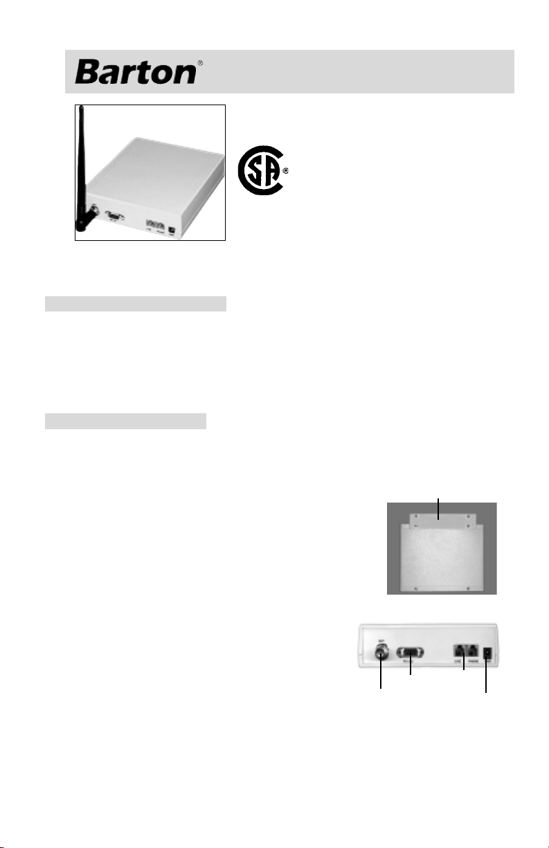
The TankScan Wireless Level System Controller includes a radio/modem
enclosure, an antenna, and an AC power adapter.
System Installation Steps
A. Install Controller (distance & line-of-sight location predetermined).
B. Install monitor(s) on the tank(s)
C. Install fill indicator(s) at a accessible location near the fill point.
D. Install software on host PC
E. Power up and configure the Controller
F. Power up the monitor(s) and fill unit(s).
Controller Installation
PRELIMINARY
NOTICE
Do not install Controller near any RF sources (TV, Radio, etc.). Interference
from such devices can cause data loss and Controller malfunctions.
1. Place Controller on stable flat surface or mount on
wall.
a. If desired, install the self-adhesive rubber feet.
b. To wall mount, attach mounting plate to bottom of
enclosure using supplied screws, then attach the
assembly to the wall with the antenna connector
facing up.
Note: Controller must be within reach of the power source/outlet,
phone jack (if used) and PC (if direct
connection is used).
2. Attach Antenna to Controller (pointed upward).
Note: Ant. connector has left-handed thread.
3. Connect Phone Line, using supplied RJ11 cable.
Plug one end into the Controller and the other
into the wall phone jack. If a phone is needed, plug it into the second RJ11
socket on the Controller. Note: RJ11 sockets are in parallel, either can be
used for line.
Mounting Bracket
See Dimensions
on Page 4.
RS232
Antenna
CAUTION
To reduce the risk of fire, use only No. 28 AWG or larger telecommunications line cord.
4/2001
Phone
Line
Power
1
Controller Installation (continued)
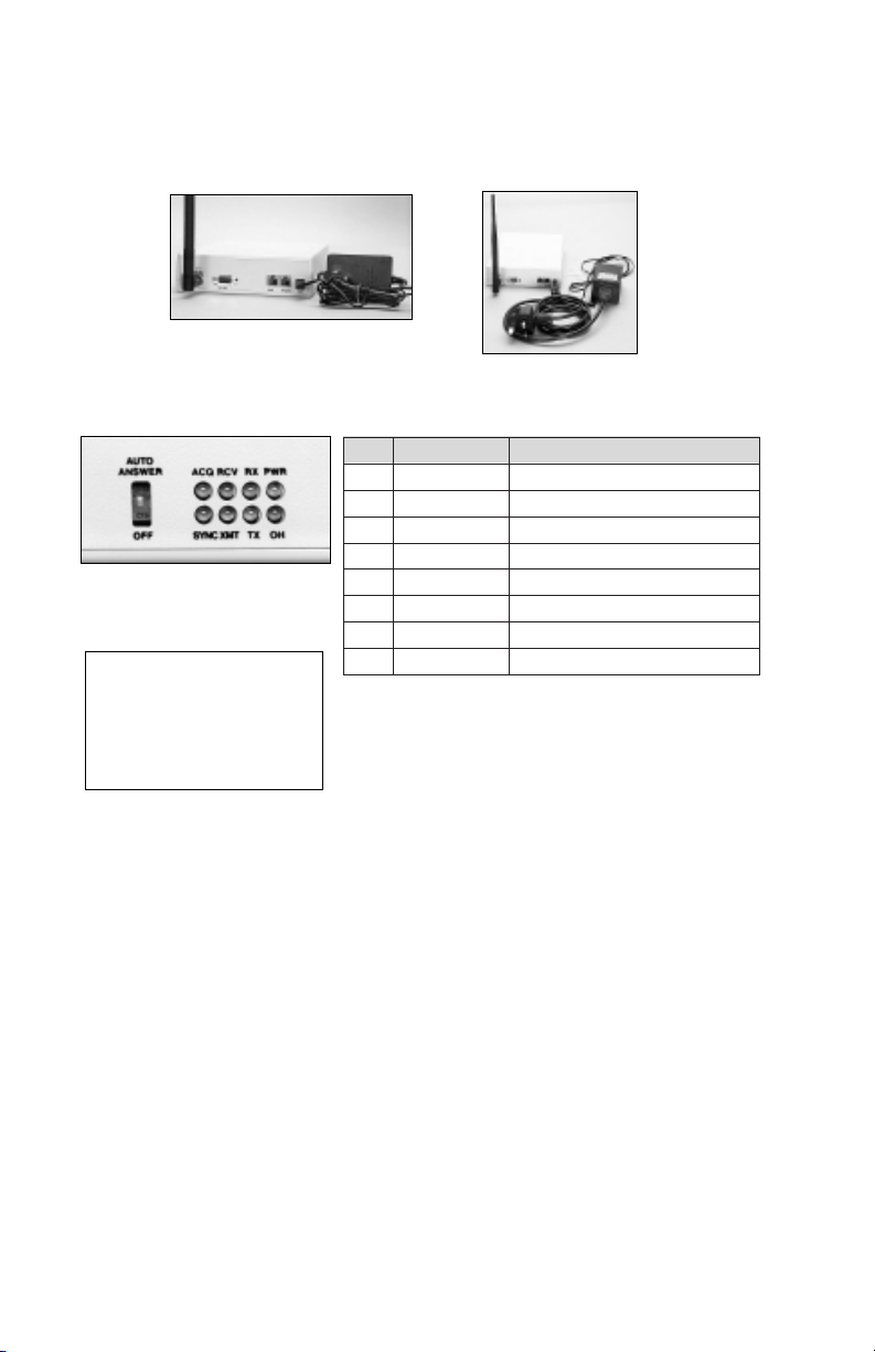
4. Plug in the appropriate Power Adapter (US or EU type included, per
order). Plug the barrel-ended connector into Controller and the 3-prong
plug into an unswitched AC outlet.
(US) Power Adapter
(EU) Power Adapter
5. Check front panel indicator lights to make sure unit is operating.
lebaLemaNnoitpircseD
RWPrewoPnositinU
HOkooHffOkoohffoenilenohP
XTataDtimsnarTatadgnidnesmedoM
XRataDevieceRatadgniviecermedoM
Front Panel Indicator Lights
& Auto Answer Switch
The AUTO ANSWER switch
sets the modem's answer
mode. If OFF, the modem will
not answer incoming calls - it
will only call out on a pre-set
schedule or alarm.
TMXtimsnarToidaRatadgnittimsnartoidaR
VCRevieceRoidaRatadgnivieveroidaR
CNYScnySemiTdettimsnartgniebegassemcnySemiT
QCAedoMeriuqAoidaraivstinudleifgniriuqasirellortnoC
During normal operation (with no level requests,
fill operations, or modem activities), the power
light will be on and the "SYNC" light will flash
every 32 seconds.
6. Configure the Controller using the DataScan Plus PC software.
7. The Controller is now ready to receive signals from the level Monitor(s)
setup during the DataScan Plus PC software configuration process.
2
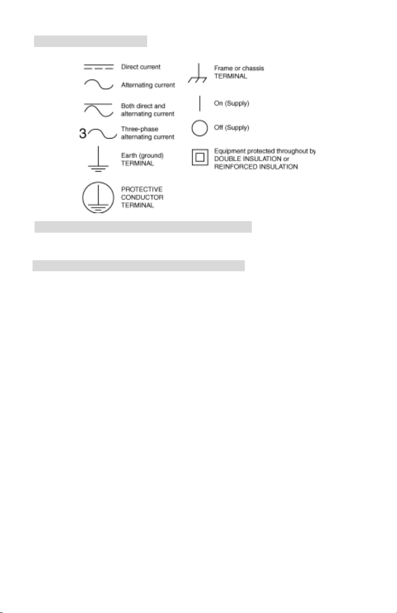
Symbol Information
The following symbols may be used in this manual or on the instrument:
Technical Support/Warranty Service/Repair
US: 626-961-2547 • Canada: 403-291-4814 • Europe: 441243826741
Specifications
Operating Temperature ........... +32°F to +140°F (0°C to +60°C)
Enclosure ............................... NEMA-1/IP30 - Indoor Use Only
Safety Ratings......................... UL1950, CSA950, and EN60950
Flame Class Rating .................. UL94V-0
Power Requirements ............... 110 VAC (60 Hz) US;
220 VAC (50-60 Hz) Europe, 5 VA
Internal Transceiver ................. (for use with up to 30 field devices)
Transmits up to 500 feet (150 m), line-of-sight,
in the unlicensed 902-928 MHz band (North
America) or 869.7-870 MHz band (Europe)
Phone Modem ........................ Internal (calls host per schedule or alarm and
accepts calls from host)
Line Impedance: 600 Ohm, transformer
coupled (CTR21 - complex impedance)
Dial Type: DTMF or Pulse (subject to national
approvals)
Baud Rate: 2400 (CCITT V.22bis); 1200
(CCITT V.22 or Bell 212A)
Note: This modem will not detect cadenced
dial tone, but will blind dial on command.
For compliance and approval statements, see
pages 5-7.
Data Storage .......................... Depends upon number of field devices and
frequency of readings.
Host Software ........................ Barton DataScan
®
Plus PC Software
Mounting ............................... Tabletop or wall mount
Shipping Weight (approx.) ....... Controller, (standard) Antenna, & AC adapter
1.7 lbs (0.8 kg)
3

Dimensions
Replacement Parts List
Part Description Part Number
AC Power Adapter (US) .......... TL10-2009T
Antenna (standard) .................. TL10-2004T
Optional Outdoor Antenna (with mount):
20-ft. cable ......................... WC20-2046B-1
30-ft. cable ......................... WC20-2046B-2
Telephone Cable (10').............. TL10-2007T
PC Cable ............................... TS10-1173T
4

COMPLIANCE STATEMENTS
FCC COMPLIANCE STATEMENTS FOR WC20
FCC PART 68 NOTICE
This equipment complies with FCC Part 68 rules. The FCC registration number and
Ringer Equivalent Number (REN) are printed on a label attached to the bottom of the
enclosure. You must, upon request, provide this information to your telephone company.
The REN number is used to determine the maximum number of devices that may be
connected to the phone line and still have all those devices ring when your number is
called. To determine the number of devices that may be connected to your line, as
determined by the REN, contact your local telephone company.
If your telephone equipment causes harm to the telephone network, the telephone
company may discontinue your service temporarily. If possible, they will notify you in
advance. If advanced notice is not practical, you will be notified as soon as possible. You
will be informed of your right to file a complaint with the FCC.
If there is a problem with the telephone network, the telephone company may ask you to
disconnect your equipment from the telephone line until the problem has been corrected
or until it is determined that your equipment is not malfunctioning.
Your telephone company may make changes in its facilities, equipment, operations, or
procedures that could affect the proper functioning of your equipment. If they do, you will
be notified in advance to give you an opportunity to maintain uninterrupted telephone
service.
This equipment cannot be used on coin service provided by the telephone company.
Connection to party lines is subject to state tariffs.
There are no user serviceable parts in this modem. If there is a problem or the modem
needs to be repaired or serviced, return it to the company where it was originally
purchased.
FCC applicable REN number is 0.6B.
FCC PART 15 NOTICE
This equipment has been tested and found to comply with the limits for Class B digital
device, pursuant to Part 15 of the FCC Rules. These limits are designed to provide
reasonable protection against harmful interference when the equipment is operated in a
residential installation.
This equipment generates, uses, and can radiate radio frequency energy and, if not
installed and used in accordance with the instruction manual, may cause harmful interference to radio communications. However, there is no guarantee that interference will not
occur in a particular installation. If this equipment does cause harmful interference to radio
or television reception, which can be determined by turning the equipment off and on, the
user is encouraged to try to correct the interference by one or more of the following
measures: re-orient or relocate the receiving antenna, increase the separation between the
equipment and receiver, connect the equipment into an outlet on a circuit different from
that to which the receiver is connected, and/or consult the dealer or an experienced
radio/TV technician for help.
The user is cautioned that changes and modifications made to this equipment without
approval of the manufacturer could void the user’s authority to operate this equipment.
Contains Transceiver Module, FCC ID: OKZ-WC20-2040B.
WARRANTY AND REPAIR SERVICE IN THE USA:
Barton Instrument Systems
900 South Turnbull Canyon Road
City of Industry, CA 91745
1-800-291-3550, ext. 269 or (626) 961-2547
5

CANADIAN COMPLIANCE STATEMENTS FOR WC20
The Industry Canada (IC) label identifies certified equipment. This certification means that
the equipment meets certain telecommunications network protective, operational, and
safety requirements. The department does not guarantee the equipment will operate to the
user’s satisfaction.
Operation is subject to the following two conditions: (1) this device may not cause
interference, and (2) this device must accept any interference, including interference that
may cause undesired operation of the device.
Before installing this equipment, make sure you are permitted to connect it to the facilities
of the local telecommunications company. You must install the equipment using an
acceptable method of connection. In some cases, you may also extend the company’s
inside wiring for single individual service by means of certified connector assembly
(telephone extension cord). You should be aware, however, that compliance with the
above conditions may not prevent degradation of service in some situations.
Repairs to certified equipment should be made by an authorized Canadian maintenance
facility designated by the supplier. Any repairs or alterations made by a user to this
equipment, or equipment malfunctions, may give the telephone communications company
cause to request the user to disconnect the equipment.
For your own protection, make sure that the electrical ground connections of the power
utility, telephone lines, and internal metallic water pipe system, if present, are connected
together. This precaution may be particularly important in rural areas.
(IC) applicable REN number is 0.6B.
CAUTION
Do not attempt to make electrical ground connections yourself, contact the appropriate
electrical inspection authority or an electrician.
NOTICE
The Ringer Equivalent Number (REN) assigned to each terminal device provides an
indication of the maximum number of terminals allowed to be connected to a telephone
interface. The termination on an interface may consist of any combination of devices,
subject only to the requirement that the sum of the REN numbers of all devices does not
exceed 5.
EMISSION REQUIREMENT
This Class B digital apparatus meets all requirements of the Canadian InterferenceCausing Equipment Regulation.
WARRANTY AND REPAIR SERVICE IN CANADA:
Barton Instrument Systems
3840 - 11A Street N.E.
Calgary, Alberta T2E 6M6
(403) 291-4814
Certification No.: CAN 33991032172A
CE COMPLIANCE STATEMENT FOR WC21
This product has been tested and confirmed to be in compliance with all EU EMC and
LVD Directives (in effect at the time of testing) for light industry use. There may be a
temporary degradation of performance at extreme levels of electro-magnetic interference.
This instrument complies with the Low Voltage Directive 73/23/EEC. For further details,
contact Barton Instrument Systems.
6
Approvals Pending

EU CTR21 STATEMENT FOR WC21
Network Connection
This apparatus is suitable for connection for direct 2 wire connection to the
PSTN and indirect 2 wire connection to the PSTN via compatible extensions
on a PABX system.
Facilities
The WC21 Controller's modem has been approved for use with the following
facilities:
• Signalling to the PSTN using DTMF signalling only
• Auto-answering
• Auto-call clearing
• Data modem
The modem should be set up for blind dialling (e.g., dial after delay, no dial tone
detection).
Any other usage will invalidate the approval of the apparatus if as a result it
then ceases to conform with the standards against which approval was gained.
Connection Methods
This apparatus is designed for connection to the PSTN using a modular jack
connection (RJ 11).
Connection to national networks in the EU may require an adapter compatible
with the national network.
CTR21 Type Approval
Annex II - Type Approval
The equipment has been approved in accordance with Council Decision 98/
482/EC for paneuropean single terminal connection to the Public Switched Telephone Network (PSTN). However, due to differences between the individual PSTNs
provided in different countries, the approval does not, of itself, give an unconditional assurance of successful operation on every PSTN network termination
point.
In the event of problems, you should contact your equipment supplier in the
first instance.
Annex III - Network Compatibility Declaration
We, Barton Instrument Systems of 900 South Turnbull Canyon Road, City of
Industry, CA91749, USA, declare under our sole responsibility that the WC20
Controller's internal modem is designed to interwork with the following networks:
Austria, Belgium, Denmark, Finland, France, Germany, Greece, Iceland, Ireland,
Italy, Liechtenstein, Luxembourg, Netherlands, Norway, Portugal, Spain, Sweden, Switzerland, United Kingdom.
and that there may be interworking problems with the following networks:
Germany, Greece, Portugal, Spain.
The network compatibility is not dependent on physical or software switch
settings.
If you wish to use this equipment on another network, please contact your
equipment supplier.
7

Order Code
seireS-WnacSknaT
rellortnoC_2CW
NOITARUGIFNOC
OIDAR
MEDOM
)noitpO(erutuF
)noitpO(RETAEH
ANNETNA
REWOP
2CW # - X#X#X
)zHM829-209(aciremAhtroN0
)zHM078-7.968(eporuE1
EDOCREDRO
lanretnI,naciremAhtroNA
)12RTC(lanretnI,naeporuEC
enoN0
enoNN
retaeH/wH
)rellortnoCnostnuoM(elgnAthgiR,lacoL1
tnuoMtekcarB,etomeR3
)gulPnaciremAhtroN(zH06/CAV011A
)gulPKU(CAV022B
)gulPnaeporuE(CAV022C
Barton Instrument Systems, LLC
900 S. Turnbull Canyon Rd.
City of Industry, CA 91745 USA
(626) 961-2547
On the Web at www.barton-instruments.com
©Copyright 2000, Barton Instrument Systems, LLC. All rights reserved.
8
 Loading...