

Page 1
BARTELL MORRISON INC.
artell
OWNER’S
MANUAL
WALK-BEHIND
Bartell Morrison Inc.
375 Annagem Blvd.,
Mississauga, ON, Canada
L5T 2A7
Toll Free (N.A.): 1 866 501 1683
Local: +1 905 364 4200
Fax: +1 905 364 4201
POWER TROWELS
B436
B430
B436
B436E
B436E
B436SD
B436SD
B446
B440
B446
ORIGINAL
LANGUAGE
Doc. # OI-B09001
Doc. # OI-B09001
Orig. Rel. - 05-2010
Orig. Rel. - 05-2010
Curr. Rev. - 00
Curr. Rev. - 02
Rev. Date - 05-2010
Rev. Date - 06-2013
Page 2

Bartell Morrison Inc. Bartell Morrison (USA) LLC
25
375 Annagem Blvd. 12 Industrial Drive,
Mississauga, Ontario, Canada Keyport, New Jersey, USA
L5T 3A7 07735
Toll Free (N.A.): (866) 501-1683 Toll Free: 888-999-1570
Phone: (905) 364-4200 Phone: (732) 566-5400
Facsimile: (905) 364-4201 Facsimile: (732) 566-5444
www.bartellmorrison.com www.bmiamerica.com
ORIGINAL LANGUAGE OPERATING INSTRUCTIONS FOR
BARTELL WALK-BEHIND POWER TROWELS
© 2010 Bartell Morrison Inc.
2013
No part of this work may be reproduced or transmitted in any
form or by any means, electronic or mechanical, including
photocopying and recording, or by any information storage or
retrieval system without the prior written permission of Bartell
Morrison Inc. unless such copying is permitted by federal
copyright laws.
Address inquiries or reference permissions care of:
Bartell Morrison Inc.,
375 Annagem Blvd.,
Mississauga, Ontario,
Canada, L5T 3A7
Revision
0 05/2010 Initial release RL
1
2
Date Description Approved by.
06/2013 Assembly instructions updated. AL
ALInstructions and company information update.08/2012
Page 3
WALK BEHIND POWER TROWEL INSTRUCTION MANUAL
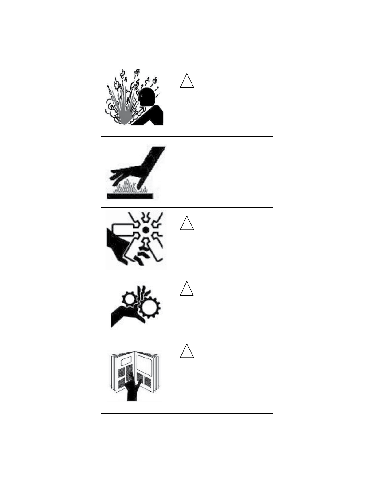
SAFETY PRECAUTIONS
DANGER
!
EXPLOSION HAZARD
Never operate the machine in an
explosive atmosphere, near
combustible materials or where
ventilation does not clear exhaust
fumes.
WARNING
BURN HAZARD
Never come into contact with the
engine or muffler when engine is
operating or shortly after it is
turned off. Serious burns may
occur.
CAUTION
!
ROTATING HAZARD
Never place hands or feet inside
safety guard rings. Serious injury
will result from contact with rotating
blades.
CAUTION
!
MOVING PARTS
Before starting the machine ensure
that all guards and safety devices
are in place and functioning
properly.
!
ATTENTION
READ OWNERS MANUAL
Read and understand operator's
manual before using this machine.
Failure to follow operating
instructions could result in serious
injury or death.
375 ANNAGEM BLVD., MISSISSAUGA, ONTARIO, CANADA, L5T 3A7, 905-364-4200 FAX 905-364-4201
375 ANNAGEM BLVD., MISSISSAUGA, ONTARIO, CANADA L5T 3A7, 905-364-4200 FAX 905-364-4201
25 INDUSTRIAL DRIVE, KEYPORT, NEW JERSEY, USA, 07735, 732-566-6400 FAX 732-566-5444
CREATED: 07/04
REVISED: 05/10
06/13
Page 4

WALK BEHIND POWER TROWEL INSTRUCTION MANUAL
6. BELT GUARD ........................................................................................................................................................9
WALK BEHIND POWER TROWEL INSTRUCTION MANUAL
TABLE OF CONTENTS
QUALITY ASSURANCE/MACHINE BREAK-IN .......................................................................................................4
WALK-BEHIND POWER TROWEL WARRANTY ....................................................................................................5
MAINTENANCE RECORD ........................................................................................................................................6
ROUTINE SERVICE INTERVALS ............................................................................................................................. 7
FOREWORD.............................................................................................................................................................. 9
SAFETY PRECAUTIONS ..........................................................................................................................................9
ASSEMBLY INSTRUCTIONS ...................................................................................................................................9
1. TROWELS ............................................................................................................................................................. 9
2. STABILIZER RING.................................................................................................................................................9
3. HANDLE ASSEMBLY ............................................................................................................................................9
4. STATIONARY RING ..............................................................................................................................................9
5. ENGINE CONTROLS ............................................................................................................................................ 9
6. BELT GUARD ........................................................................................................................................................9
DIAGRAM 1 ............................................................................................................................................................. 10
OPERATION (FLOATING) ......................................................................................................................................11
11
11
11
11
11
11
11
11
11
11
11
12
12
12
12
12
12
13
14
14
16
17
17
18
19
20
22
TABLE OF CONTENTS
QUALITY ASSURANCE/MACHINE BREAK-IN .......................................................................................................4
WALK-BEHIND POWER TROWEL WARRANTY ....................................................................................................5
MAINTENANCE RECORD ........................................................................................................................................6
ROUTINE SERVICE INTERVALS ............................................................................................................................. 7
FOREWORD.............................................................................................................................................................. 9
SAFETY PRECAUTIONS ..........................................................................................................................................9
ASSEMBLY INSTRUCTIONS ...................................................................................................................................9
1. TROWELS ............................................................................................................................................................. 9
2. STABILIZER RING.................................................................................................................................................9
3. HANDLE ASSEMBLY ............................................................................................................................................9
4. STATIONARY RING ..............................................................................................................................................9
5. ENGINE CONTROLS ............................................................................................................................................ 9
SETUP PROCEDURE
OPERATION (FINSHING) .......................................................................................................................................
1. STARTING PROCEDURES - WARM TEMPERATURES ...................................................................................
2. STARTING PROCEDURES - COLD TEMPERATURES .....................................................................................
3. STOPPING PROCEDURES ................................................................................................................................
LUBRICATION ........................................................................................................................................................
1. ENGINE OIL.........................................................................................................................................................
2. SPIDER PLATE ...................................................................................................................................................
375 ANNAGEM BLVD., MISSISSAUGA, ONTARIO, CANADA, L5T 3A7, 905-364-4200 FAX 905-364-4201
25 INDUSTRIAL DRIVE, KEYPORT, NEW JERSEY, USA, 07735, 732-566-6400 FAX 732-566-5444
3. GEARBOX ...........................................................................................................................................................
4. GEARBOX OIL CHANGE ....................................................................................................................................
5. GREASE FITTINGS.............................................................................................................................................
ENGINE OIL SPECIFICATIONS................................................................ ..............................................................
STORAGE................................................................................................................................................................
MAINTENANCE................................................................................................ .......................................................
1. AIR CLEANER .....................................................................................................................................................
2. LUBRICATION .....................................................................................................................................................
3. SPARK PLUG ......................................................................................................................................................
4. BELT TENSION ...................................................................................................................................................
ELECTRIC POWER TROWEL OPERATION................................ ..........................................................................
SETTING UP THE ELECTRIC POWER TROWEL .................................................................................................
STARTING THE ELECTRIC POWER TROWEL ....................................................................................................
ELECTRIC POWER TROWEL WIRING DIAGRAM ...............................................................................................
TROWEL ARM ADJUSTMENT FIXTURE ..............................................................................................................
1. ADJUSTMENT PROCEDURE .............................................................................................................................
TROUBLESHOOTING.............................................................................................................................................
SPECIFICATIONS ...................................................................................................................................................
COMPANY INFORMATION ....................................................................................................................................
NOTES................................ .....................................................................................................................................
10
13
13
13
13
13
13
13
13
13
13
13
13
14
14
14
14
14
14
15
16
16
18
19
19
20
21
22
23
CREATED: 07/04
REVISED: 06/13
Page 5

WALK BEHIND POWER TROWEL INSTRUCTION MANUAL
QUALITY ASSURANCE / MACHINE BREAK IN
The Bartell Walk-Behind Power Trowel is the product of extensive engineering
development designed to give long life and unmatched performance. The Walk-Behind
Power Trowels are shipped partially assemble, and only require filling with fuel and a brief
check of lubricant levels in preparation for operation.
You can help ensure that your P ower Trowel will perform at top levels by observing a
simple routing on first use. Consider that your new Power Trowel is like a new car. Just
as you would break in a new car to the road or any new machine to the job, you should
start gradually and build up to full use. Learn what your machine can do and how it will
respond. Refer to the engine manufacturer’s manual for run-in times. Full throttle and
control may be used after this time period, as allowed by material. This will serve to
further break in the machine on your specific application, as well as provide you with
additional practice using the machine.
We thank you for the confidence you have placed in us by purchasing a Bartell WalkBehind Power Trowel and wish you many years of satisfied use.
375 ANNAGEM BLVD., MISSISSAUGA, ONTARIO, CANADA, L5T 3A7, 905-364-4200 FAX 905-364-4201
375 ANNAGEM BLVD., MISSISSAUGA, ONTARIO, CANADA L5T 3A7, 905-364-4200 FAX 905-364-4201
25 INDUSTRIAL DRIVE, KEYPORT, NEW JERSEY, USA, 07735, 732-566-6400 FAX 732-566-5444
artell
CREATED: 07/04
4
REVISED: 05/10
06/13
Page 6

WALK BEHIND POWER TROWEL INSTRUCTION MANUAL
WALK-BEHIND POWER TROWEL WARRANTY
All products sold by Bartell Morrison Inc. and Bartell Morrison (USA) LLC (the “Company”) are warranted
against defects in materials and/or workmanship; excluding normal wear on wearing components and
components covered by a separate original manufacturers warranty, for a period of 24 months from the
date of sale to the original end user purchaser provided that certain conditions have been met.
Conditions:
1. The equipment serial number has been registered with the Company or its approved dealers,
distributors, representatives or agents.
2. The equipment has been operated in an appropriate manner by qualified individuals.
3. The equipment has been properly maintained as per the instructions included in the Owner’s
Manual.
4. All claims for warranty must be filed on proper forms and include the serial number of the
equipment along with proof of purchase.
Any evidence of failure to meet these conditions may result in a denial of the warranty claim.
Consideration of warranty claims will be at the sole discretion of the Company, or its authorized dealers,
distributors, representatives or agents.
The Company may, at its discretion, request that the equipment to be considered for warranty be returned
at the owner’s expense to an authorized repair facility for inspection.
Under this warranty we may, at our discretion
, repair or replace a part or the whole of the defective
component or equipment.
Our Warranty coverage is limited to the cost to repair or replace the defective portion of the equipment and
a reasonable (as determined by the Company) amount of labour to conduct the repair or replacement.
Under no circumstances shall the Company be liable for any additional or exceptional costs beyond the
cost to repair or replace the defective portion of the equipment. The Company shall not be held
accountable for; costs associated with travel to inspect or repair defective equipment, costs for transporting
defective equipment to or from an authorized repair facility, costs incurred to repair or replace the defective
equipment at any facility other than one authorized by the Company or ancillary damage caused by or as a
result of the defective equipment.
Under no circumstances shall equipment be returned to the Company or its authorized dealers, distributors,
representatives or agents without the approval of the Company as evidenced by a Returned Goods
Number. To obtain a Returned Goods Number contact the factory or your authorized dealer, distributor,
representative or agent.
This warranty is for the sole benefit of
the original end user purchaser and is not transferable to any other
company or person.
36
375 ANNAGEM BLVD., MISSISSAUGA, ONTARIO, CANADA, L5T 3A7, 905-364-4200 FAX 905-364-4201
375 ANNAGEM BLVD., MISSISSAUGA, ONTARIO, CANADA L5T 3A7, 905-364-4200 FAX 905-364-4201
25 INDUSTRIAL DRIVE, KEYPORT, NEW JERSEY, USA, 07735, 732-566-6400 FAX 732-566-5444
CREATED: 07/04
5
REVISED: 05/10
06/13
Page 7

WALK BEHIND POWER TROWEL INSTRUCTION MANUAL
MAINTENANCE RECORD
PREVENTATIVE MAINTENANCE AND ROUTINE SERVICE PLAN
This Walk-Behind Power Trowel has been assembled with care and will provide years of service. Preventative
maintenance and routine service are essential to the long life of your Power Trowel. Your dealer is interested in
your new machine and has the desire to help you get the most value from it. After reading through this manual
thoroughly, you will find that you can do some of the regular maintenance yourself. However, when in need of parts
or major service, be sure to see your Bartell dealer. For your convenience we have provided this space to record
relevant data about your Walk-Behind Power Trowel. When in need of parts or service be prepared to provide your
Trowel serial number. Locate the serial number now and record in the space below.
Date Purchased:
Dealer Name:
Dealer Phone:
REPLACEMENT PARTS USED MAINTENANCE LOG
PART NO. QUANTITY COST DATE DATE OPERATION
Type of Machine:
Model:
Serial Number:
375 ANNAGEM BLVD., MISSISSAUGA, ONTARIO, CANADA, L5T 3A7, 905-364-4200 FAX 905-364-4201
375 ANNAGEM BLVD., MISSISSAUGA, ONTARIO, CANADA L5T 3A7, 905-364-4200 FAX 905-364-4201
25 INDUSTRIAL DRIVE, KEYPORT, NEW JERSEY, USA, 07735, 732-566-6400 FAX 732-566-5444
CREATED: 07/04
6
REVISED: 05/10
06/13
Page 8
WALK BEHIND POWER TROWEL INSTRUCTION MANUAL
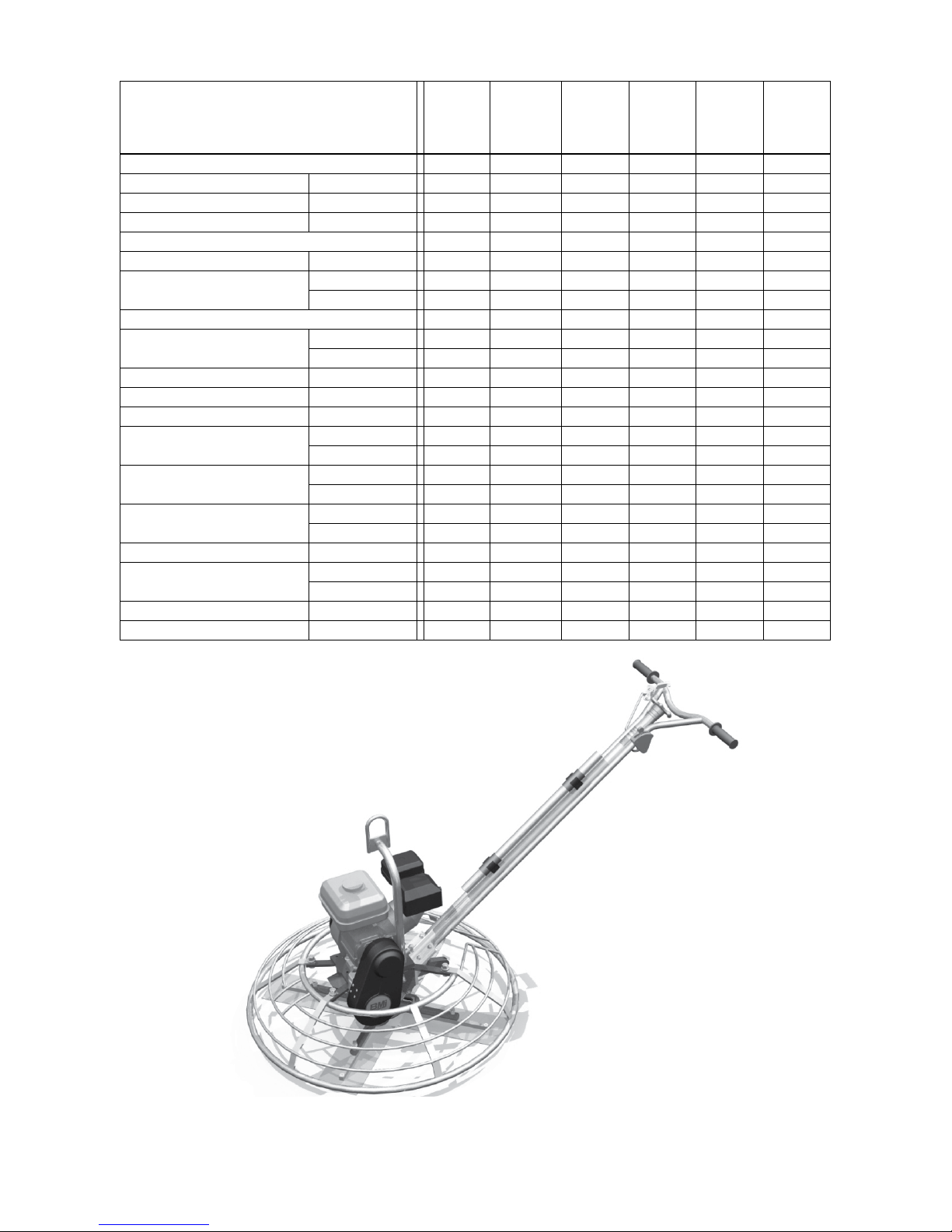
Routine Service
Intervals
General Inspection:
Guards Check
Warning stickers Check
Test run: Check operation
Controls:
Dead-man switch operation Check
Pitch control
Engine:
Engine oil
Engine oil filter Replace
Oil cooler Clean
Cooling Fins Clean
Air cleaner
Air Intake Line
Drive Belt
Valve clearance Check-adjust
Fuel filter
Fuel Tank Clean
Engine wiring Check
Check
Lubricate
Check Level
Change
Check - clean
Replace
Check
Replace
Check tightness
Replace
Check & Clean
Replace
Each
use
After 1.5
months
or
50 hrs
Each 3
months
or
100 hrs
Each 6
months
or
200 hrs
Each 9
months
or
300 hrs
o o o o o
o o o o o
o o o o o
o o o o o o
o o o o o o
o o o o o
o o o o o o
o o o
o o
o o o o
o o o o o
o o o o o o
o
o
2 yrs
o o
500 hrs
o o
o o o o
o o
500 hrs
o
Each 12
months
or
400 hrs
375 ANNAGEM BLVD., MISSISSAUGA, ONTARIO, CANADA, L5T 3A7, 905-364-4200 FAX 905-364-4201
375 ANNAGEM BLVD., MISSISSAUGA, ONTARIO, CANADA L5T 3A7, 905-364-4200 FAX 905-364-4201
25 INDUSTRIAL DRIVE, KEYPORT, NEW JERSEY, USA, 07735, 732-566-6400 FAX 732-566-5444
CREATED: 07/04
7
REVISED: 05/10
06/13
Page 9

WALK BEHIND POWER TROWEL INSTRUCTION MANUAL
Routine Service Intervals
Due to the nature and environment of use, Walk-Behind Power Trowels could be exposed to severe
operating conditions. Some general maintenance guidelines will extend the useful life of your trowel.
The initial service for your power trowel should be performed after 25 hours of use, at which time your
mechanic (or authorized repair shop) should complete all of the recommended checks in the schedule
above. The chart on page 6 (six) is handy for keeping a record of the maintenance performed and the parts
used for servicing your trowel.
Regular service according to the schedule above will prolong the life of the Walk-Behind Power Trowel and
prevent expensive repairs.
Keeping your Walk-Behind Power Trowel clean and free from debris is the single most important regular
maintenance operation, over and above the checks in the service schedule above, that can be performed.
After each use your Walk-Behind Power Trowel should be cleaned to remove any dust and debris from the
undercarriage and surrounding components. Use of a power washer will make clean up quick and easy,
especially if a non-stick coating was applied prior to use.
Service Schedule above, items that should be checked, replaced or adjusted are indicated by “o” in
In the
the appropriate column. Not all Walk-Behind Power Trowel models include the same features and options
and as such not all service operations may have to be performed. For ease of recording place a checkmark
(√) through the “o” when the item is complete. If an item is not required or not completed place an “x”
through the “o” in the box.
All Walk-Behind Power Trowels have governed engine speed of 3600 rpm. See engine manufacturer’s
manual for exact specifications. Care should be used when making any adjustments to the Walk-Behind
Power Trowel not to change the governed speed.
Failure to have your Walk-Behind Power Trowel regularly serviced and properly maintained in accordance
with the manufacturer’s instructions will lead to premature failure and void the warranty.
375 ANNAGEM BLVD., MISSISSAUGA, ONTARIO, CANADA, L5T 3A7, 905-364-4200 FAX 905-364-4201
375 ANNAGEM BLVD., MISSISSAUGA, ONTARIO, CANADA L5T 3A7, 905-364-4200 FAX 905-364-4201
25 INDUSTRIAL DRIVE, KEYPORT, NEW JERSEY, USA, 07735, 732-566-6400 FAX 732-566-5444
artell
CREATED: 07/04
8
REVISED: 05/10
06/13
Page 10

WALK BEHIND POWER
TROWEL INSTRUCTION MANUAL
4. STATIONARY RING – Install stationary ring as
shown in Fig. 5 with the side bar on engine recoil
side. (May not be exactly as shown). Install rubber
bushings (A) on top and bottom of mounting plate.
Install metal caps (B). Place ring on top and run
screw (C) through caps and rubbers. Tighten lock nut
(D) securely on bottom. It is best to start nuts on all 4
corners before tightening.
5.
ENGINE CONTROLS – Attach throttle control to
handle with screws provided. See DIAGRAM 1 below
for your engine model hook-up. For safety switch
connection, attach wire to terminal provided at
“ON/OFF” location.
The throttle cable must be cut and formed to fit. Feed
the cable through the cable clamp on the engine. Pull
the cable through the clamp until it forms a smooth
arc from the handle to the engine. Mark the cable at
the clamp and pull the cable back from the casing at
the throttle. Without cutting the cable, Cut casing at
the mark and push the cable back through fresh cut
end. Form a small “L” bend in the cable, hook the
inner cable into the throttle block and tighten cable
clamp down onto the casing. With thumb lever and
throttle block in the fully open position, cut
the inner
cable by the thumb lever, leaving enough wire
exposed to secure to the lever. Insert the cable into
the fitting and tighten the screw. Restore throttle to
idle position.
6.
BELT GUARD – Install after machine has been
tested, taking care that it does not touch clutch or
pulley.
9
IMPORTANT:
Before running machine with belt installed, ensure
that engine idles properly and that the safety -switch
shuts off the engine.
ATTENTION:
For any information regarding engine adjustments,
please refer to the engine manual supplied.
, CANADA L5T 3A7, 905-364-4200 FAX 905-364-4201
CREATED: 07/04
REVISED: 05/10
4.
STATIONARY RING – Install stationary ring as
shown in Fig. 5 with the side bar on engine recoil
side. (May not be exactly as shown). Install rubber
bushings (A) on top and bottom of mounting plate.
Install metal caps (B). Place ring on top and run
screw (C) through caps and rubbers. Tighten lock nut
(D) securely on bottom. It is best to start nuts on all 4
corners before tightening.
5.
ENGINE CONTROLS – Attach throttle control to
handle with screws provided. See DIAGRAM 1 below
for your
engine model hook-up. For safety switch
connection, attach wire to terminal provided at
“ON/OFF” location.
The throttle cable must be cut and formed to fit. Feed
the cable through the cable clamp on the engine. Pull
the cable through the clamp until it forms a smooth
arc from the handle to the engine. Mark the cable at
the clamp and pull the cable back from the casing at
the throttle. Without cutting the cable, Cut casing at
the mark and push the cable back through fresh cut
end. Form a small “L” bend in the cable, hook the
inner cable into the throttle block and tighten cable
clamp down onto the casing. With thumb lever and
throttle block in the fully open position, cut the inner
cable by the thumb lever, leaving enough wire
exposed to secure to the lever. Insert the cable into
the fitting and tighten the screw. Restore throttle to
idle position.
WALK-BEHIND TROWEL INSTRUCTION MANUAL
SAFETY PRECAUTIONS
Always keep unauthorized, inexperienced, untrained
people away from this machine.
Rotating and moving parts will cause injury if
contacted. Make sure guards are in place. Keep
hands and feet away from moving parts.
Fuel the machine only when the engine is stopped,
using all necessary safety precautions.
The engine must always be stopped before
attempting any repair or adjustments. Ignition switch
should be off.
Be careful not to come in contact with the muffler
when the engine is hot, serious burns may result!
DANGER:
Never operate the machine in an explosive
atmosphere, near combustible materials or where
ventilation does not clear exhaust fumes. Repair
fuel leaks immediately. Refer to your engine
owner’s manual for more safety instructions.
ASSEMBLY INSTRUCTIONS
Your new Bartell Walk-Behind Power Trowel has been
shipped to you partially assembled. Filling the fuel tank
and a brief check of lubricant levels in preparation for
operation is required. To complete the assembly the
following instructions will be helpful.
1. TROWELS – Attach trowel blades with screws and
lock washers supplied. See (A) and (B) Fig. 1. Be
careful that adjusting screw (C) does not protrude
below arm when attaching blades. This could cause
the machine to jump and promote excessive wear in
operation.
2. STABILIZER RING – (if supplied) Install using
screws, bushings and lock washers supplied. See
Fig. 1 (D)
STATIONARY RING - Install stationary ring as shown
3. HANDLE ASSEMBLY – Put cable end Fig. 2 (A)
through hole in yoke
in Fig. 5 with the side bar on engine recoil side (may
then install handle bracket on gearbox. To get
not be exactly as shown). install rubber bushings (A)
proper cable tension, turn control knob Fig. 3,
on top and bottom of mounting plate. Install metal caps
counter-clockwise to stop position. Guide screw (B)
(B). Placing ring on top and run screw (C) through caps
will now be at the bottom slot. Tighten nut Fig. 4 (A)
and rubbers. Tigthen lock nut (D) securely on bottom.
until slack is removed from point (B) as indicated. If
It is best to start nuts on all 4 corners before tigthening.
(B) and secure with nut (C),
more than 2 or 3 threads show through, then nut
should be turned back.
Guide screw, Fig. 3 (B) should be moved to next
lower hole in slide bushing and cable re-adjusted as
above. Turn hand knob completely clockwise and
check for clearance between yoke and gearbox at
point (C) Fig. 4. There should be enough space to
pass a business card through.
375 ANNAGEM BLVD., MISSISSAUGA, ONTARIO, CANADA, L5T 3A7, 905-364-4200 FAX 905-364-4201
375 ANNAGEM BLVD., MISSISSAUGA, ONTARIO
25 INDUSTRIAL DRIVE, KEYPORT, NEW JERSEY, USA, 07735, 732-566-6400 FAX 732-566-5444
IMPORTANT:
Before running machine with belt installed, ensure
that engine idles properly and that the safety -switch
shuts off the engine.
9
CREATED: 07/04
REVISED: 06/13
Page 11
WALK-BEHIND TROWEL INSTRUCTION MANUAL
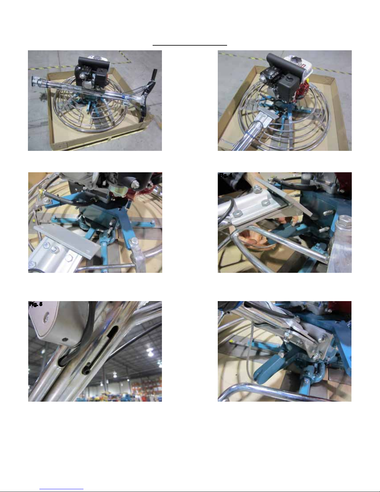
SETUP PROCEDURE
Fig. 1 Fig. 2
Step 1: Trowel shown with handle separate. (Fig. 1) Step 2: Lay handle on ring to prepare for assembly.
(Fig. 2 and 3)
Fig. 3
Fig. 4
Step 3: Install pitch control cable to yoke and install locknut loosely
(Fig. 4). If needed, turn pitch control knob counter-clockwise until the
stop screw is at the lowest position (Fig. 5).
Fig. 5 Fig. 6
Step 4: Lift and install handle to position using the supplied four sets of lockwashers and nuts.
Do not torque greater than 18ft-lb. At the yoke; tighten the locknut for pitch control cable (Fig. 6).
If the cable is too loose or tight, the pitch control range position can be moved by changing the
position of the stop screw (Fig. 5). The factory default is the middle position. Turn the pitch control
knob completely clockwise and check for maximum pitch possible. This is possible when the clearance between the yoke and underside of the gearbox is enough to pass a business card through.
375 ANNAGEM BLVD., MISSISSAUGA, ONTARIO, CANADA, L5T 3A7, 905-364-4200 FAX 905-364-4201
25 INDUSTRIAL DRIVE, KEYPORT, NEW JERSEY, USA, 07735, 732-566-6400 FAX 732-566-5444
10
CREATED: 07/04
REVISED: 06/13
Page 12
WALK-BEHIND TROWEL INSTRUCTION MANUAL
Fig. 7
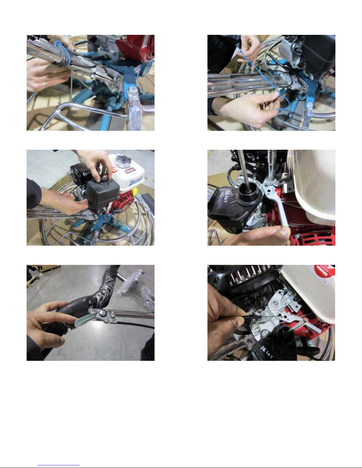
Step 5: Unwrap throttle control and engine safety shut-off wires to
prepare for their assembly. (Fig. 7 and 8)
Fig. 9 Fig. 10
Fig. 8
Step 6: Remove air lter cover and air lter. (Fig. 9) Step 7: Check for free moving engine throttle control
lever and loosen pivot nut if necessary (Fig. 10)
Fig. 11 Fig. 12
Step 8: Push handle throttle lever all the way
forward for idle position (Fig. 11). If necessary, the
Step 9: Install the throttle control wire into the
throttle control lever. (Fig. 12)
tension screw can be adjusted for smooth operation
while holding throttle position.
375 ANNAGEM BLVD., MISSISSAUGA, ONTARIO, CANADA, L5T 3A7, 905-364-4200 FAX 905-364-4201
25 INDUSTRIAL DRIVE, KEYPORT, NEW JERSEY, USA, 07735, 732-566-6400 FAX 732-566-5444
11
CREATED: 07/04
REVISED: 06/13
Page 13
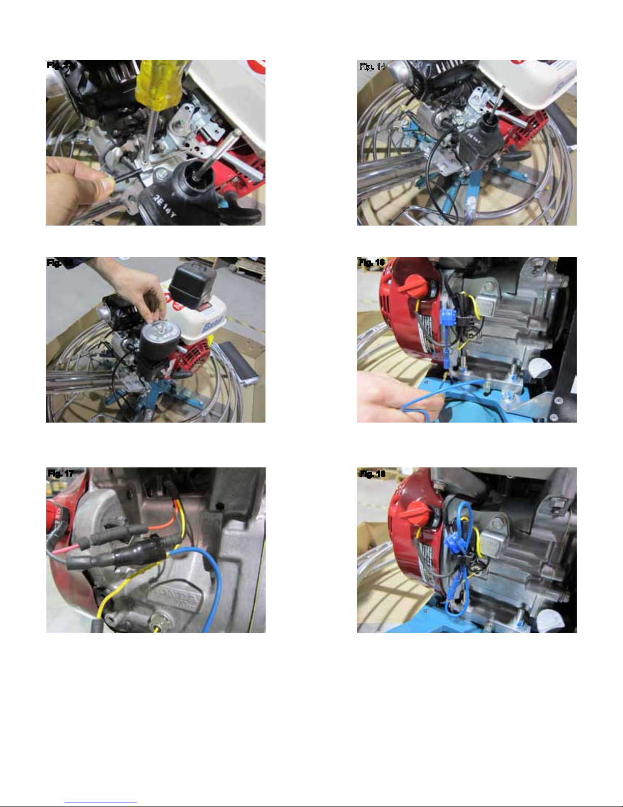
Fig. 13
WALK-BEHIND TROWEL INSTRUCTION MANUAL
Fig. 14
Step 10: Secure the wire to the cable clamp while
pushing with slight pressure forward. (Fig. 13)
Fig. 15
Step 11: Check operation of throttle control lever.
(Fig. 11 and 14)
Fig. 16
Step 12: Reinstall air lter and cover (Fig. 15) Step 13: Route engine safety shut-off wire around
engine and install. There are two types that may be
available with the machines. (Fig. 16 and 17)
Fig. 17
Fig. 18
375 ANNAGEM BLVD., MISSISSAUGA, ONTARIO, CANADA, L5T 3A7, 905-364-4200 FAX 905-364-4201
25 INDUSTRIAL DRIVE, KEYPORT, NEW JERSEY, USA, 07735, 732-566-6400 FAX 732-566-5444
12
Step 14: Wrap and secure engine safety shut-off
wire. (Fig. 18)
Step 15: Refer to Owner’s Manual before operating
the trowel.
CREATED: 07/04
REVISED: 06/13
Page 14

WALK BEHIND POWER TROWEL INSTRUCTION MANUAL
OPERATION (Floating)
When the slab has set sufficiently firm that the
operator’s footprint leaves a very slight depression on
the surface of the slab, it is ready for the floating
operation.
Under normal operating conditions the machine should
cover as much as 1000 sq. ft. in about 15 minutes. It is
recommended that a slight tension on the trowel control
cable, (but not a definite tilt), during the floating
operation will cause the machine to operate much
smoother. After the floated slab has set sufficiently, it is
ready for the finishing operation.
CAUTION:
Do not let the machine stand in one spot on the
soft cement. Lift from the slab when the floating
operation is complete.
OPERATION (Finishing)
When starting the finishing operation, never set the
trowels up over 1/4” pitch. This is important. Guiding the
machine on the slab is very simple, a slight upward lift of
the handle causes the machine to travel to the left.
Holding the handle in the neutral position, will slowly
cause the machine to spin in one spot. Slight downward
pressure on the handle causes the machine to travel to
the right. Best results are obtained by covering
approximately 4” on each turn. In other words, let the
machine move right or left, backwards or forwards,
approximately 4” with each revolution of the trowels. To
fill a hole or cut down a
hump, move the unit back and
forth over the problem area.
After the first pass over the slab, the waiting time
between operations is determined in the same manner
as if you were hand troweling. To repeat; the entire
application and action of the troweling machine in regard
to getting on the slab, and the correct pitch of the
trowels, is determined in the same manner as would be
used by a cement finisher when troweling by hand.
STARTING PROCEDURE:
Open fuel valve on gas tank. Set throttle lever to “Fast”
idle position, set choke to closed position, start engine.
Open choke slightly to prevent flooding. Move to “Open”
or “Run” position when engine is warm, increase throttle
to maximum operation position (3600 rpm).
*WARM CLIMATE
STARTING PROCEDURE: *COLD CLIMATE
Follow same procedure as above but allow longer
warm-up period – 3 to 5 minutes. In cold weather, oil is
much heavier to move and requires more time to work
its way into the moving parts. If maximum power is not
attained, allow further warm-up time. Fill fuel tank with
clean gasoline, use safety approved gas containers.
DO NOT MIX OIL WITH GASOLINE – USE UNLEADED
GAS ONLY.
STOPPING PROCEDURE
1. Throttle engine down.
2. Turn off stop switch.
LUBRICATION
1. ENGINE OIL
The long life and successful operation of any piece of
machinery is dependent on frequent and thorough
lubrication.
Before using the trowel, always check your engine for
oil. Use proper engine oil as recommended in the
engine manufacturer’s manual. Fill crankcase to
levels as recommended.
ENGINE OIL SPECIFICATIONS
All Season SAE 10W-30
2. SPIDER PLATE
There are 4 (four) grease fittings on the spider plate,
each must be greased daily. THE SPIDER PLATE
MUST BE GREASED EVERY TIME MACHINE IS
USED.
3. GEARBOX
Check the oil level sight plugs on both gearboxes
daily to ensure the oil is half way on the site glass.
Top up with Agma 8 compounded gear oil only.
Gearbox capacity 16 oz. to 19 oz. (473ml. To 562ml.)
Example: Esso/Exxon Cylesstic TK680.
4. TO CHANGE GEARBOX OIL
Place a pan beneath the drain plug to catch the oil.
Remove the drain plug and the filler plug from the
gearbox. After the oil has drained completely, replace
the drain plug and tighten. Fill the gearbox through
the filler plug with 16 oz. to 19 oz. (473ml. To 562ml.)
of Agma 8 compounded gear oil. Replace the filler
plug and tighten.
375 ANNAGEM BLVD., MISSISSAUGA, ONTARIO, CANADA, L5T 3A7, 905-364-4200 FAX 905-364-4201
375 ANNAGEM BLVD., MISSISSAUGA, ONTARIO, CANADA L5T 3A7, 905-364-4200 FAX 905-364-4201
25 INDUSTRIAL DRIVE, KEYPORT, NEW JERSEY, USA, 07735, 732-566-6400 FAX 732-566-5444
CREATED: 07/04
11
13
REVISED: 05/10
06/13
Page 15

WALK BEHIND POWER TROWEL INSTRUCTION MANUAL
STORAGE
The following steps should be taken to prepare your
Walk-Behind Power Trowel for extended storage.
1. Close fuel shut off valve.
2. Siphon excess gasoline from tank.
3. Start engine until it stops from lack of fuel. This will
use up all the fuel in the carburetor and prevent
formation of deposits due to evaporation of fuel.
4. Remove spark plug and pour 2 oz. of SAE-30 or
SAE-40 motor oil into the cylinder. Slowly crank the
engine 2 or 3 times to distribute the oil throughout
the cylinder. This will help prevent rust during
storage. Replace spark plug.
5. Store the unit in an upright position in a cool, dry,
well ventilated area.
MAINTENANCE
Maintaining your Walk-Behind Power Trowel will insure
long life to the machine and its components.
AIR CLEANER - Keep air filter clean at all times. Wash
away dust and debris using a non-oil based cleaning
solvent. Let the filter dry before re-installing.
LUBRICATION – Check engine oil regularly. Use
proper engine oil as recommended. See previous
chart. Fill crankcase to levels as recommended in
manufacture’s engine manual.
SPARK PLUG
regularly. A fouled, dirty or
hard starting and poor engine performance. Set spark
plug gap to recommended clearance. Refer to engine
manual.
BELT TENSION – IMPORTANT!
If there is excessive belt play, there will be a decrease
in the power transmission capability which could lead to
premature wear and failure of the belt. The normal belt
play should be 1/2” to 5/8” which is attained by
depressing one side of the belt at the mid-point of the
span between pulleys. Tighten all engine mount
fasteners.
– Check and clean spark plugs
carboned spark plug causes
CHART FOR MINIMUM WIRE SIZE OF EXTENSION CORD
Nameplate AMPS CORD LENGTH
25’ 50’ 100’ 150’
0-6 18 AWG 16 AWG 16 AWG 14 AWG
6-10 18 AWG 16 AWG 14 AWG 12 AWG
10-12 16 AWG 16 AWG 14 AWG 12 AWG
12-16 14 AWG 12 AWG (NOT RECOMMENDED)
375 ANNAGEM BLVD., MISSISSAUGA, ONTARIO, CANADA, L5T 3A7, 905-364-4200 FAX 905-364-4201
375 ANNAGEM BLVD., MISSISSAUGA, ONTARIO, CANADA L5T 3A7, 905-364-4200 FAX 905-364-4201
25 INDUSTRIAL DRIVE, KEYPORT, NEW JERSEY, USA, 07735, 732-566-6400 FAX 732-566-5444
CREATED: 07/04
12
14
REVISED: 05/10
06/13
Page 16
WALK-BEHIND TROWEL INSTRUCTION MANUAL
ELECTRIC POWER TROWEL OPERATION
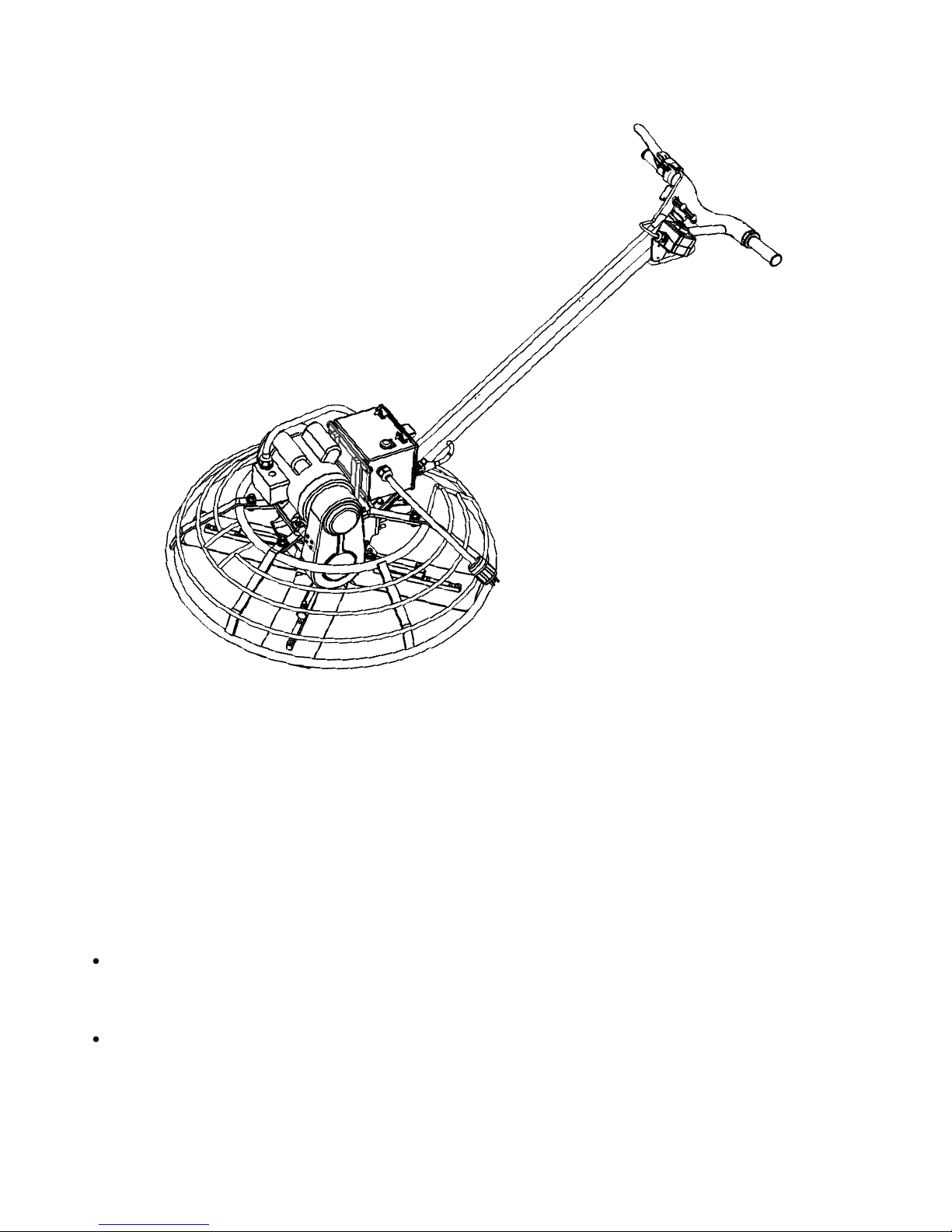
The electric models of Bartell Power Trowels require appropriate power sources, connections,
extension cords, and surge protection. Bartell Morrison Inc. is not responsible for damage to person
or property due to improper use or setup of an Electric Power Trowel. Select your power supply and
other provisions based on the specific type of trowel being operated.
While the Electric Power Trowel has internal surge protection to protect the motor, electronics, and
operator from internal power surges, the power supply should be equipped with an appropriate
breaker to protect the equipment and personnel on the job site from potential harm from a damaged
power supply cord.
The following safety precautions should always be observed when operating Bartell Electric Power
Trowels, in addition to the stated precautions for regular power trowels:
The operator is responsible for the protection of the electrical power supply cord. Do not let the
cord come into contact with the trowel blades under any circumstances. If the cord does touch the
blades, immediately power down the trowel, unplug the electrical supply, and inspect the cord for
damage. Cords with damaged insulation should be replaced immediately.
If the trowel blades stick or jam a surge will be created, tripping the external breaker. Avoid starting
the trowel after sitting on green concrete for extended periods without first breaking the bond or
applying some water to the surface for lubrication. Avoid hitting obstacles with the blades as this
can cause physical damage to the blades, transmission, or trip the breaker.
375 ANNAGEM BLVD., MISSISSAUGA, ONTARIO, CANADA, L5T 3A7, 905-364-4200 FAX 905-364-4201
375 ANNAGEM BLVD., MISSISSAUGA, ONTARIO, CANADA L5T 3A7, 905-364-4200 FAX 905-364-4201
25 INDUSTRIAL DRIVE, KEYPORT, NEW JERSEY, USA, 07735, 732-566-6400 FAX 732-566-5444
CREATED: 07/04
15
13
REVISED: 05/10
06/13
Page 17
WALK BEHIND POWER TROWEL INSTRUCTION MANUAL
While the trowel should be cleaned daily, and the electronic components are splash-resistant,
avoid spraying water or other liquids directly on the motor, starter box, or handle controls, as this
can damage the electronics. Never immerse the trowel in water. If water intrusion into the
electronics is suspected, have the trowel inspected by an authorized BMi representative before
operating.
Do not attempt to disable the electric safety switch on the right handle of the trowel.
Do not pull the trowel by the safety switch housing.
Always unplug the trowel for storage or transportation.
SETTING UP THE ELECTRIC POWER TROWEL
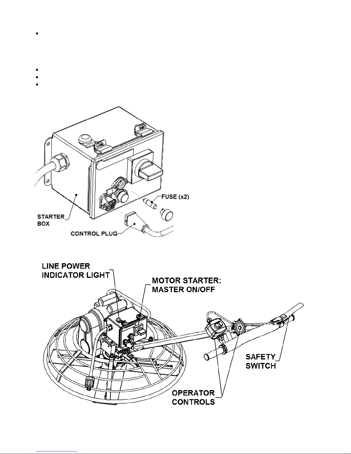
The Bartell Electric Power Trowel
ships without the handle attached.
When installing the handle, ensure
that the control plug at the lower end
of the handle is plugged into the
receptacle at the lower left of the
motor starter box and retained with
the clip.
The box is protected with two (2)
timed fuses. If your trowel will not
start, and the breakers at the line
and starter box are ok, then you
may need to replace the fuses.
STARTING THE ELECTRIC POWER TROWEL
375 ANNAGEM BLVD., MISSISSAUGA, ONTARIO, CANADA, L5T 3A7, 905-364-4200 FAX 905-364-4201
375 ANNAGEM BLVD., MISSISSAUGA, ONTARIO, CANADA L5T 3A7, 905-364-4200 FAX 905-364-4201
25 INDUSTRIAL DRIVE, KEYPORT, NEW JERSEY, USA, 07735, 732-566-6400 FAX 732-566-5444
CREATED: 07/04
16
14
REVISED: 05/10
06/13
Page 18
WALK BEHIND POWER TROWEL INSTRUCTION MANUAL
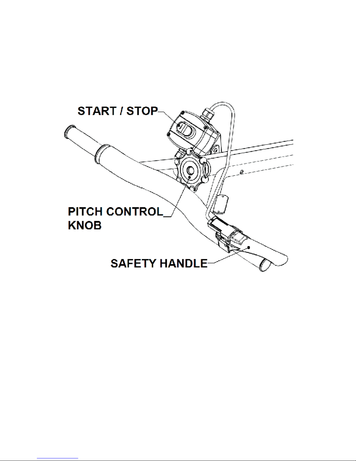
1. Plug the trowel into the electrical supply. If the line power is on, the green power indicator
lamp on the top of the trowel will glow.
2. Turn the master starter switch clockwise to the ON (vertical) position. If it will not stay in the
ON position, then turn it fully counterclockwise to the OFF position and try again. The internal
breaker of the starter box will not let the master switch be turned on until it has been reset by
turning it off.
3. With the master switch ON, stand at the operator position behind the handle. The motor will
not start until the safety handle is fully depressed, and it will immediately stop if the safety
handle is released. Squeeze the safety handle with your right hand until it is fully depressed,
and hold this for the duration of operation.
4. Brace your hip against the shield pad on the handle for better control. Bartell Electric Power
Trowels operate at a constant speed which is achieved immediately after startup, so there will
be some kick. With your left hand, press the green start button. The trowel will immediately
begin to turn.
NOTE: If the trowel appears to hesitate or the motor strains for more than 3 seconds, release the
safety handle and inspect the blades for any obstructions or bonding to the concrete. Clear the
obstacle and try again.
5. To stop the trowel, simply release
release the handles until the blades have stopped rotating. If leaving the trowel for any
extended period, turn the master switch to the OFF position.
375 ANNAGEM BLVD., MISSISSAUGA, ONTARIO, CANADA, L5T 3A7, 905-364-4200 FAX 905-364-4201
375 ANNAGEM BLVD., MISSISSAUGA, ONTARIO, CANADA L5T 3A7, 905-364-4200 FAX 905-364-4201
25 INDUSTRIAL DRIVE, KEYPORT, NEW JERSEY, USA, 07735, 732-566-6400 FAX 732-566-5444
the safety handle or press the red stop button. Do not
CREATED: 07/04
17
15
REVISED: 05/10
06/13
Page 19
WALK BEHIND POWER TROWEL INSTRUCTION MANUAL
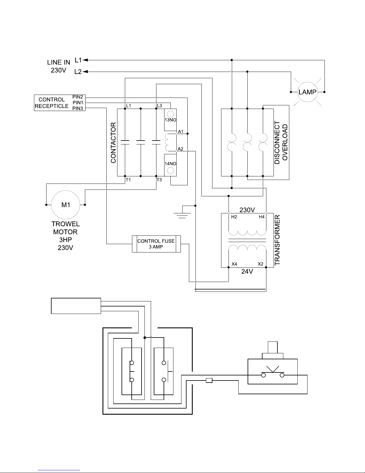
ELECTRIC POWER TROWEL WIRING DIAGRAM:
CONTROL
PLUG
PIN2
PIN1
PIN3
G
W
BL
K
375 ANNAGEM BLVD., MISSISSAUGA, ONTARIO, CANADA, L5T 3A7, 905-364-4200 FAX 905-364-4201
375 ANNAGEM BLVD., MISSISSAUGA, ONTARIO, CANADA L5T 3A7, 905-364-4200 FAX 905-364-4201
25 INDUSTRIAL DRIVE, KEYPORT, NEW JERSEY, USA, 07735, 732-566-6400 FAX 732-566-5444
W
1 3
STOP
START
2 4
CONTROL BOX
DEADMANOFF
BL
BL
K
BR
COM
SAFETY SWITCH
NO
CREATED: 07/04
16
18
REVISED: 05/10
06/13
Page 20
WALK BEHIND POWER TROWEL INSTRUCTION MANUAL
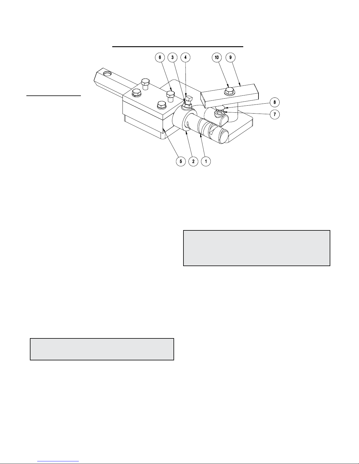
TROWEL ARM ADJUSTMEN T FIXTURE
PART #20801
Ex: Unit 36” (B436)
1)10810A – Trowel arm
2)10817A – Lift lever
3)10808 – Jam nut
4)10809 – Set screw
5)10824 – Block top
6)10507 – Bolt
7)10808 – Jam nut
8)10807 – Carriage bolt
9)10832 – Adjustment bar
10) 10507 – Bolt
Figure
The trowel arm adjustment fixture (20801) is reversible.
By rotating the arm clamping fixture and the ring bolt,
both left hand and right hand trowel arms may be
adjusted. Before attempting adjustment, determine
whether the trowel arm is right handed or left handed.
When adjusting left hand trowel arms use the side of the
fixture marked “L”. When adjusting right hand trowels
arms use the opposite side. The adjustment bar will be
set on “36” for the Walk-behind trowel arm.
ADJUSTMENT PROCEDURE
1. Remove all trowel arm assemblies (1 & 2 arm and
attached lift lever) from suspected maladjusted spider
plate.
2. Remove lift lever (2) from trowel arm (1) by first
loosening jam nut (3) then square head screw (4). If
upon inspection (method left to discretion of
serviceman) any trowel arm (1) is found to be in a
bent condition, it must either be brought back to its
original straight condition (method left to the
serviceman’s discretion) or replaced with new part.
3. Replace lift levers (2) on new or straightened arms
(1) by reversing procedure as described above.
NOTE: IT IS IMPORTANT THAT WHEN TIGHT ENING SQUARE HEAD NUT (4), IT SEATS ITSELF
SECURELY INTO DIMPLE MACHINED IN ARM.
4. Place trowel arm assembly (1 and 2) in fixture (5)
with lift lever (2) butting up against fixture. Clamp in
place with bolts
5. Loosen locknut (7) and screw carriage bolt (8) down
to full depth allowable. This will provide for ample
clearance to swing precision ground adjustment bar
(9) over head of carriage bolt.
(6).
5a.
Adjustment bar (9) is stamped for appropriate size of
machine. Swing appropriate side directly over carriage
bolt (8) and secure in place with bolt (10).
6. Adjust carriage bolt (8) upwards until contact is made
with adjustment bar (9); holding carriage bolt in
position with one wrench, tighten locknut (7) to secure
in position with second wrench.
NOTE: IT IS VITALLY IMPO RTANT TO ENSURE
THAT ONCE THE CARRIAGE BOLT IS ADJUSTED
TO THE CORRECT HEIGHT, IT DOES NOT MOVE
BEFORE, OR DURING THE TIGHTENING OF
LOCKNUT.
7. This same procedure is to be followed with ALL arms
from spider plate assembly, and will ensure correct
and exact adjustment.
TROWEL ARM ADJUSTMENT SCREW
The trowel arm adjustment screw is to be used for field
adjustment of blade level, in the event of a damaged
trowel arm, to enable completion of the job. At the end of
the job repairs should be made to eliminate the damage.
When assembling trowel blades to trowel arms, the
adjustment screw should NEVER protrude below the
under-side surface of a trowel arm.
If the adjustment screw is not flush with the underside of
the trowel arm, then this will cause the power trowel to
bounce and vibrate especially at high speed. This will
also cause the trowel blades to leave an uneven finish to
the concrete due to
another.
Make certain that the adjusting screw is held firmly in
place while tightening the bolt which secures the blade to
the trowel arm.
the blades not being level to one
375 ANNAGEM BLVD., MISSISSAUGA, ONTARIO, CANADA, L5T 3A7, 905-364-4200 FAX 905-364-4201
375 ANNAGEM BLVD., MISSISSAUGA, ONTARIO, CANADA L5T 3A7, 905-364-4200 FAX 905-364-4201
25 INDUSTRIAL DRIVE, KEYPORT, NEW JERSEY, USA, 07735, 732-566-6400 FAX 732-566-5444
CREATED: 07/04
17
19
REVISED: 05/10
06/13
Page 21

WALK BEHIND POWER TROWEL INSTRUCTION MANUAL
TROUBLESHOOTING
WON’T START
• Throttle fully open
• Hand lever wire broken
• No gas
• Dirty gas
• Gas filter plugged
• Gas line plugged
• Hole in gas line
• Gas supply valve turned off
• Dead-man safety switch
• Safety switch wire or connectors not making
good contact
• Other engine problems (Refer to engine manual)
STARTS BUT NO HIGH SPEED
• Engine problems
• Throttle cable broken or seized
• Throttle lever and connectors loose or out of
adjustment
• Clutch shoes worn
STARTS AT HIGH SPEED, WON’T SLOW DOWN
• Same
ENGINE WON’T STOP
• Safety switch, wire or connectors not making
ENGINE STARTS BUT WON’T TU RN TROWELS AT
ANY SPEED
• Clutch seized
• No weights or broken clutch
• Wrong belt
• Broken or missing key
- Clutch
- Pulley
- Worm gear (countershaft)
- Main gear
- Spider plate
• Gearbox seized
TROWELS TURN, ENGINE AT IDLE
• Idle too fast
• Belt too tight
• Clutch seized
• Pulley out of alignment
TROWELS BLADES WEARING UNEVENLY
• Spider plate seized
• Arms bent
• Adjusting screws (carriage bolts) incorrectly set
as above
good contact
MACHINE JUMPS ON F
LOOR
• Concrete hardened on bottom of spider plate
• Trowels unevenly worn
• Spider plate seized
• Spider plate loose
• Trowel arms bent
• Adjusting screws (carriage bolts) incorrectly set
use spider plate adjustment jig (pg,13)
• Mainshaft bent
PITCH CONTROLS WILL NOT OPERATE BLADES
• Cable broken or out of adjustment
• Slot screw missing (under-side of handle)
• Spider plate seized
• Pressure plate and/or yoke arm broken or badly
worn
• Hand crank a
djuster malfunctioning
BELT WEARING RAPIDLY
• Belt adjusted improperly
• Pulley out of alignment
• Wrong belt/defective belt
• Clutch sticking
• Gearbox seizing
OIL LEAKS
a) Top of gearbox
• Engine leaks
• Relief valve broken
• Too much oil in gearbox
• Set screw missing in cover
b) Between end cap and gearbox (recoil side)
• “O” ring damaged
• End cap not tight
c) At mainshaft or countershaft
• Relief valve seized
• Shaft and/or seal worn
TROWEL BLADES WILL NOT TURN
• Yoke arm broken
Key sheared
•
SPIDER PLATE HARD TO GREASE
• Fittings plugged
• Cement in grease grooves of arms
• Grease fittings too tight
375 ANNAGEM BLVD., MISSISSAUGA, ONTARIO, CANADA, L5T 3A7, 905-364-4200 FAX 905-364-4201
375 ANNAGEM BLVD., MISSISSAUGA, ONTARIO, CANADA L5T 3A7, 905-364-4200 FAX 905-364-4201
25 INDUSTRIAL DRIVE, KEYPORT, NEW JERSEY, USA, 07735, 732-566-6400 FAX 732-566-5444
CREATED: 07/04
18
20
REVISED: 05/10
06/13
Page 22

WALK BEHIND POWER TROWEL INSTRUCTION MANUAL
WALK BEHIND POWER TROWEL INSTRUCTION MANUAL
SPECIFICATIONS
WALK-BEHIND TROWEL
Model Path
Power Source
(gas option)
Float Blade
Size
Finish
Trowel Size
Combination
Blade Size
Float
Pan
Operating
Weight
B430
30"
(75 cm)
5.5 hp Honda OHV N/A
6” x 10-1/2"
(15 x 27 cm)
N/A N/A
Up to 165 lb.
(75 kg)
B436
36"
(90 cm)
5.5 hp Honda OHV
9 hp Honda OHV
10” x 14"
(25 x 36 cm)
6” x 14"
(15 x 36 cm)
8” x 14"
(20 x 36 cm)
38 ½"
(98 cm)
Up to 165 lb.
(75 kg)
B436E
36"
(90 cm)
3 hp, 230V, 1 Phase
Electric Motor
10” x 14"
(25 x 36 cm)
6” x 14"
(15 x 36 cm)
8” x 14"
(20 x 36 cm)
38 ½"
(98 cm)
Up to 165 lb.
(75 kg)
B440
40"
(100 cm)
9 hp Honda OHV
10” x 14"
(25 x 36 cm)
6” x 14"
(15 x 36 cm)
8” x 14"
(20 x 36 cm)
NA
Up to 165 lb.
(75 kg)
B446
46"
(120 cm)
9 hp Honda OHV
9 hp Subaru OHV
11 hp Honda OHV
11 hp Subaru OHV
10” x 18"
(25 x 46 cm)
6” x 18"
(15 x 46 cm)
8” x 18"
(20 x 46 cm)
48 ½"
(123 cm)
Up to 245 lb.
(110 kg)
WALK-BEHIND TROWEL
Model Path
Model Path
B430
B430
B436
B436
B436E
B446
B440
B446
Blade Speed (RPM)
Engine Speed (RPM)
Clutch Type
Variable Speed
Gearbox Oil
Gearbox Oil Capacity
Blade Speed (RPM)
Engine Fuel
Engine Speed (RPM)
Engine Oil Alert
Clutch Type
Cooling
Variable Speed
Starting
Gearbox Oil
Dead-man Safety Switch
Gearbox Oil Capacity
Fuel Capacity (approximately)
Engine Fuel
Running Time (approximately)
Engine Oil Alert
Number of Blades 4
Cooling
Engine Acoustic Power Lwa (dB)
Starting
Engine Acoustic Pressure Lpa (Db)
Dead-man Safety Switch
Level of Vibration
Fuel Capacity (approximately)
Vibration value on the handle
Running Time (approximately)
Options Oil-Bath Spider Assembly
36”
30"
(90cm)
(75 cm)
36”
36"
(90cm)
(90 cm)
46”
36"
(90 cm)
(120cm)
40"
(100 cm)
46"
(120 cm)
Power Source
Power Source
(gas option)
(gas option)
Honda GX160
Honda GX270
5.5 hp Honda OHV N/A
3hp, 230V, 1 Phase
5.5 hp Honda OHV
Electric Motor
9 hp Honda OHV
Honda GX160
Honda GX270
3 hp, 230V, 1 Phase
Honda GX340
Honda GX390
9 hp Honda OHV
9 hp Honda OHV
9 hp Subaru OHV
11 hp Honda OHV
11 hp Subaru OHV
Electric Motor
Number of Blades 4
Engine Acoustic Power Lwa (dB)
Engine Acoustic Pressure Lpa (Db)
Level of Vibration
Vibration value on the handle
Options Oil-Bath Spider Assembly
Power rating conforming to DIN 6270 & ISO 3048/1 Std.
RPM results may vary by engine option.
Power rating conforming to DIN 6270 & ISO 3048/1 Std.
RPM results may vary by engine option.
375 ANNAGEM BLVD., MISSISSAUGA, ONTARIO, CANADA, L5T 3A7, 905-364-4200 FAX 905-364-4201
375 ANNAGEM BLVD., MISSISSAUGA, ONTARIO, CANADA L5T 3A7, 905-364-4200 FAX 905-364-4201
25 INDUSTRIAL DRIVE, KEYPORT, NEW JERSEY, USA, 07735, 732-566-6400 FAX 732-566-5444
SPECIFICATIONS
Float Blade
Float Blade
Size
Walk Behind Trowel (GASOLINE)
Walk Behind Trowel (GASOLINE)
Size
10” x 14”
(25 x 36cm)
10” x 14”
10” x 14"
(25 x 36cm)
(25 x 36 cm)
10” x 18”
10” x 14"
(25 x 36 cm)
(25 x 46cm
10” x 14"
(25 x 36 cm)
10” x 18"
(25 x 46 cm)
Finish
Trowel Size
Finish
Trowel Size
6” x 14”
6” x 10-1/2"
(15 x 36cm)
(15 x 27 cm)
6” x 14”
6” x 14"
(15 x 36cm)
(15 x 36 cm)
6” x 18”
6” x 14"
(15 x 36 cm)
(15 x 46cm)
6” x 14"
(15 x 36 cm)
6” x 18"
130-160
(15 x 46 cm)
3600
Centrifugal
Yes
Agma 8 compounded gear oil
16 oz. (473 ml), 19 oz. (562 ml)
130-160
Gasoline – Unleaded
3600
Yes
Centrifugal
Air
Yes
Recoil Starter - Manual
Agma 8 compounded gear oil
Yes
16 oz. (473 ml), 19 oz. (562 ml)
3 Gal. (12.5 L)
Gasoline – Unleaded
2 ½ hours
Combination
Combination
Blade Size
Blade Size
8” x 14”
(20 x 36cm)
8” x 14”
(20 x 36cm)
(20 x 36 cm)
8 x 18”
(20 x 36 cm)
(20 x 46cm)
(20 x 36 cm)
(20 x 46 cm)
Yes
Air
97-103
Recoil Starter - Manual
82-86
Yes
1.1-1.5
3 Gal. (12.5 L)
7.0 aw
2 ½ hours
Insta-Pitch Lever
97-103
Hoist Hook
82-86
Carry Bar
1.1-1.5
Folding Handle
7.0 aw
Insta-Pitch Lever
Hoist Hook
Carry Bar
Folding Handle
21
19
Float
Pan
36 1/2”
N/A N/A
8” x 14"
8” x 14"
8” x 14"
8” x 18"
(93 cm)
38 1/2”
(98 cm)
48 1/2”
(123 cm)
(98 cm)
(98 cm)
(123 cm)
Operating
Float
Pan
38 ½"
Weight
Up to 185 lb.
(75 kg)
Up to 165 lb.
(75 kg)
Up to 240 lb.
38 ½"
48 ½"
(109 kg)
NA
CREATED: 07/04
REVISED: 05/10
Operating
Weight
Up to 165 lb.
(75 kg)
Up to 165 lb.
(75 kg)
Up to 165 lb.
(75 kg)
Up to 165 lb.
(75 kg)
Up to 245 lb.
(110 kg)
06/13
Page 23

WALK BEHIND POWER TROWEL INSTRUCTION MANUAL
Declaration of Conformity / Certificat de conformité / Gelijkvormigheids certificaat
Declaración de Conformidad/Declaração de Conformidade/Dichiarazione Di Conformita
We: Bartell Morrison Inc. Bartell Morrison (USA) LLC.
375 Annagem Blvd. 12 Industrial Drive
Mississauga, Ontario, Canada Keyport, New Jersey, United States of America
L5T 3A7 07735
Tel: 905-364-4200 Fax: 905-364-4201 Tel: 732-566-5400 Fax: 732-566-5444
Declare under our sole responsibility that the product to which this declaration relates is in conformity with the
following standard(s) or other normative documents.
Déclarons sous notre responsabilité que le produit cette déclaration est conforme aux normes suivantes ou d’autres
documents habituels.
Verklaren onder onze verantwoordelijkheid dat het product naar welke de verklaring verwijst conform de volgende
standaards of anders gebruikelijke documenten is.
Declaramos bajo nuestra única responsabilidad que el producto en lo que esta declaración concierne, es conforme
con la siguiente normativa u otros documentos.
Declara sob sua responsabilidade que o produto a quem esta declaração interessar, está em comformidade com
os seguintes documentos legais ou normas directivas.
Dichiariamo sotto la ns. unica responsibilita che il prodotto al quale questa dichiarazione si riferisce, è fabbricato in
conformità ai seguenti standard e documenti di normative.
EN 349:1993 Safety of Machinery - Minimum gaps to avoid crushing of parts of the human body.
EN 418:1993
EN 12100-1:2003
EN 12100-2:2003
EN ISO 4872:1978
EN ISO 5349-1:2001
EN ISO 5349-2:2001
Following the provisions of Directive(s):
Suivant les directive(s) déterminées:
Volgens de vastgestelde richtlijnen:
Siguiendo las directiva(s):
No sequimento das clausulas da Directiva(s):
Seguendo quanto indicato dalla Direttiva(s):
98/37/EC Machinery Directive
2000/14/EC Noise Directive
2001/95/EC General Product Safety Directive
2002/95/EC Reduction of Hazardous Waste Directive
Safety of Machinery - Emergency stop equipment, functional aspects - Principles for
design
Safety of Machinery - Basic Concepts, general principles for design - Part 1: Basic
Terminology, methodology
Safety of Machinery - Basic Concepts, general principles for design
Principles
Acoustics - Measurement of Airborne noise emitted by construction equipment intended
for outdoor use - Method for determining compliance with noise limits.
Mechanical vibration. Measurement and evaluation of human exposure to handtransmitted vibration. General requirements
Mechanical vibration. Measurement and assessment of human exposure to handtransmitted vibration. Practical guidance for measurement at the workplace.
25
- Part 2: Technical
375 ANNAGEM BLVD., MISSISSAUGA, ONTARIO, CANADA, L5T 3A7, 905-364-4200 FAX 905-364-4201
375 ANNAGEM BLVD., MISSISSAUGA, ONTARIO, CANADA L5T 3A7, 905-364-4200 FAX 905-364-4201
25 INDUSTRIAL DRIVE, KEYPORT, NEW JERSEY, USA, 07735, 732-566-6400 FAX 732-566-5444
CREATED: 07/04
22
20
REVISED: 05/10
06/13
Page 24
WALK BEHIND POWER TROWEL INSTRUCTION MANUAL
Technical Characteristics:
Caractéristiques techniques:
Technisch gegevens:
Características Técnicas:
Caracteristicas
às di tecnico:
Qualit
Model
Modéle
Type
Modelo
Modelo
Modello
Lbs
B436 Walk Behind Power Trowel 125
The Technical Construction file is maintained at:
Les fiches techniques de construction sont gardées à:
Het technische constructie document wordt bewaard te:
El archivo técnico de construcción se mantiene en:
O arquivo técnico de construção é mantido no (a):
L’originale dossier tecnico di construzione è conservato presso:
The authorized representative is:
Le représentant autorisé est:
Gemachtigd vertegenwoordiger is:
La representación autorizada es:
O representante autorizado é:
Il rappresentate autorizzato:
Signature of Authorized Person:
Signature de la personne autorisée:
Handtekening van gemachtigd persoon:
Firma de la persona autorizada:
Assinatura de pessoa autorizada:
Firma della persona autorizzata:
Typed name of Authorized Person:
Nom dactlyographié de la personne autorisée:
Getypte naam van gemachtigd persoon:
Nombre de la persona autorizada:
Nome datilografado da pessoa autorizada:
Nome della persona autorizzata:
Title of Authorized Person:
Titre de la personne autorisée:
Functie van gemachtigd persoon:
Cargo de la persona autorizada:
Titulo da pessoa autorizada:
Posizione della persona autorizzata:
Date and place of issue:
Date et place d’émission:
Datum en plaats van afgifte:
Fecha y lugar de emision:
Data e lugar de emissão:
Data e luogo di emissione:
Técnicas:
Noise Level
Puissance acoustique
Geluidniveau
Nivel Sonoro
Nivel del Ruido
Potenza Acustica
Lwa
(dB)
98 99 1.5
MachineSerial Number
Numéro de Série machine
Serienummer machine
Máquina número de série
Numero de serie da maquina
Numero di seria la macchina
Pressure level
Pression acoustique
Geluidsdrukniveau
Nivel Acustico
Pressão Acústica
Pressione Acustica
Lpa
(Db)
Vibration level
Niveau de vibration
Vibratieniveau
Nivel de Vibracion
Nivel de Vibração
Livello di Vibrazione
Engine Serial Number
Numéro de Série moteur
Serienummer motor
Motor número de série
Numero de serie do motor
Numero di seria la motore
a
hv
(m/s2)
Bartell Morrison Inc.
375 Annagem Blvd.
Mississauga, Ontario, Canada
L5T 3A7
Telephone: 905-364-4200
Facsimile: 905-364-4201
Mr.Richard Stanley
Mr. Robert Leggitt
V.P. Operations
Manager - Engineering
Bartell Morrison Inc.
375 Annagem Blvd.
Mississauga, Ontario, Canada
L5T 3A7
Telephone: 905-364-4188
905-364-4185
Facsimile: 905-364-4202
Richard Stanley
Robert S. Leggitt
V.P. Operations
Manager - Engineering
03.06.2013
05.03.2010
Mississauga, Ontario, Canada
Weight
Masse
Gewicht
Masa
Massa
Massa
(56.8)
(kg)
375 ANNAGEM BLVD., MISSISSAUGA, ONTARIO, CANADA L5T 3A7, 905-364-4200 FAX 905-364-4201
23
21
CREATED: 07/04
REVISED: 05/10
08/12
Page 25

WALK BEHIND POWER TROWEL INSTRUCTION MANUAL
NOTES
375 ANNAGEM BLVD., MISSISSAUGA, ONTARIO, CANADA, L5T 3A7, 905-364-4200 FAX 905-364-4201
375 ANNAGEM BLVD., MISSISSAUGA, ONTARIO, CANADA L5T 3A7, 905-364-4200 FAX 905-364-4201
25 INDUSTRIAL DRIVE, KEYPORT, NEW JERSEY, USA, 07735, 732-566-6400 FAX 732-566-5444
22
24
CREATED: 07/04
REVISED: 05/10
06/13
Page 26

WALK BEHIND POWER TROWEL INSTRUCTION MANUAL
375 ANNAGEM BLVD., MISSISSAUGA, ONTARIO, CANADA, L5T 3A7, 905-364-4200 FAX 905-364-4201
375 ANNAGEM BLVD., MISSISSAUGA, ONTARIO, CANADA L5T 3A7, 905-364-4200 FAX 905-364-4201
25 INDUSTRIAL DRIVE, KEYPORT, NEW JERSEY, USA, 07735, 732-566-6400 FAX 732-566-5444
25
23
CREATED: 07/04
REVISED: 05/10
06/13
Page 27

BARTELL MORRISON
BARTELL MORRISON INC.
375 Annagem Blvd.
Mississauga, Ontario, Canada
L5T3A7
Toll Free: 866-501-1683
Local: 905-364-4200
Fax: 905-364-4202
www.bartellmorrison.com
BARTELL MORRISON (USA) LLC.
12 Industrial Drive.
25
Keyport, New Jersey, USA
07735
Toll Free: 888-999-1570
Local: 732-566-5400
Fax: 732-566-5444
www.bmiamerica.com
 Loading...