

Page 1
TR
U
SER
G
UIDE
Tyre Pressure Monitoring
System Tool
TECH700 Software version v57.0.3.2
2018
Page 2

T E C H 7 0 0 User Guide 2 0 1 8
F
OREWORD
Dear customer
Thank you for having chosen one of our tools. We are certain that it will
give the utmost satisfaction and be a great help on the job with Tyre
Pressure Monitoring Systems.
Please become fully familiar with the instructions in this user’s manual. It
should be kept ready to hand for consultation whenever required.
The TECH700 is a test and diagnostics tool for Truck and Bus Tyre
Pressure Monitoring Systems. It is designed for future updating and
extension with new functions and vehicle coverage.
CE COMPLIANCE
Type Designation: TECH700
Description/Intended Use: Hand Held Tyre Pressure Measurement Tool/used to activate, decode data
from, and display information about tyre pressure monitoring devices for Trucks and Buses.
Hereby, Bartec Auto ID declares that the product referenced above is in compliance with the
essential requirements of Directive 1999/5/EC, on the approximation of the laws of the member
states relating to Directive 1999/5/EC.
2 | P a g e
Page 3

T E C H 7 0 0 User Guide 2 0 1 8
P a g e | 3
Page 4

T E C H 7 0 0 User Guide 2 0 1 8
T
ABLE OF CONTENTS
Foreword .................................................................................. 2
Table Of Contents ................................................................... 4
Important Notices .................................................................. 5
Safety Precautions .................................................................. 7
Kit Components .................................................................... 10
Tool Layout ............................................................................ 11
Menu Navigation .................................................................. 12
Tool Positioning .................................................................... 14
Tool Connections/Charging Tool ........................................ 15
Power ON/OFF Sequence ..................................................... 16
Home Menu ........................................................................... 17
Vehicle Check ........................................................................ 19
Possible Reading Scenarios ................................................. 24
View Sensor Data .................................................................. 25
Delete Sensor Data ............................................................... 25
Settings .................................................................................. 26
Results Audit System ............................................................ 27
Technical Specification......................................................... 29
4 | P a g e
Page 5

T E C H 7 0 0 User Guide 2 0 1 8
I
MPORTANT NOTICES
SAFETY DEFINITIONS
All Danger, Warning, Important, and Note messages must be followed for your safety.
These safety messages are in the following formats:
DANGER: Means you may risk possible loss of life.
WARNING: Means you may risk possible bodily harm.
CAUTION: Means you risk damage to the vehicle or the tool.
These safety messages cover situations Bartec Auto ID is aware of. Bartec Auto ID cannot
know, evaluate and advise you as to all the possible hazards. You must be certain that any
conditions or service procedures encountered do not jeopardize your personal safety.
COPYRIGHT
No part of this manual may be reproduced, stored in a retrieval system or transmitted, in any
form or by any means, electronic, mechanical, photocopying, recording, or otherwise,
without the prior written permission of Bartec Auto ID.
DISCLAIMER
P a g e | 5
Page 6

T E C H 7 0 0 User Guide 2 0 1 8
All information, illustrations, and specifications contained in this technical instruction manual
are based on the latest information available at the time of publication. The right is reserved
to make changes at any time without obligation to notify any person or organization of such
revisions or changes. Further, Bartec Auto ID shall not be liable for errors contained with the
furnishing, performance or use of this material.
6 | P a g e
Page 7

T E C H 7 0 0 User Guide 2 0 1 8
S
AFETY PRECAUTIONS
Read carefully the installation, operating and maintenance instructions in the Operator’s
manual.
Do not allow unqualified people to use this equipment. This will prevent injury to people and
damage to the equipment.
The work place must be dry, sufficiently lit and well ventilated.
Do not forget that breathing carbon monoxide (odourless) can be very dangerous and even
fatal.
When working on the vehicle:
• Wear suitable clothing and act in such a way as to prevent industrial accidents.
• Before starting, check to be certain the gear shift is in neutral (or in PARK (P) if the
transmission is automatic) and put the handbrake on and check to be sure the wheels
are completely locked.
• Do not smoke or use naked flames when working on a vehicle.
• Wear safety glasses to protect your eyes from dirt, dust or metal chips.
P a g e | 7
Page 8

T E C H 7 0 0 User Guide 2 0 1 8
Disposing of equipment
• Do not dispose of this equipment as miscellaneous solid waste but arrange to have
collected separately.
• The re-use or correct recycling of electronic equipment (EEE) is important in order to
protect the environment and human health.
• In accordance with European Directive WEEE 2002/96/EC, special disposal points are
available for waste electrical and electronic equipment.
• Public administrators and producers of electrical and electronic equipment are
involved in facilitating the re-use and recovery of waste electrical and electronic
equipment through these collection activities and use of appropriate planning
arrangements.
•
Unauthorised disposal of waste electrical and electronic equipment is punishable by
law with appropriate penalties.
Disposing of batteries
• The TECH700 contains a Lithium Polymer rechargeable battery which is not accessible
to the user.
•
Batteries must be recycled or disposed of properly. Do not throw batteries away as
part of normal refuse disposal.
• Do no throw batteries on to an open fire.
8 | P a g e
Page 9

T E C H 7 0 0 User Guide 2 0 1 8
CORRECT USE OF THE TECH700
In order to use the TECH700
• Do not expose the TECH700 to excessive moisture.
• Do not use the TECH700 near sources of heat or polluting emissions (stoves, ovens,
etc.)
• Do not drop the TECH700.
• Do not allow the TECH700 to come into contact with water or other liquids.
• Do not open the TECH700 or attempt to perform maintenance or repair operations
on any internal parts.
• You are advised to keep the packaging and to re-use it if the TECH700 is moved to
another site.
correctly
:
When using the TECH700 remember:
•
Do not subject the TECH700 to magnetic or electric interference.
Reception, maintenance and guarantee:
Inspect the tool when delivered. Damage sustained during shipment is not covered by the
guarantee. Bartec Auto ID will accept no responsibility for material or bodily harm resulting from
inappropriate use of the product, failure to maintain it, or incorrect storage conditions.
Bartec Auto ID provides training for clients desirous of acquiring the knowledge required for the
correct use of its products.
Only personnel authorized by Bartec Auto ID are permitted to make any repairs that may be
necessary. This tool is guaranteed against any manufacturing fault for 24 months as of date of
invoice (parts and labour) only if product has been correctly used. Serial number must stay
readable.
P a g e | 9
Page 10
T E C H 7 0 0 User Guide 2 0 1 8
K
IT COMPONENTS
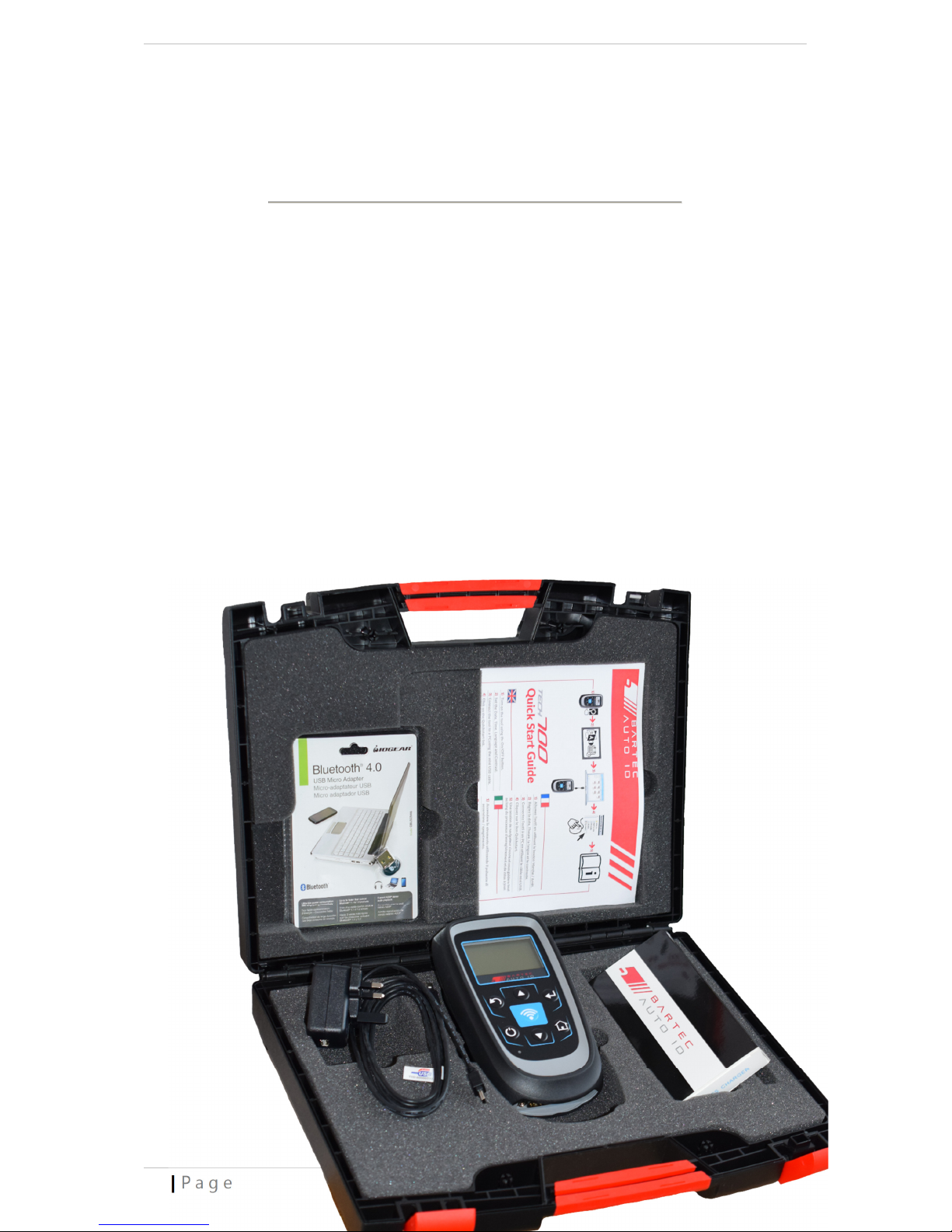
The TECH700 kit inside the tool box includes:
• Sensor diagnostic tool
• USB cable
• Wireless charger
• Quick Start Guide
• Bluetooth-Dongle
Identifying Kit Components and Features
The TECH700 is battery operated and generates a low-frequency magnetic field to
activate tyre sensors. It receives UHF radio signals from the tyre sensors typically at
433MHz and 315MHz
10 | P a g e
Page 11
T E C H 7 0 0 User Guide 2 0 1 8
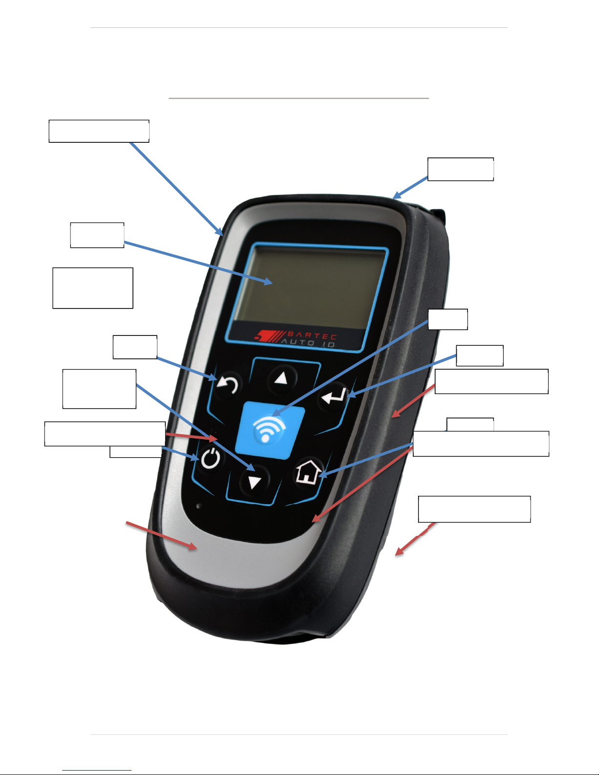
Test
Enter
Bluetooth
-
Dongle
T
OOL LAYOUT
Rubber housing
USB Cable
and Charger
Display
Back
Mini USB
Up/Down
navigation
On/Off
Quick-Start-Guide
Sensor diagnostic tool
Wireless-Charger
P a g e | 11
Page 12

T E C H 7 0 0 User Guide 2 0 1 8
M
ENU NAVIGATION
The TECH700 menu system provides a hierarchy of instructions and commands. The
top line of the display will always indicate the current menu selected. The home key
will always return to the Home Menu screen.
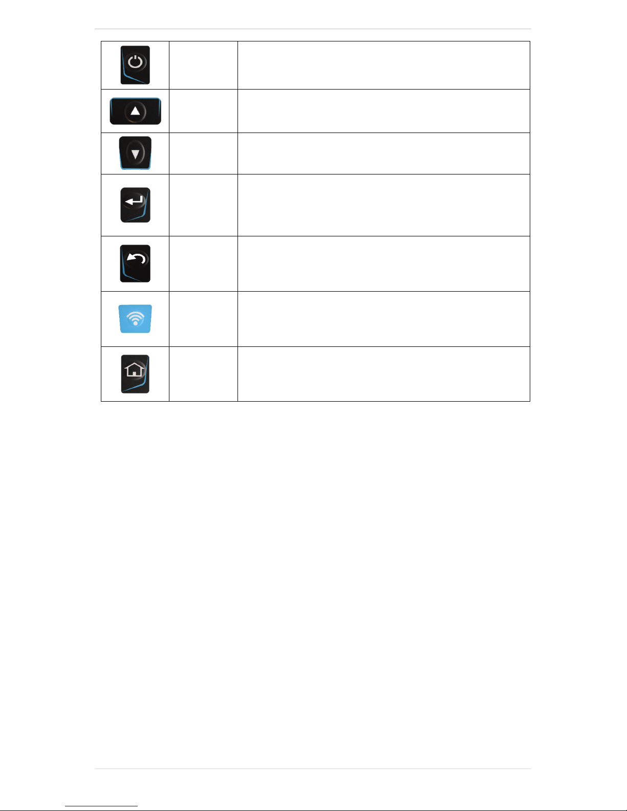
The menu system is navigated by the directional keys:
12 | P a g e
Page 13
T E C H 7 0 0 User Guide 2 0 1 8
Down Arrow
On/Off Key
Up Arrow
Key
Key
ENTER Key
Back/ESC
Key
TEST Key
Hold down for a few seconds to turn on or off
Navigates up within the current menu selection
Navigates down within the current menu selection
Navigates to the next menu or actions
the currently highlighted item
Navigates to the previous menu item
Initiates a TPMS test
Home Key
Using the up and down arrow keys, the display will wrap around.
Always returns to the Home Menu
P a g e | 13
Page 14
T E C H 7 0 0 User Guide 2 0 1 8
T
OOL POSITIONING
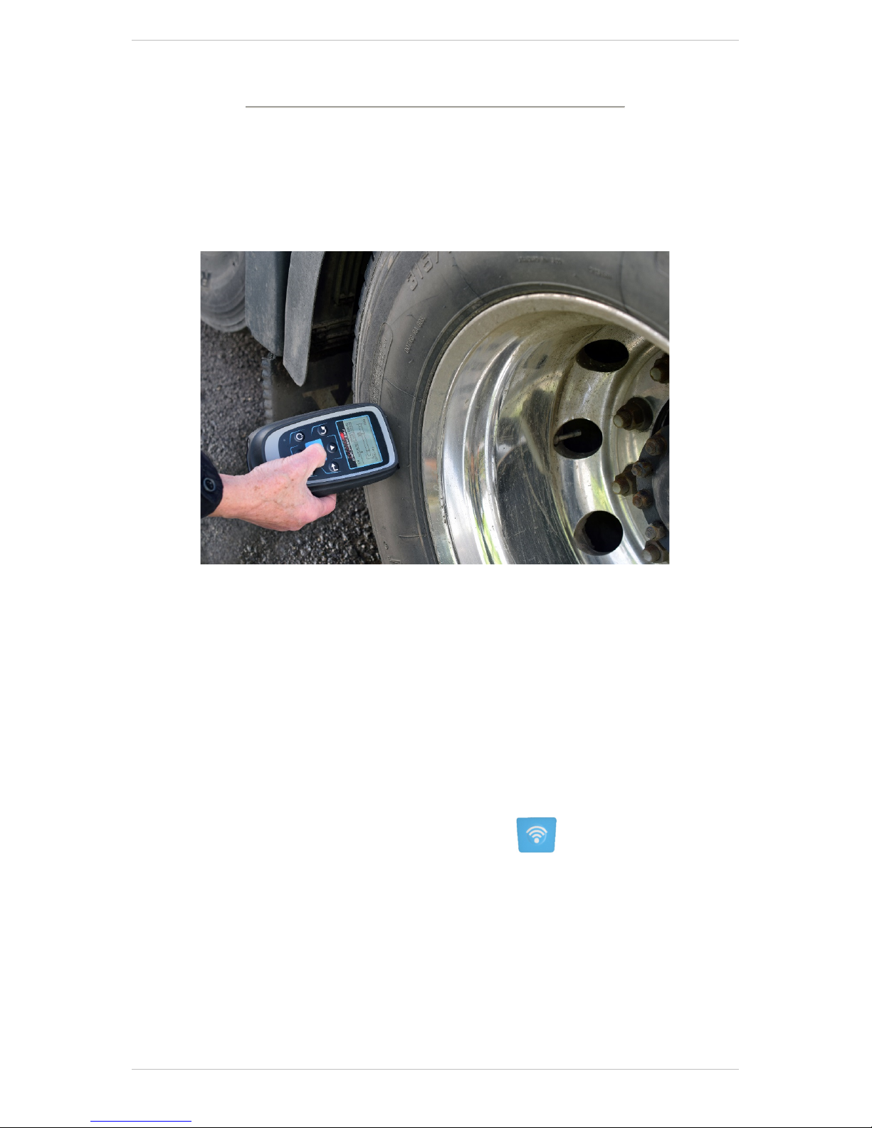
Correct tool positioning is important to ensure effective sensor activation and
decode. Place the TECH700 against the tyre wall, adjacent to the tyre valve stem,
pointing towards the sensor location as shown below. Avoid placing the tool over the
metal rim.
Wheels that are clamped together in a dual configuration have their sensors
positioned at 180 degrees to each other. The outer wheel should always be read first
as it is visually easier to find. To read the inner wheel sensor, it is important to place
the tool 180 degrees from the outer sensor. Also the top of the tool needs to be
placed between the two wheels pointing toward the inner sensor.
Sensor Activation
LF Activated Sensors
Once the tool is correctly aligned press the “Test” key.
Hold the tool in the same position until the progress bar has timed out.
Depending on the sensor type selected the response time could vary by several
seconds.
A successful read will be acknowledge with a beep tone and the tool will vibrate.
(Haptic response)
14 | P a g e
Page 15
T E C H 7 0 0 User Guide 2 0 1 8
T
OOL CONNECTIONS
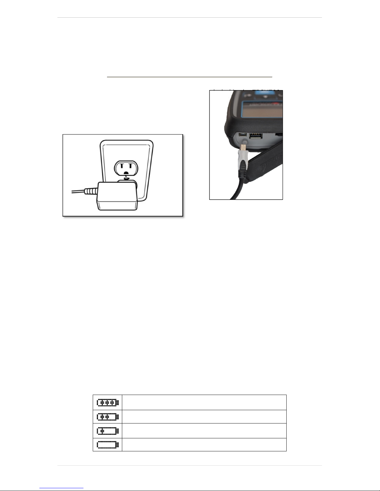
NOTE: Only use the power supply or USB cable included in the TECH700 kit to charge
this tool. The use of unapproved power supplies may damage your tool and will
invalidate the tool warranty.
/C
HARGING TOOL
The TECH700 comes with the rechargeable battery already installed. Battery
replacement must be done at the factory.
For optimum performance, always keep your TECH700 sufficiently charged. It is
recommended that you charge the tool at least two hours before first use.
The charging port is a mini USB port, located on the top side of the tool.
Battery Indicator
This status line Indicator will illustrate the remaining charge status of the battery.
Reading different TPM types will use up differing amounts of energy, and so the
indicator can only provide an estimate of remaining life left before a recharge is
required.
FULL Charge
Partial Charge - charging shortly is suggested.
Low power in the battery - charging required.
The battery is FLAT, requires charging
P a g e | 15
Page 16

T E C H 7 0 0 User Guide 2 0 1 8
During charging the battery status icon will scroll.
At the point of insufficient battery power the TECH700 will flash its battery icon for two
seconds. The TPM Data will be saved prior to power off.
P
OWER
The TECH700 is powered up using the ON/OFF key.
To power up the unit hold down the ON/OFF key for approximately 2 seconds.
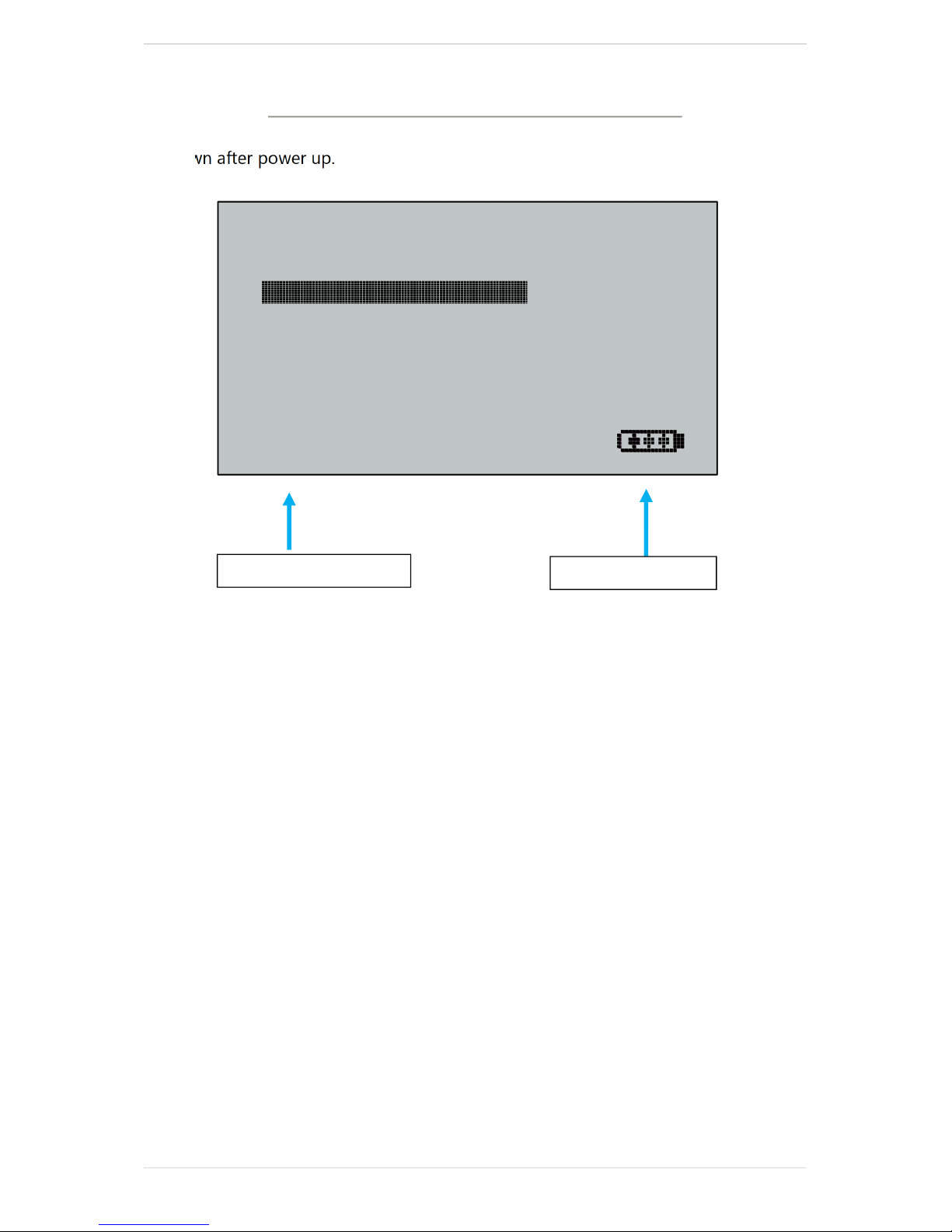
On power up, a screen will appear displaying the software version in use
ON/OFF S
EQUENCE
The main menu screen will then appear.
To power off the TECH700 use the same ON/OFF key.
Hold down the key until ‘Goodbye’ is displayed.
The tool automatically powers off after 5 minutes of inactivity.
All results and settings are stored during automatic or manual intervention.
The Tool automatically powers up when the charger or USB port is in use. Auto
power off is not operational.
16 | P a g e
Page 17
T E C H 7 0 0 User Guide 2 0 1 8
Battery indicator
Number of selections
H
OME MENU
The home screen, which provides access to the main functional items of the TECH700,
is shown after power up.
Home
Vehicle Check
Sensor Check
View Sensor Data
Delete Data
Toolkit
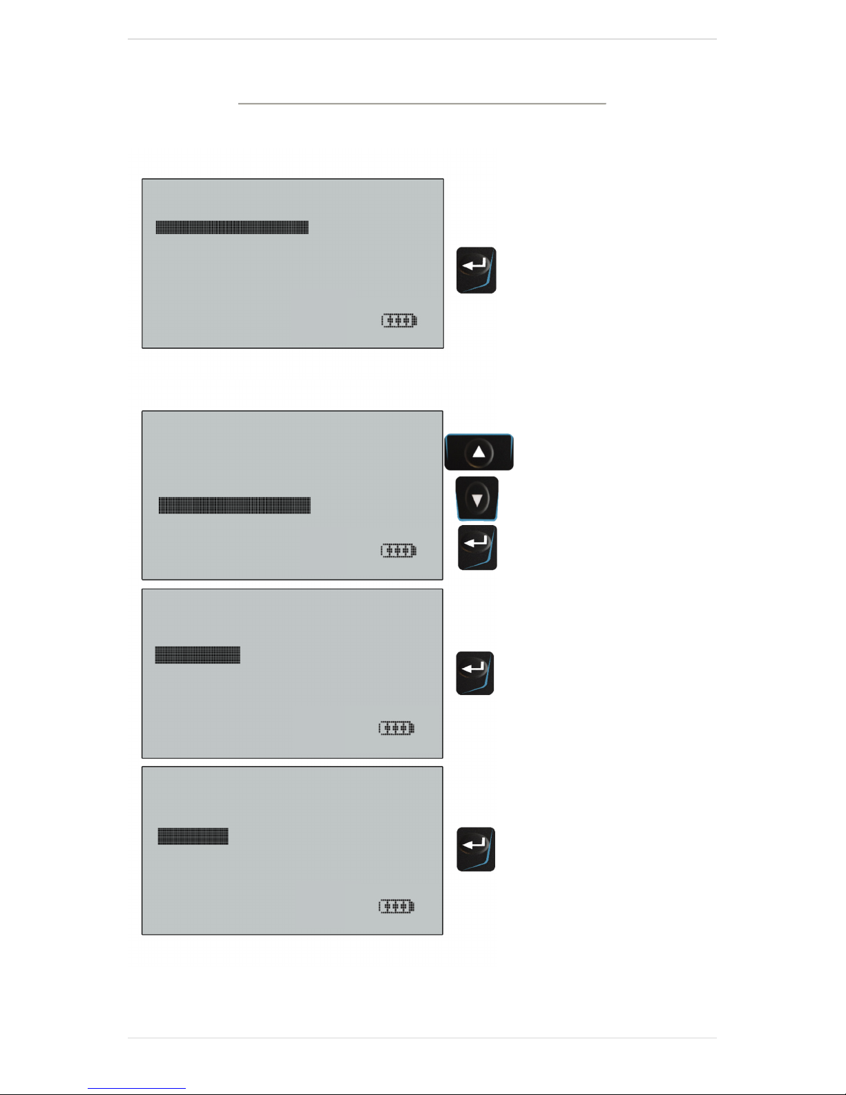
1. Vehicle Check
When highlighted, press the enter key to view the vehicle manufacturers e.g.
Mercedes, DAF and Setra etc.
2. Sensor Check
When highlighted, press the enter key to select by sensor type and capture all
relevant sensor data.
3. View Sensor Data
Wheels To Test:
When highlighted, press the enter key to view the data records.
4. Delete Sensor Data
When highlighted, press the enter key to delete the data records. A security screen
prompt will appear providing the option to escape or continue.
5. Toolkit
This feature provides facilities for RKE testing and UHF monitoring.
P a g e | 17
Page 18

T E C H 7 0 0 User Guide 2 0 1 8
6. My Tool
This feature provides access to
WiFi, Tool Info, Enter update Mode, Usage, support, and Workflow
Settings allowes changes to: Date/Time, Restore Defaults, Sensor ID, Pressure,
Temperature, Display Contrast and Language.
WiFi select “WiFi” to enable or disable the Wifi function and to join an existing
Network.
Tool info provides the reference to Software Version, Build Date, Serial Number,
Language Region and Coverage Region
Enter Update Mode provides a method of updating the software within the tool
Usage provides data on charging cycles and number of sensors activated
Support provides contact details for assistance
WorkFlow provides the possibility to change the format of registration plates
depending on the country they originate from
18 | P a g e
Page 19
T E C H 7 0 0 User Guide 2 0 1 8
VEHICLE CHECK
Vehicle Check
Sensor Check
View Sensor Data
Delete Data
Toolkit
My Tool
Select by Make
DAF
Ford
FUSO
Mercedes-Benz
Setra
Select by Model
Actros
Antos
Arocs
Mercedes-Benz Actros
2002-17
2017>
1/2
Home
P a g e | 19
Page 20
T E C H 7 0 0 User Guide 2 0 1 8
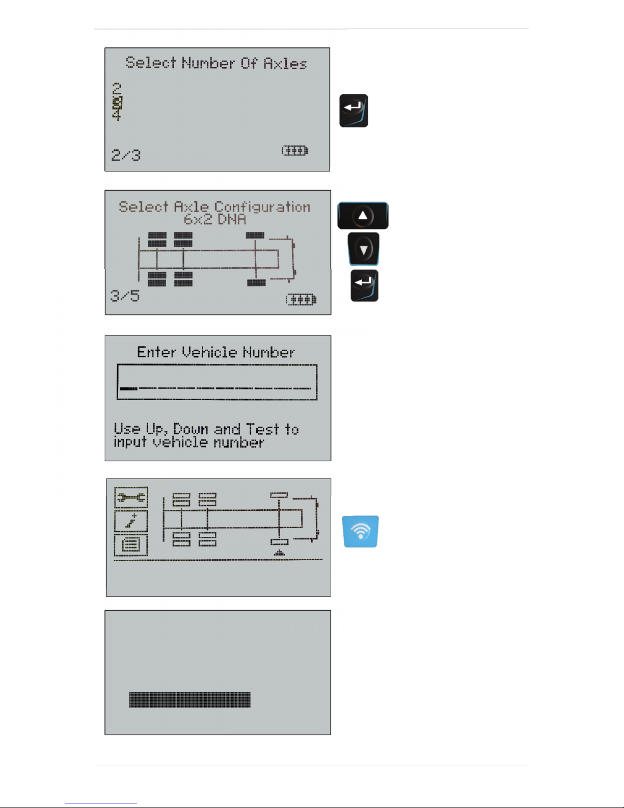
Press Test To Activate
Searching
Receiving Data:001
20 | P a g e
Page 21
T E C H 7 0 0 User Guide 2 0 1 8
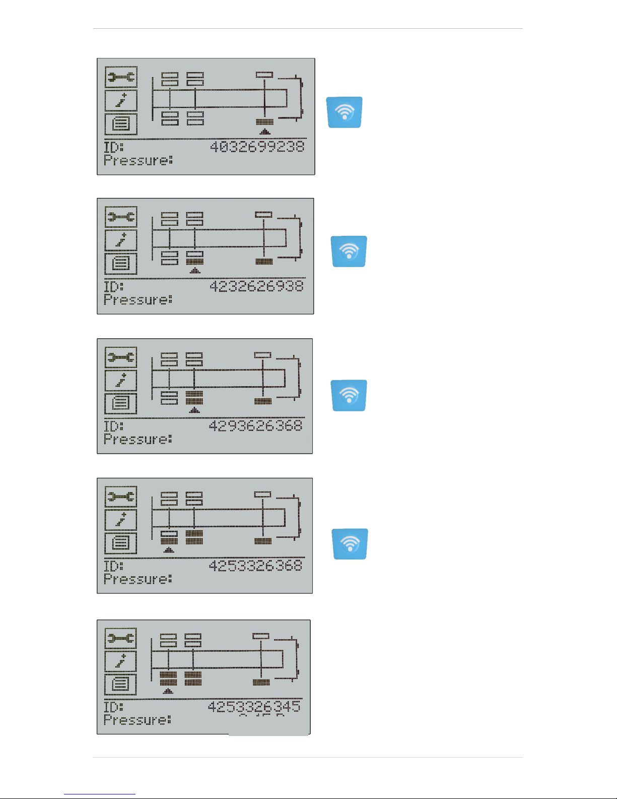
111
PSI
113
PSI
112
PSI
117
PSI
118
PSI
P a g e | 21
Page 22
T E C H 7 0 0 User Guide 2 0 1 8
SENSOR CHECK
Home
Vehicle Check
Sensor Check
View Sensor Data
Delete Data
Toolkit
My Tool
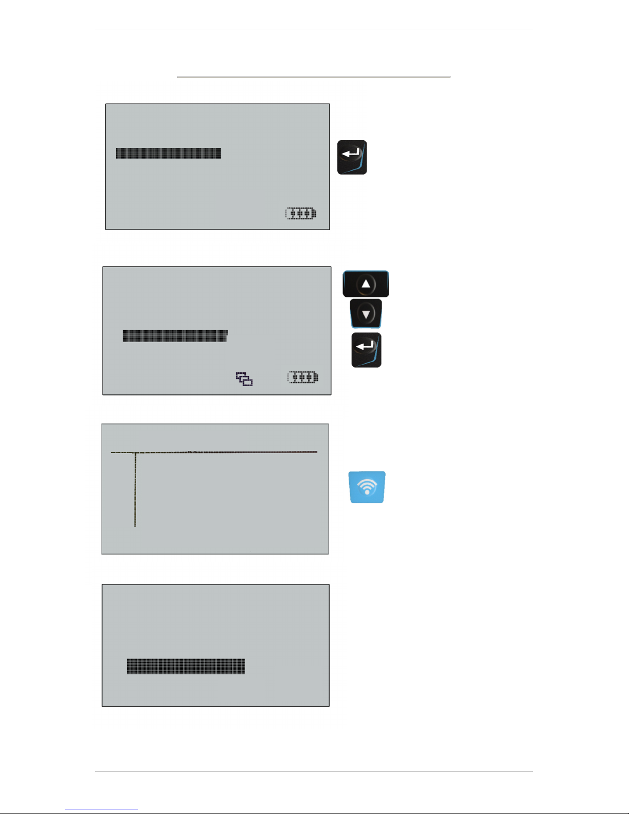
Select Sensor Type
Bendix
Huf
Huf Delta-P
Schrader PAL
Pos ID (Auto) PSI
1 Untested
2 Untested
3 Untested
4 Untested
Searching
Receiving Data:001
22 | P a g e
Page 23
T E C H 7 0 0 User Guide 2 0 1 8
113
56338C8E 118
Sensor Type
4
4
1446218894 26
Stationary
90%
4
4
Pos ID (Auto) PSI
1 F05E0B14
2 Untested
3 Untested
4 Untested
4 additional reading later:
56338FB3 116
1
56338F60 113
2
596836B7 112
3
1446219699 25
1
1446219616 25
2
1500001975 26
3
1
Stationary 90%
2
Stationary 90%
3
Stationary 100%
Schrader PAL(Merc.)
1
Schrader PAL(Merc.)
2
3
Schrader PAL(Daf.)
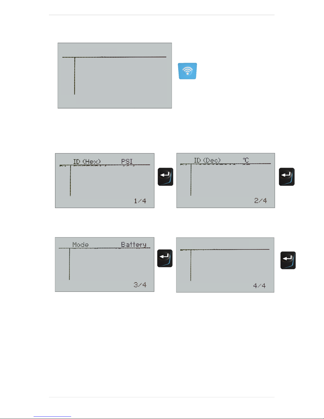
The sensor Type Screen provides additional information on the variant of Pal
Sensor.
P a g e | 23
Page 24
T E C H 7 0 0 User Guide 2 0 1 8
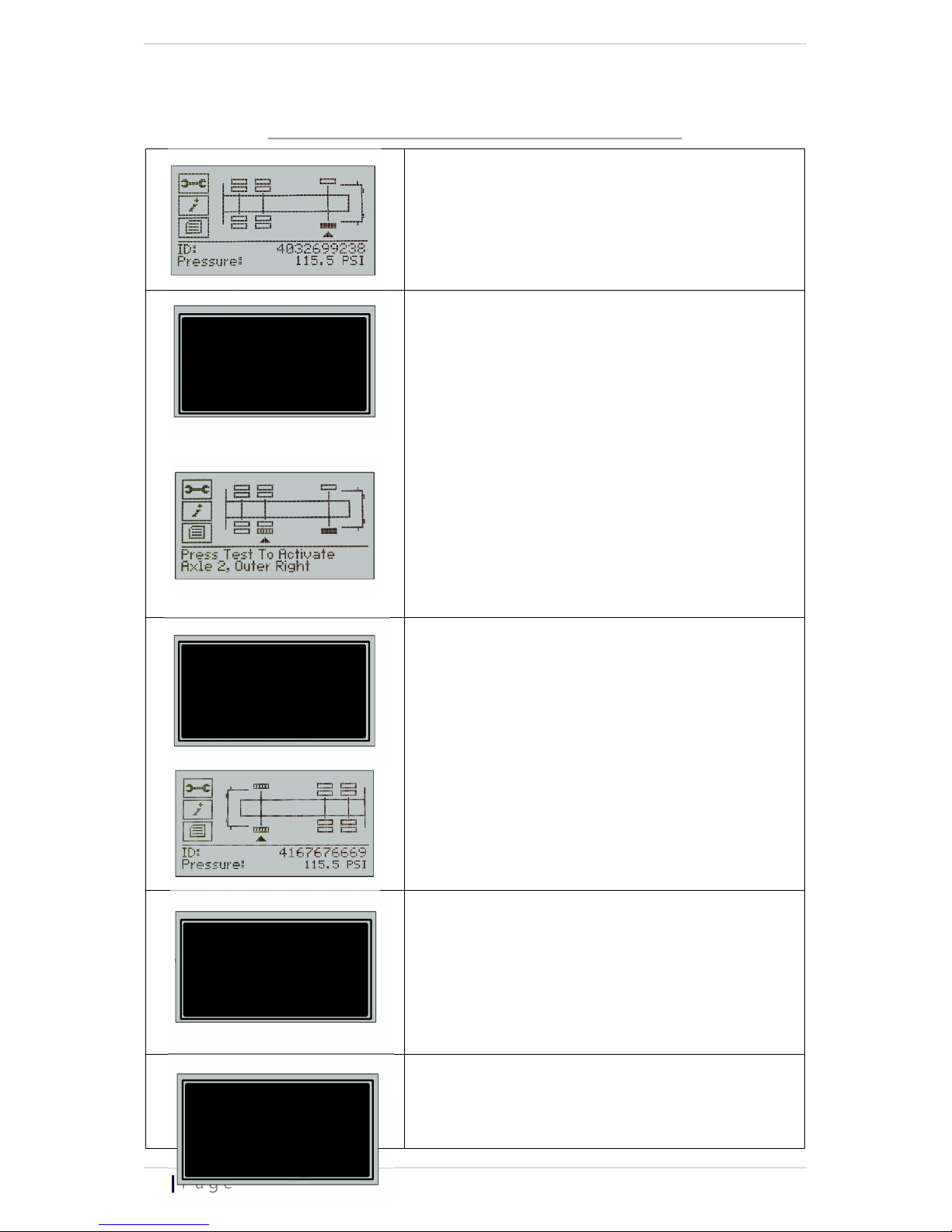
P
OSSIBLE READING SCENARIOS
Successful Sensor Read
TPMS sensor was successfully activated and
decoded. Displays pressure (in Bar, PSI or KPa) at
wheel location. The wheel icon will appear filled
in
No Sensor found
Press any key to continue
This may be due to a broken sensor, no sensor
No Sensor found
fitted or an incorrect type of sensor has been
fitted.
Duplicate Sensor
Please Re-read sernsors
Press any key to continue
Detected
Sensor Low Battery
detected
No Sensor found
Check part number
Duplicate ID
This indicates that a sensor that has already been
read has been read again and assigned to
another wheel position.
The wheel icon will appear with vertical stripes
Low Sensor Battery
This indicates that the internal battery of the
sensor under test is providing a low battery
warning.
Check part number
This indicates that the sensor found does not fit
to the pre-selected Make,Modell,Year.
24 | P a g e
Page 25
T E C H 7 0 0 User Guide 2 0 1 8
Sensor Type
V
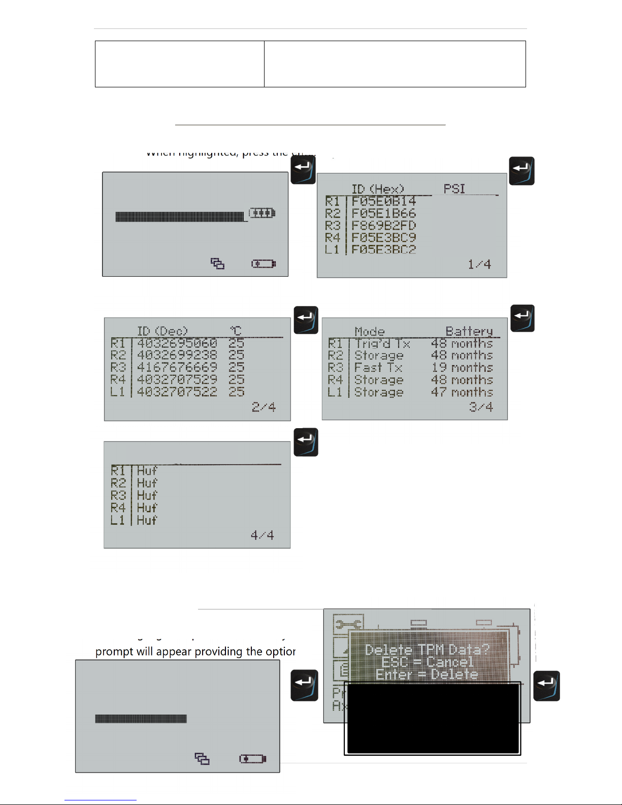
When highlighted, press the enter key to review the data records.
Homehicle
Vehicle Check
Sensor Check
View Sensor Data
Delete Data
Toolkit
Check the sensor Part number to insure the
correct fitment for the vehicle selected.
IEW SENSOR DATA
116.0
115.5
114.2
DELETE SENSOR DATA
When highlighted, press the enter key to delete the data records. A security screen
prompt will appear providing the option to escape or continue.
Vehicle Check
Sensor Check
View Sensor Data
Delete Data
Toolkit
My Tool
Homehicle
Delete sensor Data ?
Enter = Delete
ESC = Cancel
P a g e | 25
Page 26
T E C H 7 0 0 User Guide 2 0 1 8
S
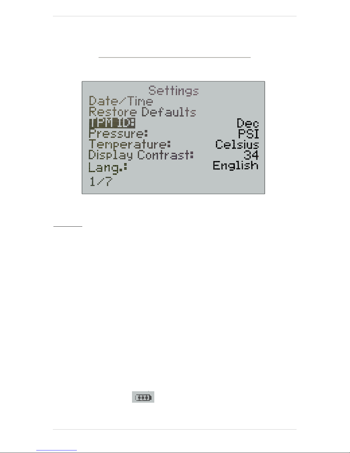
ETTINGS
When highlighted, press the enter key to change the settings.
Settings
Sensor ID:
Select to display the Sensor ID in DECIMAL, HEXIDECIMAL or AUTO. Automatic
reading matches the ID format to the sensor under test.
Pressure:
Select to display the required units of measurement: PSI, Bar and KPa.
Temperature:
Select to display the required units of measurement: Fahrenheit or Celsius.
Display Contrast:
Select to adjust the display contrast as required.
Lang.:
Select to display the required user language.
Languages supported: English, French, German, Italian, Turkish, Portuguese, Czech,
Dutch, Swedish, Spanish, Polish, Danish, Hungarian, Slovakian.
If a language is selected by mistake, press the home button followed by depressing
the back key for approx. 5 seconds. The display will then prompt the operator to
restore defaults that returns to English.
Date and Time: Select to Set the current Date and Time.
26 | P a g e
Page 27
T E C H 7 0 0 User Guide 2 0 1 8
Current
Restore Defaults: Select to reset the device to the factory settings.
R
ESULTS AUDIT SYSTEM
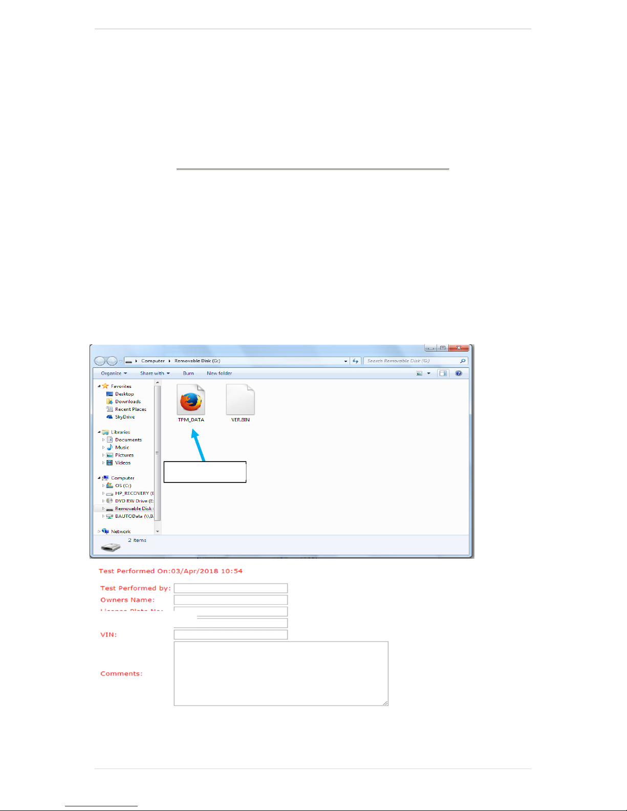
The TECH700 provides stored data record as an audit file via USB to a PC. The
TECH700 appears as a “Mass Storage Device”. No additional software is required. The
USB cable is included in the toolkit.
It is not necessary to power up the tool prior to connecting to the PC – the tool will
power up automatically.
Audit File Presentation
The Data is presented in HTML format that displays additional information relating to
the type of sensors tested.
Exit Audit Mode
To exit Audit mode simply remove the USB lead.
Tech 700 v57.0.3.2 TR
P a g e | 27
Page 28
T E C H 7 0 0 User Guide 2 0 1 8
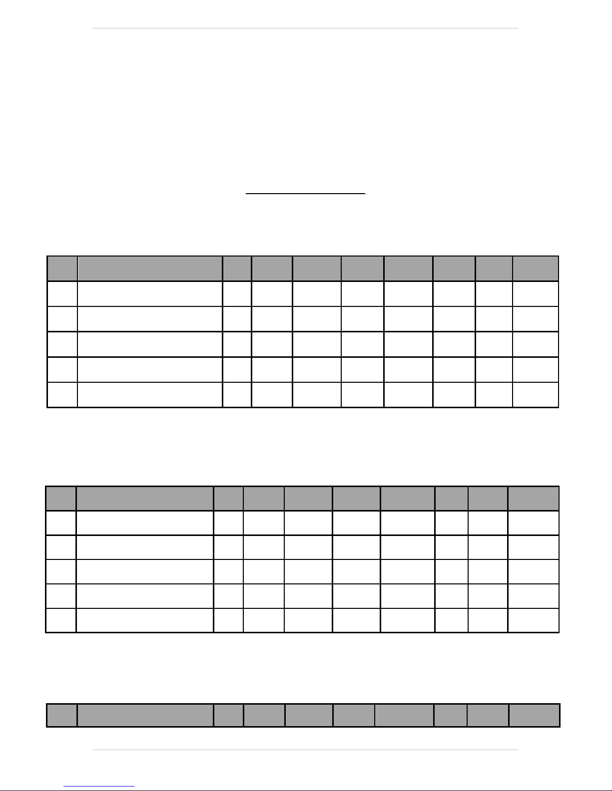
Audit file examples
Mercedes:
Wheel TPM Type Reads ID Hex ID Dec Mode
R1 BERU GEN3.42 19200 Bi-Phase 433 MHzFM 1 F869B2FD 4167676669 Trig´d Tx OK
R2 BERU GEN3.42 19200 Bi-Phase 433 MHzFM 1 F05E3BC2 4032707522 Trig´d Tx OK
R3 BERU GEN3.42 19200 Bi-Phase 433 MHzFM 1 F05E0B14 4032695060 Trig´d Tx OK
R4 BERU GEN3.42 19200 Bi-Phase 433 MHzFM 1 F05E1B66 4032699238 Trig´d Tx OK
R5 BERU GEN3.42 19200 Bi-Phase 433 MHzFM 1 F05E346E 4032705646 Trig´d Tx OK
DAF:
Battery
State Battery Pressure
19
Months 113 PSI
47
Months 114 PSI
47
Months 118 PSI
48
Months 115 PSI
48
Months 112 PSI
Temperature
23°C
23°C
23°C
23°C
23°C
Wheel TPM Type Reads ID Hex ID Dec Mode Battery State Battery Pressure Temperature
R1 Schrader 9600 Manchester 433 MHzFM 1 56338F4A 1446219592 Stationary OK 90% 113 PSI 23°C
R2 Schrader 9600 Manchester 433 MHzFM 1 56338F4A 1446219699 Stationary OK 90% 118 PSI 23°C
R3 Schrader 9600 Manchester 433 MHzFM 1 5968371C 1500002076 Stationary OK 100% 114 PSI 24°C
R4 Schrader 9600 Manchester 433 MHzFM 1 596833F6 1500001570 Stationary OK 100% 112 PSI 23°C
R5 Schrader 9600 Manchester 433 MHzFM 1 596836B7 1500001975 Stationary OK 100% 114 PSI 25°C
SETRA:
Wheel TPM Type Reads ID Hex ID Dec Mode Battery State Battery Pressure Temperature
28 | P a g e
Page 29

T E C H 7 0 0 User Guide 2 0 1 8
R1 Schrader 9600 Manchester 433 MHzFM 1 563053AB 1446007723 Stationary OK 90% 114 PSI 22°C
R2 Schrader 9600 Manchester 433 MHzFM 1 5631350 1446065633 Stationary OK 80% 112 PSI 22°C
R3 Schrader 9600 Manchester 433 MHzFM 1 56305354 1446007636 Stationary OK 90% 118 PSI 22°C
R4 Schrader 9600 Manchester 433 MHzFM 1 56305391 1446007697 Stationary OK 90% 118 PSI 23°C
R5 Schrader 9600 Manchester 433 MHzFM 1 56305372 1446007666 Stationary OK 90% 113 PSI 23°C
T
ECHNICAL SPECIFICATION
TECH700 TECHNICAL SPECIFICATION
Power Supply: Lithium Polymer rechargeable battery, not user serviceable...
Max power consumption: 1.5W Schrader TPM, 0.5W all others
Display: LCD display. Resolution 128x64 pixels
Keyboard: 7 keys membrane keyboard
Input/output: Mini-B style USB used to Connect to PC for firmware update and
audit file download.
Working environment: Temperature 0°C - 45°C, Humidity: 20-55%
Storage environment: Temperature - 10°C - 50°C, Humidity: 20-60%
Dimensions: 187mm x 107mm x 47mm
Weight (including batteries): 410g
P a g e | 29
 Loading...