


Tech 500 User Guide rev1.0 JUNE 2013
1
TABLE OF CONTENTS
IMPORTANT NOTICES 2
BEFORE YOU GET STARTED 3
TOOL LAYOUT 4
TOOL CONNECTIONS 5
POWER ON/OFF 6
CHARGING TOOL 7
TOOL DISPLAY AND ICONS 8
MENU SYSTEM
TEST BEFORE YOU TOUCH
RELEARN
REVIEW DATA
TOOLKIT
MY TOOL 11
TOOL POSITIONING/READING A SENSOR 20
UPDATING YOUR TOOL (PC) 29
UPDATING YOUR TOOL (SD Card) 32
UPDATING YOUR TOOL (Wireless)
APPENDIX A: INDUCTIVE CHARGING
APPENDIX B: VIN 37
APPENDIX C: FAQ’S & TROUBLESHOOTING GUIDE 38
APPENDIX D: DEFINITIONS 39
APPENDIX E: TPMS SYSTEM REVIEW 40
APPENDIX F: COMS ERROR TROUBLESHOOTING 42
APPENDIX G: Technical Support 43
LIMITED WARRANTY 44
TOOL REGISTRATION 47

Tech 500 User Guide rev1.0 JUNE 2013
2
INCLUDED IN Tech500 KIT:
Tech500 TPMS Tool [with protective Boot]
SD Card [in the tool]
Power Supply
Re-Learn Magnet
USB Cable
DB15 to OBDII Cable
Tech500 Quick Start Guide
Tech500 User Guide
Kit CD
IMPORTANT NOTICES
All specifications, illustrations and information contained within this manual are based on the
most current information available at the time of publication. BartecUSA reserves the right to
make changes at any time without obligation to notify any person or organization. BartecUSA
will do its best to keep you the customer informed of any changes that might affect the tools
performance.
FCC Compliance Model: DSW
FCC ID: SX8T500 IC: 5736A-T500
Contains FCC ID: QOQWT12 IC: 5123A-BGTWT12A
Contains FCCID: YOPGS1011MIP IC: 9154A-GS1011MIP
This device complies with Part 15 of the FCC Rules and with Industry Canada
license-exempt RSS standard(s). Operation is subject to the following two
conditions: (1) This device may not cause harmful interference, and (2)
This device must accept any interference received, including
interference that may cause undesired operation.
Le présent appareil est conforme aux CNR d'Industrie Canada applicables aux
appareils radio exempts de licence. L'exploitation est autorisée aux deux
conditions suivantes : (1) l'appareil ne doit pas produire de brouillage, et (2)

Tech 500 User Guide rev1.0 JUNE 2013
3
l'utilisateur de l'appareil doit accepter tout brouillage radioélectrique subi,
même si le brouillage est susceptible d'en compromettre le fonctionnement.
Note: Changes or modifications not expressively approved by the party
responsible for compliance could void the user's authority to operate the
equipment.
Note: This equipment has been tested and found to comply with the limits for
a Class A digital device, pursuant to Part 15 of the FCC Rules. These limits are
designed to provide reasonable protection against harmful interference when
the equipment is operated in a commercial environment. This equipment
generates, uses, and can radiate radio frequency energy and, if not installed
and used in accordance with the instruction manual, may cause harmful
interference to radio communications. Operation of this equipment in a
residential area is likely to cause harmful interference in which case the user
will be required to correct the interference at their expense.
BEFORE YOU GET STARTED
Before you get started using your Tech500 TPMS tool, there are a few items to review.
Charge your tool
The Tech500 is shipped with a fully charged battery, but due to shelf drain it may require
charging. It is recommended to charge your tool 2+ hours before use. (See page 6 for charging
instructions)
Register your tool
You can register your Bartec
Tech500 @ www.bartecusa.com.
Follow the on-screen prompts filling
in your information and tool serial
Tech 500 User Guide rev1.0 JUNE 2013
4
number. A valid serial number and supplier is required to process your registration, which can
take up to 24hrs once submitted.
Update your Tool
Once your tool is registered, verify the software level loaded to the level available online and
update your tool if necessary. Refer to section on tool updating for further instruction.
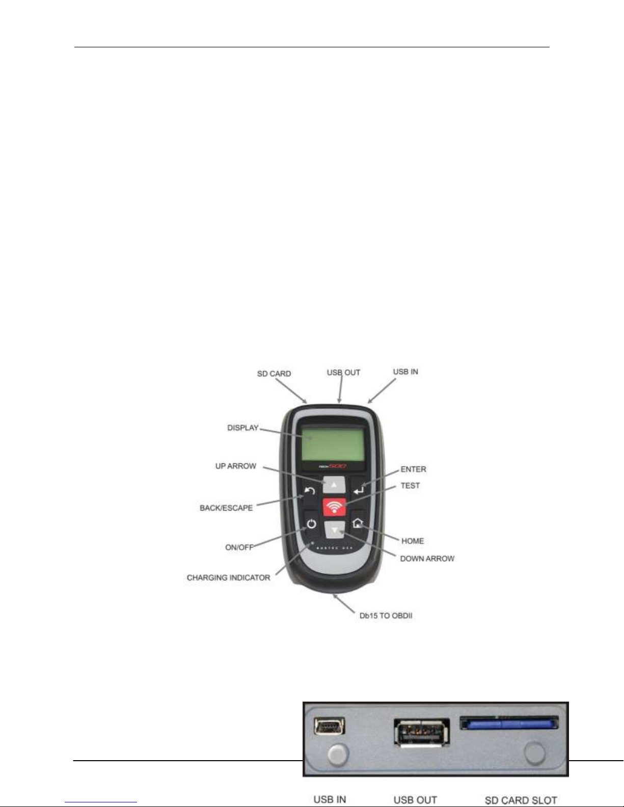
TOOL LAYOUT
TOOL CONNECTIONS

Tech 500 User Guide rev1.0 JUNE 2013
5
POWER ON/OFF SEQUENCE
The Tech500 is powered up using the ON/OFF key.
On/Off Key
To power the unit on press the On/Off Key for approx 2 seconds – the display will light showing
a logo and software version.
The unit will then display the Main Menu. All data (results and settings) from previous tests is
reloaded.

Tech 500 User Guide rev1.0 JUNE 2013
6
Power down the Tech500 by using the same ON/ OFF key.
On/Off Key
(Hold, then release when ‘Goodbye’ is displayed.) Auto power off is after 5 minutes of
inactivity.
The unit automatically powers up when the charger or USB port is in use- auto power off is not
operational.
CHARGING TOOL
NOTICE: Only use the power supply or USB cable that is included in the Tech500 tool kit to
charge this tool. The use of un-approved power supplies may damage your tool and will void
the tool warranty.

Tech 500 User Guide rev1.0 JUNE 2013
7
# of selections
USB indicator
Data stored on tool
Battery indicator
The Tech500 comes with the rechargeable battery already installed. Battery replacement must
be done at the factory.
For optimum performance, always keep your Tech500 sufficiently charged. It is recommended
that you charge the tool 2 + hours before first use.
The charge port is located on the right side of the tool and is the USB port opening.
TOOL DISPLAY AND ICONS
# of selections

Tech 500 User Guide rev1.0 JUNE 2013
8
FULL Charge
Partial Charge - charging shortly is
suggested.
The menu page number (e.g. x/y) on the status line indicates the menu page or item currently
displayed. The first number- x- indicates the item number selected. The second- y- indicates the
total number of items available.
USB Indicator
This status line indicator confirms the Tech500 is connected to the USB port of a computer.
Once communication has been established, results data can be viewed on the pc via the Mass
Storage Device feature. (Use the PC explorer program) “HTM File”
When the USB lead is removed the USB icon will disappear.
Battery Indicator/ Charging
This status line Indicator will illustrate the remaining charge status of the battery.
As different TPM types will ‘use up’ differing amounts of energy, the indicator can only provide
estimates of remaining life left before a recharge is required.

Tech 500 User Guide rev1.0 JUNE 2013
9
Little power in the battery- charging
required.
The battery is FLAT, requires
charging
When the battery is being charged the indicator segments ‘walk;’ from left to right.
When there is an insufficient amount of power remaining in the battery, the Tech500 will flash
its battery icon for two seconds, save all of the TPM Data and then power itself off.
Results Data Available Indicator
Indicates TPM data is available for viewing on the screen (using the View TPM Data command
from the main menu) or via a PC when the Tech500 is in its Mass Storage Device mode. (See
Section on Audit Mode)

Tech 500 User Guide rev1.0 JUNE 2013
10
Current report
Archived reports
When there is no data present, the TPM Data Indicator will not be visible.
To Access the Audit Data, connect your tool to the PC using the supplied USB Cable.
MENU SYSTEM
The Tech500’s menu system provides a hierarchy of instructions and commands. The top line of
the display will always indicate the current menu selected. The home key will always return to
the Main Menu screen- with ‘Select by Vehicle’ highlighted.

Tech 500 User Guide rev1.0 JUNE 2013
11
Up Arrow Key
Navigates up within the current menu
Down Arrow
Key
Navigates down within the current
menu
ENTER Key
Navigates to the next menu or actions
the currently selected item
Back/ESC Key
Navigates to the previous menu item
TEST Key
Commence a TPM test. Only works on
Audit Screen
Home Key
Always returns to the Home Menu
Menu Navigation
The menu system is navigated by the directional keys:
All menus wrap around. The enter key will primarily move to a sub menu.
Home Menu
This is the main screen- providing access to the main functional items of the Tech500.

Tech 500 User Guide rev1.0 JUNE 2013
12
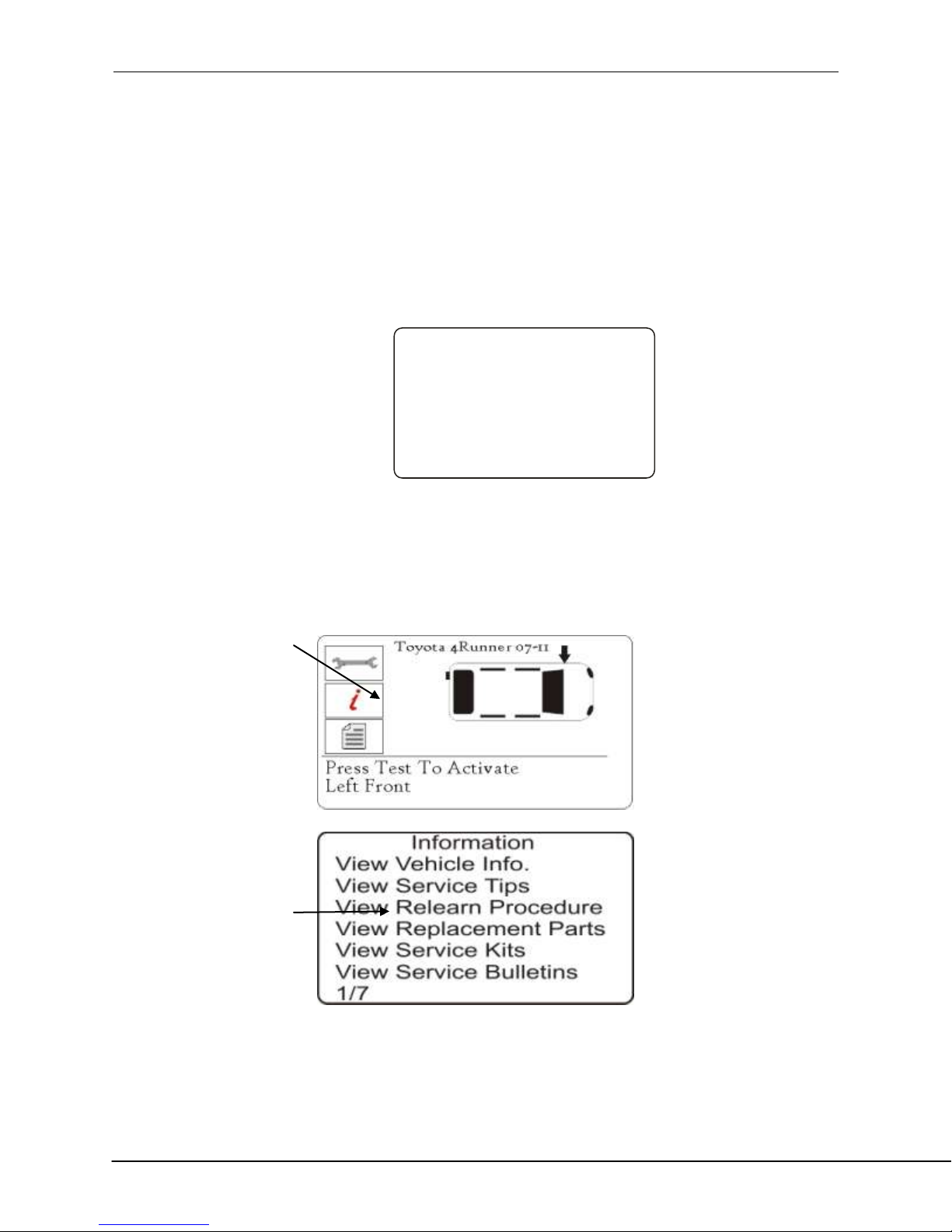
TBYT/Relearn Toolkit
View Vehicle Info
Review Vehicle Data
1. Test Before You Touch
This Item is a sub menu, pressing the Enter Key will take the user to the “Test Before
You Touch” menu. The user should select the vehicle make, model and year. Used when
doing a pre-service scan.
2. Relearn
This Item is a sub menu, pressing the Enter Key will take the user to the “Test Before
You Touch” menu. The user should select the vehicle make, model and year. Used when
relearning the sensor ID’s to the vehicle.
3. Review Data
This item is a sub menu, pressing the Enter Key will take the user to the results screens.
Press directional arrows to examine the required results.
4. Toolkit
A sub-menu in which you will find your options for EZ sensor, RKE monitor, and UHF
monitor.
5. My Tool
Sub-menu containing important info about the tool itself.
Operations Screen
This screen is where you will complete all sensor testing and relearn steps.

Tech 500 User Guide rev1.0 JUNE 2013
13
Possible Scenarios
Successful Sensor Read
TPMS sensor was successfully activated and decoded. Displays pressure at wheel location.
Wrong Sensor Type
A TPMS sensor was activated and decoded, but does not match the protocol for the Make
Model Year that the tool was set-up for.
Failed Sensor Read
No Sensor Activation or Decode. May be wrong sensor fitment or non-functioning sensor. Tool
will prompt you to attempt reading the sensor 3 times.
Duplicate ID
A sensor with a duplicate ID has been read. The tool will direct you to re-read those sensors.
No Pressure
Sensor IDS read from ECU.
Low Battery

Tech 500 User Guide rev1.0 JUNE 2013
14
Select by Make
Buick
Cadillac
Chevrolet
Chrysler
Dodge
7/45
Chevrolet
Corvette
Corvette C5
Corvette C6
Corvette Z06
Cruze
9/29
Chevrolet Cruze
2011
2012
1/2
ID:8920758D TEMP: 85
Mode: Learn BAT: Norm
32
32
32
32
Diagnosis:
Sensor Failure Detected
View data or print audit
report for details
Press any key to continue
Home
Test Before You Touch
Relearn
Review Data
Toolkit
My Tool
1/5
Sensor’s internal battery has dropped below a certain voltage threshold.
TEST BEFORE YOU TOUCH
TPMS is a process. With that Bartec has integrated that process to the tool. The 1st step with
TPMS is to conduct a Test Before You Touch. (Note: operator can skip TBYT and go directly to
RELEARN although not recommended). Test Before You Touch will prompt you through getting
a status of the vehicle prior to service by verifying the sensors are working and when
supported, verify the Diagnostic Trouble Codes (DTC).
To verify year, use 10th digit of the VIN.
Vehicle Operations Screen

Tech 500 User Guide rev1.0 JUNE 2013
15
If equipped, tool will prompt user to connect to OBD and retrieve Diagnostic Trouble Codes
The Tech500 has the ability to Read out vehicle DTCs (Diagnostic Trouble Codes). Once read,
you will need to reference these codes with an external reference to determine the codes
definition.

Tech 500 User Guide rev1.0 JUNE 2013
16
Home
Test Before You Touch
Relearn
Review Data
Toolkit
My Tool
1/5
Select by Make
Buick
Cadillac
Chevrolet
Chrysler
Dodge
7/45
Chevrolet
Corvette
Corvette C5
Corvette C6
Corvette Z06
Cruze
9/29
Chevrolet Cruze
2011
2012
1/2
RELEARN
Stationary Relearns
Active (Drive) Relearns
OBD Relearns
Stationary Relearns:
Stationary Relearns use the vehicles on-board TPMS system to listen for transmissions from
TPM sensors while the vehicle is in a “Learn Mode”. This is usually achieved through a series of
functions on the vehicle to place the vehicle into this mode.
Once the vehicle is in Learn Mode, using your Tech500 to activate the sensors, the vehicle will
listen for the sensor IDS and learn them to the vehicle.
Using your Tech500 to perform Stationary Relearns:

Tech 500 User Guide rev1.0 JUNE 2013
17
>Inflate tires to Placard
>Capture all 4 I D’s
>Turn ignition to ON
>Plug OBDII Cable and select
>Write ID’s to Vehicle
>Leave vehicle in the ON position
>Start vehicle and ensure light is off
ID:8920758D TEMP: 85
Mode: Learn BAT: Norm
32
32
32
32
Active (Drive) Relearns:
Active or Drive Relearns
Some vehicles can be reset by driving. Refer to the on-screen re-learn procedures for details on
how far/long to drive.
To verify year, use 10th digit of the VIN.
Follow on-screen instructions
Vehicle Operations Screen

Tech 500 User Guide rev1.0 JUNE 2013
18
Home
Test Before You Touch
Relearn
Review Data
Toolkit
My Tool
1/5
Select by Make
Buick
Cadillac
Chevrolet
Chrysler
Dodge
7/45
Chevrolet
Corvette
Corvette C5
Corvette C6
Corvette Z06
Cruze
9/29
Chevrolet Cruze
2011
2012
1/2
ID:8920758D TEMP: 85
Mode: Learn BAT: Norm
32
32
32
32
OBD Relearns:
Connection to a vehicle allows the Tech500 to directly program the vehicle electronics module
with TPM ID’s.
Note that not all vehicles support vehicle communications modes.
Once 4 TPM ID’s are stored within the Tech500, it can be connected to the OBD interface using
the provided cable.
Vehicle Operations Screen

Tech 500 User Guide rev1.0 JUNE 2013
19
Home
Test Before You Touch
Relearn
Review Data
Toolkit
My Tool
1/5
Select by Make
Buick
Cadillac
Chevrolet
Chrysler
Dodge
7/45
Chevrolet
Corvette
Corvette C5
Corvette C6
Corvette Z06
Cruze
9/29
Chevrolet Cruze
2011
2012
1/2
Connect tool to OBD II Port
and Turn Ignition ON
Press Enter to Read
Vehicle TPMS related info.
Press ESC to Cancel
During vehicle communication, the BACK key is inhibited. Should the process be commenced
inadvertently, the tool can be left to timeout on its own accord - approximately 20 seconds.
Once the communication is complete, the tool will flash IDS Written Successfully.
IF an Error Message comes up during the COMS process, Refer to Appendix F for COMS error
trouble shooting.
Indirect system – Vehicle may require calibration at point of service or replacement. No wheel
sensors on this type of TPMS.
Follow on-screen instructions
Tech 500 User Guide rev1.0 JUNE 2013
20
>Inflate tires to Placard
>Capture all 4 ID’s
>Turn ignition to ON
>Plug OBDII Cable and select
>Write ID’s to Vehicle
>Leave vehicle in the ON position
>Start vehicle and ensure light is off
To verify year, use 10th digit of the VIN.
Follow on-screen instructions
Viewing Full Relearn Procedures

Tech 500 User Guide rev1.0 JUNE 2013
21
REVIEW DATA:
This menu- when selected- gives direct access to specific screens that display the TPM data. No
menu page name is provided- instead, the screen provides all of the TPM Data available from
the TPM Type read; this may include: TPM ID (Hexadecimal & Decimal) Battery State,
Temperature and Pressure.
Not all TPM’s provide the same data.

Tech 500 User Guide rev1.0 JUNE 2013
22
TOOLKIT
Program Sensor
Access to program Aftermarket sensors. For more information, please log into the
tools.bartecusa.com account.
RKE Test
Once the Screen appears as below, hold the Key Fob as shown, and press the function buttons
on the FOB. The Tech500 will check only for a signal present. Verifying the Key Fob is
transmitting is important when performing relearn processes that use the Key Fob.

Tech 500 User Guide rev1.0 JUNE 2013
23
UHF Monitor
Allows operator to search for sensor signals. This feature is used for advanced diagnostics to
determine if our signals may be causing issues during sensor activation and vehicle relearns.
MY TOOL
Settings
TPM ID:
Select whether the tool displays the TPM ID in DECIMAL or HEXIDECIMAL
Pressure:
Change how pressure is displayed on the tool screen. Choose between PSI or Bar.

Tech 500 User Guide rev1.0 JUNE 2013
24
Temperature:
Select units between Celsius or Fahrenheit.
Display Contrast:
Adjust tool display contrast.
Lang.:
Select Language for tool. Select English, Spanish or French.
Profile:
Allows user to select the profile. For more information, visit the tools.bartecusa.com
site.
.
Tool Info
Gives the operator the ability to reference:
- Software Version currently loaded
- Build Date of that Software
- Serial Number
New Features
Selecting New Features will allow you to reference the features and additions for the software
release currently loaded to your tool.
Update Tool

Tech 500 User Guide rev1.0 JUNE 2013
25
Puts tool into “Update Mode”. For more details and the update process refer to UPDATE TOOL
section of User Guide.
Usage
Gives the operator the ability to track the number of:
- Power Cycles
- Sensor Activations
- OBD Relearns
Support
On screen reference for Bartec USA Technical Support:
Toll Free Phone: (866) 407-8767
Email: mrose@bartecusa.com
TOOL POSITIONING/READING A SENSOR

Tech 500 User Guide rev1.0 JUNE 2013
26
Proper tool positioning is important to insure sensor activation and decode. Place the Tech500
on the tire, at the TPMS sensor, pointed toward the sensor location as shown above.
Sensor Activation/ Test
LF Activated Sensors
To test a sensor the tool should be placed alongside the valve stem
and the ‘Test’ key pressed.
(Note with Ford Banded sensor’s, the tool should be held
180°away from the stem.)
Magnet Activated Sensors
If the TPM requires a magnet, place the magnet over the
stem and then place the tool alongside the stem- while
pressing the test key.
Delta P activated sensors
If the sensor requires tire deflation (of the order of 10PSI), then deflate the tire and place the
tool alongside the stem while pressing the test key.

Tech 500 User Guide rev1.0 JUNE 2013
27
During testing, the screen confirms the sensor type being tested and displays a progress bar.
The progress bar shows the maximum possible time for a successful read- different makes of
TPM respond at different speeds/ time intervals.
Sensor activation can be aborted at any time by pressing the BACK key. When the activation is
aborted, the user will be returned to the previous menu.
Sensor Found Response
If there is a successful TPM Read, then the Tech500 will show the air pressure stored in that
wheel.
Incorrect Sensor Found

Tech 500 User Guide rev1.0 JUNE 2013
28
A TPM sensor that uses the same LF activation as the correct sensor for the Make, Model, and
Year selected has been found. Since there are many TPM sensors that look alike, it can be easy
to fit the wrong sensor, or have been supplied the wrong sensor.
If you get a ? during testing, verify the MMY you have selected as well as the sensor part
number that was fitted.
Sensor Not Found Response
If the search period expires without reading a TPM then the Tech500 will emit a single Audible
Beep and indicate on the display that no TPM was found.
The TPM Data will still be stored but will indicate that the
TPM Failed to Read if the sensor fails 3 times.

Tech 500 User Guide rev1.0 JUNE 2013
29
UPDATING YOUR TOOL (PC)
The tool is compatible with PCs running Windows operating systems (version XP or 2000).
USB ports can be either version 1 or 2.
Step 1:
Plug your USB cable to the computer ONLY. Make sure computer is on and you have no
programs running. Power the Tech500 on, and from the Main Menu, Select “My Tool”, then
select “Update Tool”.
Tool will prompt user to “Insert USB Lead to Transfer Update Files”. Insert the USB cable to the
Tech500.
Step 2:
Your tool should open a window on your computer screen. The tool now is seen by your
computer as a Removable Disk.

Tech 500 User Guide rev1.0 JUNE 2013
30
Step 3:
Copy and paste – Drag and Drop the Update file (*.MFU) provided to you into the Removable
Disk Window. Once Transfer is complete, disconnect tool.
Step 4:
The tool will now load the file update to the operating system.
Once the update is complete, the tool will shut itself off.

Tech 500 User Guide rev1.0 JUNE 2013
31
UPDATING YOUR TOOL (SD Card)
*In order to receive updates by SD card, you must request to be part of the SD card program*
Step 1:
Remove OLD SD card. Making sure not to mix, Insert the NEW SD card.
Power the Tech500 On, and From the Main Menu, Select “Update Tool”.
Step 2:
The tool will now load the file update to the operating system.
Once the update is complete, the tool will shut itself off.

Tech 500 User Guide rev1.0 JUNE 2013
32
UPDATING YOUR TOOL (Wireless)

Tech 500 User Guide rev1.0 JUNE 2013
33
Results Audit System
The Tech500 is capable of presenting all of its stored data within one or more computer files
when connected to a PC via an USB lead. This is the same ‘Mass Storage Mode’ such as used in
USB memory devices. No extra drivers or software have to be loaded onto the pc.
The files and the stored TPM Data enable the Tech500 to be used as part of an Auditing System.
The tool automatically goes into Mass Storage Device (MSD) mode when connected to an active
USB port on the pc.
It is not necessary to power up the tool prior to connecting to the pc - it will power up
automatically.
It is important not to accidentally press the enter key on the tool at the same time as
connecting to the pc.
The Tech500 will produce a single file for each type of TPM Part that has been read, and a
separate record within that file for each unique TPM of that type.
Viewing the Audit Files
To begin using the Auditing System ensure that the tool has some data available, indicated by
the Data Indicator icon, and then connect the Tech500 to a PC via its USB lead.
The PC will begin communicating with the Tech500. Once communication is established the
Tech500 will act as a MSD (Mass Storage Device). If the MSD does not automatically open its
explorer window on the PC, then the user may browse for the newly connected device
manually.
Once the explorer window is open, you may view a file by right clicking on the file and selecting
Open from the pop-up menu.

Tech 500 User Guide rev1.0 JUNE 2013
34
Audit File Presentation
The Data presented is in a HTML form format that displays not only information regarding the
TPM’s, but also automatically updates with the date. It provides data entry (typing) areas for
other tester and vehicle data.
Leaving Audit Mode
To leave the Audit mode
and re-enable the Tech500
simply remove the USB
lead.
APPENDIX A: INDUCTIVE
CHARGING

Tech 500 User Guide rev1.0 JUNE 2013
35
10 Digit in VIN
YEAR
W
1998
X
1999
Y
2000
1
2001
2
2002
3
2003
4
2004
5
2005
6
2006
7
2007
8
2008
9
2009
APPENDIX B: VIN
Vehicle Identification Number (VIN)
When using the Tech500, it is important to verify the Model Year you are working on to help
insure that you are looking for that proper sensor and are using the proper vehicle COMs when
necessary.

Tech 500 User Guide rev1.0 JUNE 2013
36
A
2010
B
2011
C
2012
D
2013
E
2014
F
2015
G
2016
H
2017
J
2018
K
2019
3 = 2003
By using the vehicles VIN, not the manufactured date, you
can accurately determine that vehicle’s Model Year. Refer
to that vehicle’s VIN, and locate the 10th digit from the left.
Take that digit and reference the chart on this sheet. This
will be the Model Year that you will want to select on your
tool.
APPENDIX C: FAQ’S & TROUBLESHOOTING GUIDE

Tech 500 User Guide rev1.0 JUNE 2013
37
1. The tool is set up correctly for make model and year but the tool does not work on the
sensor?
Answer: hold the tool in the proper position, TPM is actually faulty or vehicle has
incorrect TPM installed.
2. I have a faulty sensor and the dealership gave me a new one but it will not program to
the car. Answer: The dealership probably gave the wrong sensor. Many vehicles of the
same model might have 2 or 3 possible sensor variations to accommodate high and low
pressure ranges, frequency, etc.
3. I just rotated the vehicle’s wheels. Do I need to re-learn the sensors to the vehicle?
Answer: Yes if the car is position dependent.
4. The tool won’t turn on. Answer: Make sure battery is fully charged. Charge tool for 2+
Hours and retry power on.
5. Everything has been selected on the tool correctly but a P with the down arrow shows
up and when I press test the TPM does not initiate. Answer: The P with down arrow
means this is a DELTA P sensor. This means the tire pressure has to be let out before the
sensor will transmit.

Tech 500 User Guide rev1.0 JUNE 2013
38
APPENDIX D: GLOSSARY
TPMS – Tire Pressure Monitoring Systems, sometimes referred to as RTPMS.
Indirect System – TPM system that uses the ABS wheel sensors.
Direct System – TPM system that has sensors in the wheels that use RF.
LF – Low frequency, usually 125 kHz with respect to TPMS technology.
Continuous Wave – Type of LF signal that wakes Schrader Style Sensors.
Modulated Wave – A “patterned” LF signal that is designed for specific sensors.
UHF – Ultra High Frequency, 315 and 433.92 MHz, what the sensor transmits.
Re-Learn – The process of registering the sensor ID’s to the car.
Hi-Line – Type of car that has wheel arch initiators and usually a graphic display.
Lo-Line – Type of car that requires a tool to repair and only has warning light.
Wi-Fi – Wireless Network
Bluetooth – Wireless communication
Induction Charger – Wireless Charger by using the option fixture

Tech 500 User Guide rev1.0 JUNE 2013
39
APPENDIX E: TPMS SYSTEM REVIEW
When diagnosing TPMS systems, understanding what the tell-tale
light means is important.
When cycling the ignition for off to run, the TPMS tell-tale should
come on, and go off. This would indicate a system with no fault
present.
If the light comes on, and stays on for an extended period of time, this would be a pressure
problem. Check the tire pressures, and adjust to placard. NOTE: Some vehicles are equipped
with sensors in the spare. Also, with some vehicles, over pressure may turn on the light.
If the light comes on, and continues to flash, there is a system problem. System problems can
range from faulty sensor(s) to sensors on the vehicle that haven’t been learned to that vehicle.
Solid Light: Pressure Problem
Flashing Light: System Problem

Tech 500 User Guide rev1.0 JUNE 2013
40
APPENDIX F: COMS ERROR TROUBLESHOOTING
If you are having a problem or error during the COMS process, follow these steps before calling
customer support.
Check vehicle ignition
Vehicle ignition must be in the RUN position in order for vehicle COMS process to complete.
Check cable to tool connection
Insure the cable is connected at the DB15 and thumb screws are finger tight.
Check cable connection at vehicle
Make sure OBDII connection is good.
Verify Make, Model, and Year
COMS can change from Model to Model, and Year to Year. Verify the tool is set-up to the
proper MMY.
Verify tool power level
If your tool has a low battery charge, this may affect the COMS process. Charge tool and try
again.

Tech 500 User Guide rev1.0 JUNE 2013
41
APPENDIX G: TECHNICAL SUPPORT
(866) 407-TPMS
Technical Support
For technical support, please call us at 866-407-TPMS (8767). You can also contact us by email:
info@bartecusa.com or visit our website www.bartecusa.com for a complete directory.
For efficient and accurate service, please have the following information ready when contacting
us.
- Tool Serial Number: This allows the call info to be added to our database for
future reference.
- Make, Model, and Year: Support Team will need this information to
reference any information on this end.
- Have your tool registered: Gives you access to Technical Information on the
website that may assist you with your current issue.
- Sensor Part Number: if you have installed 1 or more sensors to this vehicle,
please have the part number ready in case the support team needs to
reference this information.
- Make sure tool is updated to latest software: Having the latest software will
ensure your tool has all the latest info and features.
- What is the TPMS light doing: Is the light on Solid or Flashing?
- Having vehicle in house: Having the vehicle in house will allow the tech
support team to walk you through the situation.
When you call in you will be asked to give your name, company name, serial number, and a
phone number before we can address your questions and issues. This data is used to better
serve the customer by tracking all data and issues.

Tech 500 User Guide rev1.0 JUNE 2013
42
LIMITED WARRANTY
Bartec products are guaranteed for a period of 1 year from the original date of purchase (either
from the factory or authorized dealer). In order for your warranty to become active, you must
register your tool with Bartec USA by mailing in the warranty card or registering on our website.
We warranty that the tool will be free from defects in material and workmanship, when
properly used. THIS WARRANTY APPLIES ONLY TO THE ORIGINAL CONSUMER PURCHASER OF
THIS PRODUCT. In the event of a defect, Bartec USA LLC will, at its discretion, repair or replace
the tool with a product of like kind or quality, which may be new or reconditioned. The repaired
or replaced product will be warranted for 90 days from the date of return shipment, or for the
balance of the original warranty, whichever is longer. Claims of all defects must be submitted
within 30 days of occurrence, and verified by an authorized Bartec representative.
To obtain service for your Bartec tool the purchaser must obtain a Return Materials
Authorization (RMA) number from Bartec USA customer service prior to shipping. Bartec shall
not be liable for any expense incurred by purchaser in order to remedy a defect without prior
authorization. To obtain your RMA number, you will need to provide at a minimum the follow:
1) Model and Serial Number, 2) Supplier from which the tool was purchased 3) Date of
purchase, 4) Description of problem, how and when it occurred. Please note that Bartec USA
may attempt to have you try some things in the field prior to issuing a RMA number to
determine if the tool does need to come back. The purchaser must return the product postpaid
with a copy of the original sales receipt, purchaser’s return address and the RMA number
clearly printed on the outside of the package to:
44231 Phoenix Drive
Sterling Heights, MI 48314
ATTN: Returns RMA#______

Tech 500 User Guide rev1.0 JUNE 2013
43
Bartec USA may refuse your delivery if the RMA number is not clearly marked on the outside of
the box.
Bartec USA reserves the right to refuse to provide service free-of-charge if the sales receipt is
not provided or if the information contained in it is incomplete or illegible or if the serial
number is altered or removed. Bartec USA is not reasonable for any losses or damage to the
product incurred while the product is in transit or is being shipped for repair. Bartec USA
recommends shipping UPS and insuring your shipment. Please note that your RMA will be
shipped back with the same or equivalent service that you sent it in by.
Limitations and Exclusions
This warranty does not apply to damage or loss by and or all the conditions:
- Freight Damage
- Decals, Overlays or Decorative Items
- Misuse or misapplication or failure to follow the directions, or failure to follow
cautions or warnings on product, operation, service guides, etc.
- Minor stress cracks in surfaces that are considered cosmetic and have no effect on
tool function or performance or safe use.
- Any damage related to fire, accident, misuse, acts of war, disaster, terrorism, or
God.
It is expressly agreed that the liability of Bartec limited WARRANTY IS EXCLUSIVE. BARTEC
DISCLAIMS ANY AND ALL OTHER WARRANTIES.
Bartec USA, LLC does its very best to insure the accuracy of the information contained in work
instructions, but cannot be responsible for errors or omissions by third party sources.
This warranty is exclusive to the original purchaser of the tool and is not transferable.
Exclusions:
The following items are excluded from the warranty coverage:
- periodic maintenance and repair or replacement of parts due to normal wear and
tear
- batteries (except internal)
- finishes

Tech 500 User Guide rev1.0 JUNE 2013
44
- service performed or attempted by anyone other than an authorized Bartec service
technician
Opening, dismantling or repairing of this product by anyone other than an authorized Bartec
technician will void this warranty.
Limitation of Liability
Under no circumstances shall Bartec be liable for any special, consequential or incidental
damage arising from any defect in products manufactured or sold by Bartec outside of the
responsibilities expressed by this warranty. No person, distributor or representative of Bartec is
authorized to make any representations on behalf of Bartec beyond those expressly stated in
the applicable literature. Bartec reserves the right to make design and other changes,
modifications, or improvements without any obligation to install the same on previously sold or
delivered products.
It is expressly agreed that the liability of Bartec is limited, and we do not function as an insurer.
The remedies set forth in this warranty shall continue the exclusive remedies available to the
purchaser or user and are in lieu of all other remedies expressed or implied. The liability of
Bartec, whether in contract, or in tort, under any warranty or otherwise, shall not exceed the
selling price by Bartec or the manufacture of the particular product made, sold, or supplied by
Bartec.
TOOL REGISTRATION FORM (By Fax or Mail)
First Name: ___________________________________
Last Name: ___________________________________
Company: ____________________________________
Address: _______________________________________
City: __________________________________________
State: _________________ ZIP: ____________________
Phone#: (_______)_______-___________

Tech 500 User Guide rev1.0 JUNE 2013
45
Fax #: (_______) __________-___________
Date of Purchase: ______/______/________________
Purchased From: _______________________________
Serial Number: ________________________________
Model: _______________________________________
Email Address: ________________________________
User name: __________________________________
Password: ___________________________________
Detach and mail to:
Bartec USA
44231 Phoenix Drive
Sterling Heights, MI 48314
Or fax to:
586-323-3801
 Loading...