

Page 1
TECH400
Page 2

Tech 400 User Guide R5 4/1/08
28
QUICK REFERENCE GUIDE
If necessary, charge by plugging in charger - the unit will power up
and show charging status via the battery symbol and charger
connected icon.
Turn on using lower left ‘on/off’ key
Use up and down arrows to select (lighter text on dark
background) the required function or menu item.
Use ‘Enter’ to select this function
Common activities:
Set to 4 wheels (use settings menu) to pr epare to audit a vehicle.
Select by vehicle—first by mak
e, then model, then year.
Press Enter key to continue test.
In 4 wheel mode- the arrow points to the wheel to be tested
Press ‘Test’ to test the TPM.
If test passes, arrow automatically points to next wheel. (Or
man
ually move around vehicle using ‘up’ or ‘down’ keys)
Lower part of display provides summary results for each TPM.
Where vehicles permit, use ‘up’ or ‘down’ to select vehicle
commu
nications icon in the audit display. Connect the cable to
the OBD interface and plug this into the vehicle. Select required
action from the screen.
TPM results data can also be viewed (in main menu entry item)
TPM results data can be accessed (printed) from a pc (connect
using USB lead). The provided PC screen audit form can be
completed from the pc keyboard.
TPM results data can be deleted (main menu item). It is
recommended this is done prior to a vehicle audit.
Settings (e.g. TPM meas urement unit s) can be alt ered (main menu
item)
Home key will always return to the default main menu
Turn off using lower left ‘on/off’ key
Tech 400 User Guide R5 4/1/08
1
TABLE OF CONTENTS
SPECIFICATION/ FUNCTIONALITY 3
PART NAMES AND FUNCTIONS 4
POWER ON/OFF SEQUENCE 5
TEST METHODOLOGY 5
MAIN DISPLAY AREA AND DESCRIPTION 5
RESULTS/ TEST DISPLAY AREA AND DESCRIPTION 10
MENU SYSTEM 11
READING A TPM 18
PC CONNECTION CAPABILITIES 23
VEHICLE COMMUNICATION 25
QUICK REFERENCE GUIDE 28
Page 3

Tech 400 User Guide R5 4/1/08
2
IMPORTANT NOTICES
The contents of this manual may not be reproduced or distributed by any
means
electronically, mechanically, recording or
otherwise. All specifications,
illustrations and information contained within this manual are based on the
most current information available at the time of p ublicat ion. Ba rtec reserves
the right to make cha nges at any time without obligation to notify any person or
organization. Bartec will do its best to keep you the customer informed of any
changes that might affec t the tools
performance.
FCC Compliance Model: DSW
FCC ID: SX8- DSW IC: 5736A-DSW
This device complies with part 15 of the FCC rules and with RSS-210 of Industry
Canada. Operation is subject to the following two conditions: (1) this devi ce may
not cause harmful interference, and (2) this device must accept any
interference received, including interference that may cause undesired
operation. Changes or modifications not expressly approved by the party
responsible for compliance could void the user's authority to operate the
equipment.
Note: This equipment has been tested and found to comply with the limits for a
Class A digital device, pursuant to Part 15 of the FCC Rules. These limits are
designed to provide reasonable protection against harmful interference when
the equipment is operated in a commercial environment. This equipment
generates, uses, and can radiate radio frequency energy and, if not installed
and used in accordance with the instruction manual, may cause harmful
interference to radiocommunications. Operation of this equipment in a
residential area s likely to cause harmful interference in which case the user will
be required to correct the interference at their expense.
The Tech 400’s internal rechargeable battery is non-user replaceable. It can be
recharged only using the Bartec supplied ‘Kings’ ‘plug top’ charging unit. The
full capacity of the battery is reached only after a few charge/discharge cycles.
This capacity reduces as the battery comes to the end of its life. Contact Bartec
for advice on replacement.
Data (measurements) from TPM’s is reproduced as provided by the sensor. Note
that the sensor provides absolute (gauge) pressure corrected for an assumed
ambient pressure. The actual pressure relativeto real ambient may be slightly
different. Hence hand help gaugesand vehicle dash displays may give slightly
different pressure readings. Pressure is only available from Schrade r TPMS on the
‘Select by Vehicle’ method.
Tech 400 User Guide R5 4/1/08
27
A typical screen seen during communication is:-
During vehicle communication, the ESC key
is inhibited.
Should
the
process be commenced inadvertently, the tool can be left to
timeout of its own accord - approximately 20 seconds.
To disconnect the OBD interface, reverse the connection method,
no
ting that
removal of the cable is done by lightly pulling on the
knurled metal ring as shown:
Page 4

Tech 400 User Guide R5 4/1/08
26
To connect the cable, lightly grip the rubber boot as shown:
Connect the ODB interface to the cable in a similar manner.
• E
nsure the Tech 400 is turned on.
• Ens
ure the vehicle ignition is turned off.
• Pl
ug the ODB interface into the vehicle.
• Tu
rn on the vehicle ignition key if necessary to illuminate
the indicator on the ODB interface.
• U
sing ‘up’ or ‘down’ keys, navigate to the ‘COM’ icon.
• Pre
ss enter and follow screen instructions- selecting the
appropriate command.
Read IDs from vehicle
If ID’s are read from the vehicle, and TPM’s need to be re-read or
chang
ed then the vehicle icon wheel selection arrow can then be
used to navigate to the wheel/TPM position and it can be read to
overwrite the id.
Then screen 2 can be used to write the new ids to the vehicle.
Tech 400 User Guide R5 4/1/08
3
SPECIFICATION/ FUNCTIONALITY
The Tech 400 is a hand held tool to test wheel sensors used on
automobile Tire Pressure monitoring systems.
An LCD display and keypad allows rapid configuration of the tool
to ensure compatibility with all TPM (Tire Pressure Monitor) types
commonly experienced.
TPM sensors are checked for RF transmission (multiple frequencies)
and fully decoded for id, pressure, temperature, battery status
(dependant upon data provided by the TPM).
Two methods of selecting the correct TPM are provided- either
directly from a TPM manufacturer menu, or via a vehicle make,
model and year selection (using a built in vehicle to TPM look up
table).
Two methods of vehicle testing are available- either 1 wheel or 4
wheel. The 4 wheel method provides a vehicle icon on the screen
to give user prompts for each wheel- an audit of a vehicle.
Results can be viewed on the screen or viewed, printed and saved
on a computer (via a USB port). If a TPM is not found (faulty) then a
replacement catalogue number is displayed (when in vehicle
select mode only)
An OBD (On Board Diagnostic) interface can be connected to the
Tech 400 to communicate with the vehicle electronics. This allows
programming of the TPM’s into the vehicle and resetting of TPM
dashboard displays. No vehicle driving is necessary. The exact
features available are dependant upon the vehicle make and
model.
The Tech 400 is self powered using a rechargeable battery- a
charger is provided.
The Tech 400 has a settings menu to configure units of
measurement- e.g. Fahrenheit and Celsius/ PSI & Bar.
The Tech 400 can be upgraded (e.g. as new vehicles become
available) directly via the USB port.
Page 5

Tech 400 User Guide R5 4/1/08
4
Tech 400 User Guide R5 4/1/08
25
PART NAMES AND FUNCTIONS
Charger
connection point
Display
USB port- connects
to computer via
supplied USB lead
Up/Down
navigate
keys
Enter key
Test key
Escape keyreturns Tech 400
to previous
menu item
The audit file example above is representative of a single vehicle
with 4 tires, audited in 4 wheel mode, where one tire failed to
read, and a retest was taken to ensure the TPM was at fault.
Home key
On/ Off key
OBD
connection
point
Leaving Audit Mode
To leave the Audit mode and re-enable the Bartec Tech 400
simp
ly remove the USB lead.
Tech 400 AF-DSW-0001-01
VEHICLE COMMUNICATION
Connection to a vehicle allows the Tech 400 to directly program
the vehicle electronics module with TPM ID’s.
Thus it is possible to replace TPM’s or rotate wheels and audit the
ve
hicle (use 4 wheel mode, select by vehicle)
Charger AF-PSU-4000-01
OBD Cable AF-OBD-0020-01
Connects between Tech 400
and OBD interface
Note that not all vehicles support vehicle co mmunications modes.
Once 4 TPM ID’s are stored within the Tech 400, it can be
conne
cted to the ODB interface using the provided cable.
It is possible to ‘pre-load’ the tool with existing TPM ID’s from the
ve
hicle and then overwrite any TPM IDs that might have been
replaced. This is the Read ID from vehicle command
OBD Interface AF-OBD-4000-01
Connects to Tech 400 and vehicle
Page 6

Tech 400 User Guide R5 4/1/08
24
Tech 400 User Guide R5 4/1/08
5
It is importan t n ot to accidental ly p r e s s the enter key on the tool at
the same time as connecting to the pc.
POWER ON/OFF SEQUENCE
The Bartec Tech 400 will produce a single file for each type of TPM
Part that has been read, and a separate record within that file for
each unique TPM of that type.
The Tech400 is powered up using the ON/OFF key.
To power the unit up press this key for approx 2
se
conds – the display will light and the logo show which will
include the software version.
Viewing the Audit Files
The unit powers up and displays the Main Menu. All data (results
and settings) from prev
ious tests is reloaded
To begin using the Auditing System ensure that the tool has some
dat
a available, indicated by the Data Indicator icon, and then
connect the Bartec Tech 400 to a PC via its USB lead.
It is powered down using the same ON/ OFF key (hold, then
re
lease when ‘Goodbye’ is displayed.) Auto power off is after 5
minutes of inactivity.
The PC will begin communicating with the Bartec Tech 400. Once
commu
nication is established the Bartec Tech 400 will act as a
MSD (Mass Storage Device). If the MSD does not automatically
open its explorer window on the PC, then the user may browse for
the newly connected device manually.
The unit automatically powers up when the charger or USB port is
in u
se- auto power off is not operational.
Once the explorer window is open, you may view a file by right
cl
icking on the file and selecting Open from the pop-up menu.
TEST METHODOLOGY
• Decide if a single wheel or full vehicle test is required.
• U
se 1 wheel or 4 wheel mode respectively.
Audit File Presentation
• U
se ‘Select by Vehicle’ wherever possible.
The Data presented is in a HTML for
m format that displays not only
information regarding the TPM’s but also automatically updates
with the date. It provides data entry (typing) areas for other tester
and vehicle data.
• Pres
s the test key and follow screen prompts.
MAIN DISPLAY AREA and DESCRIPTION
Current
selection
Current
Mode- 1 or 4
wheels
USB
indicator
Battery
Indicator
Results
available
indicator
Current Item
Selected
Page 7

Tech 400 User Guide R5 4/1/08
6
Tech 400 User Guide R5 4/1/08
23
The lower display line has several status indicators- explained later. If a TPM is read that already exists in the TPM Data, then that TPM
Data record will be updated with the new information and placed
at the top of the list just as if a new TPM had been read.
The inverse text (lighter on darker background) indicates the
se
lected item/ command- use the ‘enter’ key to execute.
Main Menu Page and Navigation Where TPM’s are reread several times, then the number of reads of
t
hat TPM is also available from the USB audit file. The ‘Home’ key always returns to this point.
Other pages exist and are accesse
d by selecting an item and
using the enter’ key
PC CONNECTION CAPABILITIES
The menu page number (e.g. x/y) on the status line indicates the
menu page or item currently displayed. The first number- xindicates the item number selected. The second- y- indicates the
total number of items available.
The Bartec Tech 400 can be connected to a pc for one of two
purpos
es
1) Pres
ent its stored data- Mass Storage Mode
Selected TPM Or Vehicle
2) U
pdate the Tech 400 tool’s software program (e.g. adding
new vehicles) - see additional documentation to use this
process.
This confirms the current TPM selection- either displaying the TPM
t
ype or vehicle make and model.
If no type or vehicle is selected, ‘Unknown’ is displayed.
The Tech 400 contains a database which can ‘look up’ the TPM
t
ype via selection of the vehicle make, model and year.
The USB indicator is functional und
er both circumstances. When
the tool is working in the Mass Storage Mode - the keyboard is
inhibited to maintain existing data integrity.
Current Selected Menu Item
This displays the current selected menu item- showed in ‘inverse
highl
ight’. The selection is changed using the ‘Up’ and ‘Down’
keys. The selection is completed when the Enter key is pressed.
The tool is compatible with PCs running Windows operating
sys
tems (version XP or 2000).
USB ports can be either version 1 or 2.
Wheel Mode Indicator
Results Audit System
This status line indicator confirms the current wheel mode setting- 1
or 4 wheels.
The Bartec Tech 400 is capable of presenting all of its stored data
wi
thin one or more computer files when connected to a PC via an
USB lead. This is the same ‘Mass Storage Mode’ such as used in USB
memory devices. No extra drivers or software have to be loaded
onto the pc.
SINGLE WHEEL MODE
FOUR WHEEL MODE
The files and the stored TPM Data e
nable the Bartec Tech 400 to
be used as part of an Auditing System.
The tool automatically goes into Mass Storage Device (MSD) mode
when connected
to an active USB port on the pc.
It is not necessary to power up the t
ool prior to connecting to the
pc - it will power up automatically.
Page 8

Tech 400 User Guide R5 4/1/08
22
Tech 400 User Guide R5 4/1/08
7
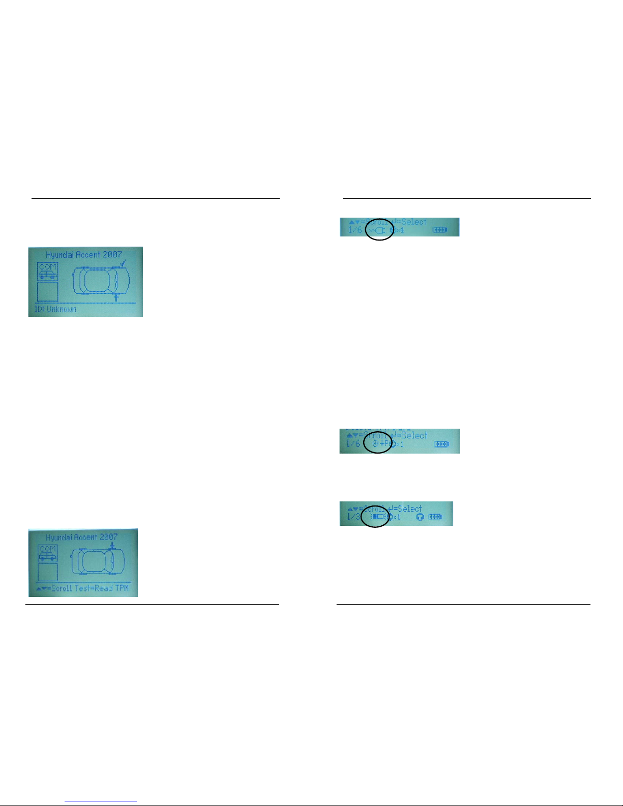
TPM Not Found Response USB Indicator
If the search period expires without reading a TPM then the Bartec
Te
ch 400 will emit a single Audible Beep and indicate on the
display that no TPM was found.
This status line indicator confirms the Tech 400 is connected to the
USB port of a personal computer.
In 4 wheel mode, the test prompt arrow will not automatically
mo
ve to the next wheel. This helps to do a repeat test to confirm
the TPM failure. Use ‘Down’ key to move to the next wheel.
It has two states:
Indicates an initialisation of
communication with the pc
Indicates that communication
has been established.
If the TPM has been selected via a vehicle menu, the internal
database automatically displays the catalogue number of the
replacement part (if it is available).
Pressing the ESC Key will return the user back to the previous
me
nu/ screen.
The TPM Data will still be stored but will indicate that the TPM Failed
to
Read.
TPM Data Storage
The Tech 400 is capable of permane
ntly storing up to 5 TPM Data
records in 1 wheel mode.
In 1 wheel mode, duplicate successf
ul reads will update any
already stored records.
More than 5 reads will cause the last record to be overwritten.
In 4 wheel mode- where data records are stored against specific
whe
el locations- duplicate successful reads are identified when in
ODB communications mode.
If a repeat read against one wheel p
osition is required, then the up
arrow key should be used to force the screen pointer to the wheel
requiring a repeat.
Once communication has been established, results data can be
v
iewed on the pc via the Mass Storage Device feature (use the PC
explorer program)
When the USB lead is removed the USB icon will disappear.
The USB connection provides a limited battery charge capability.
Battery Indicator/ Charging
This status line Indicator provides an indicat
ion of the remaining
charge status of the battery.
As different TPM types will ‘use up’ differing amounts of energy, the
indicat
or can only provide estimates of remaining life left before a
recharge is required
There is plenty of power in the Battery
There is a moderate amount of
power
in the battery- charging shortly
is suggested.
There is little power left in the batterycharging is required.
The battery has almost run out
Page 9

Tech 400 User Guide R5 4/1/08
8
Tech 400 User Guide R5 4/1/08
21
Once a read is completed:-
The TPM id is briefly displayed, then the tool automatically moves
o
nto the next wheel position- the arrow moves around the
vehicle:-
Awaiting the next read
Once all 4 TPM’s have been read, results can be viewed,
exa
mined on a pc, or the communications sub menu can be
accessed (see ‘Vehicle Communication’ section.
When there is an insufficient amo
unt of power remaining in the
battery then the Bartec Tech 400 will flash its battery icon for two
seconds, save all of the TPM Data and then power itself off.
When the battery is being ‘fast charged’ the indicator segments
‘wa
lk;’ from left to right- see the charging paragraph.
Test Indicator
This status line Indicator only appears on the select by vehicle
menu
. It confirms that a vehicle has been sufficiently selected t o
fully identify the TPM type.
If the Indicator is not visible when navigating the vehicle screens,
th
en pressing the Test Key will read the last TPM Type read/
selected.
Note when selecting by vehicle, the Tech 400 will ‘look ahead’
and
display the test indicator when sufficient selection has been
made- this may be prior to all available options (e.g. model, year)
having been navigated.
Results Data Available Indicator
This status line Indicator confirms
that TPM data is available for
viewing on the screen (using the View TPM Data command from
the main menu) or via a PC when the Bartec Tech 400 is in its Mass
Storage Device mode (See Audit System on page
23).
The Tech400 only stores up to 5 TPM
data records at any one time.
When there is no data present, the TPM Data Indicator will not be
vi
sible.
Page 10
Tech 400 User Guide R5 4/1/08
20
Tech 400 User Guide R5 4/1/08
9
Charger Connected Indicator In 4 wheel mode, TPM data is briefly displayed just prior to the
arrow on the vehicle icon moving round to prompt that the next
wheel should be tested. TPM data is stored for future reference.
This status line indicator confirms a charger is connec
ted. Note
that if both a PC (via USB) and charger are connected, the USB
takes priority
To charge the battery, connect the charger and note the Tech
400 automatically turns on with the charger icon displayed.
From fully discharged, the charging sequence i
s a short period of
‘pre-charge’, followed by about 2 hours ‘fast charging’ followed
by a ‘topping up’ charge.
Pressing the ESC key will return the user back to the previous
me
nu/ screen.
During the fast charge phase, the indicator segments in the
ba
ttery icon will ‘walk’.
TPM Test Modes
To maximise battery life (no battery has an unlimited life when
spe
cified by discharge and charge cycles), it is recommended
that once the fast charge phase is complete, the Tech 400 is
further left on charge for a minimum of 1 hour, but no longer than
5 hours.
Once a TPM has been selected, a TPM read can be initiated by
pressing th
e Test Key.
A TPM read is also initiated using t
he ‘Enter’ key when at the end
of the vehicle selection menu.
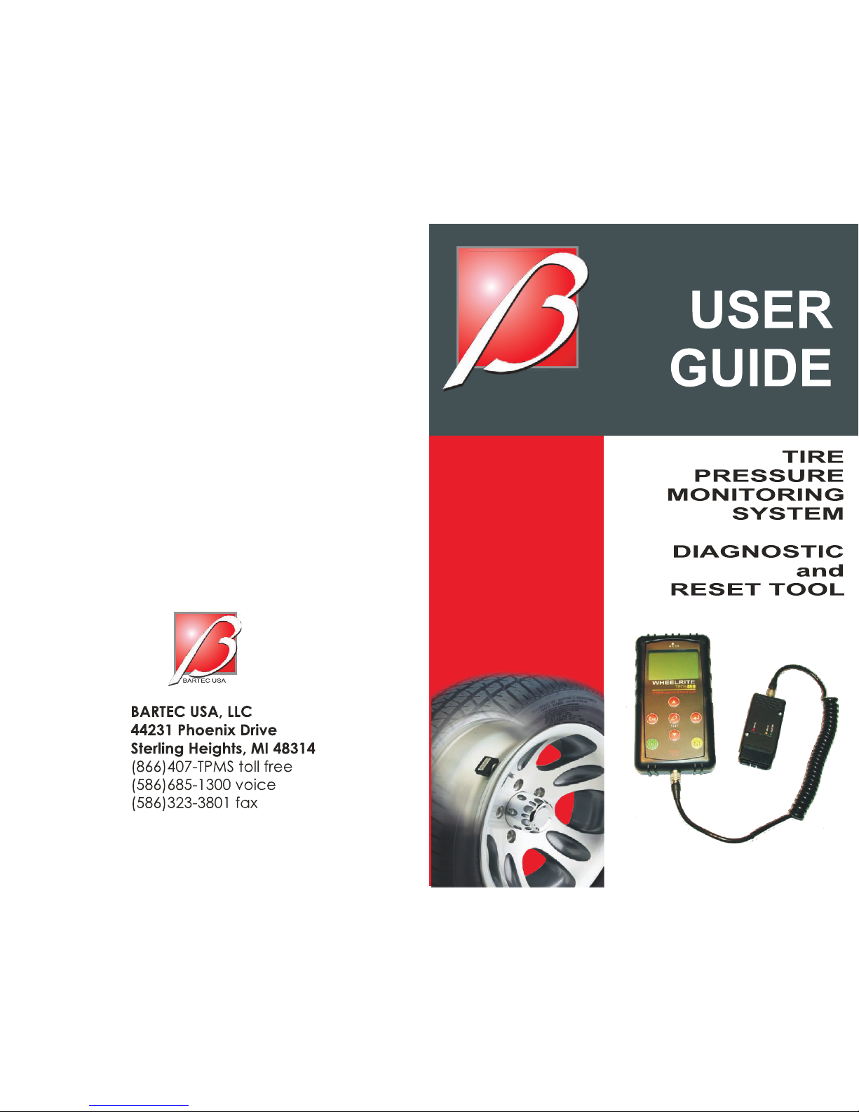
When a read is initiated In 4 wheel mode, a vehicle icon is first
pres
ented to prompt to test the correct wheel as part of an audit
Reduce Pressure Indicator
The example below is of a full vehicle audit. The vehicle was
selected using the ‘Select Vehicle’ menu and set to 4 wheel
mode.
(It is noted that this model provides communications to the
ve
hicle- see the ‘Vehicle Connection’ section of this document.)
This status indicator reminds the user that the chosen TPM (from
v
ehicle selection) requires a reduction in pressure to activate/test.
The first screen shows that the tool is ready to read the front left
T
PM - see the ‘TPM Activation/ Test’ section for the detail of how to
do this
Use magnet Indicator
This status indicator reminds the user that the chosen TPM (from
v
ehicle selection) requires a magnet to activate/test.
Page 11

Tech 400 User Guide R5 4/1/08
10
Tech 400 User Guide R5 4/1/08
19
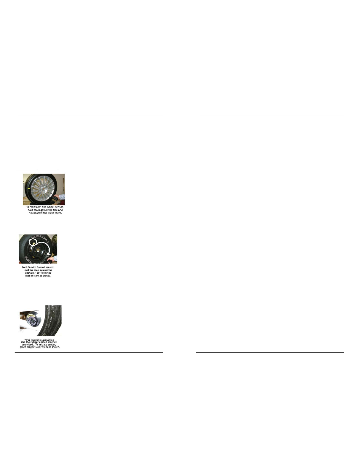
If the TPM requires tyre deflation (of the order of 10PSI), then
deflate the tyre, then place the tool alongside the stem whilst
pressing the test key.
RESULTS/ TEST DISPLAY AREA and DESCRIPTION
Depending upon the chosen mode (1 or 4 wheels), different
screens may be displayed- results and audit test screens are shown
below.
During testing, the screen confirms the TPM type being tested and
displays a pr
ogress bar.
Tick
indicates
read OK
The progress bar shows the maximum possible time for a successful
read- different makes of TPM respond at different speeds/ time
intervals.
COM indicates
vehicle
communications
are available
Arrow
indicates
next wheel
to be read
This TPM is not yet
read
? indicates
not yet read
TPM activation can be aborted at any time by pressing the ESC
key
. When the activation is aborted, the user will be returned to
the previous menu.
TPM Found Response
If a TPM of the indicated type is found, then the Bartec Tech 400
will
emit a series of tones that follows the pattern of received data.
RF indicates
wheel positionRight Front
X indicates
failed to
read
Depending upon the reading mode (1 or 4 wheel), results are
displayed in different manners.
In 1 wheel mode, TPM data will be stored and displayed
imme
diately.
When TPM fails, the
catalogue number is
displayed (where
available)
Page 12
Tech 400 User Guide R5 4/1/08
18
READING A TPM
Once a test mode has been decided upon - ( see page 5), the
mechanics of testing a TPM are as follows:-
TPM Activation/ Test
To test a TPM the tool should be placed alongside the valve stem
and
the ‘Test’ key pressed.
(Note with Ford TPM’s, the tool should be held 180°away from the
st
em.)
If the TPM requires a magnet, place the magnet over the stem
and
then place the tool alongside the stem- whilst pressing the test
key
Tech 400 User Guide R5 4/1/08
11
MENU SYSTEM
The Tech 400’s menu system provides a hierarchy of instructions
and commands.
The top line of the display will always indicate the currently
selec
ted menu.
The home key will always return t
o the Main Menu screen- with
‘Select by Vehicle’ highlighted
Menu Navigation
The menu system is navigated by use of the directional keys:
Up Arrow Key: Navigates up within the current menu
Down Arrow Key: Navigates down within the current menu
Enter (Right) Key: Navigates to the next menu or actions the
cu
rrently selected item.
Esc (Left) Key:
Navigates to the previous menu item.
All menus wrap around.
The enter key will primarily move to a sub menu. However in
‘
settings’ or ‘select by vehicle’ it will action the command or
commence a TPM test.
The test key will always commence a TPM test.
The Home key will always r
eturn to the main menu.
Page 13

Tech 400 User Guide R5 4/1/08
12
Tech 400 User Guide R5 4/1/08
17
Main Menu Settings Menu
This is the main screen- providing acce
ss to the main functional
items of the Tech 400.
When this is selected, the next screen gives settings options
The options are as follows:-
• W
heels To Test: - Select ‘1 wheel’ or ‘4 wheel’ test
The default entry position is page 1- select by vehicle (indicated
by
1/6 in the status line)
• TPM
ID – Select between Hexadecimal ID display or
Decimal ID display
• Pres
sure – Select between ‘PSI’, ‘kPA, or ‘Bar’ pressure
display
1. Selec
t by Vehicle
This Item is a sub menu, pressing the Enter Key will take the
us
er to the “Select by Vehicle” menu. The user should
select the vehicle make, model and year.
• Lang:
- Select language (supports English by default)
• Tem
perature: - Select between Celsius ( °C) or Fahrenheit
(°F)
• Di
splay Contrast – Select value that gives best display
contrast
2. Vi
ew TPM Data
This item is a sub menu, pressing the Enter Key will take the
us
er to the results screens. Press direction arrows to examine
the required results. In 4 wheel mode, each TPM has wheel
locations of LF; Left Front; RF; Right front; RR; Right rear; LR;
left rear.
Press ‘Enter’ to select and change the units for the selected
parameter.
3. Delete TPM
Data
Pressing the enter key will delete stored TPM results data.
4. Sett
ings
This item is a sub menu, pressing the Enter Key will take the
u
ser to the settings menu. This menu is on screen 4- not
shown on the screen above, but found using the ‘up’ or
‘down’ keys
5. Curr
ent TPM or vehicle selection
Page 14

Tech 400 User Guide R5 4/1/08
16
Tech 400 User Guide R5 4/1/08
13
All the TPM data is available for examination or printing from a pc
via the USB port. See the PC connection section of this documen t
on page
23.
This is an information line stating the current operation
mode – by TPM type or vehicle model. Pressing ‘Enter’ will
commence a test of this TPM / vehicle.
6. Selec
t by TPM Type
This Item is a sub menu, pressing the Enter Key will take the
us
er to the “Select by TPM” menu. Select the required TPM.
Select by Vehicle
When this is selected, the next screen prompts for selection by
mak
e, model, then year.
If a vehicle has more than 1 TPM type in a year- the TPM type has
a
lso to be selected.
(A vehicle model position ‘TRW Enable’ prompts for any TPM’s that
require ena
bling prior to installation- e.g. TRW’s on Hondas)
The selected vehicle is remembered by the tool when a test is
commenced.
Select By Make
Select by Model
Page 15

Tech 400 User Guide R5 4/1/08
14
Tech 400 User Guide R5 4/1/08
15
If the Tech 400 is in 4 wheel mode, results are displayed in the order
LF, RF, RR, and LR. Select by Year
E.g.
View TPM Data (Results) Menu
This menu- when selected- gives direct access to specific screens
t
hat display the TPM data. No menu page name is providedinstead, the screen provides all of the TPM Data available from the
TPM Type read; this may include: TPM ID (Hexadecimal & Decimal)
Battery State, Temperature and Pressure.
‘Up’ and ‘Down’ keys scroll through the TPM Data Items, the ‘Esc’
K
ey returns to the previous menu.
If no TPM data is available (or has been deleted), the screen will
display ‘U
nknown’
Not all TPM’s provide the same data.
Pressing the Enter Key will toggle the display format of the TPM ID
between Hexadecimal and Decimal (this does not affect the id
selection made in the settings menu)
If the Tech 400 is in 1 wheel mode, TPM Data is stored and
d
isplayed in chronological order - that is the newest TPM Data is
stored at the top of the menu.
E.g.
If the TPM failed to respond (it is likely faulty) - the screen will
displ
ay ‘No TPM Found’ during a search and ‘Failed to Read’ on
the results screen.
 Loading...