

Operating Instructions
Optical point sensor PSO+ and PSO Type: 17-85M6-1102.A00

Operating Instructions Optical point sensor PSO+ and PSO Type 17-85M6-1102.A00
M
Intended use
The PSO+ point sensor and the PSO point sensor are components of the BARTEC water detection system. They can be combined with the SCR
sensor cable and/or the PS point sensor. The RLW,
net
, RDW03 and RDA01 electronic monitoring
RLA
systems as well as corresponding accessories (see
catalogue) are also part of the BARTEC water detection system.
Product description
General information
The point sensor is used to detect electrically
non-conductive liquids such as oil, enabling the
location of the leak to be detected quickly.
Thanks to the special optics, it can operate reliably
also when facing metallic surfaces (e.g. oil catch
pan made of sheet steel).
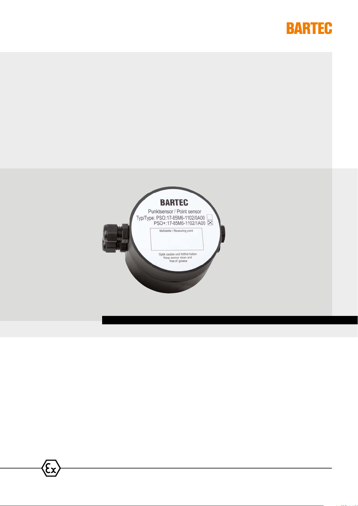
The PSO point sensor consists of a PVC sensor
enclosure with three spacer feet. In conjunction
with the BARTEC electronic monitoring system
(e.g. RDW, RDA, RLW or RLA), an alarm is signalled as from a leak height of 2 mm (height can
be adjusted using the screw feet).
The removable enclosure lid permits free access to
the terminals. Up to 50 sensors can be connected
in series. An integrated final resistance makes it
possible to monitor cable breaks.
The integrated load relay can operate actuators,
such as a check valve, directly on site. A second
changeover contact reports the circuit state to the
electronic monitoring system
Dierence between PSO+ and PSO
The PSO+ point sensor and PSO can be supplied
centrally with DC 24 V via the signal cable. It is
similarly possible to provide a decentralised power
supply by means of a commercially available plugin power supply unit.
With its additional terminal block, the PSO+ point
sensor can be combined with the SCR and PS sensors as required. In addition, this terminal block
and the integrated series resistors with R = 62 Ω
corresponding to 10 m sensor cable permits the
positioning function (with RLA
net
or RLW).
Safety instructions
• Before commissioning, please make certain
that the PSO+ and the PSO are suitable for the
designated use.
• For electrical installations, the pertinent
installation and operating regulations must
be followed (e.g. DIN VDE 0100 series or
other relevant national regulations).
• All general statutory regulations and other
binding guidelines on occupational health and
safety, accident prevention and environmental
protection must be complied with.
Assembly and commissioning
Assembly
The device must be positioned in a suitable place
where leaked liquid can collect. This is aided by a
catch pan with a ridge.
Installation
The device must be connected according to the circuit diagram, complying with the specified current/
voltage data. The ends of the conductors should be
appropriately prepared when connecting stranded
or finely stranded conductors.
Plug-in connections on the installation path must be
laid so they remain dry. For this purpose, the customer must insert spacers between the conductor
and the ground when monitoring areas.
Commissioning
The device may only be operated in a clean and undamaged condition. If damage is visible, the device
must be taken out of service and corresponding
repair measures must be initiated.
Commissioning must be performed in the following
steps:
• Connect the device to the power supply
• The green LED indicates that voltage is ON
• The red LED signals that the relay is active
(fail-safe circuit), when the optics are in the
open
• If the optics are immersed in the leaked liquid,
the relay sinks and the red LED is extinguished
Operation, maintenance
The company operating an electrical installation
must keep the operating equipment in good condition, must operate and monitor it as intended,
and must carry out maintenance and repair work.
All electrical equipment must be selected according
to its suitability. Applicable laws and guidelines must
be followed before putting it back into operation.
The specified safety instructions must be observed
before maintenance and/or troubleshooting.
It is necessar y to ensure that the optics of the PSO+
and of the PSO are kept clean and free of grease at
intervals that are suitable considering the degree of
soiling or dust to be expected.
Alarm management
Alarm output
The isolated relay output is primarily used as group
alarm output in the closed current/NC = normally
closed” operating mode. This means the contact
remains closed (relay is activated) as long as there
are no faults. This operating principle enables wire
breaks and power failures to be detected (1).
Function table
Leaking fluid not available available
PSO+/PSO
Operating condition
LED rot
„ready“
Relay coil current currentless
Relay contact
NO - C
Relay contact
NC - C
ready alarm
ON OFF
closed (1) open
open closed (2)
Measuring circuit monitoring
The connected point sensor is transmitted to electronic monitoring system (e.g. RDW, RDA, RLW or
RLA) via the relay contact NC - C. This also allows
the parallel connection of several point sensors (2).
In addition, the measuring circuit is monitored for
the following errors:
• Interruption of the measuring circuit
If this error occurs, the load circuit is opened and a
corresponding fault message generated.
Reservation Technical data subject to change without notice. Changes, errors and misprints may not be used as a basis for any claim for damages.
11-85M6-7D0001/B-11/2017-EHT-414087
www.bartec.de
BARTEC
DE 2/4

Operating Instructions Optical point sensor PSO+ and PSO Type 17-85M6-1102.A00
M
Technical data
Measuring method Visual: from 2 mm;
Can be adjusted higher
using screw feet
Ambient
temperature range
-25 °C to +50 at
5 % to 95 % air humidity
(non-condensing)
Optics und screw feet
(leaked liquid):
-25 °C to +80 °C
-40 °C to +125 °C
(on request)
Storage temperature -30 °C to +60 °C
Enclosure PVC
Terminals Screw terminals;
max. 1.5 mm²
Dimensions Ø 80 x 70 mm (D x H))
without cable glands
Fixing Free-standing,
floor installation
Protection class IP 65/67
Installation position Upright, optics pointing
straight down
Weight PSO+: approx. 270 g
PSO: 240 g
Electrical data
Rated voltage DC 24 V +/-10 %,
0.4 W
Outputs Group alarm relay,
2 changeover contacts
DC-13: 1 A, 24 V
Fail-safe, relay is
activated
Change-over contact:
NO – C terminals open if
leak is detected
Internal display LED green: voltage ON
LED red: relay activated,
no leak
Electrical connection/device connections
PSO+
-X1 (screw terminals, for series connection,
via installation cable, e.g. LIYY)
Terminals 1,
(+R = 62 Ω) 5
Measuring circuit
e.g. LIYY white
Terminals 2, 6 Reference measuring circuit
e.g. LIYY brown
(for positioning)
Terminals 3,
(+R = 62 Ω) 7
Measuring circuit
e.g. LIYY green
Terminals 4, 8 Reference measuring circuit
e.g. LIYY yellow
(for positioning)
Terminals 5, 7 Integrated terminal resistor
220 kΩ
Is removed during series
connection, apart from last
PSO+
Last PSO+ with terminal
resistor for RDA or RDW
Last PSO+ terminal jumpers
(5/6 and 7/8) for RLA
net
or
RLW
-X2 (Screw terminals, power supply and floating
changeover contacts via installation cable, e.g.
LIYY)
Terminals + DC 24 V e.g. LIYY white
Terminals - 0 V e.g. LIYY brown
Terminals 1, 4 Relay NO. LIYY green
Terminals 2, 5 Relay NC.
Terminals 3, 6 Relay C. LIYY yellow
-X3 (Screw terminals, optical sensor)
Terminals 1 red
Terminals 2 green
Terminals 3 blue
Terminals 4 N/C
By way of example, the wiring diagram shows the
connection of two PSO+ to the RLA
net
monitoring
unit:
• Can be combined with SCR sensor cable or
point sensor by means of PS printed circuit
board –X1; as a result, locating function is
possible
• Measuring circuit ended using terminal jumpers
(or end plugs for SCR)
• Load (e.g. a valve) can be switched o on site
using floating changeover contact
• Decentralised power supply possible
Connection diagram PSO+ (example)
Reservation Technical data subject to change without notice. Changes, errors and misprints may not be used as a basis for any claim for damages.
11-85M6-7D0001/B-11/2017-EHT-414087
www.bartec.de
BARTEC
DE 3/4

Operating Instructions Optical point sensor PSO+ and PSO Type 17-85M6-1102.A00
M
Electrical connection/device connections
PSO
-X2 (Screw terminals, power supply and floating
changeover contacts via installation cable, e.g.
LIYY)
Terminals + DC 24 V e.g. LIYY white
Terminals - 0 V e.g. LIYY brown
Terminals 1, 4 Relay NO. LIYY green
Terminals 2, 5 Relay NC.
Terminals 3, 6 Relay C. LIYY yellow
Terminals 2, 3 Integrated terminal resistor
220 kΩ, is removed for series
connection, except for the
last PSO
Connection diagram PSO (example)
-X3 (Screw terminals, optical sensor)
Terminals 1 red
Terminals 2 green
Terminals 3 blue
Terminals 4 N/C
By way of example, the wiring diagram shows the
connection of two PSO to the RDA01 monitoring
unit:
• No locating function possible
• Measuring circuit ended using final resistance
• Load (e.g. a valve) can be switched o on site
using floating changeover contact
• Decentralised power supply possible
Location diagram Terminal strip
PSO/PSO+ only PSO+
x 3x 2
X2E
X2D
X2C
x 1x 1
x 1
x 2
Service Address
BARTEC GmbH Max-Eyth-Str. 16 97980 Bad Mergentheim Germany Phone: +49 7931 597 0 info@bartec.de www.bartec.de
Reservation Technical data subject to change without notice. Changes, errors and misprints may not be used as a basis for any claim for damages.
11-85M6-7D0001/B-11/2017-EHT-414087
Reservation Technical data subject to change without notice. Changes, errors and misprints may not be used as a basis for any claim for damages.
www.bartec.de
BARTEC
DE 4/4
 Loading...