

Barrus Shire 15 15 CB, Shire 15 15 WB, Shire 15 15 RB, SHIRE 15 20 CB, SHIRE 15 20 RB User Manual
...
SHIR CANAL, WORK AND RIVER BOAT
ENGINE MANUAL
For the following engine models:
Shire 15 15 CB / WB / RB
SHIRE 15 20 CB / WB / RB
Please read in conjunction with the PRM Gearbox Manual
Enter your engine identification details in the spaces provided above.
E. P. BARRUS LIMITED, Launton Road, Bicester, Oxfordshire. OX26 4UR
Tel: 01869-363636 Fax: 01869-363610 www.barrus.co.uk
RDG603A13 – Issue 7 – Shire 15 Manual 15_20 – CB_WB_RB
Page 2 of 55
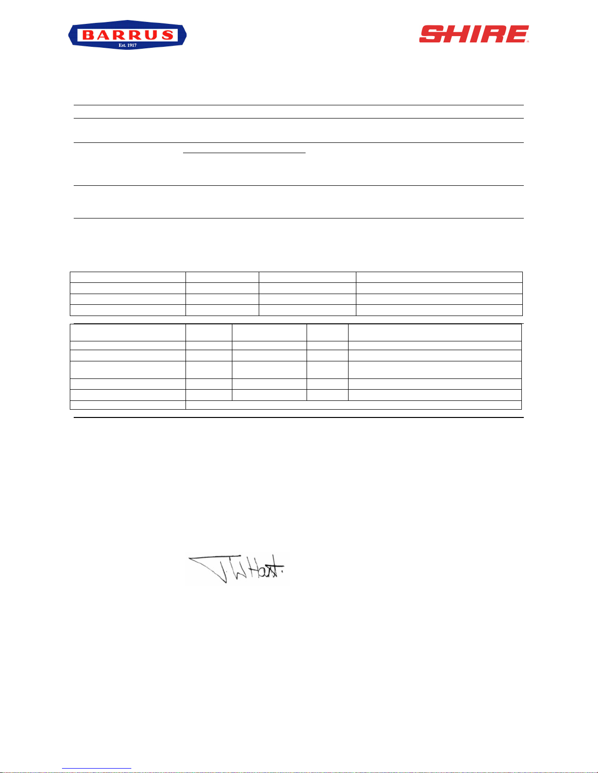
Declaration of Conformity for Recreational Craft Propulsion Engines to the
Directive No 2013/53/EU
Name of Engine Manufacturer: E.P.Barrus LTD
Name of Authorised Representative: E.P.Barrus LTD
Address: E.P.Barrus LTD, Launton Road, Bicester, Oxon, OX26 4UR, England
Name of Notified Body for exhaust emission assessment: HPi Verification Services Ltd
Address: The Manor House, Howbery Park
Town: Wallingford Post Code:OX10 8BA
Country: United Kingdom ID Number: 1521
Conformity assessment module used for exhaust emissions: B+C B+D B+E B+F G H
Or engine type-approved according to: Directive 2013/53/EU
Other Community Directives applied:
Description of Engine(s) and Essential Requirements
Engine Type: Inboard Engine Fuel Type: Diesel
Combustion Cycle: 4 Stroke
Identification of Engine(s) covered by this Declaration of Conformity
Engine Model
Engine Type
Engine Family code
Type Approval Certificate Number
Shire 15 15 CB/RB/WB
2M78
M78
HPiVS/R1105-002-I-02
Shire 15 20 CB/RB/WB
3M78
M78
HPiVS/R1105-002-I-02
Essential Requirements
Standards
Other normative
document/method.
Technical
file
Specify in more detail
*= Mandatory standard.
Annex 1.B- Exhaust Emissions
B.1 Engine Identification
R RCD (II)
R
2013/53/EU
B.2 Exhaust emission
requirements
R*
* EN ISO 8178- 1:1996
B.3 Durability
R
2013/53/EU
B.4 Owners Manual
R R
ISO10240
Annex 1. C- Noise Emissions
See Declaration of Conformity of the craft in which the engine(s) has(have) been installed
This declaration of conformity is issued under the sole responsibility of the manufacturer. I declare on behalf
of the engine manufacturer that the engine(s) [is (are) in conformity with the type(s) for which above
mentioned EC type-examination or type approval certificate(s) has (have) been issued and]1 will meet the
exhaust emission requirements of Directive 2013/53/EU when installed in a recreational craft, in accordance
with the engine manufacturer’s supplied instructions and that this (these) engine(s) must not be put into
service until the recreational craft which it is (they are) to be installed has been declared in conformity with the
relevant provisions of the above mentioned Directives.
Tim Hart
Sales Director
Signed: Bicester, UK
Date: 18/01/2016
RDG603A13 – Issue 7 – Shire 15 Manual 15_20 – CB_WB_RB
Page 3 of 55
PLEASE NOTE:
This manual has been compiled to help you to operate your engine and its associated parts
with safety and pleasure. Please read it carefully and familiarise yourself with the engine
and its parts before operation.
E.P.Barrus reserve the right to change the specification of its products and manuals without
prior notice.
Depending upon the equipment specification of the engine and accessories fitted, there
may be discrepancies with the information presented in this handbook. No claims may be
pursued in this respect.
WARNING:
THIS MANUAL FORMS AN INTEGRAL PART OF THE ENGINE IT ACCOMPANIES, IF
A TRANSFER OF TITLE OCCURS, IT MUST ALWAYS BE HANDED OVER TO THE
NEW OWNER.
WARRANTY
This Limited Warranty provides coverage for:
• Leisure Applications: Two (2) years from the date of warranty registration.
• Commercial Applications: One (1) year or a maximum of 1000 hour from the date of
warranty registration (whichever occurs first).
The repair or replacement of parts, or the performance of service under this warranty, does
not extend the life of this warranty beyond its original expiry date.
To ensure that you have been registered for your warranty, please ask your Boat-Builder or
Engine supplier to provide your portion of the registration form.
The Warranty will only apply if the following have been carried out:
1/ The Installation Check List in the Installation Section has been fully completed.
2/ The boat builder or engine installer has completed the Boat Builder Section on the

RDG603A13 – Issue 7 – Shire 15 Manual 15_20 – CB_WB_RB
Page 4 of 55
Service Record Card (located at the back of this manual) regarding hand over and
commissioning of boat.
3/ The registration form has been completed and returned to E.P Barrus.
PRM gearboxes are covered by a two (2) year warranty.
Engine alternator, starter motor and electrical components are only covered by a one (1)
year warranty.
CONDITIONS THAT MUST BE MET IN ORDER TO OBTAIN WARRANTY COVERAGE
Warranty coverage is only available from an authorised dealer in the country in which the
sale occurred. Routing maintenance outlined in the Owner’s Manual must be performed
using genuine parts in order to maintain warranty coverage. If the customer performs
maintenance, Barrus reserves the right to make future warranty coverage possible only with
proof of proper maintenance.
WARRANTY CLAIMS
Warranty claims shall be made by an authorised dealer or boat builder.
The dealer or boat builder will then arrange for the inspection and any necessary repairs. If
the repairs carried out are not covered by the warranty, the purchaser shall pay for all
related labour and material, and any other expenses associated with that service.
WHAT IS NOT COVERED
This limited warranty does not cover routine maintenance items, adjustments, normal wear
and tear, damage caused by abnormal use, operation of the product in a manner
inconsistent with the recommended operation/duty cycle section of the Owner’s Manual,
accident, submersion, improper installation (proper installation specification and techniques
are set forth in the Operations and First time running sections in this manual), use of an
accessory or part not manufactured or sold by us, or alteration or removal of parts.
Expenses related to crane-out, launch, towing, storage, telephone, rental, inconvenience,
slip fees, insurance coverage, loan payments, loss of time, loss of income, or any other
types of accidental or consequential damages are not covered by this warranty.
Engine electrical systems fitted with alternator boost charge systems or any other electrical
management systems are not covered by warranty.
Engine and fuel equipment is not covered by warranty if bio-diesel is used in the fuel
system. Also if no type of water trap is incorporated into fuel system.

RDG603A13 – Issue 7 – Shire 15 Manual 15_20 – CB_WB_RB
Page 5 of 55
Index
Page
SECTION 1 – Safety Precautions ................................................................... 8!
1.! General ......................................................................................................................... 8!
2.! Lifting ............................................................................................................................ 8!
3.! Rotating Shafts and Belts ............................................................................................. 8!
4.! Exhaust System ........................................................................................................... 8!
5.! Launching and Lifting Boats ......................................................................................... 8!
6.! Batteries ....................................................................................................................... 8!
SECTION 2 – Engine Identification .............................................................. 10!
SECTION 3 – Installation ............................................................................... 11!
1.! Ventilation ................................................................................................................... 11!
2.! Engine Beds ............................................................................................................... 11!
3.! Cooling System (Canal Boats with Skin Tanks) ......................................................... 11!
4.! Skin Tanks (Canal Boats) ........................................................................................... 11!
5.! Engine Cooling Water Connections ........................................................................... 12!
6.! Pressurised Water Header Tank ................................................................................ 12!
7.! Shaft Connection and Propeller Selection .................................................................. 14!
8.! Engine Anti-Vibration Mounts ..................................................................................... 14!
9.! Engine Alignment ....................................................................................................... 15!
10.! Electrics ...................................................................................................................... 16!
11.! Electrical Options ....................................................................................................... 16!
12.! Engine Oil ................................................................................................................... 16!
13.! Fuel ............................................................................................................................ 17!
14.! Coolant ....................................................................................................................... 17!
15.! Calorifier ..................................................................................................................... 18!
16.! Control Cables ............................................................................................................ 19!
17.! Domestic Battery Bank ............................................................................................... 19!
18.! Control Panel .............................................................................................................. 20!
19.! Exhaust System (Canal Boat) .................................................................................... 21!

RDG603A13 – Issue 7 – Shire 15 Manual 15_20 – CB_WB_RB
Page 6 of 55
20.! Exhaust System (Work Boat / River Boat) ................................................................. 22!
21.! Hydraulic Drive Transmissions ................................................................................... 24!
22.! Installation Check List ................................................................................................ 25!
SECTION 4 – Operation ................................................................................. 26!
1.! Starting the engine for the first time ........................................................................... 26!
2.! Starting Procedure ..................................................................................................... 27!
3.! Stopping Procedure .................................................................................................... 27!
4.! Refuelling ................................................................................................................... 28!
5.! Diesel Fuel Additive .................................................................................................... 28!
6.! Exhaust Back Pressure .............................................................................................. 28!
7.! Single Lever Side Mount Operation - Optional (RDG9210055) ................................. 28!
SECTION 5 – Service Procedure .................................................................. 29!
1.! Daily Maintenance ...................................................................................................... 29!
2.! Engine Oil and Filter Change ..................................................................................... 29!
3.! Air Filter Check and Change ...................................................................................... 29!
4.! Gearbox Oil Change ................................................................................................... 30!
5.! Disposal of Oil and Related Items .............................................................................. 31!
6.! Fuel Filter Drain – Shire 15 15/20 .............................................................................. 31!
7.! Fuel Filter Change ...................................................................................................... 32!
8.! Fuel System Bleeding ................................................................................................ 32!
9.! Cooling System .......................................................................................................... 32!
10.! Belt Adjustment .......................................................................................................... 33!
11.! Belt Maintenance ........................................................................................................ 34!
12.! Belt Replacement ....................................................................................................... 34!
13.! Control Panel Maintenance ........................................................................................ 34!
14.! Sacrificial Anode Change ........................................................................................... 35!
15.! Raw Water Pump Impellor Change (Work Boat & River Boat) .................................. 35!
16.! Engine Heat Exchanger Tube Stack Flushing ............................................................ 36!
17.! Winterization of Seawater Cooling System (Work Boat & River Boat) ....................... 37!
SECTION 6 – Service Schedule .................................................................... 38!

RDG603A13 – Issue 7 – Shire 15 Manual 15_20 – CB_WB_RB
Page 7 of 55
1.! Specifications and Capacities .................................................................................... 38!
2.! Service Intervals ......................................................................................................... 38!
SECTION 7 – Wiring Diagrams ..................................................................... 40!
1.! Engine Wiring Diagram Shire 15 15/20 ...................................................................... 40!
2.! Standard Control Panel Wiring Diagram .................................................................... 41!
3.! Deluxe Control Panel Wiring Diagram (Additional Option – SS1551) ........................ 42!
4.! RDG20710110 – Standard Control Panel .................................................................. 43!
5.! RDG20710111 – Deluxe Control Panel (Additional Option – SS1551) ...................... 43!
6.! Overall Dimensions of the Control Panels .................................................................. 44!
SECTION 8 – Technical Data ........................................................................ 45!
SECTION 9 – General Arrangement Drawings ............................................ 47!
1.! General Arrangement Shire 15 15 Canal Boat ........................................................... 47!
2.! General Arrangement Shire 15 15 River Boat ............................................................ 48!
3.! General Arrangement Shire 15 20 Canal Boat ........................................................... 49!
4.! General Arrangement Shire 15 20 River Boat ............................................................ 50!
SECTION 10 – Dealer List ............................................................................. 51!
SECTION 11 – Shire Service Parts ............................................................... 53!
SECTION 12 – Shire Service Record Card .................................................. 54!
RDG603A13 – Issue 7 – Shire 15 Manual 15_20 – CB_WB_RB
Page 8 of 55
SECTION 1 – Safety Precautions
1. General
It is the responsibility of the installer/operator to ensure that the finished installation
complies with the relevant Health & Safety requirements and the recreational craft directive
before commissioning.
Ensure that the engine battery isolator switch is in the off position and the key removed
from the control panel before carrying out any maintenance or repairs.
2. Lifting
The Lifting points supplied with the engine are for lifting the engine/gearbox only. A suitable
spreader bar must be employed to prevent over-stressing either bracket during any lift.
3. Rotating Shafts and Belts
The engine and its accessories are not intended to be put into operation until they are
integrated into the boat as a whole. No person should be in the engine compartment and
the engine cover or deck hatches should be closed whilst the engine is running.
4. Exhaust System
Exhaust gases may have temperatures as high as 650°C and contain elements which are
harmful if ingested.
It is therefore essential that exhaust systems are gas tight and lagged to prevent accidental
burning.
5. Launching and Lifting Boats
Care must be taken when launching or craning new boats into or out of the waterway, so
that water does not enter the engine via the exhaust system or air vents. It is recommended
that these are blocked temporarily whilst undertaking this procedure.
6. Batteries
WARNING:
EXPLOSIVE GASES / SULPHURIC ACID
• Batteries can produce explosive gases; keep sparks and flames away from the
battery.
NO SMOKING
• Batteries contain sulphuric acid; if splashed on skin or eyes, flush well with water and

RDG603A13 – Issue 7 – Shire 15 Manual 15_20 – CB_WB_RB
Page 9 of 55
seek medical advice.
• Keep battery tops and battery compartment ventilated at all times
• If disconnecting the battery; remove the earth lead FIRST; and re-connect it last.
• If charging the battery; ensure that the charger is switched off before connecting and
disconnecting.
• Do not tip the battery on its side.
• Please see label on battery or manufacturer’s instructions for specific information.

RDG603A13 – Issue 7 – Shire 15 Manual 15_20 – CB_WB_RB
Page 10 of 55
SECTION 2 – Engine Identification
Please quote the engine identification number during any enquiry or when ordering spare
parts. Use the space below to record these details.
This can be found engraved into the brass plate on the top of the engine rocker cover and
stamped to the crankcase next to the starter motor.
Note: Canal Boat Engines (CB) do not have identification initials on the engraved plate.
An example of the engine identification plate is shown below (Figure 1):
Description of Models:
CB: Canal Boat Engine: Keel cooled dry exhaust manifold.
WB: Work Boat Engine: Seawater / Heat Exchanger cooled, dry exhaust manifold
with either dry exhaust system (same as a Canal Boat) or
water injected exhaust system.
RB: River Boat Engine: Can also be used for sea going applications. Seawater / Integral
exhaust manifold, heat exchanger cooled. Water injected exhaust system.
Note: There are a number of optional extras that may be fitted to an engine that are not
listed here.
SHIRE
1550$D$XXXXX
Indicates Model Type or Optional Extras:
RB = River Boat
WB = Work Boat
D = Deluxe Panel
3 = 3:1 Ratio Gearbox
Engine Model
Build Number
Serial Number
Figure 1: Engine Identification Badge

RDG603A13 – Issue 7 – Shire 15 Manual 15_20 – CB_WB_RB
Page 11 of 55
A list of common item service part numbers can be found in Section 11, Shire service parts.
SECTION 3 – Installation
1. Ventilation
• All internal combustion engines radiate heat and require cool, clean air to aid
complete combustion.
• Please Ensure that adequate engine room ventilation is provided, by fitting at least
two vents of an aperture of not less than 10,000mm2 each (16in2).
An allowance must be made for any rills, louvres or bends placed in the airflows and
generally an increase of 25% in area is sufficient to overcome any restriction
problems.
2. Engine Beds
• These should be a minimum of 10mm thick, extended rearward and be welded to the
hull and forward to the bulkhead. Webs or gussets must be welded in place midway
to prevent flexing.
3. Cooling System (Canal Boats with Skin Tanks)
• Ensure pipe work to and from the skin tanks is of sufficient bore. A minimum of
28mm (11/6“) is recommended Ensure tight bends and elbows are avoided or kept to
a minimum.
4. Skin Tanks (Canal Boats)
The ideal skin tank internal thickness is between 50 and 75mm, the table below will indicate
a suitable tank size. However, volume will not compensate for lack of surface area. It
should be recognised that fitting a large calorifier will increase the theoretical cooling
capacity only until it is up to temperature. It is unlikely that a boat on the inland waterways
will operate at full power for long periods of time.

RDG603A13 – Issue 7 – Shire 15 Manual 15_20 – CB_WB_RB
Page 12 of 55
Height
Length
Air Bleed Points
Coolant to
Engine
Coolant from
Engine
Figure 2: Skin Tank Flow Diagram
Recommended Skin Tank Size
Engine
HP
KW
Skin tank surface
area m2
Suggested
Height mm
Suggested Length mm
15
15
11
0.75m
600
1000
20
20
15
0.75
600
1250
Note: Skin tank size must be increased by approx. 10% if a hydraulic drive transmission is
fitted.
5. Engine Cooling Water Connections
For Canal Boats:
These are on the Left hand (Port) side of the engine:
• Shire 15 and 20 28mm (1 1/6”) OD
• The hose must be capable of taking water at temperatures in excess of 90°c. The
hose should also be non-collapsible.
For River Boats & Workboats:
• Seawater inlet hose size: 19mm (¾”)
• Water cooled exhaust hose size: 50mm (2”)
6. Pressurised Water Header Tank
• The pressurised header tank should be mounted higher than the level of the engine,
no less than 300mm, and no more than 1m from the engine, to prevent cooling
system air locks.
• The two hosetails on the plastic header tank have different hole diameters. Please

RDG603A13 – Issue 7 – Shire 15 Manual 15_20 – CB_WB_RB
Page 13 of 55
make sure they are connected the correct way around as per Figure 3 and Figure 4.
Note: Not fitted to RB engines
Figure 3: Shire 15 20 Canal Boat Header Tank Connections
Figure 4: Shire 15/20 Work Boat Header Tank Connections
Large ID Hole
Small ID Hole
Large ID Hole
Small ID Hole
RDG603A13 – Issue 7 – Shire 15 Manual 15_20 – CB_WB_RB
Page 14 of 55
7. Shaft Connection and Propeller Selection
• Some type of flexible coupling must be used to connect the gearbox output flange to
the propeller shaft flange.
• Please note, underperforming engines will not be covered under warranty if the
cause of the poor performance is found to be the use of an inappropriate propeller.
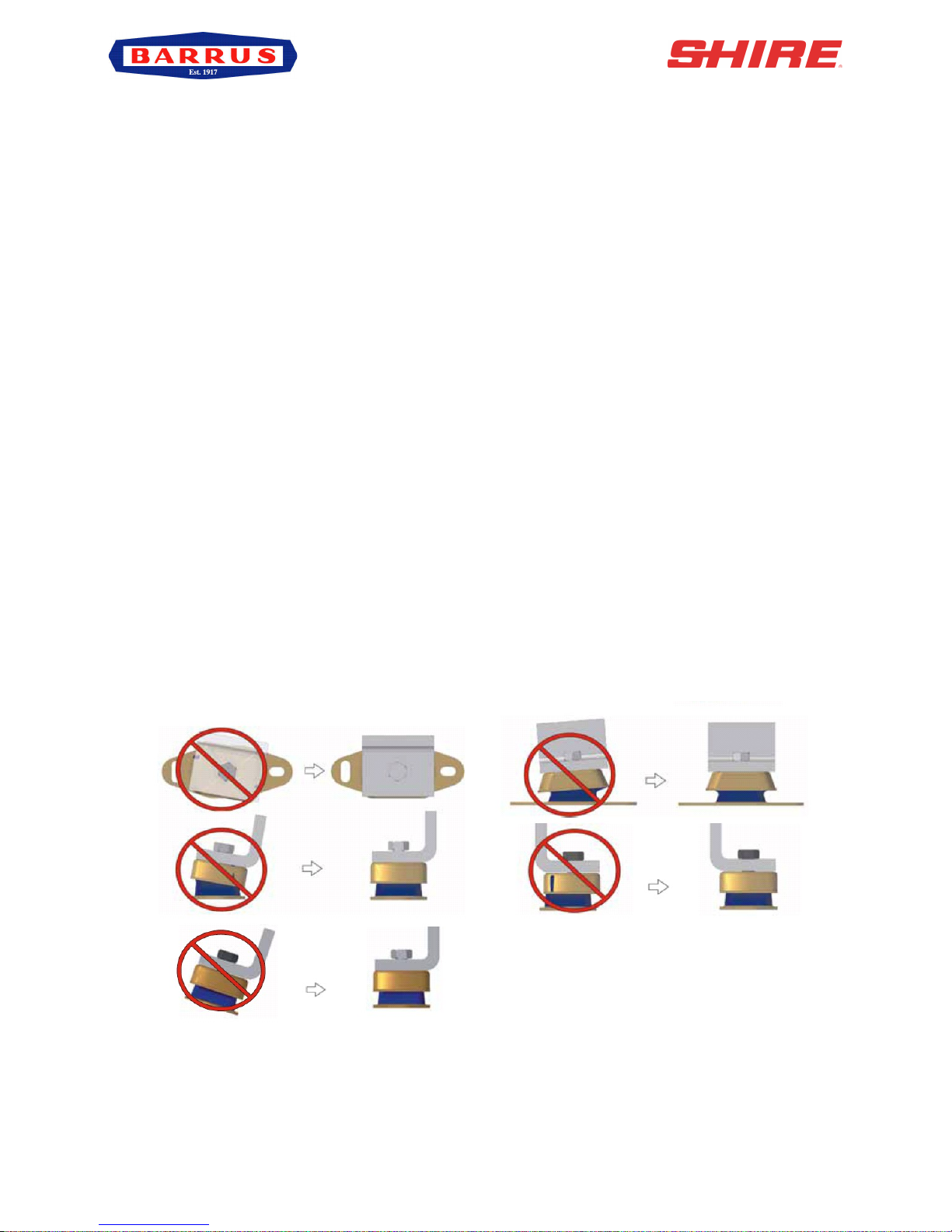
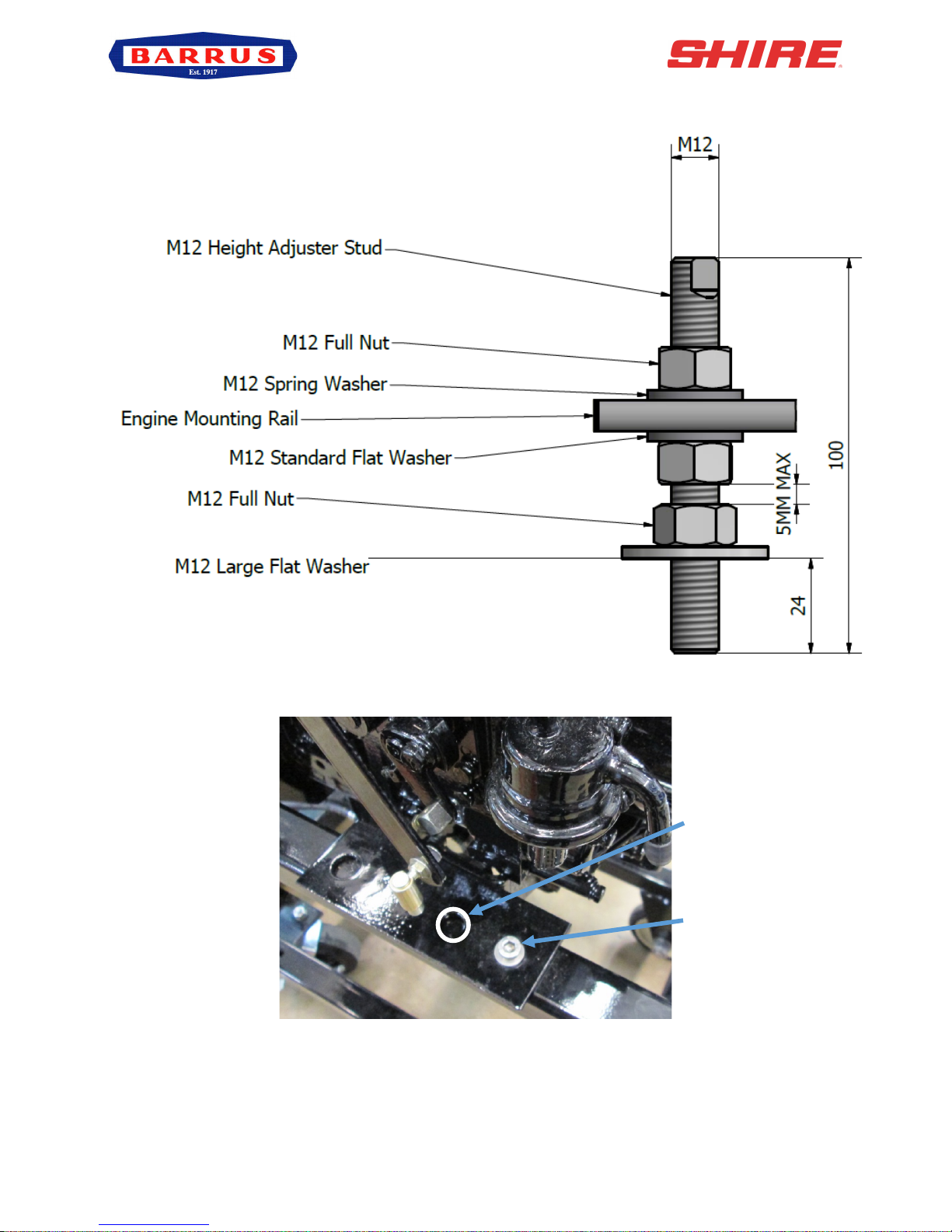
8. Engine Anti-Vibration Mounts
• Ensure that the engine feet do not end up at the top of the thread on the engine
mounts, this puts undue pressure on them and can result in excessive engine
movement and premature mount failure. If this is a problem put steel packing plates
under the mounts.
• Ensure that the engine has been installed for at least 24 hours before shaft
alignment is checked, to allow the mounts time to settle under the engine weight.
• Ensure that the anti-vibration mount centre screw is sufficiently raised so as not to
touch the engine bed. If this occurs, excessive engine vibration will be experienced
through the hull.
• Alternative mounting holes for the anti-vibration mounts are available. Your new
engine maybe replacing an old engine so suitable holes may align with your existing
mounting holes
• For the best results, the mounting screw for the front mount should go into the most
forward hole in the bracket. The mounting screw for the rear mount should go into
the most rearward hole in the bracket.
Figure 5: Correct Anti-Vibration Mount Installation
RDG603A13 – Issue 7 – Shire 15 Manual 15_20 – CB_WB_RB
Page 15 of 55
Figure 6: Correct Anti-Vibration Mount Installation
Figure 7: Anti-Vibration Mount Installation Points
9. Engine Alignment
• The gearbox output shaft flange and propeller shaft input flange must be almost
Alternative mounting
position if engine
compartment space is
Normal mounting position

RDG603A13 – Issue 7 – Shire 15 Manual 15_20 – CB_WB_RB
Page 16 of 55
perfectly aligned. A maximum of 0.05mm (0.002”) misalignment in any plane is
acceptable. Ensure alignment is rechecked after the first 4 hours of running, after the
first month and thereafter annually.
• If the engine is out of alignment it will result in excessive vibration and possible
damage to the stern tube and propeller shaft.
• Boats that are fitted with fully flexible drive couplings should still have the engine and
shaft alignment as close as possible. A dummy shaft may be required for this
purpose. Note: Some types of flexible shaft couplings require the input and output to
be misaligned, check with the coupling manufacturer’s installation instructions.
• Minimum clearance of 25mm between rails and engine beds.
10. Electrics
• Do not attach any part, hose or cable to the engine wiring harness. There is a
warning label attached to the harness to remind you of this.
• Connect the wiring extension harness multi plug to the panel plug and the other end
to the engine.
• Connect the start battery positive cable to the engine starter motor solenoid terminal.
• The starter motor battery cable must have a cross sectional area of at least 50mm2.
• For twin alternator engines, connect the domestic battery positive cable to the 70A
alternator B+ terminal (see wiring diagram). This ensures that the 50A alternator
charges the start battery and the 70A alternator charges the domestic battery,
removing the requirement for a split charging system or relay.
• Negative battery terminal must be connected to a common earth point.
11. Electrical Options
• Standard engine is a single 50A Alternator.
• Option 1, is a single 70A Alternator. (SS1491)
• Option 2, is Twin Alternators 50A and 70A (CB engine only)
• Electrically operated stop solenoid (energise to run). (SS1553 or SS1554)
• Deluxe Control Panel. (SS1551)
12. Engine Oil
• All Shire engines are supplied fully run in.
• Check oil levels in engine and gearbox before starting
• Use good quality engine oil SAE 10W / 40 API class CD.

RDG603A13 – Issue 7 – Shire 15 Manual 15_20 – CB_WB_RB
Page 17 of 55
WARNING:
ENGINE OIL WITH A HIGHER API CLASS THAN CD IS UNSUITABLE FOR CANAL
BOAT OPERATION AND WILL CAUSE ENGINE DAMAGE IF USED.
13. Fuel
• Ensure the main fuel tank is clear of dirt and water.
• A separate water trap must be fitted to all engine installations.
• Connect fuel feed return hoses from engine to main supply and return lines to main
fuel tank, ensuring they are connected the correct way around. The hose to the fuel
pump is the inlet.
• The engine hoses are supplied with 5/16” (8mm) OD metal hose tails and should be
securely fitted to the main supply and return pipes with compression fittings.
• The engine hoses should have sufficient slack to absorb engine movement without
placing strain on the hoses and be securely clipped to prevent accidental damage
and chafing.
• Loosen the bleed screw on the top of the primary fuel filter/water trap. Depress and
pump the spring loaded plunger on top of the fuel filter assembly. Close when fuel
begins to flow clearly (no bubbles). It is rarely necessary to bleed the injection pump
or injectors upon installation as the engine will already have fuel in it from the engine
run in and test procedure.
14. Coolant
• Prepare coolant mix of 50% clean tap water and 50% antifreeze. Please make sure
that the antifreeze used is suitable for the silicone hoses fitted to the engine.
• Open the calorifier taps (if fitted) to fill the calorifier system and displace air.
Canal Boats: To fill the cooling system for the first time, fill the skin tank via the inlet hose
connection or filler plug if fitted.
• Fill the engine through white plastic expansion tank.
Note: After running the engine for the first time, monitor the water level frequently as
trapped air bubbles may be expelled. Top up the system as necessary.
Workboats: Dry Manifold, fill the engine through the white expansion tank.
Note: After running the engine for the first time, monitor the water level frequently as
trapped air bubbles may be expelled. Top up the system as necessary.

RDG603A13 – Issue 7 – Shire 15 Manual 15_20 – CB_WB_RB
Page 18 of 55
Riverboats with Water Cooled Manifold: Remove filler cap on top of water cooled
exhaust manifold and fill cooling system through here. Run engine at idle for a few minutes
with cap removed to ensure air is removed and allow a 13mm (1/2”) air gap in top of
manifold to allow for expansion.
Note: Water Tap (CB & WB engines only) on side of engine must be opened to fill engine
and must be closed to the off position to run the engine. (Figure 8)
Figure 8: Water Tap on CB & WB Engines
15. Calorifier
For Canal Boats:
• The calorifiers are positioned as per (Figure 9)
Figure 9: Position of Calorifiers on a Canal Boat
For Work Boats:
• The calorifiers are positioned as per (Figure 10)
Figure 10: Position of Calorifiers on a Work Boat
Water Tap
Inlet
Outlet
Inlet
Outlet
Seawater
Pump

RDG603A13 – Issue 7 – Shire 15 Manual 15_20 – CB_WB_RB
Page 19 of 55
For River Boats:
• The calorifiers are positioned as per (Figure 11)
Figure 11: Position of Calorifiers on a River Boat
WARNING:
• The temperature of coolant flowing to the calorifier from the engine can be between
85 and 90°C. A blender valve must be incorporated in the calorifier/hot water system
outlet to lower the hot water temperature for domestic use.
16. Control Cables
• Connect engine speed control cable. With the engine off, ensure that the engine
speed control lever achieves full travel from idle to full speed. Adjust if necessary.
• Check the gearbox shift lever selects positively and that the drive direction
corresponds with the gearshift control lever. Ensure that the gearbox control lever
and the gearshift lever are both in neutral before connection. Adjust if necessary.
17. Domestic Battery Bank
Domestic battery banks that are too large create excessive loads on the domestic
alternator. Alternators running at maximum output for prolonged periods of time will
eventually fail prematurely; alternators that fail due to the battery bank being over the
maximum recommended size will not be covered by warranty.
Higher output additional alternators, or travel power kits are available: if larger battery
banks are required discuss your individual power requirements with the boat builder or
dealer.
• The maximum domestic battery bank is calculated using the following:
- Live aboard, three times domestic alternator, maximum output current.
- Weekend cruising or hire fleet use, three and a half times domestic
alternator, maximum output current.
Outlet
Inlet

RDG603A13 – Issue 7 – Shire 15 Manual 15_20 – CB_WB_RB
Page 20 of 55
Example 1:
Live aboard application fitted with a 70amp domestic alternator
3 x 70 = 210 ampere/hour maximum battery bank size
Example 2:
Weekend cruising or hire fleet application fitted with 50amp domestic alternator
3.5 x 50 = 175 ampere/hour maximum battery bank size.
Note: For boats with single alternators and using domestic batteries, it is strongly advised to
use a split charge relay system and separate batteries. This will ensure that the start battery
does not become discharged.
18. Control Panel
All Shire engines are supplied with high quality engine control panel that all show RPM and
hours run and include warning lights and a warning buzzer. The deluxe panels also have
additional gauges for the water temp, oil pressure and battery charging. The panels are
designed to be splash proof and are correctly installed with the gauges vertical. Do not
install so that they remain out in the open, or cover up when not on use.
The control panel engine tachometer is supplied already calibrated to measure correct
engine speed. If a new control panel, tachometer or alternative alternator is fitted, the tacho
will require re-calibrating.
Control Panel Calibration Procedure:
• Connect Control panel plug to engine wiring loom plug.
• Turn ignition on (do not start engine).
• Press and hold black button on rear of tacho until “H-“appears on the digital display
at the bottom of the tacho (on the front).
• When pressing and holding the black button on rear of tacho, the value displayed will
increase / decrease until the button is released. Then when pressing again it will
increase / decrease in the other direction. Keep doing this until the digitally
displayed value on the bottom of tacho reaches the correct value, according to the
type of alternator (see below table). This must be set to the alternator with blue and
black wire connected to it.
• Confirm settings to tacho meter reader.
• An optical tachometer is required to check the reading.
RDG603A13 – Issue 7 – Shire 15 Manual 15_20 – CB_WB_RB
Page 21 of 55
Barrus Alternator (Amps)
Barrus Tacho reading
50
10.50 – 11.00
70
15.00
50 & 70 (Twin Alts)
Only the 50 Amp alternator requires calibration
Alternative or non-standard alternators will require calibrating and checking by trial and
error, with a hand held tacho until the engine speed and indicated tachometer speed are
the same.
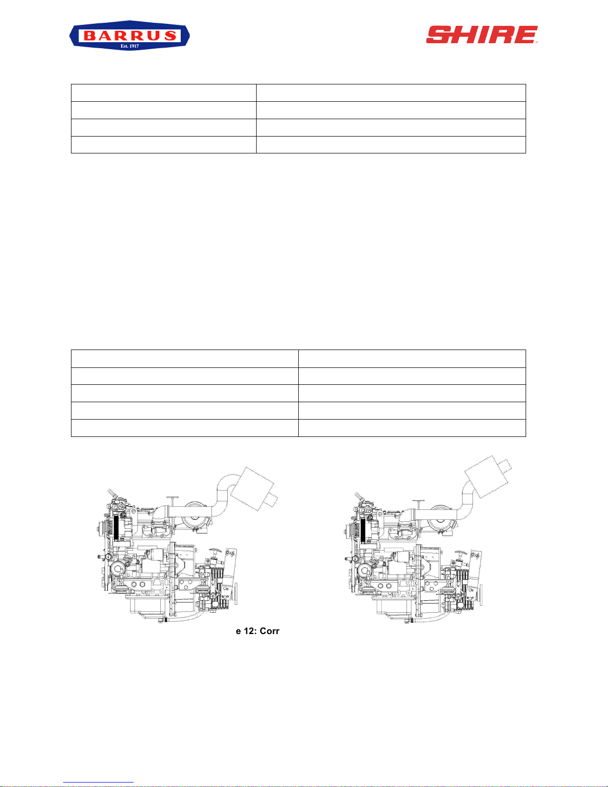
19. Exhaust System (Canal Boat)
The exhaust outlet size on the engine is 1½” BSP female. There must be a flexible exhaust
hose of suitable exhaust grade between the engine and the silencer or hull outlet. The
outlet must be above the waterline at all times. The exhaust fittings and silencer (if fitted),
must not be smaller than 1½” BSP. Exhaust silencers, flexible exhaust hose connections
and lagging blanket are all available as optional extras:
Part Description
Part Number
Exhaust Coupling 1½” x 1½” BSP
RDG1916
Exhaust Silencer DSA-38
RDG1911
Flexible Exhaust Hose (18”)
RDG1879
Blanket 18” Flexy Exhaust
RDG2477
Figure 12: Correct Installation of Exhaust
• Make sure the exhaust increases then decreases in height as shown in (Figure 12).
ü
X
RDG603A13 – Issue 7 – Shire 15 Manual 15_20 – CB_WB_RB
Page 22 of 55
20. Exhaust System (Work Boat / River Boat)
Use 50mm ID suitable marine flexible exhaust hose on the 20 Work Boat model engine.
The exhaust system must not be restricted in any way.
Note: If the engine is installed low down in the boat, below the outside water level, a system
such as a Lift Silencer with a siphon break system, must be used to prevent sea water from
flowing back down the exhaust and into the engine.
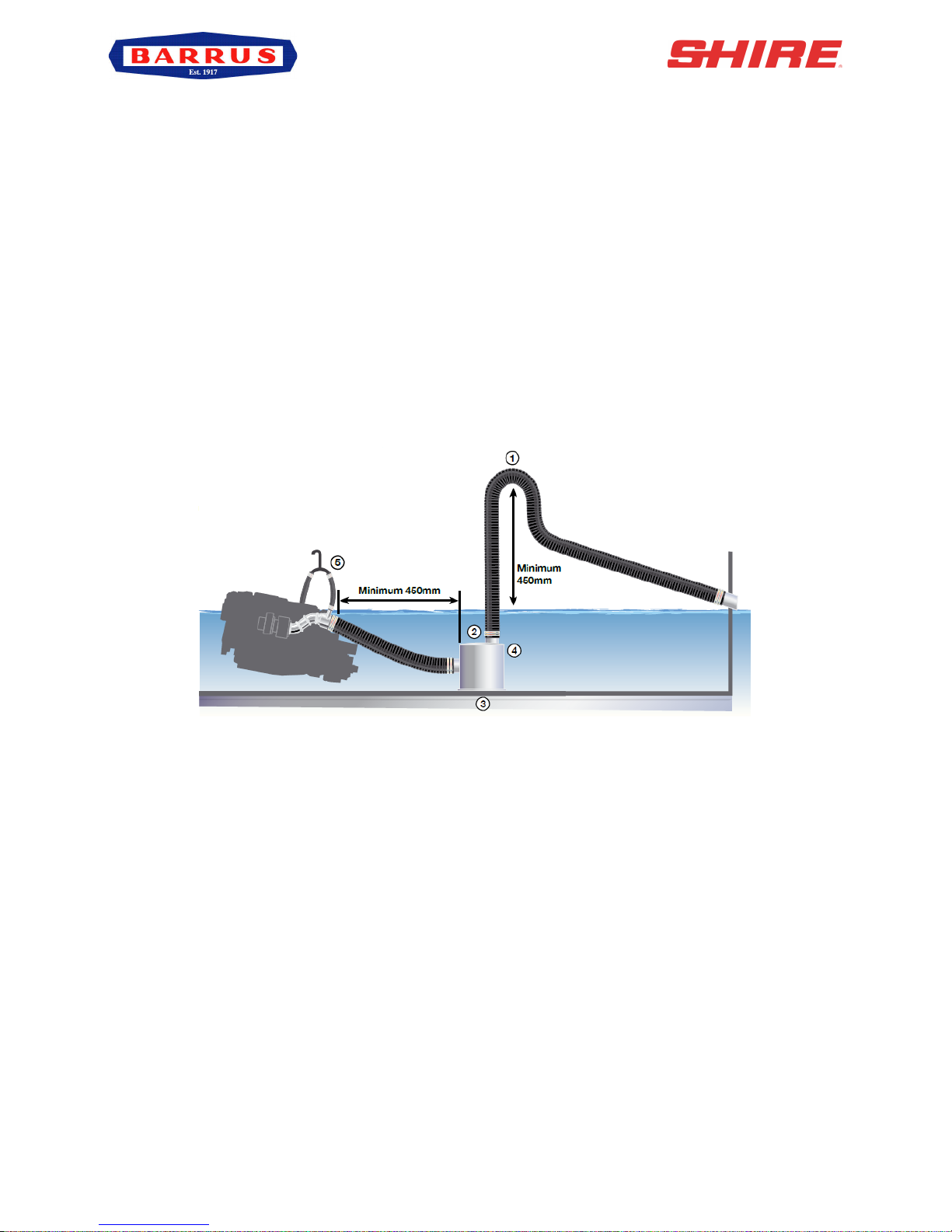
• Lift Silencer
The correct installation of the lift silencer is vital to safety, and to avoid back flooding of
the engine. Figure 13 shows how to install the lift silencer correctly (Note: Halyard (M&I)
Limited have given Barrus permission to use the diagram).
Figure 13: Correct Installation of the Lift Silencer
1. The swan neck must reach at least 450mm (18”) above the waterline, when
installed on hull centreline.
2. The top of the silencer should be at least 300mm (12”) below the water injection
point.
3. The silencer must be installed as near as possible to the centreline of the hull,
particularly where severe angles of heel are expected. The swan neck must be
450mm above heeled water line.
4. Remember that 15% of the volume of the exhaust hose may be water. The size
of the silencer selected must be such that water draining into it will fit it by no
more than one third.
5. A siphon break must be used.
The silencer may only be used in a Water Injected marine exhaust system. The overall
design of the system, and choice of components, will have a result on the back pressure in

RDG603A13 – Issue 7 – Shire 15 Manual 15_20 – CB_WB_RB
Page 23 of 55
the exhaust which is vital to the performance and life of the engine. Barrus recommend
that Halyard (M&I) Limited are used for the Lift Silencer, Siphon Break and other
components. Contact Halyard (M&I) Limited for further information.
The silencer must be drained before the boat is craned or transported and during the
winter.
There must be at least 450mm distance between the water injection point and the position
of the silencer to allow adequate cooling of the exhaust gases. Maximum temperature
during continuous operation of the silencer is limited to 85 degrees centigrade. Normally in
a well-designed system, the temperature of the silencer should be between 50-70 degrees
centigrade. Such operation will result in longer exhaust life.
Connections to the silencer should be made using suitable exhaust hose, which is type
approved by Lloyds and DNV. Do not use oil or grease to lubricate hoses when installing,
wetting the inside of the hoses with water will help them slip more easily over the silencer
spigots. A minimum of 2 hose clips must be used. Securely tighten all hose clamps, but be
careful not to overtighten.
The silencer should be positioned within 300mm of the centre line of the vessel, or to the
engine on which it is installed. This is particularly important on sailing vessels where a
substantial angle of heel can be encountered. On systems where the exhaust manifold is
near or below the water line. A siphon break should be used to prevent the water flow
continuing after the engine shut down.
In all installations the silencer should be at the lowest point if the entire exhaust system.
The top of the silencer should be at least below the exhaust manifold outlet for the best
performance. If a distance less than is allowed, the margin of safety for preventing reverse
flow of water toward the manifold will decrease.
• Siphon Breaker Fitting Instructions
1. The unit must be positioned upright, well above waterline. The height above
waterline will vary from vessel to vessel but will be between 150mm and 2
metres. Please seek guidance on this if you are unsure, or if you are not familiar
with the correct way to incorporate a siphon breaker into your particular exhaust
system.
2. The inverted “U” bend at the top must be connected to a hose draining into the
bilge, or over the side of the vessel. In no circumstances must this drain into a

RDG603A13 – Issue 7 – Shire 15 Manual 15_20 – CB_WB_RB
Page 24 of 55
sealed container, such as a bottle due to the risk of back siphoning. After fitting,
run the engine and check the unions for leaks. Check again after 5 running hours.
3. The siphon break is equally suitable for use with a marine toilet water inlet.
4. The ½” unit may also be used with 5/8” systems. The 3/4” and 1” units may only
be used with the correct hose.
• Siphon Breaker Maintenance
1. On commercial vessels achieving in excess of 150 engine hours per year, the
unit should have the small valve removed from the top and this should be
thoroughly washed in warm soapy water to remove salt encrustation.
2. On a pleasure vessel this should be done twice a year.
3. On reassembly the engine should be run and the unit checked for leaks. The
hose junctions should also be checked for leaks as part of the daily inspection
procedure for sea cocks, water pipes, oil levels, etc.
21. Hydraulic Drive Transmissions
If an engine is to have a hydraulic drive transmission attached to it, a number of points must
be observed.
Bobtail engines (i.e. Engines supplied without a marine gearbox), normally do not have a
gearbox oil cooler fitted. However if a cooler is supplied, this will only be suitable to cools a
conventional marine gearbox.
Hydraulic drive transmissions generate far more heat than a conventional marine gearbox.
Therefore the size of the oil cooler installed must be calculated by the hydraulic drive
transmission supplier: to ensure it has sufficient cooling capacity and is sized appropriately
taking into account:
• Maximum engine power.
• High ambient summer air temperature.
• Summer River/Canal/Sea temperature.
• No additional restriction to engine coolant flow is present.
Skin tanks will also need to be increased by approx. 10% to dissipate the additional heat
generated.
Oil coolers should be installed in the seawater cooling system after the engine, not before.
Coolers that are installed before the engine will invalidate the engine warranty.

RDG603A13 – Issue 7 – Shire 15 Manual 15_20 – CB_WB_RB
Page 25 of 55
22. Installation Check List
Please tick box !
Engine alignment correct, clearance all round, check propeller turns by
hand (Ensure ignition is off battery and battery master switch is off)
Anti-Vibration mounts correct height, spacers if necessary. Make sure all
nuts are tight
Exhaust system as specified
Battery leads are of correct size, tightened and start battery is charged
Check tension of alternator belts & wiring connected
Belt alignment checked and corrected if necessary
Check fuel system is connected correctly and primed
Fuel line water trap installed and water drained off
Check header tank and skin tank connections are correct way round,
constant pipework rise to header tank
Check level of coolant in header tank and correct ratio of antifreeze to
water
All air has been bled from skin tank, calorifier and pipework
Engine and gearbox oil levels are as specified
Throttle and gear cables correctly adjusted and operating smoothly
All pipework and cabling supported and not chaffing, slack to allow
movement of engine
Confirm engine control panel, gauges and warning lights are all
operational
Suitable specification of hose between seacock and seawater pump with
no restrictions is fitted
Run the engine for 20 minutes with the boat tied up and in gear (at ½
speed). Check for leaks and that all systems operate correctly
Check & Set the Engine Idle Speed to 850-875 rpm
Check for leaks
Explain/Demonstrate daily/weekly/periodic maintenance checks

RDG603A13 – Issue 7 – Shire 15 Manual 15_20 – CB_WB_RB
Page 26 of 55
SECTION 4 – Operation
1. Starting the engine for the first time
• Remove ignition key.
Explain/Demonstrate off season storage and maintenance
Installer’s signature
Installer name/company

RDG603A13 – Issue 7 – Shire 15 Manual 15_20 – CB_WB_RB
Page 27 of 55
• Ensure all oil and coolant levels are checked.
• Ensure both the engine and domestic batteries are connected. Both battery master
switches must be turned on. Failure to do so may damage the domestic alternator.
2. Starting Procedure
• Ensure the gearshift control level is set to neutral and that persons are clear of any
moving parts.
• Insert ignition key.
• For standard engines ensure the fuel stop knob is pushed into the run position.
• Turn key to on position.
• Observe warning lights (and gauges on deluxe panel).
• Listen for warning buzzer.
• The cold starter glow plug light will illuminate.
• When the glow plug light extinguishes, turn key to second position, start, and hold to
crank.
• Crank the engine for no more than 15 seconds.
• On engine start, immediately release key.
• Key will return to first position, on.
• The warning buzzer will stop and on the deluxe panel the oil pressure gauge will
show an oil pressure of 3.1-4.1 bar (45-60 psi).
• Should any warning light not go out, or if there is no reading on the oil pressure
gauge, the buzzer will continue sounding. In this case, stop the engine immediately
and check the relevant system. Note: If the charge light does not go out, briefly
increase the engine speed.
• Stop engine immediately if any abnormal noises are detected.
• Visually check the engine for oil, fuel and coolant leaks (after initial start-up and at
regular intervals). Note: The engine must be stopped and ignition key removed to
carry out this check.
3. Stopping Procedure
For Standard Engine:
• Move speed control lever to the idle position.
• Pull manual stop control knob on control panel.
• Turn ignition key to off position.
For Engine with Optional Electric Stop:
• Move speed control lever to idle position.
• Turn key to off position.

RDG603A13 – Issue 7 – Shire 15 Manual 15_20 – CB_WB_RB
Page 28 of 55
4. Refuelling
• All Shire engines run on diesel fuel. DO NOT USE BIODIESEL
• Please note that when the vessel is to be left for any period of time, the fuel tank
should be left full to eliminate the build-up of condensation and formation of water in
the fuel tank.
5. Diesel Fuel Additive
• The use of diesel fuel additive is strongly recommended on Shire engines. The
quality of the fuel available when cruising is often unknown; also the fuel may have
been in storage for long periods of time. The use of additives will ensure that your
engine fuel injection system is in top condition. This should result in many years of
smooth reliable operation without the cost and inconvenience of expensive
breakdowns due to poor quality fuel. It has also been found that improvements in
fuel consumption and start ability are an added benefit of using this product.
• Diesel fuel additive is available from your Shire dealer in a handy 375ml container
(Part Number: RDG80210219)
6. Exhaust Back Pressure
• The back pressure falls within the manufacturers recommended range when using
the exhaust system recommended for the engine.
• The maximum allowable back pressure is 0.35 Bar (4 PSI)
7. Single Lever Side Mount Operation - Optional (RDG9210055)
To engage forward or reverse gear:
• Lift the safety latch under the handle before shifting.
To rev the engine in neutral:
• Pull the lever out sideways from the main body.
• Lift the safety latch under the handle then shift.

RDG603A13 – Issue 7 – Shire 15 Manual 15_20 – CB_WB_RB
Page 29 of 55
SECTION 5 – Service Procedure
CAUTION:
REMOVE THE IGNITION KEY BEFORE WORKING IN ENGINE COMPARTMENT.
1. Daily Maintenance
• Check the oil level in the sump. Make sure it lies between the upper and lower mark
lines on the dipstick.
• For Shire 15 15/20 Canal Boat/Work Boat, check the coolant level in the water bottle.
It must be between the level indicators.
• For Shire 15 15/20 River Boat, check the level in the exhaust heat exchanger.
• Check the oil level inside the governor of the fuel injection pump. Refill it if
insufficient.
• Check for leakage of oil, water and air.
• Check the installation of the engine. Make sure all mounting bolts are tightened, as
well as other components.
2. Engine Oil and Filter Change
• Change the engine oil while the engine is still hot.
• Remove the blanking plug in the sump pump spout (6mm Allen key).
• Place a plastic tube over the spout and into a container. Operate the pump handle
to empty the sump. Note: Remember to refit the blanking plug afterwards.
• Place a drip tray under the engine to catch the small amount of oil that will escape
from the oil filter. Using the strap type oil filter removal tool supplied, slacken the
filter from the engine block in an anti-clockwise direction. Remove the tool and spin
off the filter.
• Lightly oil the new filter O ring seal and install the filter onto the engine. Spin it on in
a clockwise direction and finally tighten by hand only as firmly as you can.
• Refill the sump using the oil filler cap in the rocker cover on top of the engine.
• Oil level should be to the top mark on the dipstick.
• Run the engine for 5 minutes before checking the oil level with the dipstick and top
up if required.
• Do not exceed the maximum oil level marker as this may cause damage to the
internal components of the engine.
3. Air Filter Check and Change
• Release the three spring clips. Pull off the end cover to reveal the filter element.

RDG603A13 – Issue 7 – Shire 15 Manual 15_20 – CB_WB_RB
Page 30 of 55
The element simply pulls out.
• To fit the new element, slide the open end of the filter element into the main body.
Gently push the element until fully seated. Refit the end cover.
• The air filter is constructed from pleated paper. Inspect it closely for dust or dirt. The
air filter cannot be cleaned and must be replaced when dirty. The engine requires
clean unrestricted air to run efficiently. Failure to maintain the air filter could result in
smoke, increased fuel consumption and ultimately engine damage. Note: Only the
single outer element is used for Marine engines.
4. Gearbox Oil Change
Note: Some engines will have an optional gearbox sump pump fitted. To change the oil in
this circumstance, follow the same procedures as were outlined for changing the engine oil.
For engines without a gearbox sump pump follow the procedure below.
• Change the gearbox oil while it is still hot (Please refer to the gearbox manual for
more information).
• Place a tray beneath the gearbox that will hold at least 5 litres.
• Replace the drain plug. Ensure that the sealing washer (if used) is still in place and
in good condition before tightening. Fit a new washer if required.
• Refill the gearbox with oil to the upper mark on the dipstick (the PRM 80 only has
one mark which is the max level mark. The PRM 60 and PRM 150 have two marks,
the top one is the max level and the bottom one is the minimum level). Refer to the
PRM owner’s manual for more details. Section 6 contains details of oil specifications.
• Do not overfill the gearbox as this can damage the internal components.
Figure 14: PRM 60
Filler Plug
Dipstick

RDG603A13 – Issue 7 – Shire 15 Manual 15_20 – CB_WB_RB
Page 31 of 55
Figure 15: PRM 80
Figure 16: PRM150 Gearbox (Optional)
5. Disposal of Oil and Related Items
• Please dispose of used oil and oil filters safely with due regard for the environment
and take to your local waste oil disposal point.
• Do not allow oil or contaminated parts to enter the inland water way system.
6. Fuel Filter Drain – Shire 15 15/20
• Place a small drain bowl under the primary fuel filter / water trap.
• Loosen the drain screw located in the bottom of the fuel filter / water trap (Figure 17)
• Drain off any water.
• Once the water has been drained, retighten the drain screw.
• It is unlikely the complete fuel system will require bleeding.
• Ensure the fuel tank is full prior to bleeding the fuel system.
• Run for 5 minutes.
• Check that the drain union is tight and that there are no leaks.
• Do not over tighten the drain screw.
Note: The boat builder must have fitted an additional water trap in the fuel system. Ensure
that this is drained regularly.
Level dipstick / Filler Plug
Level dipstick / Filler Plug

RDG603A13 – Issue 7 – Shire 15 Manual 15_20 – CB_WB_RB
Page 32 of 55
Figure 17: Fuel Filter Drain Screw
7. Fuel Filter Change
• Ensure the fuel tank is at least ¾ full prior to undertaking this procedure.
• Turn off the main boat fuel supply tap. This is located on or near the fuel tank.
• Place a small drip tray under the filter body.
• Remove the fuel filter in the same way as the oil filter in Part 1 of Section 5.
• Smear a small amount of clean fuel on all of the O ring seals that are supplied with
the new filter element.
• Screw the new element back into the filter head. Tighten by hand only.
• Turn the main boat fuel supply tap back on.
• Ensure the system is correctly bled before attempting to start up.
8. Fuel System Bleeding
• Ensure the fuel tank is at least ¾ full prior to undertaking this procedure.
• Open the bleed screw on top of the engine fuel filter.
• Operate the fuel lift pump by hand or if there is an electric fuel pump, turn the ignition
keys on.
• After the fuel filter has been purged of air, close the bleed screw.
• Undo ALL the injector pipe connections.
• Crank the engine over with the starter motor. When fuel can be seen, stop cranking.
• Tighten the injector pipe connections.
• Wipe off any excess fuel.
• Crank the engine.
• The engine should now start. If it does not start, repeat the above procedure.
• Check for any leaks and clean up any spilt fuel.
9. Cooling System
Drain Screw

RDG603A13 – Issue 7 – Shire 15 Manual 15_20 – CB_WB_RB
Page 33 of 55
CAUTION:
DO NOT CHECK THE COOLANT LEVEL WHEN THE ENGINE IS HOT. REMOVE THE
IGNITION KEY BEFORE WORKING IN ENGINE COMPARTMENT.
For All Models
• To check the coolant level, ensure that the engine has been shut down for at least
half an hour.
For Canal Boats & Work Boats
• The coolant level can be checked visually and should be between the two level
marks formed on the front of the white plastic expansion tank.
For River Boats
• Remove the lid from the water cooled exhaust manifold/heat exchanger. The level
should be ½” (13mm) below the filler neck.
For All Models
• If required, top up the level with coolant (50% clean tap water and 50% ethylene
glycol based anti-freeze) through the expansion tank filler cap.
• Do not use water only to top up as this weakens the coolant mix, reducing the level
of frost protection and anti-corrosion protection of the coolant.
10. Belt Adjustment
CAUTION:
REMOVE THE IGNITION KEY BEFORE WORKING IN ENGINE COMPARTMENT.
• Depress the longest run of the drive belt to be checked. If the travel exceeds 15-
20mm using hard finger pressure, the belt needs re-tensioning.
• Loosen the upper adjuster on the alternator. Loosen the lower mounting pivot nut
and bolt. Pull out either using hand pressure, or a small plastic/wooden lever.
• Pull the alternator away from the engine to tighten the belt.
• Hold the alternator in position and retighten all the bolts

RDG603A13 – Issue 7 – Shire 15 Manual 15_20 – CB_WB_RB
Page 34 of 55
Note: If the belts are over tightened, alternator bearing failure will occur.
11. Belt Maintenance
• Do not allow oil to contact the belt. Oil attacks the construction of the belt. This
reduces the drive efficiency and ultimately cause it to fail prematurely.
• Replace the belt if it cracks or splits and as the adjustment nears the limit of travel.
Note: Some boat builders may remove one or more of the alternators during the installation
of the engine. It is essential that when the alternators are refitted that the alignment is
perfect or premature belt wear will occur.
12. Belt Replacement
CAUTION:
REMOVE THE IGNITION KEY BEFORE WORKING IN ENGINE COMPARTMENT.
• Ensure that you have the correct replacement belts before starting this procedure.
Some engines may have been fitted with non-standard optional alternators which
may not use the belt sizes listed. Make a note of these belt sizes upon delivery.
• Loosen the top adjuster bolts and the lower mounting pivot nut and bolt.
• Push the alternator towards the engine to loosen the belt.
• Remove the belt.
• Hold the belt in position over the top alternator pulley. Rotate the engine if required
by hand, to guide the new belt into the “vee”.
• Re-tension the belt as above.
13. Control Panel Maintenance
CAUTION:
REMOVE THE IGNITION KEY BEFORE WORKING IN ENGINE COMPARTMENT.
TURN BATTERY ISOLATION SWITCHES OFF.
• To replace an illumination bulb: Release the panel from its mounting. The bulbs
are accessible from the rear of the panel. Remove the wires, unscrew the nut and

RDG603A13 – Issue 7 – Shire 15 Manual 15_20 – CB_WB_RB
Page 35 of 55
pull out the bulb housing from the panel. Remove the bulb and replace. Refit bulb
housing, screw the nut back up and refit the wires.
• To replace any gauge: Release the panel from its mounting. The gauges are
accessible from the rear of the panel. Unplug the wire connectors, unscrew and pull
the gauge out of the panel. Replace the gauge and refit. Reattach the wiring
connectors.
Note: Periodically squirt a lubricant into the key switch slot when the key has been
removed. A lubricant such as WD40 – with silicon, would be suitable. Other lubricants are
available. Then with the battery master switch turned off, operate the key switch a couple
of times. This will ensure the lubricant works into the mechanism.
14. Sacrificial Anode Change
For Work Boats
• The anode is located in the “T” fitting on top of the engine at the front facing forward
(Figure 18).
Figure 18: Work Boat Anode Location
For River Boats
• The anode is located on the water cooled manifold (Figure 19).
Figure 19: River Boat Anode Location
15. Raw Water Pump Impellor Change (Work Boat & River Boat)
• The pump is located on the front of the engine.
• Remove the pump cover plate.
• Remove the pump impeller (special tools are available from chandleries to assist
with this task).
Anode
Anode

RDG603A13 – Issue 7 – Shire 15 Manual 15_20 – CB_WB_RB
Page 36 of 55
• Note: Do not lever against the front of the pulley housing as it is easily damaged.
• Inspect the pump housing and front housing for damage or wear.
• Replace the impellor.
• Replace the cover plate gasket if damaged.
• Replace any other worn components as necessary.
16. Engine Heat Exchanger Tube Stack Flushing
For Work Boats
• When the engine is cold, drain the water from the engine block. Remove the hose
from the tap and drain.
• Drain water from the heat exchanger. The drain plug is in the bottom of the heat
exchanger end cap.
• Disconnect the pipes and hoses from the engine heat exchanger.
• Remove the heat exchanger from the engine.
• Mark the position and remove the end caps from the heat exchanger. When refitting
the end caps please ensure that they are in the same orientation as they were
previously.
• Carefully remove the tube stack from the centre of the heat exchanger.
• Fully flush between the tubes to remove any dirt of scum build up.
• Inspect the tube stack and replace if damaged.
• Reassemble and refit, checking the end cap “O” rings are in good condition.
• Refill the engine with coolant as described earlier.
For River Boats
• When the engine is cold, drain the water from the engine block. Remove the plug
from the engine block by the starter motor.
• Drain water from the heat exchanger. The drain plug is in the bottom of the heat
exchanger / water cooled manifold.
• Mark the position and remove the end caps from the heat exchanger along with the
“O” rings. When refitting the end caps please ensure that they are in the same
orientation as they were previously.
• Carefully remove the tube stack from the centre of the heat exchanger.
• Fully flush between the tubes to remove any dirt of scum build up.
• Inspect the tube stack and replace if damaged.
• Clean out the manifold if required.
• Reassemble and refit, checking the end cap “O” rings are in good condition.
• Refill the engine with coolant as described earlier.

RDG603A13 – Issue 7 – Shire 15 Manual 15_20 – CB_WB_RB
Page 37 of 55
17. Winterization of Seawater Cooling System (Work Boat & River Boat)
• To prevent frost damage to the seawater cooling circuit components due to water
freezing, ensure all seawater or raw water is drained from the system.
• Alternatively, run neat antifreeze through the seawater pump inlet to protect the
system.
• Ensure that the antifreeze is drained before starting the engine during the next
season. This is to ensure that it does not get into the marine environment. Dispose
of the antifreeze correctly.
RDG603A13 – Issue 7 – Shire 15 Manual 15_20 – CB_WB_RB
Page 38 of 55
SECTION 6 – Service Schedule
1. Specifications and Capacities
Specification of Coolants and Lubricants to use:
Component
Lubricant
Engine
SAE 10W 40 API Class CD Oil
Coolant
50% Clean Water + 50% Ethylene Glycol Antifreeze
PRM 60 Gearbox
ATF (Automatic Transmission Fluid) Oil
PRM 80 Gearbox
ATF (Automatic Transmission Fluid) Oil
PRM 150 Gearbox
Engine Oil
Engine Oil Capacity (with Filter):
Engine
Capacity (Litres)
Capacity (Pints)
15
1.73 3 20
2.6
4.5
Gearbox Oil Capacity (Excluding Cooler where fitted):
Gearbox
Capacity (Litres)
Capacity (Pints)
PRM 60
0.3
0.52
PRM 80
0.57
1.0
PRM150
1.4
2.5
2. Service Intervals
Check
Change
Notes
Engine Oil & Filter
Daily (Level)
Every 150 Hours
OR 12 Months*
First change after 25 hours
Gearbox Oil
Weekly
(Level)
Every 300 Hours
OR 12 Months*
First change after 25 hours
Coolant Level
Daily (Level)
Every 24 Months
-
Diesel Fuel Filter
50 hours
Every 300 hours
OR 12 Months*
Drain water every 50 hours
OR Monthly**
Air Filter Element
150 Hours
Every 300 hours
OR 24 Months*
Sooner if required
Drive Belts
Daily
As required
Adjust as necessary
Key Switch
Lubricate
Every 150 hours
OR 12 Months*
As per instructions in Section
12 - Control Maintenance

RDG603A13 – Issue 7 – Shire 15 Manual 15_20 – CB_WB_RB
Page 39 of 55
Sea Water Pump
Impellor (WB/RB Only)
150 Hours
Every 300 hours
OR 24 Months*
Sooner if required
Sacrificial Anodes
150 Hours
Every 450 hours
OR 12 Months*
Check and change more
frequently if local conditions
require it
Main Heat Exchanger
450 Hours
Or check more frequently if
local conditions require it.
Remove & clean as per
instructions in Section 5
* Whichever occurs first.
** If large quantities of water are found in the fuel when the filter is drained, increase the
frequency of draining.

RDG603A13 – Issue 7 – Shire 15 Manual 15_20 – CB_WB_RB
Page 40 of 55
SECTION 7 – Wiring Diagrams
1. Engine Wiring Diagram Shire 15 15/20

RDG603A13 – Issue 7 – Shire 15 Manual 15_20 – CB_WB_RB
Page 41 of 55
2. Standard Control Panel Wiring Diagram

RDG603A13 – Issue 7 – Shire 15 Manual 15_20 – CB_WB_RB
Page 42 of 55
3. Deluxe Control Panel Wiring Diagram (Additional Option – SS1551)
RDG603A13 – Issue 7 – Shire 15 Manual 15_20 – CB_WB_RB
Page 43 of 55
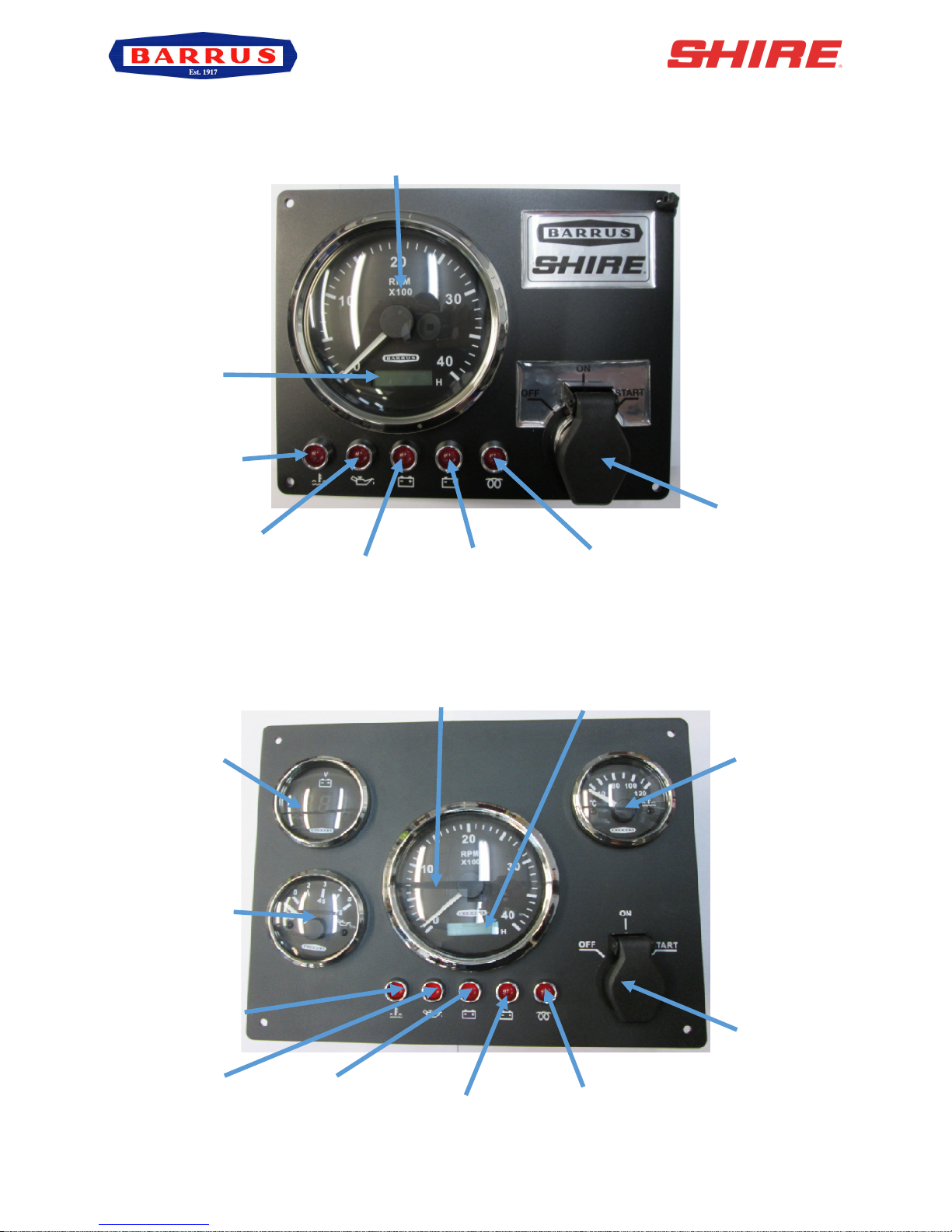
4. RDG20710110 – Standard Control Panel
5. RDG20710111 – Deluxe Control Panel (Additional Option – SS1551)
Tachometer
Hour Meter
Water
Temperature
Warning Light
Oil Pressure
Warning Light
50A Alternator
Charge Light
Glow Plug Light
Key Flap &
Ignition Switch
50A Alternator
Voltage Output
Tachometer
Key Flap &
Ignition Switch
Glow Plug Light
50A Alternator
Charge Light
Oil Pressure
Warning Light
Water
Temperature
Warning Light
Oil Pressure
Gauge
Water
Temperature
Gauge
Hour Meter
Optional Additional
70 amp Alternator
Optional Additional
70 amp Alternator

RDG603A13 – Issue 7 – Shire 15 Manual 15_20 – CB_WB_RB
Page 44 of 55
6. Overall Dimensions of the Control Panels
RDG20710110 - Standard Control Panel (All Dimensions are in mm)
RDG20710111 – Deluxe Control Panel (All Dimensions are in mm)

RDG603A13 – Issue 7 – Shire 15 Manual 15_20 – CB_WB_RB
Page 45 of 55
SECTION 8 – Technical Data
Model
Shire 15 15
Shire 15 20
Type
In Line, Water Cooled, 4 Stroke
In Line, Water Cooled, 4 Stroke
Combustion Chamber
Swirl Chamber
Swirl Chamber
Type of Cylinder Liner
Dry
Dry
Number of Cylinders 2 3
Bore (mm)
78
78
Stroke (mm)
78.4
78.4
Displacement (L)
0.749
1.123
Compression Ratio
22.1
22:1
Firing Order
1-2
1-2-3
Rated Output/Speed (kw/r/min)
11/3000
15/3000
Max Torque/Speed (Nm/r/min)
37.4/1820
59.2/1960
Min Fuel Consumption (g/kw.h)
≤ 272
≤ 280
Lube Oil Consumption (g/kw.h)
0.272
0.272
Direction of Rotation of
Crankshaft
Counter Clockwise (View from
Flywheel End)
Counter Clockwise (View from
Flywheel End)
Lubrication System
Combination of Pressure and
Splash
Combination of Pressure and
Splash
Cooling System
Forced Water Cooled
Forced Water Cooled
Valve Timing
Intake Valve opens
8° Before T.D.C
Intake Valve closes
42° After B.D.C
Exhaust Valve opens
42° Before B.D.C
Exhaust Valve closes
14° After T.D.C
Valve Clearance (cold)
Intake Valve (mm)
0.15~0.20
Exhaust Valve (mm)
0.15~0.20
Max Speed (r/min)
≤ 3200
Idle Speed (r/min)
850~875
Fuel Injection Timing (°)
14~17°
Injection Pressure (MPa / PSI)
16~17 / 2320~2465
Max Exhaust Temperature (°C)
≤ 550
Max Oil Temperature (°C)
≤ 105
Normal Outlet Water Temperature (°C)
80~90
Oil Pressure
At Rated Speed (kPa) / (PSI)
310~413 / 45~60
At Idle Speed (kPa) / (PSI)
≥ 50 / ≥ 7.25

RDG603A13 – Issue 7 – Shire 15 Manual 15_20 – CB_WB_RB
Page 46 of 55
Fuel Injector
Model
Axis Needle Type
Fuel Injection Pump
Type
Plunger Type
Plunger Diameter (mm)
6.0
Lube Oil Pump
Type
Inner and Outer Rotors
Cooling Water Pump
Type
Centrifugal Type
Speed (r/min)
4000
Flow (L/min)
100 Lift (mW.G)
6
Starting Motor
Type
QDY1257A
Power (kW)
1.2 Voltage (V)
12
Alternator
Output (A)
50 Voltage (V)
14
Recommended Start Battery Size
Capacity (A.h)
≥ 65
Voltage (V)
12
Torques for Main Bolts
Cylinder Head bolts (Nm)
80~90
Main Bearing Cap (Nm)
50~60
Connecting Rod Bolts (Nm)
50~55
Flywheel Bolts (Nm)
80~90
Main Crank Pulley Bolt (Nm)
110~130
Main Bearing Seat Bolts (Nm)
60~70
Servicing Period
Fuel Injector Test/Replace
500 Hours
Engine Valve Clearances
500 Hours
RDG603A13 – Issue 7 – Shire 15 Manual 15_20 – CB_WB_RB
Page 47 of 55
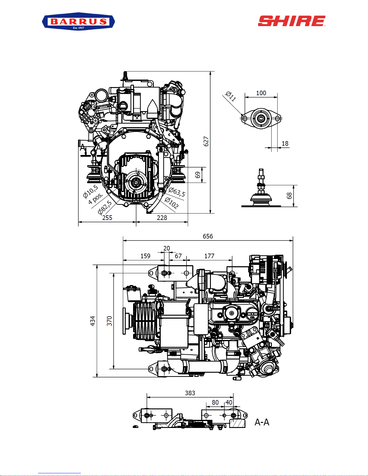
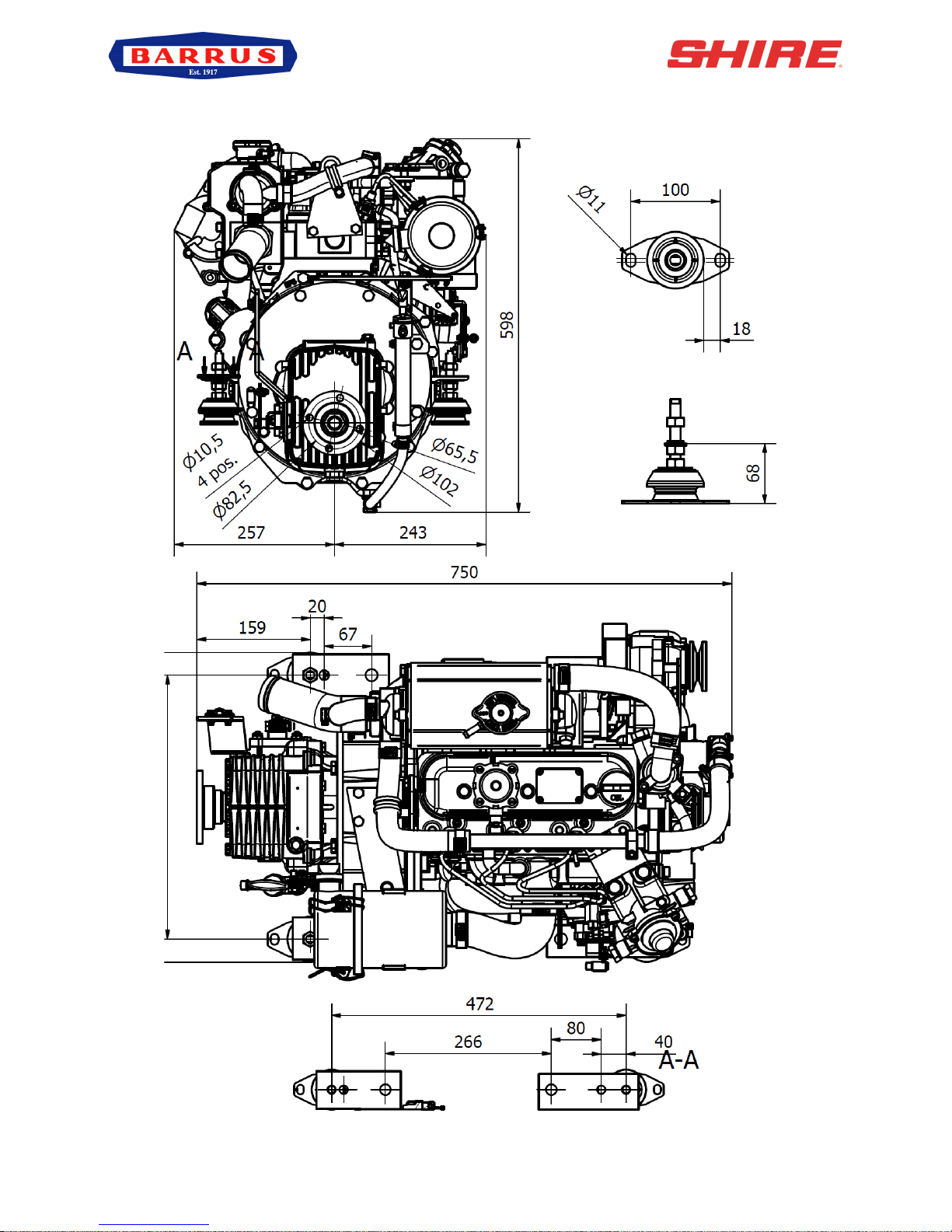
SECTION 9 – General Arrangement Drawings
1. General Arrangement Shire 15 15 Canal Boat

RDG603A13 – Issue 7 – Shire 15 Manual 15_20 – CB_WB_RB
Page 48 of 55
2. General Arrangement Shire 15 15 River Boat

RDG603A13 – Issue 7 – Shire 15 Manual 15_20 – CB_WB_RB
Page 49 of 55
3. General Arrangement Shire 15 20 Canal Boat
RDG603A13 – Issue 7 – Shire 15 Manual 15_20 – CB_WB_RB
Page 50 of 55
4. General Arrangement Shire 15 20 River Boat

RDG603A13 – Issue 7 – Shire 15 Manual 15_20 – CB_WB_RB
Page 51 of 55
SECTION 10 – Dealer List
Area
Company
Telephone
Email
BERKSHIRE
Bluenine Marine
01189 406482
bluenine@marine7957.fsnet.co.uk
Aquatec Marine
07880793686
sales@aquatecmarine.com
Driveline Marine
0118 942 3877
tam@drivelinemarine.com
CHESHIRE
Nantwich Canal Centre
01270 625122
info@nantwichcc.com
CORNWALL
Black Dog Marine
01503 265898
blackdogmarine@googlemail.com
Cellar Marine
01326 280214
john@cellarmarine.com
G B Smith & Son
01208 862815
info@gbsmithandson.co.uk
CUMBRIA
Windermere Aquatic Ltd
01539 442121
service@aquaticboatcentres.com
DERBYSHIRE
Midland Canal Centre
01283 701933
info@mccboats.co.uk
DEVON
Sleeman & Hawkin Ltd
01626 778266
keith@sleeman-hawkin.co.uk
Tonto Marine
01803 844399
enquiries@tontomarine.co.uk
Mobile Marine
01297 631821
mobilemarine@btconnect.com
Darthaven Marina
01803 752242
admin@darthaven.co.uk
ESSEX
French Marine Motors Ltd
01206 305233
01255 850303
info@frenchmarine.com
HAMPSHIRE
Marine Power Ltd
0238 0403918
info@marine-power.co.uk
HEREFORDSHIRE
Starline Marine
01684 593443
narrowboats@starline.demon.co.uk
HERTFORDSHIRE
P & S Marine
01923 248372
pandsmarinellp@gmail.com
LANCASHIRE
British Waterways
01257 481054
@emmalene.foster@bwml.co.uk
LEICESTERSHIRE
Foxton Boat Services Ltd
01162 792285
tony@foxton-boats.freeserve.co.uk
LONDON
De La Hunty Marine
02089 792121
delahuntymarine@btinternet.com
NORFOLK
French Marine Motors Ltd
01603 722079
info@frenchmarine.com
NORTHAMPTON
Grand Junction Boat Co.
01604 858043
grandjunco@talk21.com
NOTTINGHAM
Farndon Marina
01636 705483
info@farndonmarina.co.uk
OXFORDSHIRE
Service Engine UK
01993 835157
info@serviceenginesuk.co.uk
SHROPSHIRE
Maestermyn (Marine) Ltd
01691 662424
enquiries@maestermyn.co.uk
STAFFORDSHIRE
JD Boat Services Ltd
01902 791811
jdboats@btinternet.com
Stone Boatbuilding Company
01785 812688
sales@stonebuilding.co.uk
Streethay Warf
01543 414770
pat@streethaywarf.freeserve.co.uk
WARWICKSHIRE
Barry Hawkins Narrowboats
01827 711762
boats@hawkinsyard.freeserve.co.uk

RDG603A13 – Issue 7 – Shire 15 Manual 15_20 – CB_WB_RB
Page 52 of 55
Onboard Energy
02476 393333
sales@onboardenergy.com
Springwood Haven Leisure Ltd
0845 4566572
enquiries@springwoodhaven.co.uk
Valley Boat Services Ltd
07990528123
enquiries@valleycruises.co.uk
WEST MIDLANDS
Stephen Goldsbrough Boats
01564 778210
andy@sgboats.com
WILTSHIRE
Foxhangers Marine
01380 828795
info@foxhangers.co.uk
WORCESTERSHIRE
J L Pinder & Son
01527 876438
sales@jlpinderandsons.co.uk
Starline Narrowboats
01684 874774
narrowboats@starline.demon.co.uk
YORKSHIRE
Rodley Boat Centre
01132 576132
John.snowdenz@ntlworld.com
MONMOUTHSHIRE
Castle Narrowboats
01873 830001
castlenarrowboats@btinternet.com
EIRE
Dun Laoghaire Marine Services
00353 12104776
info@dlms.ie
O’Sullivans Marine
003536 67124524
brian@sulliansmarine.com

RDG603A13 – Issue 7 – Shire 15 Manual 15_20 – CB_WB_RB
Page 53 of 55
SECTION 11 – Shire Service Parts
Model
15/20 CB
15/20 WB
15/20 RB
Fuel Filter
RDG906A3
RDG906A3
RDG906A3
50A Alt Belt
GB/T12732-2008
GB/T12732-2008
GB/T12732-2008
70A Alt Belt (Single
Alt Engine)
GB/T12732-2008
GB/T12732-2008
GB/T12732-2008
70A Alt Belt (Twin
Alt Engine)
- - -
Air Filter Element
3011-T3-0004
3011-T3-0004
3011-T3-0004
Oil Filter
119305-35151
119305-35151
119305-35151
Sea Water Pump
Impeller
N/A
RDG010A3
RDG010A3
Sea Water Pump
N/A
RDG907A4
RDG907A4
Zinc Anti Corrosive
Anode
N/A
119574-44150
80162
Zinc Sticker
N/A
124220-09340
124220-09340
Fuses:
The electrical system is fitted with three or four blade type fuses:
a) Control Panel supply: 15amp (RDG3245)
b) Engine start control system: 15amp (RDG3245)
c) Engine stop control system: 40amp (RDG3246)
d) Glow Plug Fuse: 40amp (RDG3246)
Relays:
e) Cold Start Relay: (RDG1396)
f) Starter Relay: (RDG5279)

RDG603A13 – Issue 7 – Shire 15 Manual 15_20 – CB_WB_RB
Page 54 of 55
Engine Oil:
Engine Oil is available from your Shire Dealer in convenient 5 litre containers (Part Number
RDG6110).
Diesel Fuel Additive:
Diesel fuel additive is available from your Shire Dealer in a handy 375ml container (Part No
RDG80210219).
SECTION 12 – Shire Service Record Card
c) 40A
b) 15A
d) 40A
f) Starter Relay
e) Cold Start Relay
a) 15A

RDG603A13 – Issue 7 – Shire 15 Manual 15_20 – CB_WB_RB
Page 55 of 55
SERVICE RECORD CARD
Model: ………………………………………………………………………
Engine No: ………………………………………………………………..
Carried out by E.P.Barrus
Print Name:
Actual Hours:
Signed:
Boat Builder Stamp:
Commission of Boat and Hand Over to Customer.
(Refer to the Installation Check List Page in this
Manual).
Date:
Signed:
Dealer Stamp:
Actual Hours:
Signed:
Dealer Stamp:
Actual Hours:
Signed:
Dealer Stamp:
Actual Hours:
Signed:
Dealer Stamp:
Actual Hours:
Signed:
Dealer Stamp:
Actual Hours:
Signed:
Dealer Stamp:
Actual Hours:
Signed:
Please refer to Owner’s Manual for service intervals
PDI
1st
2nd
3rd
4th
5th
6th
 Loading...