

Barrett Communication BC407521, BC407520 User Manual
Operating and Installation
Manual
Barrett 4075 Linear Amplier
BCM407500/10
© Barrett Communications
Head Ofce:
Barrett Communications Pty Ltd
47 Discovery Drive, Bibra Lake, WA 6163 Australia
Tel: +61 8 9434 1700 Fax: +61 8 9418 6757
Email: information@barrettcommunications.com.au
www.barrettcommunications.com.au

BARRETT 4075 LINEAR AMPLIFIER - OPERATING & INSTALLATION MANUAL
Contents
Introduction .............................................................................................................. 4
Terms and Abbreviations ...................................................................................................4
Exploring the 4075 Linear Amplier ........................................................................ 5
Front Panel ......................................................................................................................... 5
Keypad ...............................................................................................................6
Rear Panel .......................................................................................................................... 6
Switching the Linear Amplier On / Off ................................................................... 8
Switching the Linear Amplier On .................................................................................... 8
Switching the Linear Amplier Off ...................................................................................8
Error States ............................................................................................................... 9
Display .................................................................................................................... 10
Main Menu ....................................................................................................................... 10
Conguration Menu ......................................................................................................... 10
1 - Exciter .........................................................................................................11
2 - ATU .............................................................................................................11
3 - AUX .............................................................................................................11
4 - Optical ........................................................................................................11
5 - Network ......................................................................................................11
6 - Language ....................................................................................................12
7 - Other ..........................................................................................................12
8 - Factory Reset ...............................................................................................13
Diagnostics Menu ............................................................................................................ 14
1 - Clear Critical Error .......................................................................................16
2 - Filter Control Menu .....................................................................................16
3 - Attenuation Control ....................................................................................17
4 - Power Relay Control ....................................................................................18
5 - Power Supply Control .................................................................................18
6 - Pallet 0 Control ...........................................................................................19
7 - Pallet 1 Control ...........................................................................................20
8 - Fan Control Menu .......................................................................................21
9 - Pump Control ..............................................................................................22
10 - Bypass Lock On Control .............................................................................22
2

BARRETT 4075 LINEAR AMPLIFIER - OPERATING & INSTALLATION MANUAL
Installation and Setup ............................................................................................ 23
Safety ............................................................................................................................... 23
Getting Started ................................................................................................................ 23
Mains Connection ............................................................................................................ 23
Ground (Earth) System .................................................................................................... 25
Land System Grounding ...................................................................................25
Marine System Grounding ................................................................................26
Corrosion ....................................................................................................26
Antenna Connection ........................................................................................................ 27
Fitting the Linear Amplier ............................................................................................. 27
4050 Transceiver Setup....................................................................................................27
4075 System Connections ................................................................................................ 28
4075 Connections - Rear View .........................................................................29
System Description .......................................................................................................... 31
In Standby (Receive) Mode (No PTT) .................................................................31
In Transmit Mode (PTT Active) ..........................................................................31
Operation Settings .................................................................................................. 32
Factory Settings ............................................................................................................... 32
System Settings ............................................................................................................... 32
Maintenance .................................................................................................................... 33
4075 - Specications ............................................................................................... 34
General ............................................................................................................................. 34
Mechanical ....................................................................................................................... 35
Environmental ................................................................................................................. 35
Controls and Indicators ................................................................................................... 35
Connectors (Front) ........................................................................................................... 36
Connectors (Rear) ............................................................................................................ 36
Protection .........................................................................................................................36
Limited 3 Year Warranty Statement ....................................................................... 37
Warranty Registration and Technical Support ....................................................... 38
Warranty Registration Contact Details ...........................................................................39
3

BARRETT 4075 LINEAR AMPLIFIER - OPERATING & INSTALLATION MANUAL
Introduction
The Barrett 4075 is a solid-state linear amplier operating from 1.6 MHz to
30 MHz. It can be supplied with a power output level of either 500 watts or
1000 watts.
Extensive self-test, system monitoring, and protection circuits are provided,
with status and tuning information being displayed on a large OLED display.
The exciter for the 4075 linear amplier is a Barrett 4050 Transceiver set
to “4075 Linear Amplier” as the antenna type, where its power output is
reduced to a maximum of 30 W, and 40 W above 20 MHz. The ALC voltage
for the exciter is derived at the Linear Amplier’s output, and is passed to the
exciter via the Breakout Box.
The Barrett 4075 Power Supply Unit provides the +48 volts required to power
the amplier.
Terms and Abbreviations
Term / Abbreviation Denition
BoB Breakout Box
CW Continuous Wave (used for Morse code)
dB Decibels
dBc Decibels relative to the carrier - is the power ratio of a
signal to a carrier signal, expressed in decibels.
dBm Power ratio in decibels (dB) of the measured power
referenced to one milliwatt (mW).
LPF Low Pass Filter
OLED Organic Light Emitting Diode
PEP Peak Envelope Power
PTT Press-To-Talk button
Selcall Selective Calls
SSB Single Sideband (a transmission format)
USB Universal Serial Bus
VSWR Voltage Standing Wave Ration
4
BARRETT 4075 LINEAR AMPLIFIER - OPERATING & INSTALLATION MANUAL
Exploring the 4075 Linear Amplier
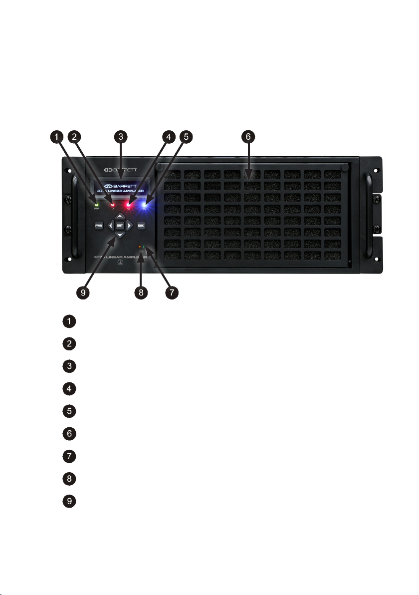
Front Panel
PWR LED illuminates green when the unit is powered on.
TX LED illuminates amber when the unit is transmitting (PTT on)
OLED screen
FLT LED illuminates red when the unit identies a fault
LOG LED illuminates blue when logging the fault history
Grill and lter for the fans
LEDs to indicate transmit (amber) and receive (green)
USB socket for programming and diagnostics
Keypad
5
BARRETT 4075 LINEAR AMPLIFIER - OPERATING & INSTALLATION MANUAL
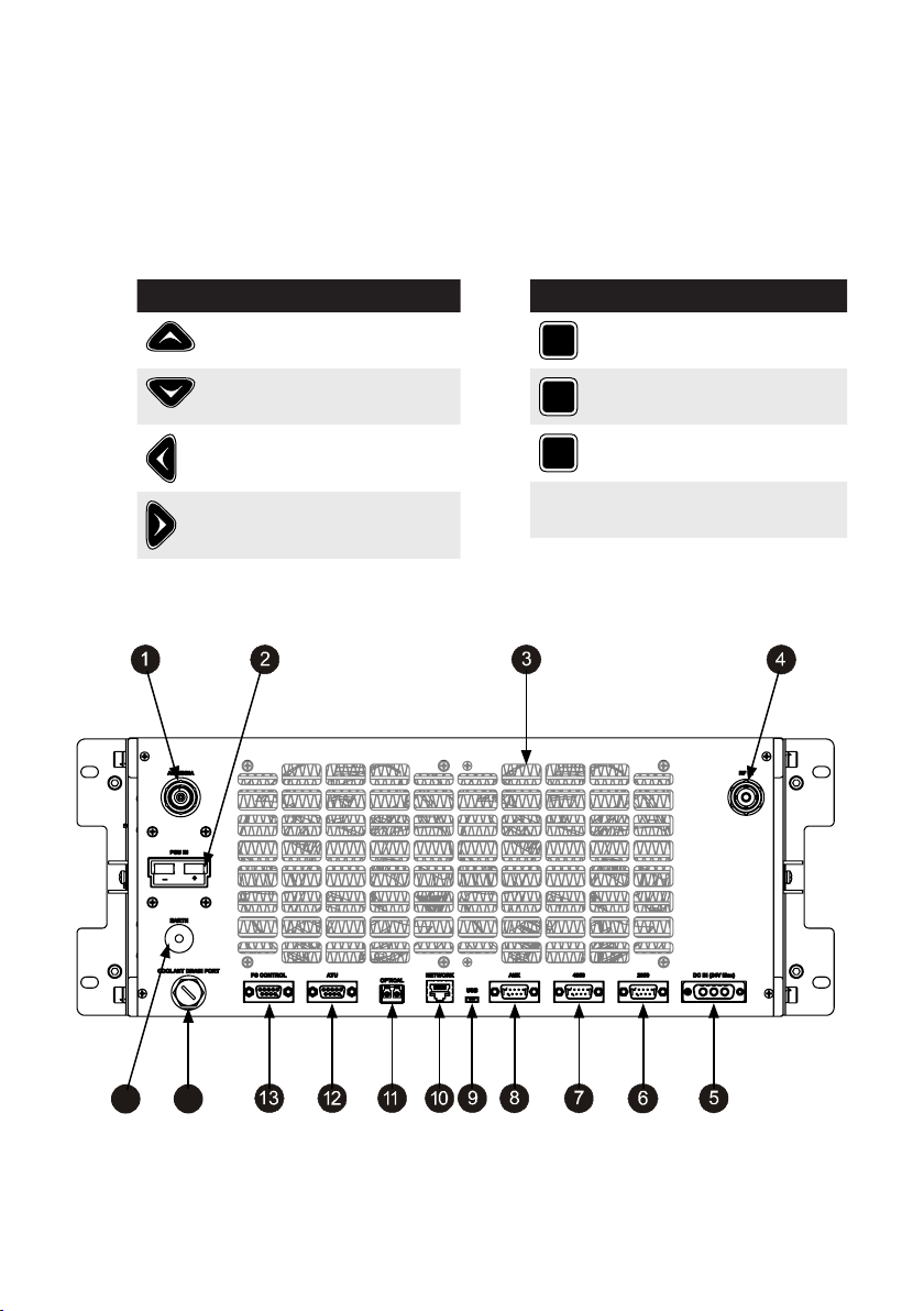
Keypad
There are seven keys on the keypad. Some keys have multiple functions
assigned to them depending on when the key is pressed and for how long the
key is pressed. Key functions are listed below followed by a description of their
functions.
Key Function
Rear Panel
Channel Up /
Scroll up
Channel Down /
Scroll down
Scroll left
Scroll right
Key Function
ENT
PWR
ESC
Enter /
Set a menu item
On / Off button
Escape /
Back one step
15
14
6

BARRETT 4075 LINEAR AMPLIFIER - OPERATING & INSTALLATION MANUAL
RF Out
48 V for Amplier
Cooling fan /grill
RF In
12 V Power Supply from 4022
2050 interface
4050 Breakout Box Interface
Auxiliary input. Used if other equipment is far away. Alarms etc
USB Interface. Used for programming and diagnostics
Ethernet network interface
Optic Fibre
ATU Interface
14
15
Control connector for Power Supply
Drain Plug
Earth connection
7
BARRETT 4075 LINEAR AMPLIFIER - OPERATING & INSTALLATION MANUAL
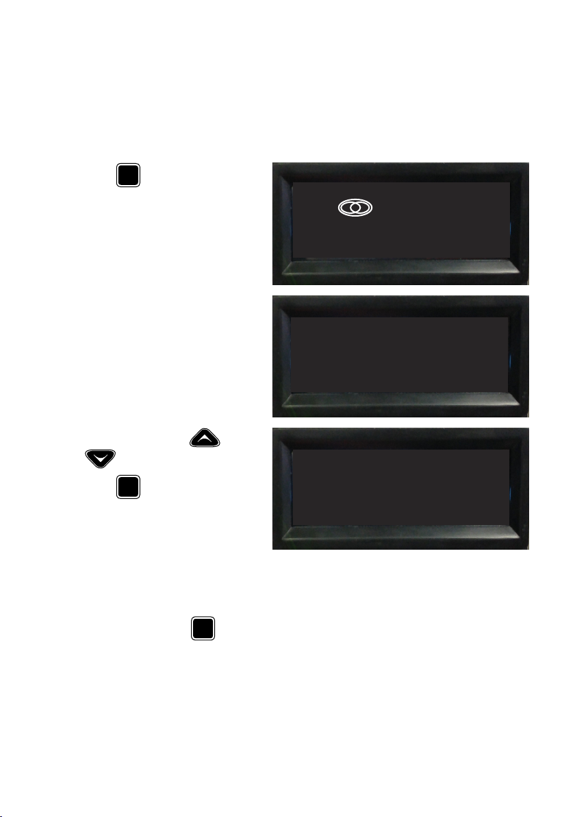
Switching the Linear Amplier On / Off
Switching the Linear Amplier On
PWR
Press
on.
The Barrett splash screen displays.
After two seconds the default
screen displays showing various
values.
to switch the unit
BARRETT
4075 LINEAR AMPLIFIER
Current: 1.19 A
Voltage: 49 V
Last VSWR: 0.00
Use the scroll keys and
to display more values.
ESC
Press
Menu.
to display the Main
Freq: 0.00 Cur0: 1.12 A
Band: 7 Cur1: 0.12 A
Out PWR: 0 W Pal0T N/A
ATTEN: 10 dB Pal1T: 32.2°C
Switching the Linear Amplier Off
Momentarily press
seconds to switch the unit off.
PWR
for ve
8

BARRETT 4075 LINEAR AMPLIFIER - OPERATING & INSTALLATION MANUAL
Error States
There are three types of error states that may be encountered during operation. These are:
Warning
The following message displays
accompanied by an audible
alarm and a ashing red LED.
This ashing message will con-
tinue until the fault condition
clears. No user intervention is
required.
Error
The following message displays
accompanied by an audible
alarm and a ashing red LED.
This ashing message will con-
tinue until the fault condition
clears or a key is pressed on the
keypad. The LED will continue
to ash but the navigational
keys will now be operable.
Critical Error
The following message displays
accompanied by an audible
alarm and a ashing red LED.
The critical error will cause the
Linear Amplier to shut down.
However, the message and LED
will continue to ash until the
Escape key is pressed.
If the critical error is cleared,
select Yes to continue.
See page 16 for further
information.
WARNING
ERROR
CRITICAL ERROR
Hit ESC to continue
Clear Error?
Conrm Update? YES NO
ERROR!
ERROR!
ERROR!
YES
9
BARRETT 4075 LINEAR AMPLIFIER - OPERATING & INSTALLATION MANUAL
Display
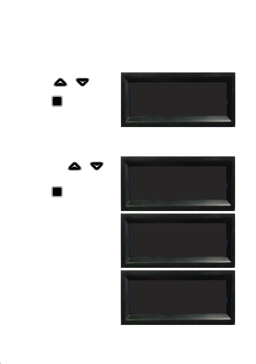
Main Menu
From the Main Menu, Press
either or to move
the selection up or down.
ENT
Press
Conguration Menu or Diagnostics Menu.
Conguration Menu
From the Conguration Menu,
press either or
to move the selection up or
down.
Press
quired menu.
to select either the
ENT
to select the re-
MAIN MENU
1 - Conguration Menu
2 - Diagnostics Menu
> LINEAR CONFIG MENU
1 - Exciter
2 - ATU
3 - AUX
< > LINEAR CONFIG MENU
4 - Optical
5 - Network
6 - Language
< LINEAR CONFIG MENU
7 - Other
8 - Factory Reset
10

BARRETT 4075 LINEAR AMPLIFIER - OPERATING & INSTALLATION MANUAL
1 - Exciter
Use this option to select which
exciter to use with the 4075
Linear Amplier.
Alternative custom exciters
(programmable) can be used.
Select Exciter from the Conguration Menu to display the
following.
> Exciter MENU
1 - Set 4050
2 - Set 2050
3 - Set Custom 1
Press or to move
the selection up or down.
ENT
Press
to set the selection.
2 - ATU
N/A. Press
ESC
3 - AUX
N/A. Press
ESC
4 - Optical
N/A. Press
ESC
5 - Network
< Exciter MENU
4 - Set Custom 2
5 - Set Custom 3
to return to the previous menu.
to return to the previous menu.
to return to the previous menu.
N/A. Press
ESC
to return to the previous menu.
11
BARRETT 4075 LINEAR AMPLIFIER - OPERATING & INSTALLATION MANUAL
6 - Language
N/A. Press
ESC
to return to the previous menu.
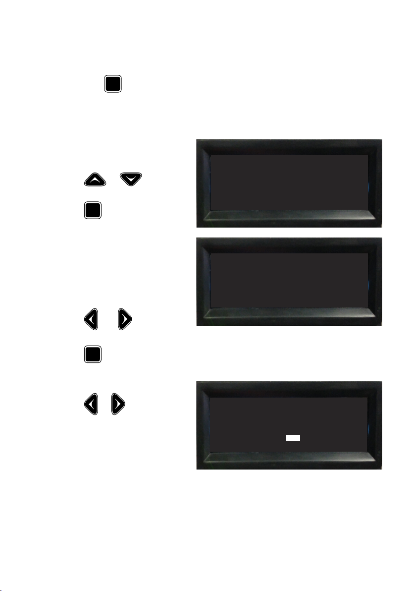
7 - Other
Select Other from the Conguration Menu to display the
following.
Press or to move
the selection up or down.
ENT
Press
ed menu.
Buzzer Control
This option enables or disables
the audio alarms.
Select Buzzer Control from
the Other Menu to display the
following.
Press and to toggle the
selection on or off.
Press
mation screen.
A conrmation screen displays.
to display the select-
ENT
to display the Conr-
> Other
1 - Buzzer Control
2 - Blocking Region
Buzzer Control ON/OFF ON
Press or to toggle the
selection Yes or No to conrm
and return to the Other Screen.
Conrm Update? YES NO
12
YES
 Loading...