

Page 1

Highland Precision
HP18 & HP24 Slab Saw
Owner’s Manual and Operating Instructions
Revision 113 07. 2 0 13
Manual Part No. 164269
Caution: Read all safety and operating
instructions before using this equipment.
This manual MUST accompany the
equipment at all times.
Barranca Diamond Products, Inc.
1315 Storm Parkway
Torrance, CA 90501
Toll-Free: (800) 630-7682
Phone: (310) 523-5867
Fax: (310) 257-3063
www.barrancadiamond.com
Page 2

TABLE OF CONTENTS
Thank you for selecting the Barranca Diamond Highland Precision Slab Saw. We are certain that you will
be pleased with your purchase. Barranca Diamond takes pride in producing top quality products for hobbyists and commercial lapidary users throughout the world. This product is manufactured in the United
States.
This owner’s manual contains information necessary to operate and maintain your Highland Precision
Slab Saw safely and correctly. Operated correctly, your Highland Precision Slab Saw should provide you
with years of service. Please take the time to familiarize yourself with the Highland Precision Slab Saw
by reading and reviewing this manual.
If you should have questions concerning your Highland Precision Slab Saw, please call Barranca
Diamond at (310) 523-5867 or Toll Free (800) 630-7682.
TABLE OF CONTENTS
SAFETY
Safety Precautions 3-5
California Proposition 65 Warning 6
Electrical Requirements 7-8
PRODUCT SPECIFICATIONS 9-10
SETUP
Unpacking & Assembly 11
Contents 11
Transport 11
OPERATION AND ADJUSTMENT
Pre-start Inspection 12
Startup 12-13
Adjustment & Operation 14-16
MAINTENANCE AND TROUBLESHOOTING
Maintenance Following Use 17
General Maintenance 18
Monthly Maintenance 18-19
Troubleshooting 20
EXPLODED VIEW & PARTS LIST
HP18 Explored View & Parts List 22-25
HP18 Vise Assembly & Parts List 26-27
HP24 Explored View & Parts List 28-31
HP24 Vise Assembly & Parts List 32-33
WARRANTY, RETURN, & CUSTOMER SERVICE
Warranty 34-35
Return & Customer Service 36
2
Page 3

HP18 & HP24 SAFETY
SAFETY PRECAUTIONS
Read and follow all safety, operating and maintenance instructions. Failure to read and follow
these instructions could result in injury or death to you or others. Failure to read and follow these
instructions could also result in damage and/or reduced equipment life. In order to prevent injury, the
following safety precautions should be followed at all times!
READ OWNER'S MANUAL BEFORE USE
Before using this equipment, ensure that the person operating this machine has read and
understands all of the instructions in the manual. Precaution is the best insurance against accidents.
Read and understand all safety precautions, messages, warnings and hazard symbols. You are
responsible for your own safety.
ALWAYS USE SAFETY GLASSES
Safety glasses should always be worn when working around power tools. In addition, a face, dust
mask or respirator should be worn if a cutting operation is dusty. Everyday eyeglasses only have
impact resistant lenses and may not prevent eye injury - they are NOT safety glasses.
USE PROPER APPAREL
Do not wear loose clothing, gloves, neckties, rings, bracelets or other jewelry that may be caught in
moving parts. Non-slip footwear is recommended. Wear protective hair covering to contain long hair.
Hand protection (plastic gloves) and a shop bib are recommended during sawing to prevent stains to
clothing. Avoid prolonged exposure of skin to the sawing lubricant and wash skin immediately after
contact. Do not touch the work material until the motor is off and the machine has come to a complete
stop.
ALWAYS USE HEARING PROTECTION
To reduce the possibility of hearing loss, always use hearing protection when operating power
equipment.
KEEP GUARDS IN PLACE
In order to prevent injury, never operate the saw without the guards in place!
REMOVE ADJUSTING KEYS AND WRENCHES
Form a habit of checking to see that keys and adjusting wrenches are removed from the power tool
before
it is turned on.
ELECTRICAL SHOCK
Never touch electrical wires or motor components while the motor is running. Exposed, frayed or worn
electrical wiring and plugs can be sources of electrical shock that could cause severe injury or burns.
DISCONNECT TOOLS
Power tools should always be disconnected before servicing or when changing accessories, such as
blades, bits, cutters and the like.
3
Page 4

HP18 & HP24 SAFETY
REDUCE THE RISK OF UNINTENTIONAL STARTS
Make sure the ON/OFF switch is in the OFF position before plugging in a power tool.
ROTATING OR MOVING PARTS
Keep hands, feet, hair, and clothing away from all moving parts to prevent injury. Never operate the
engine with covers, shrouds or guards removed.
MAINTAIN TOOLS WITH CARE
Keep tools clean for the best and safest performance. Always follow maintenance instructions for
lubricating and when changing accessories.
KEEP WORK AREA CLEAN
Cluttered work areas and benches invite accidents.
DO NOT USE IN DANGEROUS OR HAZARDOUS ENVIRONMENTS
Do not operate equipment in dangerous or hazardous environments. Do not use power tools in damp
or wet locations nor expose them to rain. Always keep the work area well lighted. Always work in a
well ventilated area.
KEEP CHILDREN AWAY
All visitors and children should be kept a safe distance from the work area. Keep power cords
disconnected when tool is not in use.
MAKE THE WORKSHOP KID-PROOF
Make the workshops kid-proof by using padlocks, master switches and by disconnecting all power
cords.
USE THE RIGHT TOOL
Do not force a tool or an attachment to do a job that it was not designed to do.
SECURE WORK
Clamps or a vise should be used to hold work whenever practical. Keeping your hands free to operate
a power tool is safer.
DO NOT FORCE THE TOOL
A power tool will do a better job and operate more safely at the feed rate for which it was designed.
USE THE RIGHT TOOL TO SERVICE THE SAW
Do not force a tool or an attachment when servicing or operating the Highland Precision Slab Saw.
Use the correct tools for service or adjustments.
DO NOT OVERREACH
Keep proper footing and balance at all times by not overreaching.
DO NOT OPERATE A TOOL WHEN TIRED
When tired, take a break and relax.
4
Page 5

HP18 & HP24 SAFETY
DIRECTION OF FEED
Always feed work into a blade or cutter in the direction shown in this manual. All blades, grinding
wheels or polishing belts should always be installed such that rotation is in the direction of the arrow
imprinted on the blade, wheel or belt.
ONLY OPERATE AT THE PROPER SPEED
Severe personal injury and damage to the motor or equipment can result if operated at speeds above
maximum.
NEVER LEAVE A TOOL RUNNING UNATTENDED – TURN POWER OFF
Do not leave a tool until it comes to a complete stop. Always turn the tool off, and disconnect the
power cord to its source, when leaving the work area or when work is finished. Do not leave extension
cords attached to the power cord or power receptacle (wall outlet) when leaving the work area.
CHECK FOR DAMAGED OR WORN PARTS
Before using a power tool, check for damaged parts. A guard or any other part that is damaged
should be carefully checked to determine if it would operate properly and perform its intended
function. Always check moving parts for proper alignment or binding. Check for broken parts and
mountings and all other conditions that may affect the operation of the power tool. A guard, or any
damaged part, should be properly repaired or replaced.
USE RECOMMENDED ACCESSORIES AND PARTS
Consult the owner’s manual for recommended accessories and parts. Using improper parts and
accessories may increase the risk of personal and/or bystander injury.
USE THE PROPER EXTENSION CORD
If using an extension cord, make sure it is in good condition first. When using an extension cord, be
sure to use one heavy enough to carry the current your product will draw. An undersized cord will
cause a drop in line voltage that will result in a loss of power and overheating. The table on page 8
shows the correct AWG (American Wire Gauge) size to use depending on cord length and nameplate
ampere rating. If in doubt, use the next heavier gauge. The smaller the gauge number, the heavier the
cord.
USE THE PROPER POWER SOURCE
This tool is only to be used with a 120 volt 60 HZ power source. Ensure power source is at least 15
amps and 110 to 120 volts. Low voltage current can adversely effect electric motor performance and
overall life.
USE THE RECOMMENDED COOLING AND LUBRICATING FLUIDS
Never operate a tool dry that requires coolant or lubricant. This can lead to shortened tool life, tool
damage and personal injury.
MAINTAIN TOOLS WITH CARE
Keep the diamond blade sharp, the sawing lubricant clean and reservoir filled to the correct level
for the best and safest performance. Always follow the maintenance instructions for sharpening the
blade, lubricating and servicing the Highland Precision Slab Saw.
5
Page 6

HP18 & HP24 SAFETY
ON
(
(
)
)
SILICA DUST WARNING
Grinding/cutting/drilling of masonry, concrete, metal and other materials with silica in their composition
may give off dust or mists containing crystalline silica. Silica is a basic component of sand, quartz,
brick clay, granite and numerous other minerals and rocks. Repeated and/or substantial inhalation of
airborne crystalline silica can cause serious or fatal respiratory diseases, including silicosis. In addition, California and some other authorities have listed respirable crystalline silica as a substance
known to cause cancer. When cutting such materials, always follow respiratory precautions.
Use appropriate NIOSH-approved respiratory protection where dust hazard may occur. Paper masks
or surgical masks without a NIOSH approval number are not recommended because they do little to
protect the worker. For more information about respirator programs, including what respirators have
received NIOSH approval as safe and effective, please visit the NIOSH website at:
http://www.cdc.gov/niosh/topics/respirators
Observe OSHA regulations for respirator use (29 C.F.R.§1910.134 and §1503.1).
Visit http://www.osha.gov for more information.
CALIFORNIA PROPOSITION 65 MESSAGE
Some dust created by power sanding, sawing, grinding, drilling, and other construction activities contain chemicals known (to the State of California) to cause cancer, birth defects or other reproductive
harm. Some examples of these chemicals are:
• Lead, from lead-based paints
• Crystalline silica from bricks, cement and other masonry products
• Arsenic and chromium, from chemically treated lumber
For further information, consult the following sources:
http://www.osha.gov/dsg/topics/silicacrystalline/index.html
http://www.cdc.gov/niosh/docs/96-112/
http://oehha.ca.gov/prop65/law/P65law72003.html
http://www.dir.ca.gov/Title8/sub4.html
Your risk from these exposures varies depending on how often you do this type of work. To reduce
your exposure to these chemicals, work in a well-ventilated area, and work with approved safety
equipment, such as dust masks that are specially designed to lter out microscopic particles. Where
use of a dust extraction device is possible, it should be used. To achieve a high level of dust collection, use an industrial vacuum cleaner.
WARNING
Sawing and drilling generate dust. Excessive airborne particles may cause irritation to eyes, skin and
respiratory tract. To avoid breathing impairment, always employ dust controls and protection suitable
to the material being sawed or drilled; See OSHA (29 CFR Part 1910.1200).
6
Page 7
HP18 & HP24 SAFETY
ON
(
(
)
)
ELECTRICAL REQUIREMENTS AND GROUNDING INSTRUCTIONS
In order to prevent electrical shock and injury, the following electrical safety precautions and symbols
should be followed at all times!
WARNING
In case of a malfunction or breakdown, grounding provides a path of least resistance for electrical
current to reduce the risk of electric shock. This tool is equipped with an electric cord which has an
equipment-grounding conductor and a grounding plug. The plug must be plugged into a matching
outlet that is properly installed and grounded in accordance with all local codes and ordinances.
• DO NOT modify the plug provided - if it will not t the outlet, have the proper outlet
installed by a qualied electrician.
• Improper connections of the equipment-grounding conductor can result in a risk of electric
shock. The equipment-grounding conductor is the insulated conductor that has an outer
surface that is green, with or without yellow stripes. If repair or replacement of the electric
cord or plug is necessary, DO NOT connect the equipment-grounding conductor to a live
terminal.
• Check with a qualied electrician or service personnel if the grounding instructions are not
completely understood, or if in doubt as to whether the tool is properly grounded.
• Use only 3-wire extension cords that have 3-prong grounding plugs and 3-pole receptacles
that accept the tool’s plug.
• Repair or replace a damaged or worn cord immediately.
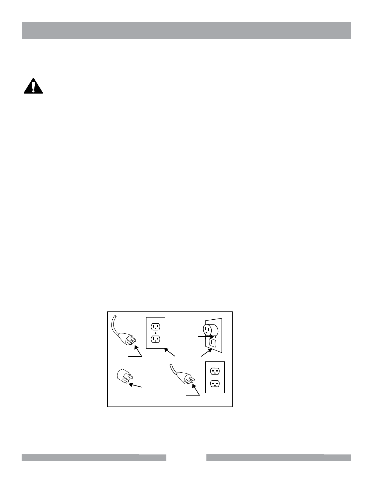
This tool is intended for use on a circuit that has an outlet that looks like the one shown in Sketch A.
The tool has a grounding plug that looks like the plug illustrated in Sketch A. A temporary adapter,
which looks like the adapter illustrated in sketches B and C, may be used to connect this plug to a
2-pole receptacle as shown in Sketch B, if a properly grounded outlet is not available. The temporary
adapter should be used only until a properly grounded outlet can be installed by a qualied electrician. The green-colored rigid ear, plug, and the like, extending from the adapter, must be connected
to a permanent ground, such as a properly grounded outlet box.
Metal Screw
Grounding
Pin
(A)
ADAPTER
Grounding
Means
(C)
Cover of
Grounded
Outlet Box
Grounding
Pin
(B)
(D)
Circuit and Adapter Information
Use of a temporary adapter is not permitted in Canada.NOTE:
NOTE:
If permanently connected this tool should be connected to a grounded metal permanent
wiring system; or to a system having an equipment - grounding conductor.
7
Page 8

HP18 & HP24 SAFETY
ELECTRICAL REQUIREMENTS AND GROUNDING INSTRUCTIONS
To avoid the possibility of the appliance plug or receptacle getting wet, position the saw to one side
of a wallmounted receptacle. This will prevent water from dripping onto the receptacle or plug. A “drip
loop," shown in picture below, should be arranged by the user to properly position the power cord relative to the power source.
The “drip loop" is that part of the cord below the level of the receptacle,
or the connector, if an extension cord is used. This method of positioning
the cord prevents the travel of water along the power cord and coming in
contact with the receptacle. If the plug or receptacle gets wet, DO NOT
unplug the cord. Disconnect the fuse or circuit breaker that supplies
power to the tool. Then unplug and examine for presence of water in the
receptacle.
Use only extension cords that are intended for outdoor use. These
extension cords are identified by a marking “Acceptable for use with
outdoor appliances; store indoors while not in use." Use only extension
cords having an electrical rating not less than the rating of the product.
Do not use damaged extension cords. Examine extension cords before using and replace if damaged.
Do not abuse extension cords and do not yank on any cord to disconnect. Keep cords away from heat
and sharp edges. Always disconnect the extension cord from the receptacle before disconnecting the
product form the extension cord.
To reduce the risk of electrocution, keep all connections dry and off the ground. Do not touch the plug
with wet hands.
Use of undersized extension cords result in low voltage to the motor that can result in motor burnout
and premature failure. Barranca Diamond warns that equipment returned to us showing signs of being
run in a low voltage condition, through the use of undersized extension cords, will be repaired or
replaced totally at the customer's expense. There will be no warranty claim.
To choose the proper extension cord:
• Locate the length of extension cord needed in the table below.
• Once the proper length is found, move down the column to obtain the correct AWG size required for
that length of extension cord.
EXTENSION CORD LENGTH
Nameplate
Amperes
0 - 5 16 16 16 14 12 12
5.1 - 8 16 16 14 12 10 •
8.1 - 12 14 14 12 10 • •
115V 25' 50' 75' 100' 150' 200'
250V 50' 100' 150' 200' 300' 400'
12.1 - 15 12 12 10 10 • •
15.1 - 20 10 10 10 • • •
8
Page 9

HP18 & HP24 SPECIFICATION
Model# HP18 HP18 HP24
Motor Baldor Baldor Baldor
Horsepower 1.5 Hp 1.5 Hp 1.5 Hp
Voltage 120V / 60 Hz 120V / 60 Hz 120V / 60 Hz
Amperage 8 8 8
Motor RPM 1725 1725 1725
Blade RPM 700 700 500
Arbor Size 1” 1” 1”
Blade capacity 16”- 20” 16”- 20” 20”- 24”
Depth of Cut 7.5" (w/ 18" Blade) 8" (w/ 20" Blade) 10” (w/ 24"
Blade)
Vise Opening 8” 8” 17”
Blade Included 18" 301 or 303S 20" 301 or 303S 24” 301 or 303S
Saw L x W x H 51” x 37” x 49” 51” x 37” x 49” 65” x 37” x 48”
Dry Weight 580 lbs. 580 lbs. 720 lbs.
Part Number 8302018 8302020 8302024
MOTOR
Single Phase, Continuous Duty commercial grade motor with automatic thermal overload protection.
Manual reset button on HP18 and HP24 Baldor motors. Export motor 230 volts 50Hz can be ordered
with either saw.
FEED MECHANISM
Stainless steel screw rod with silicon bronze threaded clutch block engagement system. Silicon bronze
spur to hardened steel worm gear to belt pulley drive.
LUBRICATING SYSTEM
Blade splash system using petroleum or mineral oil based lubricant. Water should NEVER be used as
a lubricant in any of the Highland Precision series saws as it will adversely affect cutting performance,
blade life, power feed, iron/steel components, and create bearing problems with the saw.
LUBRICANT REFERENCE
HP18: 9-1/4 gallons with 18” blade, 4-1/4 gallons with 20” blade.
HP24: 19 gallons with 24” blade
Refer to page 12
CARRIAGE & VISE MATERIAL
Cast Iron.
CARRIAGE RAILS
Steel rod.
9
Page 10

HP18 & HP24 SPECIFICATION
SHAFT BEARINGS
Sealed flange mount ball bearings with zerk fittings for grease lubrication.
CARRIAGE FEED ENGAGE/DISENGAGEMENT
Lever operated clutch system using silicon bronze shoe with block (adjustable set screws).
INDEXING OR ROCK CUT WIDTH CONTROL
Crank handle operated stainless steel screw system.
TANK & HOOD COVER CONSTRUCTION
11 gauge steel box-construction 12 gauge hood with acrylic plastic viewing window.
TANK LEGS
11 gauge steel construction with locking casters on HP18 and HP24 saws.
OIL SLUDGE DRAIN
2” drain cap on HP18 and HP24 saws. Drain placement is on bottom of saw tank.
ON/OFF AUTOMATIC POWER CONTROL
HP18 and HP24 saws have adjustable chain for automatic shut-off control of power on/off switch.
DEPTH OF CUT
24” blade: 10 inches,
20” blade: 8 inches
18” blade: 7.5 inches
MATERIAL TYPES
Barranca Diamond Highland Precision Slab Saws can cut a variety of material types including lapidary
rock, natural and artificial glass, and gemstone minerals.
NOTE: Highland Precision Slab Saws are not designed to cut wood, ice, synthetics, graphite carbon,
plastics, or ferrous metal materials.
UNPACKING & ASSEMBLY
Your Highland Precision Slab Saw has been shipped from the factory thoroughly inspected and tested.
The blade has been factory installed and arbor nut securely tightened. No assembly is required. Do
not over-tighten the arbor nut prior to use.
Remove the saw from the pallet by unbolting legs from crate pallet and place it on a flat surface using
a forklift. Install casters on legs – one at a time - on HP18 and HP24 saws prior to operation.
10
Page 11

HP18 & HP24 SPECIFICATION
CONTENTS
In the wood crate, you will find one (1) Barranca Diamond Highland Precision Slab Saw, one (1) 303 segmented diamond blade, one (1) owner’s manual, one (1) warranty card, and 4 leg casters (HP18 & HP24).
TRANSPORT
WARNING
Highland Precision Slab Saws weigh between 550 (HP18) and 750 (HP24)
pounds dry. Do not attempt to move a saw that is not mounted on casters without a forklift or floor jack.
Place the hood in the DOWN position and latched when transporting.
Be sure power cord is disconnected.
11
Page 12

HP18 & HP24 OIL/COOLANT
RECOMMENDED CUTTING OILS
Never run a diamond blade dry as this can immediately damage your blade. Use one of the oils/coolants recommended
below. Coolant should be kept clean and below 100° F. Sludge should be removed periodically and replaced with fresh
coolant so that your cuts will be clean and your blades will not be damaged.
Shell Diala Ax
Non-hazmat replacement oil for electrical transformer cooling. Excellent lubricating properties for blades and saw parts.
Flushes sludge from rock easily, degreases easily, and sludge settles in saw tank well. In Southern California, Shell Diala
Ax can be purchased from Dion and Sons, Inc (www.dionandsons.com).
Chevron Texaco Bright-Cut
A chlorine-free cutting oil with reduced sulfur and fat content. Light in color and low in odor.
Hyvolt II
Electrical transformer cooling oil. A highly rened petroleum product, available from some non-Shell oil distributors, typically only in 55 gallon drums. Same properties and performance as Shell Amber Neutral 100.
Chevron Superla #5
Food grade mineral oil. Non-hazardous lubricating oil for bakeries, breweries and food processing machinery. Good lubricating properties, degreases and settles sludge well. Can go rancid over time (1 year or less).
AVATEC 80
Food grade mineral oil, excellent for slab sawing in all our slab saws.
Texaco ALMAG
Pure petroleum based machining cutting oil. Good for slab sawing but very strong odor. Often the cheapest priced oil
available but odor is tough to eliminate.
Roc Cut
Roc Cut from Diamond Pacic is a new synthetic water soluble cutting additive with rust inhibitors. Mix 30 to 1 (water to
Roc Cut).
Roc-Oil
Roc-Oil from Diamond Pacic is an oil coolant for heavy duty cutting. Provides excellent blade protection and will not
cause rust to your blade or saw.
Under NO circumstances should any of the following fluids be used in any of our lapidary saws:
Automotive Antifreeze Coolant
Ethylene glycol based automotive antifreeze and its vapors are considered hazardous and toxic. Propylene glycol based
antifreeze is nontoxic but has practically no lubricating properties; it functions as a coolant only and its use will lead to
rapid blade wear and dulling.
Automotive Transmission Fluid
Does not have adequate lubricating proprieties for our saws; vapors are considered hazardous and toxic.
Water
A good coolant but has no lubricating properties and causes rust and degradation of exposed iron and steel parts. Causes
rapid blade dulling and premature wear. Use of water voids the warranty on all Barranca Diamond saws.
CNC Machining Fluids
Water soluble synthetic coolants (i.e. Valenite or Cimtool) are often mixed in a 20:1 blend with water. Fluid vapors are
considered hazardous. These uids do not have adequate lubricating or rust inhibiting properties for the cast iron and
steel parts in our slab and trim saws.
Diesel, Heating Oil and Kerosene
Very ammable with a low ash point. At least 3 of our commercial cutting customers in Arizona and Pacic Northwest
have burned down their shops using these uids. Can be very tough to degrease the residue and aroma out of the cut
slabs. These uids are cheap, but very hazardous to use. Diesel is a benzene compound which is carcinogenic. All these
uids can cause severe skin rashes and other ailments.
12
Page 13

HP18 & HP24 STARTUP & ADJUSTMENT
PRE-START INSPECTION
The pre-start inspection should be performed before beginning any job.
1. Check Oil Level
Oil should always cover at least 1/4" to 3/8" of the bottom of the blade (Kerf should be completely covered). Do not overfill the reservoir tank!
2. Check Blade
CAUTION
STAR TUP
Saw Lubricant
The saw tank reservoir should be filled with oil to a point 1/4" to 3/8" of the bottom of the blade. This
ensures adequate lubrication for the blade’s diamond notched segments and allows for splashing of
the oil onto the rock carriage, vise, rails and screw thread
for lubrication and rock mud flushing into the tank. Never
place more than 3/4 inch of oil over the bottom of the
blade as this overfilling will result in more friction and
work for the blade and motor to overcome the excess oil
causing motor and belt overheating. Periodically check
the oil tank level after each day of use to ensure an adequate level of lubricating oil in the tank. Expect loss of
cutting oil over time due to misting, absorption into the
rock material and heat evaporation.
Check blade signs for core or segment cracks, uneven segment wear, pounding
out of round arbor hole, undercutting, segment loss, dishing or loss of tension.
If the diamond blade shows signs of any of these problems the blade must be
replaced before starting work. A damaged blade will not cut correctly and could
cause physical injury.
Power Switch (HP18 & HP24)
The motor requires no special preparation or adjustment prior to use of the slab saw. The on/off power
control toggle switch is located on the front of the saw. Pull the toggle switch away from the saw to
start the electric motor. Push the toggle switch toward the saw to stop the electric motor.
13
Page 14

HP18 & HP24 STARTUP & ADJUSTMENT
Automatic Shutoff (HP18 & HP24)
Once a rock specimen has been securely vised inside of
the saw, the operator can adjust the automatic shut-off
control switch by moving the link chain to the desired
position where the rock and vise are anticipated to
complete the desired cut. By moving the vise forward
with the rock in place, the operator can see where the
chain slack needs to be adjusted to stop the unit
automatically. Movement of the vice will tension the chain
to a point where it will pull the ON/OFF switch to the OFF
position and shut-off the power feed and blade shaft motor
automatically.
HP18 & HP24 power switch
New Blade Break-In Procedure
Be sure to wipe off any and all carbide or abrasive grit particles
from the cross and main feed screw rod and rails. It is recommended, upon initial use of the Highland Precision slab saws, to cut material that is abrasive yet soft such as carbide brick or cinder block
to remove the factory paint and open the blade’s diamond segment
for optimal cutting performance. Use of a sharpening stone such as
aluminum oxide or carborundum is acceptable only if the sharpening brick is placed securely in the vise.
HP18 & HP24
Automatic shut-off chain &
adjustment to carriage hook
14
Page 15
HP18 & HP24 STARTUP & ADJUSTMENT
Never operate the saw with the hood up, or hold a sharpening stone to the blade by hand. Use of the
vise is mandatory under all operation conditions. Never over-sharpen the blade too much as it will cut
down the blade life. Periodically, the diamond blades should be "dressed open" or sharpened by making several passes through a green carbide brick, aluminum oxide (60-100 grit), or abrasive stone such
as cinder block or red brick.
Should the saw experience difficulty in cutting, inspect the diamond blade for loss of tension, temper,
wobble, pounding, dishing, or glazing of the diamond cutting edge (kerf). Resharpening of the blade
may be required periodically when cutting dense and hard material. Segmented rim and continuous
rim 303 Pro blades are NOT repairable. Be sure blade flanges are at least 1/6 the blade diameter (i.e.
a 24" blade requires a set of flanges at least 4" in diameter). Undersized flanges will result in blade tension loss.
ADJUSTMENT AND OPERATION
Cutting Setup:
CAUTION
DO NOT FORCE the blade to cut, it will do the job better and safer at a rate for
which it was designed.
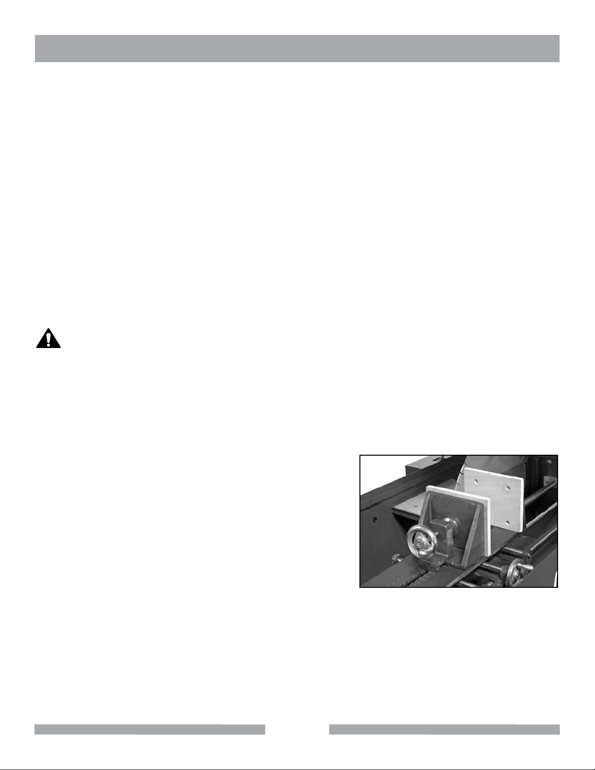
Rock Vise/Carriage Operation
The carriage and rock vise work together to securely hold the rock specimens during movement of the
material in the carriage toward and into the notched rim diamond blade. The rock specimen should
not exceed the maximum material size for the saw you are using (as shown in the table on the saw
specifications page). It is very important that the rock specimen be tightened by use of the hand screw
threaded bolt at the back of the rear vise plate once the specimen has been pushed forward and in firm contact with the
front plate. Both front and rear vise plates are constructed of
1/2" plywood to give firm and tight grip to the rock specimen.
Should replacement be needed due to wear or breakage,
the parts can be ordered from Barranca Diamond Products.
Wedges of wood can be used in the voids between the rock
specimen and vise plates to enhance the surface contact and
pressure hold prior to tightening the vise screw bolt. Be sure
to recheck the tightening screw prior to operation.
Carriage and rock vise
15
Page 16

HP18 & HP24 STARTUP & ADJUSTMENT
Handle Crank Cross Feed Adjustable Rock Cut Index Control
To use the crank cross feed index wheel, simply clamp and
secure the cutting material into the vise by using the clamp
screw to tighten the vise and turn the wheel crank until the
desired slab thickness is achieved You can measure the
slab thickness with a ruler prior to cutting, but remember,
depending on blade thickness, the amount of waste material
from the rock specimen will vary. Always allow the rock cut
to go to completion before opening the hood of the saw. Do
not over crank the vise to the far left or right position on the
carriage.
Cross feed index, crank the handle
and clutch lever assembly
Automatic Feed Engagement/Disengagement System
Highland Precision slab saws are designed for operation with an adjustable clamping vise and selffeeding carriage mount. The clutch engagement/disengagement lever should be positioned in the
straight upward (12 o'clock) position to disengage the clutch and allow the carriage to move freely
along the rails. To engage the clutch, simply turn the lever in the downward (3 or 9 o'clock) position to
securely engage the bronze shoe and block with the stainless steel thread. Should the carriage not
move freely on the rails, clean the rails with a clean rag and place a liberal amount of wheel bearing
grease on all surfaces of the steel rails to assist in the free movement of the carriage.
Clutch lever in disengaged position
Clutch lever in engaged position
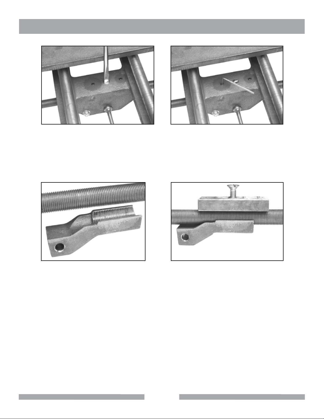
Clutch Adjustment
The clutch system is comprised of a lever to cam assembly that raises and lowers a bronze clutch
shoe. Should the clutch not fully engage and move the carriage, loosen the countersink screw below
the vise table inside of the carriage and tighten the two allen head screws to depress the bronze pressure block. Adjust set screws in one-half turn increments. Be sure to retighten countersink screw after
each adjustment. Re-engage the clutch and restart saw to check if feed is working properly. If not,
readjust set screws another 1/2 turn, retighten countersink screw and restart saw to check feed.
16
Page 17
HP18 & HP24 STARTUP & ADJUSTMENT
Adjusting countersink screw
Adjusting allen head screw
This adjustment will help the clutch block shoe to snugly engage the stainless steel feed screw by applying pressure to the brass pressure block below the carriage casting. Should you have trouble with
this adjustment, call Barranca Diamond at (800) 630-7682 for factory assistance in clutch adjustment.
Feed screw & clutch block shoe
Brass pressure block, feed
screw & clutch block shoe
Periodically, it will be necessary to replace the silicon bronze clutch block shoe once the 5/8"-18
threads are flattened or stripped. You may purchase the clutch block and pressure block direct from
the factory. See parts lists on pages 27 & 33 to order correct parts by part number and description of
part(s).
17
Page 18
HP18 & HP24 MAINTENANCE
MAINTENANCE FOLLOWING USE
The following maintenance should be performed following each use.
WARNING
Place the ON/OFF switch in the OFF position and unplug cord prior to servicing
and when changing accessories, such as blades, belts, and the like.
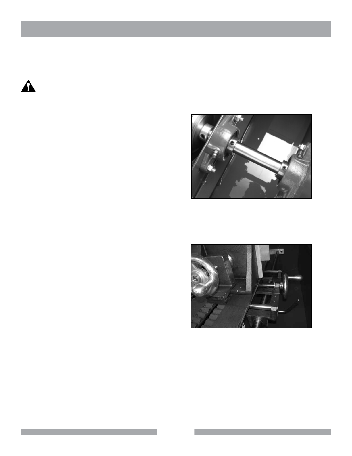
Blade-Shaft Bearings
Remove sheet metal cover over blade shaft
and grease zerk fittings on base mount bearings. Use premium wheel bearing grease to
lubricate all blade-shaft bearings.
Cross-Adjustment Rail System
No grease or applied lubrication is required for the
stainless steel screw feed and cross-adjustment
rail system. The slab saw cutting oil splash will
adequately lubricate the vice screw-feed, rails and
clutch parts. If the
carriage becomes hard to slide over the rails, clean
the rails with a rag and apply a liberal amount of
wheel bearing grease to the surface of the steel
rails to facilitate travel of the carriage over the rails.
Shaft bearings
18
Cross-adjustment rail system
Page 19

HP18 & HP24 MAINTENANCE
GENERAL MAINTENANCE
Oil Sludge Removal from Reservoir
Use plumber's pipe wrench to remove drain cap. Allow free liquid to drain to a pan. Use a spatula to
remove sludge from tank bottom toward drain hole. Use of plumbers tape on the drain pipe threads will
adequately seal the cap to thread contact to prevent leaks.
MONTHLY MAINTENANCE
The following should be performed monthly. Items should be lubricated as directed.
Shaft Bearings
Grease zerk fittings on sealed ball bearing every 20 to 30 hours of use. Rotate shaft periodically while
greasing zerk fittings.
Drive Belts
The belt tension from the motor to blade shaft and worm drive gear are factory preset for immediate
operation. However, the belt tension can be adjusted by adjusting the motor mount plate under the oil
reservoir box with an open end wrench.
Periodically, the belt tension should be checked by removing the belt guard metal cover and ensure at
least 1/2 to 3/4 inch of belt defection is observable. Never over tighten the drive belt as premature motor, bearing and pulley wear may occur. Even though the idler pulley contains sealed ball bearings that
do not require lubricant, a small amount of spray oil lubricant
or grease can be used periodically to keep the idler shaft
and pulley in free spinning condition. Do not allow oil or
lubricant to come in contact with the v-belts. Always ensure
the spring on the idler pulley arm is attached and not damaged. Some periodic lubrication at the idler shaft/pulley will
be necessary. Use a light oil for this bearing to shaft contact
surface.
Belt tensioning assembly
Blade shaft to motor worm gear
shaft pulleys and belts
Idler pulley assembly
19
Page 20

HP18 & HP24 MAINTENANCE
Worm Shaft and Pinion Gear Lubrication
The worm drive shaft and pinion gear lubrication box on the rear of the saw should be checked for
adequate grease lubrication periodically. Remove cover to check lubricant, remove the box by removing the four mounting screws that attach the box to the rear of the saw reservoir. Check the level of the
grease lubricant in the box by ensuring that gear box is filled so that at least 1/3 of the volume of the
box (up to 1 to 1 1/2 inches from bottom of box) such that the bottom of the bronze gear teeth are immersed in the lubricating grease. A common automotive bearing lithium or moly type grease lubricant
should be used. The bronze pinion gear and worm shaft will need to break-in as the unit is first used
causing some heat to build up on the gear shaft and lubricant box during this initial break-in period.
The grease level in the box should be checked and refilled if necessary after approximately 2 to 3
hours of initial use, be sure the worm and bronze gear teeth mesh together. A premium grade wheel
bearing grease for high temperature use is recommended.
Worm drive shaft and pinion gear
lubrication box
Worm drive shaft and pinion gear
(cover removed)
Diamond Blade Change-Out
Hold blade in one hand and use a wrench to turn shaft nut counterclockwise and remove nut and
flange from shaft. After reinstalling blade, replace flange and nut and retighten. Do not over tighten
shaft nut.
Lubrication Points
Use premium grade wheel bearing grease when lubricating the saw. Clean the zerk fitting when finished lubricating. Apply grease slowly; stop when grease is seen between joints. Rotate blade and
driveshaft slowly by hand to spread grease uniformly into ball bearings.
V-Belt Inspection, Adjustment and Replacement
Look for frayed or split belts. Tighten belts for 1/2" to 3/4" of deflection from center of belt. Do not over
tighten.
20
Page 21

HP18 & HP24 TROUBLESHOOTING
TROUBLESHOOTING
Saw Will Not Start
Check power cord and receptacle.
Motor Overheating
If motor overheats allow to cool for 2 to 3 hours, push reset
button with power disconnected, hookup power cord and resume
cutting by pulling the power switch to the ON position. All motors
have automatic thermal protection and will shut off if overheated.
Do not use long (25"+) drop cords.
Vise carriage can not be moved by hand when clutch is disengaged
Adjust clutch by loosening the slotted locking screw, turn 2 allen set screws 1/2 turn clockwise, retighten slotted locking screw. Check to see if carriage is disengaged from screw feed by placing clutch
lever in 12 o'clock
position and moving carriage by hand over rails.
Vise carriage does not move automatically when clutch is engaged
Clutch block thread may be stripped or worn. Remove and replace bronze clutch block.
Motor reset button
Blade will not cut properly
Check for damage or glazed diamond cutting kerf (segments). Replace damaged blades or resharpen
dull segmented blades.
21
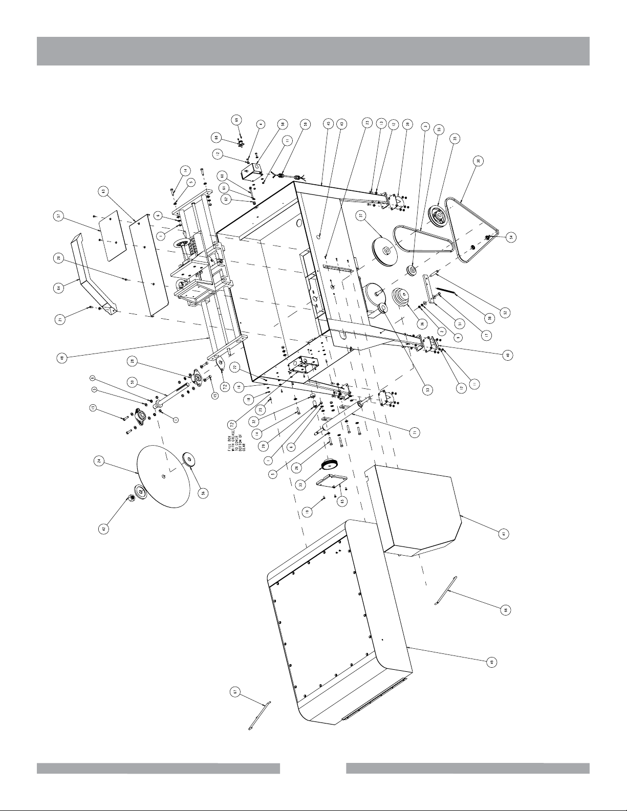
Page 22

HP18 EXPLODED VIEW
HP18 Highland Precision Slab Saw Part# 8302018
22
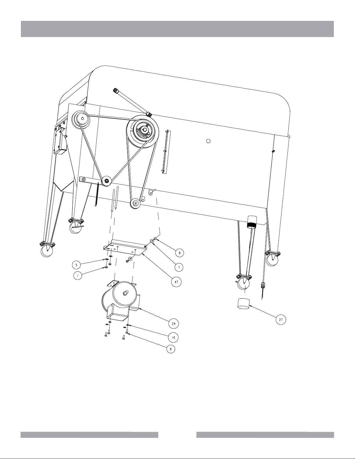
Page 23

HP18 EXPLODED VIEW
HP18 Highland Precision Slab Saw Part# 8302018
23
Page 24

HP18 PARTS LIST
HP18 Highland Precision Slab Saw Part# 8302018
ITEM DESCRIPTION PART # QTY.
1 NUT, HEX, 3/8 - 16 101188 13
2 NUT, HEX, 5/16 - 18 101196 1
3 PULLEY 2 - 3/4 X 5.8 134668 1
4 SCREW, HEX HEAD, 1/4 - 20 X 5.8 150404 2
5 WASHER, 3/8 SAE FLAT 150923 24
6 WASHER, 3/8 SPLIT LOCK 150925 11
7 5/16 FENDER WASHER 151053 4
8 SCREW, 5/16 - 18 X 3/4 HEX HEAD MACHINE 151369 6
9 WASHER, LOCK, SPLIT, 5/16 151747 1
10 WASHER, FLAT, SAE, 5/16 151747 5
11 NUT, HEX, 1/4 - 20 151893 18
12 WASHER, 1/4 SAE FLAT 151915 36
13 SCREW, HEX HD, 1/4 - 20 X 3/4 152370 16
14 SCREW, 3/8 - 16 X 1 - 1/2 15 3528 7
15 SCREW, 3/8 - 16 X 2 -1/4 HEX HEAD 153529 1
16 WASHER, #10 SPLIT LOCK 153684 6
17 SCREW, 5/16 - 18 X 1 - 1/4 HEX HEAD MACHINE 153950 1
18 WASHER, #10 SAE FLAT 154369 12
19 SCREW, 1/4 - 20 X 1/2 PAN HEAD PHILLIPS MACHINE 155 452 4
20 SCREW, FLAT HEAD, 1/4 - 20 X 1/2 PHIL 155812 3
21 SCREW, 5/16 - 18 X 1/2 SOCKET HEAD CAP 156139 1
22 NUT, HEX 10 - 32 156269 6
23 SCREW, PAN HD SELF TAP 8 - 32 X 1/2 156 632 3
24 BLADE, 18" 156729 1
25 SCREW, 10 - 32 X 1/2 SOCKET HEAD SET 157525 6
26 SCREW, 3/8 - 16 X 1 - 3/4 HEX HD 158398 3
27 MOTOR, 1.5HP 60HZ 1725 R.P.M IPH 161099 1
28 BEARING, BALL 1/2" ID X 1 - 1/8 OD FLANGE 161363 2
29 BUSHING, BRONZE FLANGED 3/4 X 1/2 X 1 -1/4 161372 1
30 BELT, V A - 60 161412 1
31 PIPE CAP, 2" NPT 161468 1
32 COLLAR, SHAFT 3/4 X 1 - 1/4 X 9/16 161494 1
33 GEAR, SPUR 4" OD X 1/2" BORE 48 TOOTH 161577 1
34 NUT, WING FLANGE 3/8 - 16 161718 1
35 PULLEY 6" 1OD. X 1" BORE 1617 78 1
36 PULLEY, STEP CONE 3.4.5 X 5/8 BORE 161784 1
24
Page 25

HP18 PARTS LIST
HP18 Highland Precision Slab Saw Part# 8302018
ITEM DESCRIPTION PART # QTY.
37 PULLEY, V 8" X 1" BORE 161800 1
38 SPRING, EXTENSION 162337 1
39 WHEEL., CASTER 2 X 1 - 1/4 162344 2
40 WHEEL, CASTER 3 X 1 - 1/4 162794 2
41 MANUAL, OWNER'S 164269 1
42 NUT, HEX 1" - 12 UNF 165038 1
43 CAP, FINISHING 165483 2
44 PALLE, SHIPPING 166218 1
45 TANK WELDMENT 166297 1
46 MOUNT, MOTOR 166299 1
47 GUARD, BELT 166300 1
48 ASSEMBLY, VISE 166372 1
49 ASSEMBLY, HOOD 166373 1
50 SHAFT, ARBOR 16 6374 1
51 TENSIONER BRACKET 166 396 1
52 SHAFT, TENSIONER 166425 1
53 PULLEY, ASSEMBLY 166426 1
54 RING, RETAINING 1/2" 166 427 1
55 BELT, V A-48 166 495 1
56 FLANGE, BLADE 166 496 2
57 WINDOW, GUARD 166497 1
58 SWITCH, ASSEMBLY, ON/OFF 166503 1
59 COR, POWER ASSEMBLY, ON/OFF SWITCH 166505 1
60 LEVER, ON/OFF SWITCH 166511 1
61 CHAIN, ON/OFF SWITCH 166512 1
62 GROMMET, ON/OFF LEVER 166513 1
63 TABLE, ARBOR HOUSING 166640 1
64 WELDMENT, SPLASH HOOD 166691 1
65 COVER, GEAR BOX 166705 1
66 GAS SPRING 50LBS. 166706 1
67 GAS SPRING 50LBS, LOCKING 166707 1
68 LATCH, HOOD 166985 1
25
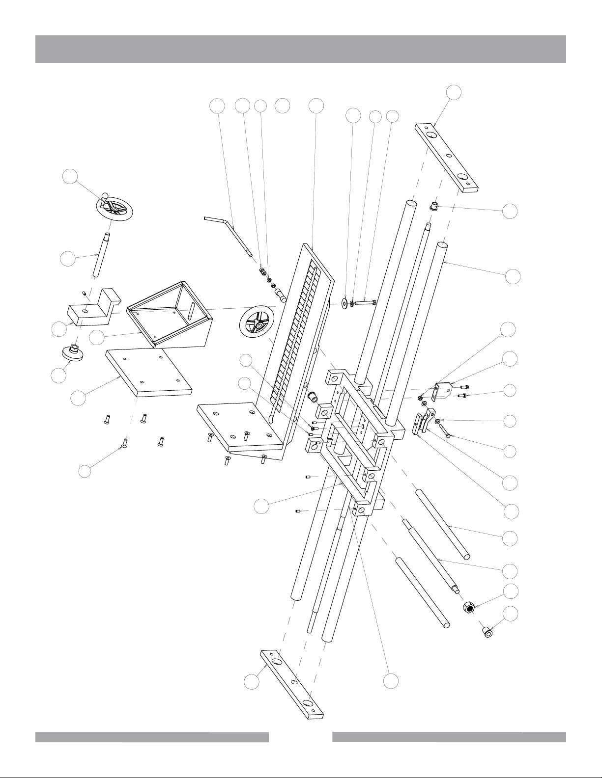
Page 26

HP18 EXPLODED VIEW
HP18 Assembly, Vise Part # 166372
31
16
19
6
25
26
34
2
11
33
24
12
1
4
10
28
14 15
22
13
27
3 8
30
5
32
7
6
9
21
20
29
SCALE 0.375
23
18
17
26
Page 27

HP18 PARTS LIST
HP18 Assembly, Vise Part # 166372
ITEM DESCRIPTION PART # QTY.
1 WASHER, FLAT, SAE, 5/16 151754 1
2 NUT, HEX, 1/4 - 20 151893 2
3 WASHER, FLAT, SAE, 1/4 151915 2
4 SCREW, 5/16 - 18 X 2 HEX HEAD 155494 1
5 SCREW, 5/16 - 18 X 1.0 FLAT HEAD SOCKET 155552 8
6 SCREW, 1/4 - 20 X 1/2 SOCKET HEAD SET 155804 3
7 SCREW, FLAT HEAD, 1/4 - 20 X 1/2 PHIL 155812 1
8 SCREW, HEX HD, CAP, 1/4 - 20 X 2 - 1/4 157528 3
9 SCREW, SOC HD SET 1/4 - 20 X 1/4 156607 3
10 NUT, HEX, NYLK, 1/4 - 20 159857 1
11 COLLAR, SHAFT 1/4 X 1/2 161066 2
12 WASHER USS 7/16" 162017 1
13 CLUTCH, SHOE UPPER BLOCK 162197 1
14 BUSHING, BRONZE FLANGED 5/8 X 1/2 X 3/4 162304 1
15 BUSHING, BRONZE FLANGED 3/4 X 1/2 X 7/8 162306 1
16 WHEEL, HAND 4 - 1/2" 164915 2
17 ROD, 3/4 DIA. X 14 - 3/8" LG. 166388 2
18 ROD, THREADED SIDE TO SIDE 166389 1
19 ROD, THREADED 5/8 - 11 X 6 -/18" LG. 166 390 1
20 ROD, FEED 5/8 - 18 X 44 - 3/4 166 391 1
21 ROD, LENGTH SLIDE 1 - 1/4 X 43 166392 2
22 BRACKET, CLUTCH LEVER 166397 1
23 CARRIAGE COMPLETE 166399 1
24 VISE, COMPLETE 166 40 0 1
25 DOG, COMPLETE 166401 1
26 JAW, COMPLETE 166402 1
27 SHOE, CLUTCH COMPLETE 166415 1
28 SUPPORT BAR, RIGHT 166416 1
29 SUPPORT BAR, LEFT 16 6417 1
30 WOOD, JAW COMPLETE 166431 1
31 LEVER, CLUTCH 16 64 32 1
32 WOOD, VISE COMPLETE 166 43 3 1
33 CAM, CLUTCH 166486 1
34 MOUNT, LEVEL SWIVEL 166704 1
27
Page 28
HP24 EXPLODED VIEW
HP24 Highland Precision Slab Saw Part# 8302024
28
Page 29
HP24 EXPLODED VIEW
HP24 Highland Precision Slab Saw Part# 8302024
29
Page 30

HP24 PARTS LIST
HP24 Highland Precision Slab Saw Part# 8302024
ITEM DESCRIPTION PART # QTY.
1 NUT, HEX, 3/8 - 16 101188 17
2 NUT, HEX, 5/16 - 18 101196 8
3 PULLEY 2 - 3/4 X 5.8 134668 1
4 SCREW, HEX HEAD, 1/4 - 20 X 5.8 150404 2
5 WASHER, 3/8 SAE FLAT 150923 32
6 WASHER, 3/8 SPLIT LOCK 150925 11
7 WASHER, FENDER 5/16 x1.0 151053 4
8 SCREW, 5/16 - 18 X 3/4 HEX HEAD MACHINE 151369 6
9 WASHER, LOCK, SPLIT, 5/16 151747 8
10 WASHER, FLAT, SAE, 5/16 151747 20
11 NUT, HEX, 1/4 - 20 151893 45
12 WASHER, 1/4 SAE FLAT 151915 89
13 SCREW, HEX HD, 1/4 - 20 X 3/4 152370 16
14 SCREW, HEX HD CAP, 1/4 - 20 X 1 152676 26
15 SCREW, 3/8 - 16 X 1 - 1/2 HEX HEAD 153528 4
16 SCREW, 3/8 - 16 X 2 -1/4 HEX HEAD 153529 1
17 SCREW, 5/16 - 18 X 1 - 1/4 HEX HEAD MACHINE 153950 9
18 SCREW, 1/4 - 20 X 3/4 FLAT HEAD PHILLIPS MACHINE 154657 4
19 SCREW, PAN HD, CAP, 1/4 - 20 X 1/2 155 452 7
20 BLADE, 24 X 1.0, 303S 156731 1
21 FHS, 1/4 - 20 X 1' 157527 1
22 SCREW, 3/8 - 16 X 1 - 3/4 HEX HD 158398 6
23 COLLAR, SHAFT 1/4 X 1/2 161066 1
24 MOTOR, 1/5HP 60HZ 1725R.P.M 1PH 161099 1
25 BEARING, BALL 1/2" ID X 1 - 1/8 OD FLANGE 161363 2
26 BUSHING, BRONZE FLANGED 3/4 X 1/2 X 1 -1/4 161372 1
27 PIPE CAP, 2" NPT 1614 68 1
28 COLLAR, SHAFT 3/4 X 1 - 1/4 X 9/16 161494 1
29 GEAR, SPUR 4" OD X 1/2" BORE 48 TOOTH 161577 1
30 NUT, WING FLANGE 3/8 - 16 161718 1
31 PULLEY 6" 1OD. X 1" BORE 1617 78 1
32 PULLEY, STEP CONE 3,4,5 X 5/8 BORE 161784 1
33 3/16" ACRYLIC 162032 1
34 BELT, A68 162293 1
35 SPRING, EXTENSION 162337 1
36 WHEEL, CASTER 3 X 1 - 1/4 162344 2
30
Page 31

HP24 PARTS LIST
HP24 Highland Precision Slab Saw Part# 8302024
ITEM DESCRIPTION PART # QTY.
37 WHEEL, CASTER 3 X 1 - 1/4 162794 2
38 BELT, A57 163098 1
39 MANUAL, OWNER'S 164269 1
40 WELDMENT, HOOD 164949 1
41 WELDMENT, TANK 164950 1
42 WELDMENT, BELT GUARD 164951 1
43 TABLE, ARBOR 164953 1
44 NUT, HEX 1" - 12 UNP 165038 1
45 CAP, FINISHING 165483 1
46 PALLET, SHIPPING 166219 1
47 MOUNT, MOTOR 166299 1
48 TENSIONER BRACKET 166396 1
49 SHAFT, TENSIONER 66425 1
50 PULLEY, ASSEMBLY 166426 1
51 RING, RETAINING 1/2" 166427 1
52 FLANGE, BLADE 166496 2
53 SWITCH, ASSEMBLY, ON/OFF 166503 1
54 PLUG, FINISHING 3/4" 166504 1
55 CORD, POWER ASSEMBLY, ON/OFF SWITCH 166505 1
56 LEVER, ON/OFF SWITCH 16 6511 1
57 CHAIN, ON/OFF SWITCH 166512 1
58 GROMMET, ON/OFF LEVER 166513 1
59 COVER, GEAR BOX 166705 1
60 LATCH, HOOD 166985 1
61 SCREW, FLAT HD, PHILLIPS 10 - 32 X 3/8" 166 896 2
62 GASKET, BEARING 167049 1
63 PULLEY, 9" X 1" BORE 167365 1
64 ASSEMBLY, DRIVE SHAFT 167366 1
65 ASSEMBLY, VISE 167368 1
66 GASKET, GEAR BOX 167373 1
67 GASKET, WINDOW, LONG 167668 2
31
Page 32
HP24 EXPLODED VIEW
HP24 Highland Precision Vise Assembly Part# 167368
21
3
11
23
17
18
24
29
13
1
2
15
30
26
25
27
6
8
34
7
28
10
19 20
4 5
9
14
31 32
12
16
22
33
32
Page 33

HP24 PARTS LIST
HP24 Highland Precision Vise Assembly Part# 167368
ITEM DESCRIPTION PART # QTY.
1 BOLT, HEX HD TAP, 5/16 - 18 X 2 - 1/2 151748 1
2 WASHER, FLAT, SAE, 5/16 151754 1
3 NUT, HEX, 1/4 - 20 151893 2
4 WASHER, FLAT, SAE, 1/4 151915 4
5 SCREW, HEX HD, 1/4 -2 0 X 3/4 152370 2
6 SCREW, 1/4 -20 X 3/4 FLAT HEAD PHILLIPS MACHINE 154657 1
7 SCREW, 5/16 - 18 X 1.0 FLAT HEAD SOCKET 155552 8
8 SCREW, 1/4 - 20 X 1/2 SOCKET HEAD SET 155804 6
9 SCREW, HEX HD, CAP, 1/4 - 20 X 2 - 1/4 156607 1
10 NUT, HEX, NYLK, 1/4 - 20 159857 1
11 COLLAR, SHAFT 1/4 - 20 159857 2
12 NUT, HEX 3/4 - 16 BRASS 161706 1
13 WASHER USS 716" 162017 1
14 CLUTCH, SHOE UPPER BLOCK 162197 1
15 BUSHING, BRONZE FLANGED 5/8 X 1/2 X 3/4 162304 1
16 BUSHING, BRONZE FLANGED 3/4 X 1/2 X 7/8 162306 2
17 WHEEL, HAND 4 - 1/2" 164915 2
18 ROD, THREADED 5/8 - 11 X 6 - 1/8" LG. 166390 1
19 BRACKET, CLUTCH LEVER 166397 1
20 SHOE, CLUTCH COMPLETE 166415 1
21 SUPPORT BAR, RIGHT 166416 1
22 SUPPORT BAR, LEFT 16 6417 1
23 LEVEL, CLUTCH 166432 1
24 CAM, CLUTCH 16698 5 1
25 MOUNT, LEVEL SWIVEL 166704 1
26 DOG (COMP) 166984 1
27 JAW (COMP) 167139 1
28 CARRIAGE (COMP) 167140 1
29 VISE (COMP) 167141 1
30 ROD, VISE TRAVEL 167369 2
31 ROD, VISE SIDE TO SIDE 167370 2
32 ROD, THREADED SIDE TO SIDE 167371 1
33 ROD, THREADED FEED 167372 1
34 WOOD, BLOCK VISE (COMP) 167555 2
33
Page 34

HP-18 & HP24 WARRANTY
BARRANCA DIAMOND LIMITED WARRANTY
Please complete the warranty registration card and return. Any problems encountered should be directed to
Barranca Diamond Customer Service department at (800) 630-7682 M-F 8am - 5pm PST.
NOTE THIS INFORMATION FOR FUTURE USE:
MODEL NUMBER:
SERIAL NUMBER:
PURCHASE PLACE:
PURCHASE DATE:
Barranca Diamond warrants to the original retail purchaser for a period of 90 days except as noted, from the
date of purchase all products covered by this Warranty to be free of defects in materials and workmanship.
This Warranty shall not apply to any parts that have been subjected to misuse or improper service, that had
been damaged in transit or handling, or that have been altered or repaired by unauthorized representatives.
This Warranty does not cover defects caused by or resulting from misuse, abuse, neglect or damage caused
by accident or the failure to provide reasonable maintenance. This Warranty is void if the product or any of its
individual components is altered or modied by the purchaser or if the product is used in a manner or with a
blade not recommended by the manufacturer.
Any claim arising under this Warranty must be submitted by the original purchaser within the warranty period
specied above, and shall include proof of purchase. During said warranty period Barranca Diamond shall,
at its option, either replace or repair, at no charge to the original purchaser, any parts or components that are
found to be defective by Barranca Diamond. Barranca Diamond shall not be responsible for or obligated to
pay for freight or other transportation related costs or expenses in connection with any defective products or
components that are either returned to Barranca Diamond’s facility or any authorized repair station and/or any
replacement products or components that are shipped from Barranca Diamond pursuant to this Warranty.
Parts and labor needed to maintain products and the replacement of components due to normal wear and tear
are the purchaser’s responsibility and are not covered by this Warranty. All products or components replaced
under warranty become the property of the manufacturer. All replacement parts will be considered to be part
of the original product and any warranty on such parts will expire coincidentally with the original Warranty.
Barranca Diamond will pay for parts and labor in connection with warranty repairs conducted by Barranca Diamond or its authorized repair centers. Replacement part(s) installed by anyone else will be provided without a
charge for such replacement part(s), but this Warranty will not apply to labor charges in connection therewith.
IN NO EVENT SHALL ANY LIABILITY UNDER THIS WARRANTY EXCEED THE REPLACEMENT COST OF
ANY DEFECTIVE PRODUCT OR COMPONENT THEREOF, AND BARRANCA DIAMOND SHALL NOT BE LIABLE FOR ANY INCIDENTAL OR CONSEQUENTIAL DAMAGES OR FOR ANY OTHER DAMAGE OR LOSS
NOT EXPRESSLY ASSUMED AS SET FORTH HEREIN.
The foregoing constitutes an expressed warranty on the terms set forth above and is the only warranty or
warranties applicable to the products it covers. All other warranties, including, without limitation, the implied
warranty of merchantability and/or tness for a particular purpose or use being denied. This limited warranty is
expressly in lieu of all other warranties, whether expressed or implied.
34
Page 35

HP-18 & HP24 WARRANTY
SPECIFICS APPLICABLE TO LIMITED WARRANTY OF DIAMOND BLADES AND CORE BITS
Laser Welded Blade and Bit Warranty
If the laser weld between the segment and the steel core or barrel fails during normal use, the blade or bit will
be replaced free of charge. Blades and bits damaged due to careless or improper use are not covered under
this warranty.
Brazed Blade, Bit, and Cup Wheel Warranty
If the brazed bond between the segment and the core, barrel, or cup fails within the rst .050 of segment wear,
the blade, bit, or cup will be replaced free of charge. Blades, bits, and cup wheels damaged due to careless or
improper use are not covered under this warranty.
Continuous Rim Blade Warranty
If the bond between the rim and the core fails during normal use, the blade will be replaced free of charge.
Blades and bits damaged due to careless or improper use are not covered under this warranty.
Exclusions
Barranca Diamond does not warrant the following components, which carry their own manufacturer’s warranty
for the indicated periods:
Electric Motors Manufacturer’s Warranty
Baldor: 1 year
Ryobi: 1 Year
Soga: 1 Year
Gas Engines Manufacturer’s Warranty
Honda: 2 years
Engine Power Information
Engine power ratings are calculated by the individual engine manufacturer and the rating method may vary
among engine manufacturers. Barranca Diamond Products makes no claim, representation or Warranty as to
the power rating of the engine on this equipment and disclaims any responsibility or liability of any kind whatsoever with respect to the accuracy or the engine power rating. Users are advised to consult the engine manufacturer’s owner's manual and website for specic information regarding the engine power rating.
35
Page 36

HP-18 & HP24 SERVICE & WARRANTY
REPLACEMENT PARTS
Replacement parts for this tool may be ordered form your Barranca Diamond distributor or directly from
Barranca Diamond. Please have the following information ready before calling:
• Model and serial number of the machine
• Date of purchase
• Description of parts being ordered (see attached parts list)
RETURN MATERIALS PROCEDURE
To expedite the service relative to the return of a product purchased through Barranca Diamond, please have
the following information available:
• Model and serial number of the machine
• Date of purchase
• Distributor’s name
Then please call Barranca Diamond at (310) 523-5867 or toll free at 800-630-7682 to obtain a Return Goods
Authorization number (RGA) authorizing the return.
Please Note:
• Ensure your item(s) are prepaid to the destination
• Return items must have been purchased within the previous twelve (12) months
• Follow the packaging instructions in the following section
• Be sure to include the RGA number, return address and your phone number on or within the
return shipping box.
PACKAGING INSTRUCTIONS
Ship the saw using its plywood shipping crate. Use wood screws to fasten the baseboard to the 1/2” plywood
crate bottom so as to secure it inside the shipping crate.
36
Page 37

NOTES
37
Page 38

NOTES
38
Page 39

NOTES
39
Page 40

Barranca Diamond Products, Inc.
1315 Storm Parkway
Torrance, CA 90501
Toll-Free: (800) 421-5830
Phone: (310) 539-5221
Fax: (310) 539-5158
www.barrancadiamond.com
 Loading...