

Page 1
SUPER CABMAKER-GP8
OWNER’S MANUAL AND
OPERATING INSTRUCTIONS
Revision 101 11. 2012
Manual Part No. 168687
Caution: Read all safety and operating
instructions before using this equipment.
This manual MUST accompany the
equipment at all times.
Barranca Diamond
22815 Frampton Avenue
Torrance, CA 90501
Phone: (310) 523-5867
Toll Free: (800) 630-7682
Fax: (310) 257-3063
www.barrancadiamond.com
Page 2

TABLE OF CONTENTS
Thank you for selecting the Barranca Diamond GP-8 Super Cabmaker. We are certain that you will be
pleased with your purchase. Barranca Diamond takes pride in producing top quality products for hobbyists and commercial lapidary users throughout the world. This product is manufactured in the United
States.
This owner’s manual contains information necessary to operate and maintain your GP-8 Super Cabmaker safely and correctly. Operated correctly, the GP-8 Super Cabmaker should provide you with
years of service. Please take the time to familiarize yourself with the GP-8 Super Cabmaker by reading
and reviewing this manual.
If you should have questions concerning your GP-8 Super Cabmaker, please call Barranca Diamond
at: (310) 523-5867 or Toll Free: (800) 630-7682.
TABLE OF CONTENTS
SAFETY
Safety Precautions 3
California Proposition 65 Warning 6
Electrical Requirements 7
GP-8 SPECIFICATIONS
Specifications 9-10
SETUP
Contents 11
Unpacking 11
Transport 11
OPERATION AND ADJUSTMENT
Pre-Start 12
Start-Up 12
Pump Set-Up 13
Needle Valves 14
Drain Valves 14
Diamond Wheels 14
Expandable Drum & Resin Belts 15
Polishing with Diamond Paste 16
Sanding and Polishing Flat (7" Discs) 17
Polishing with Leather Buff Pad 18
MAINTENANCE
Grinding Wheel Replacement 19
Shaft Reassembly 20-21
Arbor Assembly 22
Electric Motor 22
Submersible Pump 22
EXPLODED VIEW & PARTS LIST
Exploded View 24
Parts List 25-26
WARRANTY
Warranty 29
CUSTOMER SERVICE
Replacement Parts 30
Returns 30
Packaging Instructions 30
2
Page 3

GP-8 CABMAKER SAFETY
SAFETY PRECAUTIONS
Read and follow all safety, operating and maintenance instructions. Failure to read and follow
these instructions could result in injury or death to you or others. Failure to read and follow these
instructions could also result in damage and/or reduced equipment life. In order to prevent injury, the
following safety precautions should be followed at all times!
READ OWNER'S MANUAL BEFORE USE
Before using this equipment, ensure that the person operating this machine reads and understands
all of the instructions in the manual. Precaution is the best insurance against accidents. Read and
understand all safety precautions, messages, warnings and hazard symbols. You are responsible for
your own safety.
ALWAYS USE SAFETY GLASSES
Safety glasses should always be worn when working around power tools. In addition, a face, dust
mask or respirator should be worn if a cutting operation is dusty. Everyday eyeglasses only have
impact resistant lenses and may not prevent eye injury - they are NOT safety glasses.
USE PROPER APPAREL
Do not wear loose clothing, gloves, neckties, rings, bracelets or other jewelry that may be caught
in moving parts. Non-slip footwear is recommended. Wear protective hair covering to contain long
hair. Hand protection (plastic gloves) and a shop bib are recommended during use to prevent stains
to clothing. Do not touch the work material until the motor is off and the machine has come to a
complete stop.
ALWAYS USE HEARING PROTECTION
To reduce the possibility of hearing loss, always use hearing protection when operating power
equipment.
ELECTRICAL SHOCK
Never touch electrical wires or motor components while the motor is running. Exposed, frayed or worn
electrical wiring and plugs can be sources of electrical shock that could cause severe injury or burns.
Use a GFCI (Ground Fault Circuit Interrupter) attached to the main motor power cord plug and keep
plugged into the power receptacle outlet source.
DISCONNECT TOOLS
Power tools should always be disconnected before servicing or when changing accessories, such as
blades, bits, cutters and the like.
REDUCE THE RISK OF UNINTENTIONAL STARTS
Make sure the ON/OFF switch is in the OFF position before plugging in a power tool.
ROTATING OR MOVING PARTS
Keep hands, feet, hair, and clothing away from all moving parts to prevent injury. Never operate the
motor with covers, shrouds or guards removed.
3
Page 4

SUPER CABMAKER GP8 SAFETY
MAINTAIN TOOLS WITH CARE
Keep tools clean for the best and safest performance. Always follow maintenance instructions for
lubricating and when changing accessories.
KEEP WORK AREA CLEAN
Cluttered work areas and benches invite accidents.
DO NOT USE IN DANGEROUS OR HAZARDOUS ENVIRONMENTS
Do not operate equipment in dangerous or hazardous environments. Do not use power tools in damp
or wet locations nor expose them to rain. Always keep the work area well lighted. Always work in a
well ventilated area.
REMOVE ADJUSTING KEYS AND WRENCHES
Form a habit of checking to see that keys, tools, rock material and adjusting wrenches are removed
from the Cabmaker before plugging in the power cord and operating the unit.
KEEP CHILDREN AWAY
All visitors and children should be kept a safe distance from the work area. Keep power cords
disconnected when tool is not in use.
MAKE THE WORKSHOP KID-PROOF
Make the workshop kid-proof by using padlocks, master switches and by disconnecting all power
cords.
USE THE RIGHT TOOL
Do not force a tool or an attachment to do a job that it was not designed to do.
SECURE WORK
Clamps or a vise should be used to hold work whenever practical. Keeping your hands free to operate
a power tool is safer.
DO NOT OVERREACH
Keep proper footing and balance at all times by not overreaching.
MAINTAIN TOOLS WITH CARE
Keep the diamond tools in good condition by replacing coolant water and cleaning the reservoir
frequently for the best and safest performance. Always follow the maintenance instructions for
servicing the unit.
SHUTDOWN OF THE UNIT
The machine should always be shutdown (ON/OFF switch placed in the OFF position) and the power
cord disconnected to the power source before servicing or when changing accessories.
4
Page 5

SUPER CABMAKER GP8 SAFETY
NEVER LEAVE A TOOL RUNNING UNATTENDED – TURN POWER OFF
Do not leave a tool until it comes to a complete stop. Always turn the tool off, and disconnect the
power cord from its source. Do not leave extension cords attached to the power cord or power
receptacle (wall outlet) when leaving the work area.
CHECK FOR DAMAGED OR WORN PARTS
Before using a power tool, check for damaged parts. Always check moving parts for proper alignment
or binding. Check for broken parts and mountings and all other conditions that may affect the
operation of the power tool. Any damaged part should be properly repaired or replaced.
USE RECOMMENDED ACCESSORIES AND PARTS
Consult the owner’s manual for recommended accessories and parts. Using improper parts and
accessories may increase the risk of personal and/or bystander injury.
USE THE PROPER EXTENSION CORD
If using an extension cord, make sure it is in good condition first. When using an extension cord,
be sure to use one heavy enough to carry the current your product will draw. An undersized cord
will cause a drop in line voltage that will result in a loss of power and overheating. Table on page 8
shows the correct AWG (American Wire Gauge) size to use depending on cord length and nameplate
ampere rating. If in doubt, use the next heavier gauge. The smaller the gauge number, the heavier the
cord.
USE A GROUND FAULT CIRCUIT INTERRUPTER
Use of a Ground Fault Circuit Interrupter (GFCI) between the end of power cord and wall outlet is
required at all times.
USE THE PROPER POWER SOURCE
This tool is only to be used with a 120 volt 60 HZ power source. Ensure power source is at least 15
amps and 110 to 120 volts. Low voltage current can adversely effect electric motor performance and
overall life.
USE THE RECOMMENDED COOLING AND LUBRICATING FLUIDS
Never operate a tool dry that requires coolant or lubricant. This can lead to shortened tool life, tool
damage and personal injury.
MAINTAIN TOOLS WITH CARE
Always follow the maintenance instructions for servicing the GP-8 Super Cabmaker.
5
Page 6

SUPER CABMAKER GP8 SAFETY
ON
(
(
)
)
SILICA DUST WARNING
Grinding/cutting/drilling of masonry, concrete, metal and other materials with silica in their composition
may give off dust or mists containing crystalline silica. Silica is a basic component of sand, quartz,
brick clay, granite and numerous other minerals and rocks. Repeated and/or substantial inhalation of
airborne crystalline silica can cause serious or fatal respiratory diseases, including silicosis. In addition, California and some other authorities have listed respirable crystalline silica as a substance
known to cause cancer. When cutting such materials, always follow respiratory precautions.
Use appropriate NIOSH-approved respiratory protection where dust hazard may occur. Paper masks
or surgical masks without a NIOSH approval number are not recommended because they do little to
protect the worker. For more information about respirator programs, including what respirators have
received NIOSH approval as safe and effective, please visit the NIOSH website at:
http://www.cdc.gov/niosh/topics/respirators
Observe OSHA regulations for respirator use (29 C.F.R.§1910.134 and §1503.1).
Visit http://www.osha.gov for more information.
CALIFORNIA PROPOSITION 65 MESSAGE
Some dust created by power sanding, sawing, grinding, drilling, and other construction activities contain chemicals known (to the State of California) to cause cancer, birth defects or other reproductive
harm. Some examples of these chemicals are:
• Lead, from lead-based paints
• Crystalline silica from bricks, cement and other masonry products
• Arsenic and chromium, from chemically treated lumber
For further information, consult the following sources:
http://www.osha.gov/dsg/topics/silicacrystalline/index.html
http://www.cdc.gov/niosh/docs/96-112/
http://oehha.ca.gov/prop65/law/P65law72003.html
http://www.dir.ca.gov/Title8/sub4.html
Your risk from these exposures varies depending on how often you do this type of work. To reduce
your exposure to these chemicals, work in a well-ventilated area, and work with approved safety
equipment, such as the dust masks that are specially designed to lter out microscopic particles.
Where use of a dust extraction device is possible, it should be used. To achieve a high level of dust
collection, use an industrial vacuum cleaner.
WARNING
Sawing and drilling generate dust. Excessive airborne particles may cause irritation to eyes, skin and
respiratory tract. To avoid breathing impairment, always employ dust controls and protection suitable
to the material being sawed or drilled; See OSHA (29 CFR Part 1910.1200).
6
Page 7

SUPER CABMAKER GP8 SAFETY
ELECTRICAL REQUIREMENTS AND GROUNDING INSTRUCTIONS
In order to prevent potential electrical shock and injury, the following electrical safety precautions and
symbols should be followed at all times!
In case of a malfunction or breakdown, grounding provides a path of least resistance for electric
current to reduce the risk of electric shock. This tool is equipped with an electric cord having an
equipment-grounding conductor and a grounding plug. The plug must be plugged into a matching
outlet that is properly installed and grounded in accordance with all local codes and ordinances.
• Do not modify the plug provided – if it will not fit the outlet; have the proper outlet installed by a
qualified electrician.
• Improper connections of the equipment-grounding conductor can result in a risk of electric shock.
The equipment-grounding conductor is the wire that has a green outer surface, with or without
yellow stripes. If repair or replacement of the electric cord or plug is necessary, do not connect the
equipment-grounding conductor to a live terminal.
• Check with a qualified electrician or service personnel if the grounding instructions are not
completely understood, or if in doubt as to whether the tool is properly grounded.
• Use only 3-wire extension cords that have 3-prong grounding plugs and 3-pole receptacles that
accept the tool’s plug.
• Repair or replace a damaged or worn cord immediately.
This tool is intended for use on a circuit that has an outlet that looks like the one shown in Sketch A.
The tool has a grounding plug that looks like the plug illustrated in Sketch A. A temporary adapter,
which looks like the adapter illustrated in sketches B and C, may be used to connect this plug to a
2-pole receptacle as shown in Sketch B, if a properly grounded outlet is not available. The temporary
adapter should be used only until a properly grounded outlet can be installed by a qualied electrician. The green-colored rigid ear, plug, and the like, extending from the adapter, must be connected
to a permanent ground, such as a properly grounded outlet box.
NOTE: Use of a temporary adapter is not permitted in Canada.
To reduce the risk of electrocution, keep all connections dry and off the ground.
A Ground Fault Circuit Interrupter (GFCI) should be provided
on the circuit(s) or outlet(s) to be used for this power tool.
(A)
Metal Screw
Cover of
Grounded
Outlet Box
(B)
Receptacles are available, having built-in GFCI protection, and
may be used for this measure of safety.
Grounding
Pin
When using an extension cord, the GFCI should be installed
closest to the power source, followed by the extension cord,
and lastly, the tool.
ADAPTER
Grounding
Means
(C)
Grounding
Pin
(D)
Circuit and Adapter Information
7
Page 8
SUPER CABMAKER GP8 SAFETY
ELECTRICAL REQUIREMENTS AND GROUNDING INSTRUCTIONS
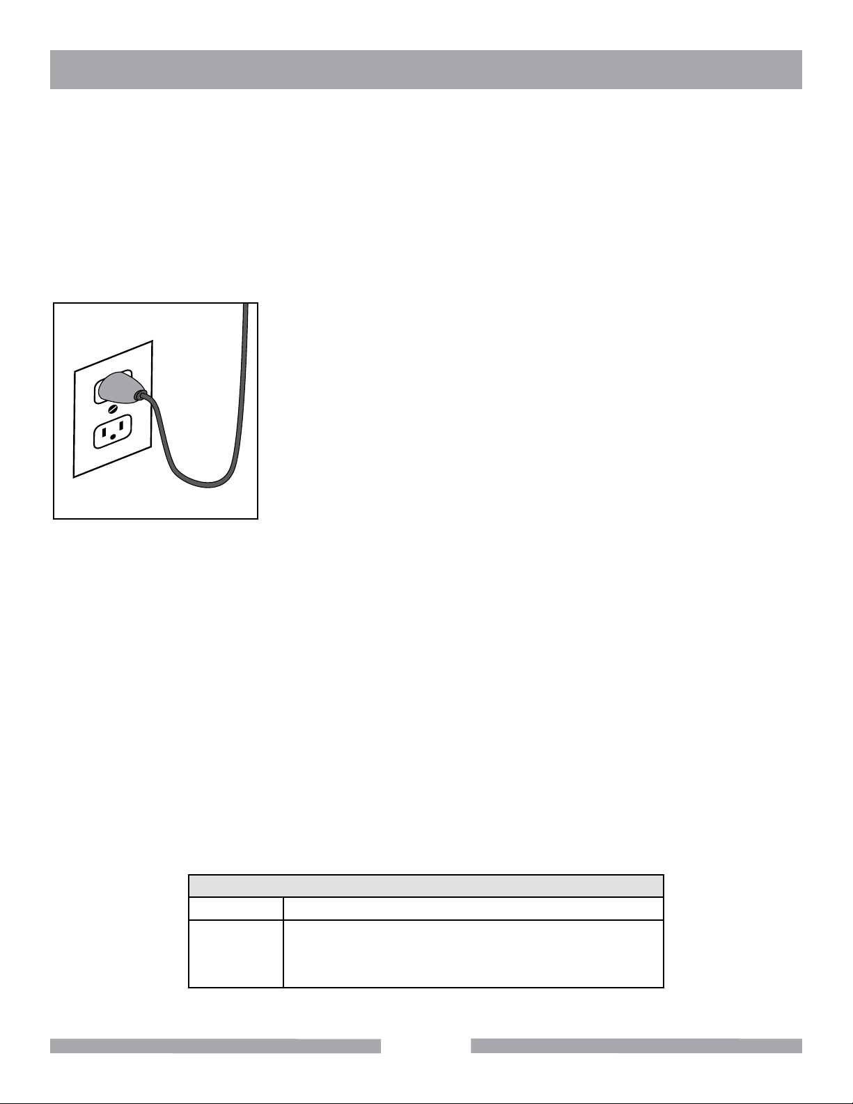
To avoid the possibility of the appliance plug or receptacle getting wet, position the tool to one side of
a wall mounted receptacle. This will prevent water from dripping onto the receptacle or plug. A “drip
loop," shown in illustration below, should be arranged by the user to properly position the power cord
relative to the power source.
The “drip loop" is the part of the cord below the level of the receptacle, or the connector, if an
extension cord is used. This method of positioning the cord prevents the travel of water along the
power cord and coming in contact with the receptacle.
If the plug or receptacle gets wet, DO NOT unplug the cord. Disconnect
the fuse or circuit breaker that supplies power to the tool. Then unplug
and examine for presence of water in the receptacle.
Use only extension cords that are intended for outdoor use. These
extension cords are identified by a marking “Acceptable for use with
outdoor appliances; store indoors while not in use." Use only extension
cords having an electrical rating not less than the rating of the product.
Do not use damaged extension cords. Examine extension cords before
Drip Loop
edges. Always disconnect the extension cord from the receptacle before disconnecting the product
from the extension cord.
using and replace if damaged. Do not abuse extension cords and do not
yank on any cord to disconnect. Keep cords away from heat and sharp
To reduce the risk of electrocution, keep all connections dry and off the ground. Don't touch the plug
with wet hands.
Use of undersized extension cords will result in low voltage to the motor that can result in motor
burnout and premature failure. Barranca Diamond warns that equipment returned to us showing signs
of being run in a low voltage condition, through the use of undersized extension cords, will be repaired
or replaced totally at the customer's expense. There will be no warranty claim.
To choose the proper extension cord:
• Locate the length of extension cord needed in table below.
• Once the proper length is found, move down the column to obtain the correct AWG size required for
that length of extension cord.
Extension Cord Minimum Gauge for Length
Volts Total Length of Cord in Feet
120 V 25 ft. 50 ft. 100 ft. 150 ft.
AWG AWG AWG AWG
14 12 Not Recommended
8
Page 9

SUPER CABMAKER GP8 SPECIFICATIONS
Weight: 115 lb s
Main Motor: Baldor
Horsepower: 1/2 HP
Motor Voltage/Frequency: 110 volt/60Hz
Amperage: 8.0 Amps
Motor RPM: 1,725 RPM Fixed
Motor Arbor Diameter: 1/2"
Duty: Continuous, automatic thermal protection shut off, manual
restart switch
Motor Arbor Bearings: Ball Bearings, permanently sealed
Shaft Bearings: Permanently sealed 1" OD shaft ball bearings fit into aluminum tank
and upper hood housing
Diamond Wheel Mesh Sizes: 80 and 170 mesh
Diamond Resin Belts: 400, 600, 1200, and 3000 mesh 8" x 3" wide belts
Expandable Rubber Drum: 8" x 3" wide x 1" arbor
Shaft Type: 21.31" precision machined stainless steel
Wheel and Blade Flanges: Aluminum 2" OD x 1" bore
Wheel Spacers: 1" ID aluminum (length varies for wheels and drum)
Convex Polishing End Hub: 8" aluminum hub disc with 1" - 14" left hand thread
Water Pump: MK Submersible pump (part #151271), variable flow control with 1/4"
ID tubing.
Flat Polishing End Hub: 8" aluminum hub disc with 1" - 14" left hand thread
Water Control Valves: 3 stainless steel control valves, brass lever cock valve with barb for
1/4" ID tubing mounted on rear of the hood
ON/OFF Switch Box: Lever operated switch box and pigtail female plug receptacle for
submersible pump
9
Page 10

SUPER CABMAKER GP8 SPECIFICATIONS
INCLUDED ACCESSORIES
Option 1 Part# 168077
• 1/2 HP thermal protected 1,725 RPM direct drive motor
• 80 & 170 grit 8" x 1-1/2" brazed metal-bond diamond wheels
• 400, 600, 1,200 & 3,000 grit 8" x 3" mesh resin-bond diamond belts
• 8,000, 14,000 & 50,000 grit polishing compound (individual 5 gram syringes)
• 8" x 3" rubber expandable drum
• Three 8" Polytex polishing pads
• 8" convex foam rubber lined aluminum polishing hub
• 8" leather polishing pad
• Carbide dressing stick
• 3M™ feathering disc adhesive
• Submersible water pump & hose
• Three stainless steel water control valves
• GFCI (110V motors only)
• Lightweight baseboard
Option 2 Part# 168077-FPS
• 1/2 HP thermal protected 1,725 RPM direct drive motor
• 80 & 170 grit 8" x 1-1/2" brazed metal-bond diamond wheels
• 400, 600, 1,200, & 3,000, grit 8" x 3" mesh resin-bond diamond belts
• 8,000, 14,000 & 50,000 grit polishing compound (individual 5 gram syringes)
• 8" x 3" rubber expandable drum
• Three 8” Polytex polishing pads
• 8" convex foam rubber lined aluminum polishing hub
• 8" flat aluminum hook & loop sanding and polishing hub
• Six 7" resin diamond polishing discs (220, 400, 800, 1,800, 3,500 & 8,500)
• Two 7" electroplated sanding discs (70 & 120 grit)
• 8" leather polishing pad
• Carbide dressing stick
• 3M™ feathering disc adhesive
• Submersible water pump & hose
• Three stainless steel water control valves
• Loc-Line magnetic manifold and nozzle links/tips
• GFCI (110V motors only)
• Lightweight baseboard
10
Page 11

SUPER CABMAKER GP8 SETUP
CONTENTS
In the shipping crate, you will find one Barranca Diamond GP-8 Super Cabmaker mounted to a plastic baseboard and one Ground Fault Circuit Interrupter (GFCI).
The accessories for the GP-8 Super Cabmaker will be included depending on which option you choose
(see page 10).
UNPACKING
Your GP-8 Super Cabmaker has been shipped from the factory thoroughly inspected and tested. Remove the
crating material (wood and plastic) from the baseboard and around the machine carefully using a Phillips and
standard screwdriver, wire cutter and box cutter knife. Any accessories should be removed from the unit and
put aside.
TRANSPORT
For safe transport, disconnect the submersible pump and power cord and remove lubricant and water from the
wheel reservoirs of the GP-8 Super Cabmaker.
11
Page 12

SUPER CABMAKER GP8 OPERATION AND ADJUSTMENT
PRE-START
Check all four motor mount bolts (Fig 3) to make sure they are tight.
Fig 1 - Front motor mount bolts
Fig 2 - GFCI
START-U P
Place the GP-8 Super Cabmaker on a strong flat table or bench. A power test can now be conducted
to make sure the motor is operating and all moving wheels and blades are correctly aligned and
secured to the main shaft. Plug the enclosed Ground Fault Circuit Interrupter (GFCI) into a 110 to 120
volt 60 Hz minimum 15 amp circuit wall outlet (Fig 2).
If needed, plug an extension cord into the GFCI. If an extension cord is used, refer to Table 1 on page
8 for the correct AWG size. The GP-8 Super Cabmaker power cord is attached to the ON/OFF switch
box on the right side of the unit. Make sure the switch box lever is in the OFF (Fig 3) position before
plugging into the GFCI or extension cord.
To energize and test the GFCI, push the RESET button (Fig 4) on the switch and a red window will
appear to indicate the switch is energized. If the TEST button is pushed, the switch will click off indicating the GFCI is functioning correctly. Push the reset button again to re-energize the GFCI.
Fig 3 - Power switch in the
OFF position
Fig 4 - GFCI reset button
12
Page 13

SUPER CABMAKER GP8 OPERATION AND ADJUSTMENT
The GP-8 Super Cabmaker is now ready for a power up test to be
performed. Turn the lever to the ON position (Fig 5) on the switch
box. Make sure no unusual sounds or vibrations occur when the
motor engages. If the motor coupling should loosen, use an allen
wrench to tighten the set screws. Liquid thread locker (removable
type) can be used on the setscrew threads to prevent loosening
during use.
PUMP SET-UP
A submersible electric water pump is used to supply water to the
polishing wheels as coolant and lubricant. It is recommended that
a 5 gallon bucket be used as a water reservoir into which the submersible pump should be placed. The level of the reservoir water
should be monitored so that water pump always remains fully submerged.
Fig 5 - Power switch in the ON
position
Fig 6 - Pump hose attached to water
pump outlet
Fig 7 - Water valve in the open
position
Fig 8 - Electrical outlet for
water pump
Connect the pump to the brass ON/OFF barbed lever valve at the rear of the hood with the included
1/4" ID water hose. Insert one end of the 1/4" ID water hose over the water pump outlet (Fig 6) and the
other end over the barbed end of the water valve inlet (Fig 6).
The pump can be plugged into the female receptacle plug accessory attached to the main switch box
(Fig 7) when using the GP-8 Super Cabmaker. Power to run the pump will occur once the switch box
lever is placed in the ON position. The pump should be operated in maximum flow setting. This will
allow sufficient water to reach the valve on the rear of the hood to provide water to each of the three
needle valves that control water flow to each of the three work stations.
Keep the water hose away from the electric motor and to prevent damage from moving parts and electric shock hazard. The pump should always be used with clear, clean water so as to avoid grit/abrasive
material, mud or rock fragments from scratching the gemstones during polishing or clogging the pump
valves. For optimal water flow, adjust both the pump and the brass intake valve to their fully open positions. Should less water be desired, turn the brass lever on the inlet valve to restrict flow to the hood
(Fig 8).
13
Page 14

SUPER CABMAKER GP8 OPERATION AND ADJUSTMENT
NEEDLE VALVES
The three stainless needle valves (Fig 9) are for fine control of water to each of the three grinding
and polishing stations. For best results, close the valves to the stations not in use. To shut off flow to
a needle valve, simply turn the grey ribbed knob clockwise until it closes to a firm stop (do not overtighten). To open maximum flow to a needle valve, simply turn the grey ribbed knob counterclockwise
until the valve stops. It may take up to 30 seconds for water flow rate to change to a specific station.
Fig 9 - The three stainless needle
valves
Fig 10 - Drain with hose installed
DRAIN
A length of 3/8" ID tubing is provided with the GP-8 Super Cabmaker for drainage of excess water
from the front base of the reservoir where a drain is located at the base of the reservoir (Fig 10).
To drain off the excess build-up of cooling water on the diamond wheels and expandable drum belts,
connect length of 3/8" ID clear tubing to the drain and route it into a 5 gallon collection bucket or drain
for dirty water.
Do not recycle dirty water from the drain valves into a collection bucket for pumping back up to the
intake valve on the rear of the hood as the contaminants (rock grit, mud, slurry and abrasive particles)
will likely scratch the gemstone material being worked and possibly clog the stainless steel water control valves or submersible pump.
DIAMOND WHEELS
The Diamond GP-8 Super Cabmaker comes equipped with two 8" OD x 1-1/2" brazed diamond
wheels in two diamond abrasive grit sizes (80 and 170 mesh or grit). Both wheels are manufactured to
a low tolerance OD circumference run-out for maximum wheel life and to prevent pounding and poor
performance during grinding. The high temperature brazed diamond bond provides excellent abrasive
performance when grinding the rough shape of the gemstone material. Diamond wheels must have an
uninterrupted flow of water during use for proper cooling and flushing of slurry and rock fragments.
A tool rest is attached to the reservoir base of the GP-8 Super Cabmaker in front of both the 80 and
170 grit diamond wheels (Fig 11). If a dop-stick is being used to hold the gemstone material, the user
can use the tool rest to securely hold the dop-stick while grinding, shaping and sanding. The tool rest
14
Page 15

SUPER CABMAKER GP8 OPERATION AND ADJUSTMENT
mount can be adjusted by loosening the positioning bolt (Fig 12), moving the tool rest to the desired
height, angle and/or distance from the wheel, and then retightening the positioning bolt. The tool rest
can also be completely removed (Fig 13) from the GP-8 Super Cabmaker base if the operator so desires.
Fig 11 - Tool rests Fig 12 - Tool rest positioning bolt Fig 13 - Grinding with tool rest
removed
Rough shaping of the gemstone material should be performed first with the 80-grit wheel with maximum water flow from the hood mounted water control valve. It is recommended that you only pump
clean water to the GP-8 Super Cabmaker water system and never recycle your drain water back to
your grinding wheels or expandable drum.
Due to the steel alloy core construction and brazed nickel diamond bounding of both wheels, a “ringing" noise will be heard during grinding and sanding. This is normal and should be of no concern.
Should coolant/flushing water flow be interrupted while grinding with the brazed diamond wheels, the
diamond may “glaze over" or dull the diamond bond. The diamond bond can be “dressed open" or
sharpened periodically by taking the green carbide stick and lightly touching it to the diamond grinding
face of the wheel while rotating (Fig 14). Only apply a slight pressure - for no more than 2 to 3 seconds
- with full flow of cooling water when “dressing open" the wheels. Do not over-sharpen as the wheel life
will be shortened. Never use the brazed diamond wheels dry under any circumstances.
Always ensure there is a clear, constant drip of water flowing off the rotating wheels into the reservoir
tank. Also, don’t over force the gemstone material into the diamond wheel surface while grinding. Allow the diamond bond on the wheel to work smoothly with a constant and steady application of hand
pressure. Rotate your gemstone frequently while grinding to uniformly remove material, nicks and flat
spots while rounding and contouring.
Remember, satisfactory results are dependent on the user's skill and experience, as well as the gemstone and equipment being used.
15
Page 16

SUPER CABMAKER GP8 OPERATION AND ADJUSTMENT
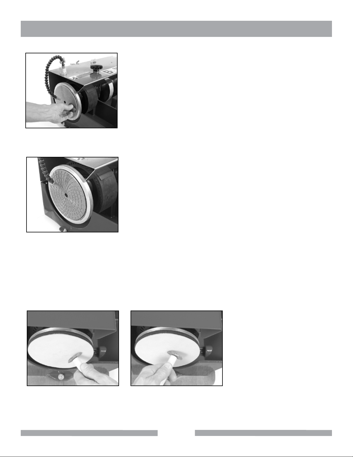
Fig 14 - Carbide stick applied to dia-
mond wheel
Fig 15 - Resin belt installed and cen-
tered on expandable drum
Fig 16 - Polytex pad being applied to
the convex polishing disc
EXPANDABLE DRUM AND DIAMOND RESIN BELTS
The GP-8 Super Cabmaker comes with four diamond resin belts (8“ OD x 3" wide) in abrasive grit
sizes: 400, 600, 1,200, and 3,000. These are to be placed over the edge and outer rim of the 8" x 3"
rubber expandable drum (Fig 15).
Be sure to center the diamond resin belt so that the width of the belt fits completely over the width
of the rubber drum. Once the GP-8 Super Cabmaker is turned on, the rotation of the shaft and rubber drum will cause the drum to expand outward, which will expand the rubber drum and tension the
belt on the drum. It is to be expected that the diamond resin belts will slide somewhat sideways while
sanding or polishing material. To safely and correctly use the belt, shut the unit off and reposition or
realign the belt over the drum and restart the unit.
Under no circumstances should the belts be used dry, as the build-up of heat from the grinding friction
with the gemstone material will cause the belts to wear out prematurely and possibly tear. Therefore,
keep a constant stream of water from the needle water control valve on the top of the hood (far left
valve) on at all times. Do not circulate dirty water from the reservoir tank or from a collection container
back into the water valves or else contaminant abrasive particles may scratch the gemstone. Always
pump from a clear and clean water reservoir to the diamond wheels and belts. For best results, always dry the gemstone material and check for scratches before proceeding to the next wheel or belt
diamond grit size. Do not skip belts in the four belt sequence (400, 600, 1,200, and 3,000 grit).
POLISHING WITH DIAMOND PASTE
The GP-8 Super Cabmaker comes with three syringes (5 grams each) of diamond paste in abrasive
grit sizes: 8,000, 14,000 and 50,000 mesh. These diamond pastes are to be used with the three 8"
OD Polytex polishing pads with adhesive backing on the foam covered convex 8" end polishing disc.
Once the gemstone material has been sanded and polished with the 3,000 grit diamond resin belt,
remove the paper backing on the Polytex pad to expose the adhesive surface, placing it firmly without
creases on the foam rubber convex surface of the 8" end polishing disc on the left side of the GP-8
Super Cabmaker (Fig 16).
Lightly smear with your fingertip a small amount of diamond paste on the center of the mounted Polytex pad with the unit operating and the polishing disc rotating. The diamond paste will evenly spread
over the surface of the Polytex pad once polishing of the gemstone starts. Move the gemstone in a
rocking and rotating motion from the center of the disc toward the outside edge to achieve a uniform
polished surface.
16
Page 17

SUPER CABMAKER GP8 OPERATION AND ADJUSTMENT
Use only one dedicated Polytex polishing pad with each respective diamond paste syringe (i.e. keep a labeled
Polytex pad for the 8,000 grit paste in a zip-lock bag labeled 8,000 grit). Do not use a single Polytex pad with
two or more diamond pastes or else cross-contamination and poor polishing of the gemstone material may
result.
The Polytex pad can be removed from the foam rubber covering of the convex polishing disc by slowly pulling the Polytex pad off the foam and placing it in a zip-lock plastic bag properly labeled with the syringe paste
diamond grit size for future use. No water or extender fluid is needed to effectively disperse the diamond paste
from the syringe to the Polytex pads. If the adhesive backing becomes weak with repeated use, you can apply
a few drops of 3M On/Off adhesive to improve the adhesive connection to the foam disc.
SANDING AND POLISHING FLAT (7" DISCS) Option 2 (Accessories)
GP8 Supercabmaker employs an 8" end of shaft aluminum faced hook
lined flat polishing system that mounts on the left hand end of the main
arbor shaft. User will have to first remove the convex rubber faced aluminum disc (left hand thread, rotate disc clockwise to loosen and remove).
Once removed, thread on the flat faced hook lined 8" aluminum flat
sanding/polishing disc which will act as a backer mounting disc to the 7"
electroplated sanding pads and 7" resin diamond polishing pads (Fig 17).
A LockLine manifold (magnetic base) and flexible nozzle line system
must be used in with these 7" sanding and polishing pads to direct cool-
Fig 17 - Accessories Option 2
ing/flushing water in a mist spray onto the electroplated and resin dimond
surfaces mounted vertically with hook & loop on the aluminum flat faced
disc (Fig 18).
Fig 18 - LockLine & Nozzle connected
Fig 19 - Connection tube and valve
The LockLine magnetic base mounted nozzle will need to be attached
with 3/8" OD x 1/4" ID clear plastic tubing to the submersible water pump
placed in a 5 gallon bucket to provide a supply of clean cooling water (do
not recycle dirty water to the LockLine system). The clear water feed tubing will connect to the LockLine manifold at a brass barb fitting (Fig 29).
Water flow is controlled by adjusting the plastic knob on the LockLine
flexible line so that a fine mist is dispensed onto the center face of the 7"
electroplated and resin diamond polishing pads.
To use 7" sanding electroplated diamond pads (70 and 120 grit), first
mount the pad centered over the hook lined flat aluminum disc, position
the LockLine nozzle to center of the pad and turn on the GP8 main power
switch. The submersible pump will need to be plugged into the accessory receptacle (female) on the On/Off switch box. After a few seconds,
the pump will deliver water through the feed clear tubing to the LockLine
manifold and flexible nozzle where the spray mist can be regulated. Only
a fine mist is required to flush and cool the electroplated pads while
sanding saw and grinding marks out of a gemstone specimen. Move
the specimen face to be sanding slowly across the lower 1/2 face of the
electroplated pad (70 grit) and periodically inspect the gemstone face by
drying to determine whether the saw and or grinding marks have been
sufficiently removed (Fig 20).
17
Page 18
SUPER CABMAKER GP8 OPERATION AND ADJUSTMENT
Once the majority of coarse saw and grinding marks have been sanded
off with the 70 grit electroplated pad, the user can replace the 70 grit pad
with the 120 grit electroplated pad and repeat the process to sand flat all
visible saw or grinding marks or uneven surfaces. Dry off gemstone and
inspect closely.
Upon satisfactory sanding of the gemstone with 70 and 120 grit 7" electroplated discs, mount the red 220 grit 7" resin diamond polishing pad
centered flat aluminum disc and proceed to polishing the gemstone
across the lower face of the pad inspecting the face surface frequently
(Fig 23). Progress through the 400, 800, 1,800, 3,500, and 8,500 grit 7"
Fig 20 - Sanding gemstone
resin diamond polishing pads, making sure to closely inspect the gemstone surface closely before proceeding to the next finer (higher num-
bered sequence) resin diamond pads. In some cases, stubborn scratches or uneven portions of the gemstone face being worked will need to be
polished with a lower (coarser) grit resin diamond pad therefore the user
is advised to closely inspect the face of his gemstone dry and to retreat
back a grit size or lower if necessary. Never skip a grit size when polishing.
Fig 21 - Polishing pad centered on
flat aluminum disc
POLISHING WITH THE LEATHER BUFF PAD
For final polished gemstone results, place the 8" cowhide leather pad (rough side out) on the foam polishing
end disc using the 3M On/Off adhesive (red box) to hold the leather pad securely while buffing the gemstone in
a rocking motion (Figs 22 & 23). Only use a small amount (8 to 10 dabs) of 3M On/Off adhesive on the smooth
cowhide surface, smearing it uniformly before placing it over the foam rubber on the polishing disc. When the
final polish finish of your gemstone
has been achieved, remove the
leather disc and place it in a zip-lock
bag to protect it for future use. It is
not necessary to use any polishing
media or liquid (water) when buffing
the gemstone with the leather disc.
Be sure to firmly grip the gemstone
by hand or with a dop-stick (wood
dowel or aluminum rod) cemented or
epoxied to the back of the gemstone
while using the leather buff pad.
Fig 22 Fig 23
18
Page 19

SUPER CABMAKER GP8 OPERATION AND ADJUSTMENT
DIAMOND WHEEL/CARBIDE WHEEL REPLACEMENT
When worn-out, the diamond wheels and expandable drum can be removed and replaced. For all models,
first prepare the arbor shaft for removal from the body of the GP-8.
1. Unscrew and remove the locking knobs from the hood (Fig 24).
2. Rotate the hinged hood back completely (Fig 25).
3. Using an allen wrench, loosen set screws on the main arbor 1" to motor arbor 1/2" coupler (Fig 26).
4. Once coupler set screws are loosened, lift up arbor assembly and remove (Fig 27).
5. Loosen jam nut on left end of arbor shaft once convex or flat 8" disc is removed (left hand thread).
6. Slide off & remove aluminum flanges and spacers against rubber drum.
7. Use allen wrench to loosen and remove collars mounted to sealed bearings.
8. Slide off bearings, spacers and flanges on metal bond grinding wheels to remove and replace as needed.
Fig 24 - Remove the locking knobs Fig 25 - GP-8 Super Cabmaker with
hood rotated back
Fig 27 - Arbor Assembly
Fig 26 - Use an allen wrench to re-
move collars
19
Page 20
SUPER CABMAKER GP8 MAINTENANCE
SHAFT REASSEMBLY
Reassembly of the shaft with the new diamond wheels is the reverse of the disassembly instructions. Please
keep the following points in mind when reassembling:
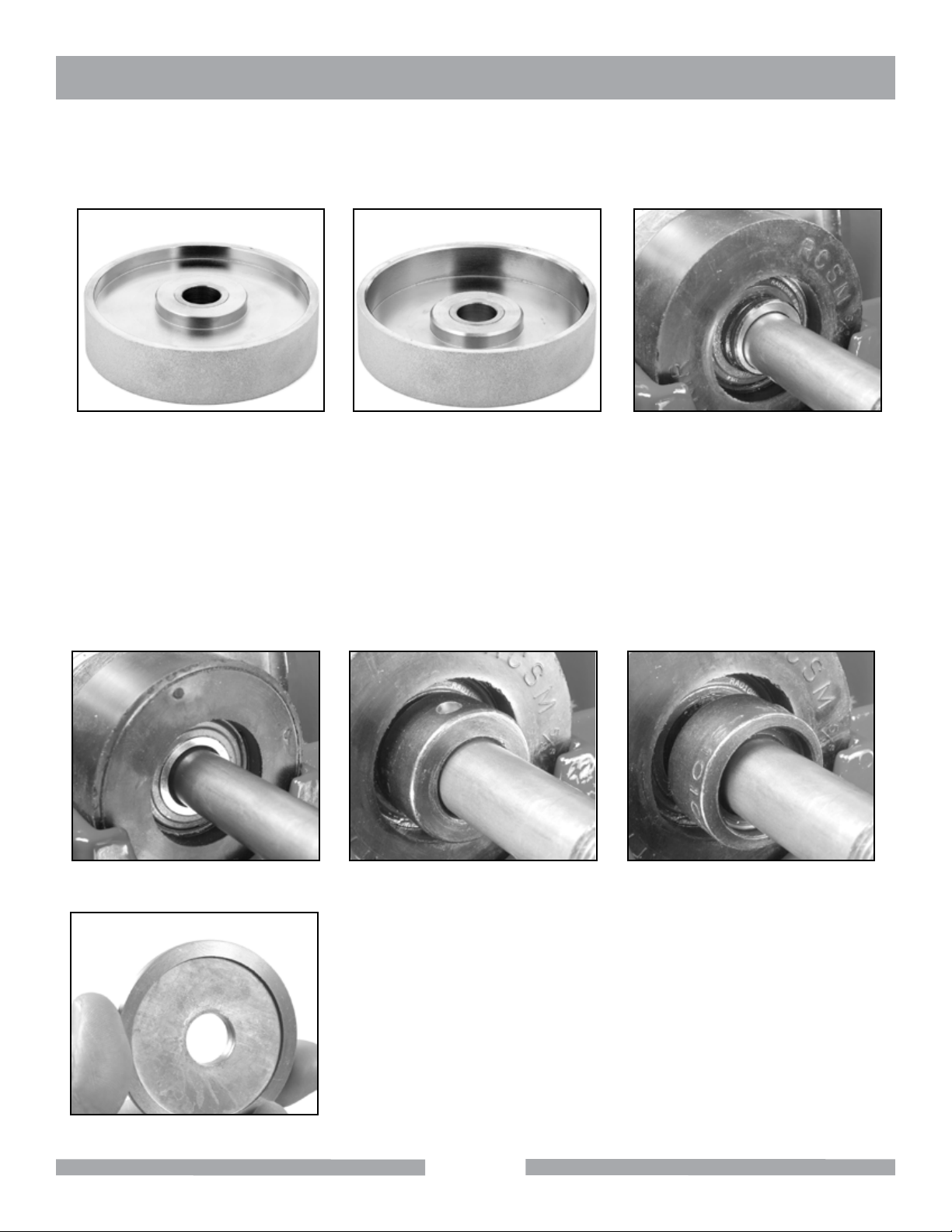
Fig 28 - Outside face of diamond
wheel
Fig 29 - Inside face of diamond Fig 30 - Bearing correctly installed
1. Install diamond wheels with the inside faces facing each other (Fig 28 & 29). Be sure the diamond wheel
bushings are installed.
2. The bearings have a permanently mounted bushing that extends from one side of the center bearing. This
extension must face away from the diamond wheels (Fig 30 & 31) on both ends of the arbor shaft.
3. The arbor shaft collars have one recessed side and one flat side (Fig 32 & 33). The recessed side should
face the bearing and mate against the extended portion of the bearing bushing.
4. There should be a flange installed on both sides of each diamond wheel and the expandable drum. Make
sure the concave side of the flange (Fig 34) faces the wheels and drum.
Fig 31 - Bearing incorrectly installed Fig 32 - Bearing collar correctly
installed
Fig 33 - Bearing collar incorrectly
installed
Fig 34 - Concave side of flange
20
Page 21

SUPER CABMAKER GP8 MAINTENANCE
Fig 35 - Bearing correctly seated Fig 36 - Bearing incorrectly seated
5. When installing the shaft assembly back in the GP-8 Super Cabmaker, make sure the rubber mounted
bearings are centered in the bearing seat (Fig 35 & 36). If the bearings are not centered in the bearing
seats make sure the aluminum spacers are in the correct order and that the bearings and arbor collars are
properly installed.
6. Install the sanding drum with arrow of rotation facing direction of rotation (Fig 37).
7. Make sure grinding wheel and drum bushings are installed.
8. Remount arbor assembly in gate reservoir, tighten coupling set screws, close hood and retighten the two
locking knobs (Fig 38).
Fig 37 - Arrow on drum indicates
direction of rotation
Fig 38 - GP8 Unscrew the Cabmaker
21
Page 22
SUPER CABMAKER GP8 MAINTENANCE
ARBOR ASSEMBLY
The GP-8 Super Cabmaker is equipped with a 1" OD arbor shaft, two rubber sealed ball bearings and a shaft
1" to motor arbor 1/2" coupler (Fig 39). Should the bearings wear out on the arbor shaft, grinding and polishing
performance and short diamond wheel/belt life may result. Additionally, premature bearing wear may result in
permanent damage to the arbor shaft, and motor. This main stainless steel shaft arbor assembly can be purchased from Barranca Diamond as a complete unit. Periodically check the tightness of the hood attachment
knobs (Fig 40) to make sure they are securely tightened to the aluminum reservoir body of the GP-8 Super
Cabmaker.
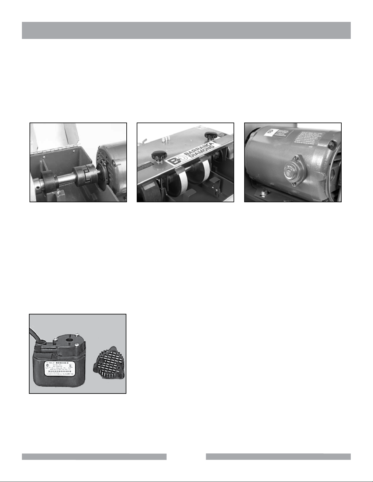
Fig 39 - Shaft to motor arbor coupler Fig 40 - Hood attachment knobs Fig 41 - Motor reset button
ELECTRIC MOTOR
The GP-8 Super Cabmaker is equipped with a Baldor 1/2 HP 1725 RPM single-phase 120 volt 60 Hz 8 amp
motor. The motor shaft has sealed ball bearings and requires no lubrication. The motor is protected from thermal damage (overheating) with an automatic shut-off switch. If the motor overheats it will automatically shut off
and restart once its internal components cool down and the motor is restarted manually (red button). Be sure
to shut off the main motor by placing the switch lever to the OFF position and disconnecting the power source.
After allowing the motor to cool (2 to 3 hours), push the red reset button on the side of the motor (Fig 41) and
restart the unit by turning the switch to ON. If the motor does not restart after a cool down period, remove the
motor and have an authorized repair service center for Baldor inspect the motor. Barranca Diamond can refer
you to an authorized motor repair service center in your area.
SUBMERSIBLE PUMP
Periodically remove the plastic inlet cover on the submersible water
pump (Fig 42). Remove the outside plastic filter and clean any obstructions such as sludge or rock mud that may be found. Clean the filter with
warm, soapy water. Replace the filter and test the pump to ensure it is
functioning properly.
Fig 42 - Water Pump
22
Page 23

NOTES
23
Page 24

SUPER CABMAKER GP8 EXPLODED VIEW
24
Page 25

SUPER CABMAKER GP8 PARTS LIST
ITEM DESCRIPTION PART # QTY
1 PAD, POLISHING 8" POLYTEX 1409 3
2 PAD, POLISHING 8" LEATHER 14622 1
3 HOSE, VINYL, 1/4 X 3/8 TSAW 132951 1
4 WASHER, 3/8 SAE FLAT 150923 4
5 SCREW, SOC HD CAP, 1/4 - 20 X 1 151049 4
6 PUMP, WATER, G - 150A 151271 1
7 WASHER, FLAT, SAE 5/16 151754 4
8 NUT, HEX, 1/4 - 20 151893 4
9 WASHER, 1/4 SAE FLAT 151915 11
10 GFCI, 120V, 15A 152610 1
11 SCREW, HEX, 3/8 - 16 X 3/4 153527 4
12 CARTON 10 X 9 - 3/16 X 4 153737 1
13 SCREW, 5/16 - 18 X 5/8 HEX HEAD CAP 153949 4
14 HOSE, WATER VINYL 3/8 X 1/2 156039 1
15 NUT, HEX `10 - 32 156269 3
16 TAG, SERIAL NUMBER, BLANK 157500-RW 1
17 DRIVE SCREW, #7 X 5/16 ROUND HEAD 157849 2
18 FEATHERING DISC ADHESIVE 161323 1
19 BEARING, 1" W COLLAR, RUBBER 161347 2
20 BRACKET, TOOL REST LH 1614 42 1
21 CROSS, #10 - 32 161532 1
22 FLAP, WHEEL 161557 3
23 KNOB, 3/8 - 16 161651 2
24 KNOB, RIDGED, GRAY 161652 3
25 NUT, 1 - 14 LH, THIN HEX 161713 1
26 OIL, TOOL COOL, 8 OX. 16172 9 1
27 POLISHING COMPOUND, 01 MICRON 161766 1
28 POLISHING COMPOUND, 02 MICRON 161767 1
29 POLISHING COMPOUND, 03 MICRON 16176 8 1
30 SCREW, PAN HEAD PHILLIPS 10 - 32 X 3/8" 161875 4
31 VALVE, 10/32 161989 3
32 ADAPTOR, MALE PIPE 1/8 NPTF 161991 2
33 VALVE, 1/8 NPTFM X 1/4 TUBE 1619 92 1
34 DISC 8" SPONGE RUBBER 162046 1
35 BRACKET, HOSE MOUNT 162154 3
36 CASTING, POLISHING PAD 162190 1
37 COLLAR, 1" SHAFT X 1-1/2" 162310 1
38 ADAPTOR, MALE PIPE 1/8 NPTF 162315 1
39 TUBING, CLEAR PVC, 1/8 X 1/4 162505 1
40 CLIP, HOSE RETAINER 162 511 1
41 SCREW, 1/4 - 20 X 1/2 SOCKET HEAD CAP 162778 7
42 BRACKET, TOOL REST RH 166439 1
25
Page 26

SUPER CABMAKER GP8 PARTS LIST
ITEM DESCRIPTION PART # QTY
43 WELDMENT, HOOD 168075 1
44 SHAFT, DRIVE 168076 1
45 TOOL REST 168080 2
46 ROD, THREADED 168082 1
47 MOUNTING BASE 168109 1
48 SPACER 168114-01 1
49 SPACER 168114-02 1
50 SPACER 168114-03 1
51 SPACER 168114-04 1
52 SPACER 168114-05 1
53 SWITCH ASSEMBLY 168116-01 1
54 TANK, COMP. 168153 1
55 HUB, COUPLING 1/2" 168179 1
56 HUB, COUPLING 1" 168180 1
57 SPIDER, COUPLING 168181 1
58 FLANGE, OUTER, 2-3/8 168440 6
59 BD LOGO LABEL 168448 1
60 MOTOR 1/2 HP 168504 1
61 OWNER'S MANUAL 168687 1
62 BOX, WOOD, SHIPPING GP-8 168725 1
63 DRUM, 8 X 3 EXPANDING RUBBER 390008 1
64 BELT, RESIN 8 X 3 1200 GRIT 398121 1
65 BELT, RESIN 8 X 3 3000 GRIT 398300 1
66 BELT, RESIN 8 X 3 400 GRIT 398400 1
67 BELT, RESIN 8 X 3 600 GRIT 398600 1
68 WHEEL, BRAZED 80 498080 1
69 WHEEL, BRAZED 170 498200 1
70 DRESSING STICK, GREEN 999997 1
26
Page 27

NOTES
27
Page 28

NOTES
28
Page 29

CAB COMBO WARRANTY
Barranca DiamonD LimiteD Warranty
Please complete the warranty registration card and return. Any problems encountered should be directed to
Barranca Diamond Customer Service department at (800) 630-7682 M-F 8am - 5pm PST.
NOTE THIS INFORMATION FOR FUTURE USE:
MODEL NUMBER:
SERIAL NUMBER:
PURCHASE PLACE:
PURCHASE DATE:
Barranca Diamond warrants to the original retail purchaser for a period of 1 year except as noted, from the
date of purchase all products covered by this Warranty to be free of defects in materials and workmanship.
This Warranty shall not apply to any parts that have been subjected to misuse or improper service, that had
been damaged in transit or handling, or that have been altered or repaired by unauthorized representatives.
This Warranty does not cover defects caused by or resulting from misuse, abuse, neglect or damage caused
by accident or the failure to provide reasonable maintenance. This Warranty is void if the product or any of its
individual components is altered or modied by the purchaser or if the product is used in a manner or with a
blade not recommended by the manufacturer.
Any claim arising under this Warranty must be submitted by the original purchaser within the warranty period
specied above, and shall include proof of purchase. During said warranty period Barranca Diamond shall,
at its option, either replace or repair, at no charge to the original purchaser, any parts or components that are
found to be defective by Barranca Diamond. Barranca Diamond shall not be responsible for or obligated to
pay for freight or other transportation related costs or expenses in connection with any defective products or
components that are either returned to Barranca Diamond’s facility or any authorized repair station and/or any
replacement products or components that are shipped from Barranca Diamond pursuant to this Warranty.
Parts and labor needed to maintain products and the replacement of components due to normal wear and tear
are the purchaser’s responsibility and are not covered by this Warranty. All products or components replaced
under warranty become the property of the manufacturer. All replacement parts will be considered to be part
of the original product and any warranty on such parts will expire coincidentally with the original Warranty.
Barranca Diamond will pay for parts and labor in connection with warranty repairs conducted by Barranca Diamond or its authorized repair centers. Replacement part(s) installed by anyone else will be provided without a
charge for such replacement part(s), but this Warranty will not apply to labor charges in connection therewith.
IN NO EVENT SHALL ANY LIABILITY UNDER THIS WARRANTY EXCEED THE REPLACEMENT COST OF
ANY DEFECTIVE PRODUCT OR COMPONENT THEREOF, AND BARRANCA DIAMOND SHALL NOT BE LIABLE FOR ANY INCIDENTAL OR CONSEQUENTIAL DAMAGES OR FOR ANY OTHER DAMAGE OR LOSS
NOT EXPRESSLY ASSUMED AS SET FORTH HEREIN.
The foregoing constitutes an expressed warranty on the terms set forth above and is the only warranty or
warranties applicable to the products it covers. All other warranties, including, without limitation, the implied
warranty of merchantability and/or tness for a particular purpose or use being denied. This limited warranty is
expressly in lieu of all other warranties, whether expressed or implied.
29
Page 30

CAB COMBO WARRANTY
Specics Applicable to Limited Warranty of Diamond Blades and Core Bits:
Laser Welded Blade and Bit Warranty:
If the laser weld between the segment and the steel core or barrel fails during normal use, the blade
or bit will be replaced free of charge. Blades and bits damaged due to careless or improper use are
not covered under this warranty.
Brazed Blade, Bit, and Cup Wheel Warranty:
If the brazed bond between the segment and the core, barrel, or cup fails within the rst .050 of segment wear, the blade, bit, or cup will be replaced free of charge. Blades, bits, and cup wheels damaged due to careless or improper use are not covered under this warranty.
Continuous Rim Blade Warranty:
If the bond between the rim and the core fails during normal use, the blade will be replaced free of
charge. Blades and bits damaged due to careless or improper use are not covered under this warranty.
Exclusions:
Barranca Diamond does not warrant the following components, which carry their own manufacturer’s
warranty for the indicated periods:
Electric Motors Manufacturer’s Warranty
Baldor: 1 year
Ryobi: 1 Year
Soga: 1 Year
Gas Engines Manufacturer’s Warranty
Honda: 2 years
Engine Power Information
Engine power ratings are calculated by the individual engine manufacturer and the rating method
may vary among engine manufacturers. Barranca Diamond Products makes no claim, representation
or Warranty as to the power rating of the engine on this equipment and disclaims any responsibility
or liability of any kind whatsoever with respect to the accuracy or the engine power rating. Users are
advised to consult the engine manufacturer’s owner's manual and website for specic information
regarding the engine power rating.
30
Page 31

CAB COMBO WARRANTY
rePLacement PartS
Replacement parts for this tool may be ordered from your Barranca Diamond distributor or directly from
Barranca Diamond. Please have the following information ready before calling:
• Model and serial number of the machine
• Date of purchase
• Description of parts being ordered (see parts list)
retUrn materiaLS ProceDUre
To expedite the service relative to the return of a product purchased through Barranca Diamond, please have
the following information available:
• Model and serial number of the machine
• Date of purchase
• Distributor’s name
Then please call Barranca Diamond at (310) 523-5867 or toll free at 800-630-7682 to obtain a Return Goods
Authorization number (RGA) authorizing the return.
Please Note:
• Ensure your item(s) are prepaid to the destination
• Return items must have been purchased within the previous twelve (12) months
• Follow the packaging instructions in the following section
• Be sure to include the RGA number, return address and your phone number on or within the
return shipping box.
PacKaGinG inStrUctionS
Ship the equipment using its original shipping crate if possible. Secure inside the shipping crate. Ensure all
parts are secured in the packaging to prevent movement. Do not ship the equipment partially exposed.
31
Page 32

Barranca Diamond Products, Inc.
22815 Frampton Avenue
Torrance, CA 90501
Toll-Free: (800) 630-7682
Phone: (310) 523-5867
Fax: (310) 257-3063
www.barrancadiamond.com
 Loading...