

Page 1
GP-6 Cabmaker
Owner’s Manual and Operating Instructions
Belts Model: Part# 8300048
Diamond Pads Model: Part# 8300052
Carbide Wheel Model: Part# 8300046
Revision 104 04.2013
Manual Part No. 165967
Caution: Read all safety and
operating instructions before using
this equipment. This manual MUST
accompany the equipment at all times.
Barranca Diamond Products, Inc.
1315 Storm Parkway
Torrance, CA 90501
Toll-Free: (800) 630-7682
Phone: (310) 523-5867
Fax: (310) 257-3063
www.barrancadiamond.com
Page 2

TABLE OF CONTENTS
Thank you for selecting the Barranca Diamond GP-6 Cabmaker. We are certain that you will be
pleased with your purchase. Barranca Diamond takes pride in producing top quality products for hobbyists and commercial
lapidary users throughout the world. This product is manufactured in the United States.
This owner’s manual contains information necessary to operate and maintain your GP-6 Cabmaker
safely and correctly. Operated correctly, the GP-6 Cabmaker should provide you with years of service.
Please take the time to familiarize yourself with the GP-6 Cabmaker by reading and reviewing this
manual.
If you should have questions concerning your GP-6 Cabmaker, please call Barranca Diamond at:
(310) 523-5867 or Toll Free: (800) 630-7682.
TABLE OF CONTENTS
SAFETY
Safety Precautions 3
California Proposition 65 Warning 6
Electrical Requirements 7
GP-6 SPECIFICATIONS 9
SETUP
Contents 10
Unpacking 10
Installation of Rubber Feet 10
Transport 10
OPERATION AND ADJUSTMENT
Pre -S t ar t 11
Start-Up 12
Pump Set-Up 13-14
Needle Valves 14
Drain Valves 14
Diamond Wheels 15-16
Expandable Drum & Resin Belts 16
Polishing with Diamond Paste 17
Polishing with Leather Buff Pad 18
GP-6 Cabmaker Pads Model 19
Setup of GP-6 (Pads) Loc Line System 19
Use of 5" Diamond Resin Pads 20
MAINTENANCE
Grinding Wheel Replacement 21
Shaft Reassembly 22-25
Belt 26
Arbor Assembly 26
Electric Motor 26-27
Submersible Pump 27
PARTS LIST
Parts List 28-36
WARRANTY 37
CUSTOMER SERVICE
Replacement Parts 38
Returns 39
Packaging Instructions 39
2
Page 3

GP-6 CABMAKER SAFETY
SAFETY PRECAUTIONS
Read and follow all safety, operating and maintenance instructions. Failure to read and follow
these instructions could result in injury or death to you or others. Failure to read and follow these
instructions could also result in damage and/or reduced equipment life. In order to prevent injury, the
following safety precautions should be followed at all times!
READ OWNER'S MANUAL BEFORE USE
Before using this equipment, ensure that the person operating this machine reads and understands
all of the instructions in the manual. Precaution is the best insurance against accidents. Read and
understand all safety precautions, messages, warnings and hazard symbols. You are responsible for
your own safety.
ALWAYS USE SAFETY GLASSES
Safety glasses should always be worn when working around power tools. In addition, a face, dust
mask or respirator should be worn if a cutting operation is dusty. Everyday eyeglasses only have
impact resistant lenses and may not prevent eye injury - they are NOT safety glasses.
USE PROPER APPAREL
Do not wear loose clothing, gloves, neckties, rings, bracelets or other jewelry that may be caught
in moving parts. Non-slip footwear is recommended. Wear protective hair covering to contain long
hair. Hand protection (plastic gloves) and a shop bib are recommended during use to prevent stains
to clothing. Do not touch the work material until the motor is off and the machine has come to a
complete stop.
ALWAYS USE HEARING PROTECTION
To reduce the possibility of hearing loss, always use hearing protection when operating power
equipment.
ELECTRICAL SHOCK
Never touch electrical wires or motor components while the motor is running. Exposed, frayed or worn
electrical wiring and plugs can be sources of electrical shock that could cause severe injury or burns.
Use a GFCI (Ground Fault Circuit Interrupter) attached to the main motor power cord plug and keep
plugged into the power receptacle outlet source.
DISCONNECT TOOLS
Power tools should always be disconnected before servicing or when changing accessories, such as
blades, bits, cutters and the like.
REDUCE THE RISK OF UNINTENTIONAL STARTS
Make sure the ON/OFF switch is in the OFF position before plugging in a power tool.
ROTATING OR MOVING PARTS
Keep hands, feet, hair, and clothing away from all moving parts to prevent injury. Never operate the
engine with covers, shrouds or guards removed.
3
Page 4

GP-6 CABMAKER SAFETY
MAINTAIN TOOLS WITH CARE
Keep tools clean for the best and safest performance. Always follow maintenance instructions for
lubricating and when changing accessories.
KEEP WORK AREA CLEAN
Cluttered work areas and benches invite accidents.
DO NOT USE IN DANGEROUS OR HAZARDOUS ENVIRONMENTS
Do not operate equipment in dangerous or hazardous environments. Do not use power tools in damp
or wet locations nor expose them to rain. Always keep the work area well lighted. Always work in a
well ventilated area.
REMOVE ADJUSTING KEYS AND WRENCHES
Form a habit of checking to see that keys, tools, rock material and adjusting wrenches are removed
from the Cab Combo Workshop before plugging in the power cord and operating the unit.
KEEP CHILDREN AWAY
All visitors and children should be kept a safe distance from the work area. Keep power cords
disconnected when tool is not in use.
MAKE THE WORKSHOP KID-PROOF
Make the workshops kid-proof by using padlocks, master switches and by disconnecting all power
cords.
USE THE RIGHT TOOL
Do not force a tool or an attachment to do a job that it was not designed to do.
SECURE WORK
Clamps or a vise should be used to hold work whenever practical. Keeping your hands free to operate
a power tool is safer.
DO NOT OVERREACH
Keep proper footing and balance at all times by not overreaching.
MAINTAIN TOOLS WITH CARE
Keep the diamond tools in good condition by replacing coolant water and cleaning the reservoir
frequently for the best and safest performance. Always follow the maintenance instructions for
servicing the unit.
SHUTDOWN OF THE UNIT
The machine should always be shutdown (ON/OFF switch placed in the OFF position) and the power
cord disconnected to the power source before servicing or when changing accessories.
4
Page 5

GP-6 CABMAKER SAFETY
NEVER LEAVE A TOOL RUNNING UNATTENDED – TURN POWER OFF
Do not leave a tool until it comes to a complete stop. Always turn the tool off, and disconnect the
power cord from its source. Do not leave extension cords attached to the power cord or power
receptacle (wall outlet) when leaving the work area.
CHECK FOR DAMAGED OR WORN PARTS
Before using a power tool, check for damaged parts. Always check moving parts for proper alignment
or binding. Check for broken parts and mountings and all other conditions that may affect the
operation of the power tool. Any damaged part, should be properly repaired or replaced.
USE RECOMMENDED ACCESSORIES AND PARTS
Consult the owner’s manual for recommended accessories and parts. Using improper parts and
accessories may increase the risk of personal and/or bystander injury.
USE THE PROPER EXTENSION CORD
If using an extension cord, make sure it is in good condition first. When using an extension cord, be
sure to use one heavy enough to carry the current your product will draw. An undersized cord will
cause a drop in line voltage that will result in a loss of power and overheating. TABLE 1, shows the
correct AWG (American Wire Gauge) size to use depending on cord length and nameplate ampere
rating. If in doubt, use the next heavier gauge. The smaller the gauge number, the heavier the cord.
USE A GROUND FAULT CIRCUIT INTERRUPTER
Use of a Ground Fault Circuit Interrupter (GFCI) between the end of power cord and wall outlet is
required at all times.
USE THE PROPER POWER SOURCE
This tool is only to be used with a 120 volt 60 HZ power source. Ensure power source is at least 15
amps and 110 to 120 volts. Low voltage current can adversely effect electric motor performance and
overall life.
USE THE RECOMMENDED COOLING AND LUBRICATING FLUIDS
Never operate a tool dry that requires coolant or lubricant. This can lead to shortened tool life, tool
damage and personal injury.
MAINTAIN TOOLS WITH CARE
Always follow the maintenance instructions for servicing the GP-6 Cabmaker.
5
Page 6

GP-6 CABMAKER SAFETY
ON
(
(
)
)
SILICA DUST WARNING
Grinding/cutting/drilling of masonry, concrete, metal and other materials with silica in their composition
may give off dust or mists containing crystalline silica. Silica is a basic component of sand, quartz,
brick clay, granite and numerous other minerals and rocks. Repeated and/or substantial inhalation of
airborne crystalline silica can cause serious or fatal respiratory diseases, including silicosis. In addition, California and some other authorities have listed respirable crystalline silica as a substance
known to cause cancer. When cutting such materials, always follow respiratory precautions.
Use appropriate NIOSH-approved respiratory protection where dust hazard may occur. Paper masks
or surgical masks without a NIOSH approval number are not recommended because they do little to
protect the worker. For more information about respirator programs, including what respirators have
received NIOSH approval as safe and effective, please visit the NIOSH website at:
http://www.cdc.gov/niosh/topics/respirators
Observe OSHA regulations for respirator use (29 C.F.R.§1910.134 and §1503.1).
Visit http://www.osha.gov for more information.
CALIFORNIA PROPOSITION 65 MESSAGE
Some dust created by power sanding, sawing, grinding, drilling, and other construction activities contain chemicals known (to the State of California) to cause cancer, birth defects or other reproductive
harm. Some examples of these chemicals are:
• Lead, from lead-based paints
• Crystalline silica from bricks, cement and other masonry products
• Arsenic and chromium, from chemically treated lumber
For further information, consult the following sources:
http://www.osha.gov/dsg/topics/silicacrystalline/index.html
http://www.cdc.gov/niosh/docs/96-112/
http://oehha.ca.gov/prop65/law/P65law72003.html
http://www.dir.ca.gov/Title8/sub4.html
Your risk from these exposures varies depending on how often you do this type of work. To reduce
your exposure to these chemicals, work in a well-ventilated area, and work with approved safety
equipment, such as the dust masks that are specially designed to lter out microscopic particles.
Where use of a dust extraction device is possible, it should be used. To achieve a high level of dust
collection, use an industrial vacuum cleaner.
WARNING
Sawing and drilling generate dust. Excessive airborne particles may cause irritation to eyes, skin and
respiratory tract. To avoid breathing impairment, always employ dust controls and protection suitable
to the material being sawed or drilled; See OSHA (29 CFR Part 1910.1200).
6
Page 7
GP-6 CABMAKER SAFETY
ELECTRICAL REQUIREMENTS AND GROUNDING INSTRUCTIONS
In order to prevent potential electrical shock and injury, the following electrical safety precautions and
symbols should be followed at all times!
In case of a malfunction or breakdown, grounding provides a path of least resistance for electric
current to reduce the risk of electric shock. This tool is equipped with an electric cord having an
equipment-grounding conductor and a grounding plug. The plug must be plugged into a matching
outlet that is properly installed and grounded in accordance with all local codes and ordinances.
• Do not modify the plug provided – if it will not fit the outlet, have the proper outlet installed by a
qualified electrician.
• Improper connections of the equipment-grounding conductor can result in a risk of electric shock.
The equipment-grounding conductor is the wire that has a green outer surface, with or without
yellow stripes. If repair or replacement of the electric cord or plug is necessary, do not connect the
equipment-grounding conductor to a live terminal.
• Check with a qualified electrician or service personnel if the grounding instructions are not
completely understood, or if in doubt as to whether the tool is properly grounded.
• Use only 3-wire extension cords that have 3-prong grounding plugs and 3-pole receptacles that
accept the tool’s plug.
• Repair or replace a damaged or worn cord immediately.
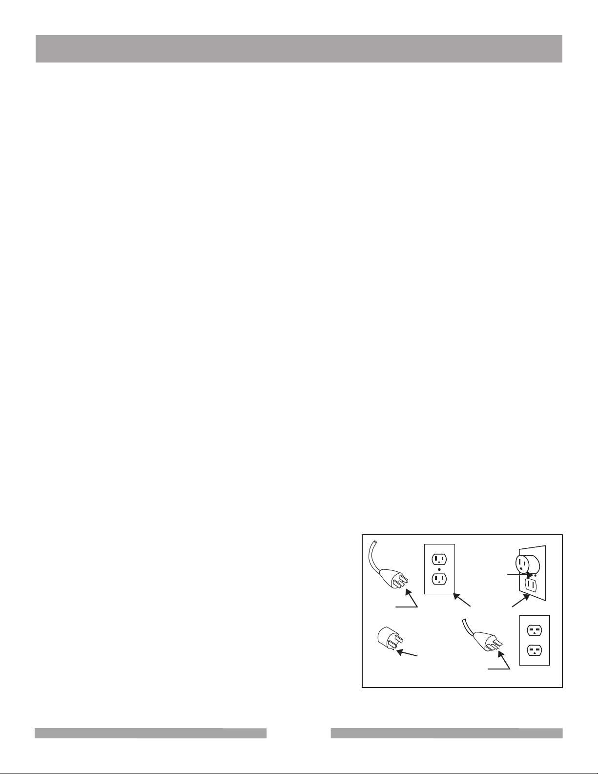
This tool is intended for use on a circuit that has an outlet that looks like the one shown in Sketch A.
The tool has a grounding plug that looks like the plug illustrated in Sketch A. A temporary adapter,
which looks like the adapter illustrated in sketches B and C, may be used to connect this plug to a
2-pole receptacle as shown in Sketch B, if a properly grounded outlet is not available. The temporary
adapter should be used only until a properly grounded outlet can be installed by a qualied electrician. The green-colored rigid ear, plug, and the like, extending from the adapter, must be connected
to a permanent ground, such as a properly grounded outlet box.
NOTE: Use of a temporary adapter is not permitted in Canada.
To reduce the risk of electrocution, keep all connections dry and off the ground.
A Ground Fault Circuit Interrupter (GFCI) should be provided
on the circuit(s) or outlet(s) to be used for this power tool.
Receptacles are available, having built-in GFCI protection, and
Metal Screw
may be used for this measure of safety.
Cover of
Grounded
Outlet Box
Grounding
Pin
(B)
(D)
When using an extension cord, the GFCI should be installed
closest to the power source, followed by the extension cord,
and lastly, the tool.
Grounding
Pin
(A)
ADAPTER
Grounding
Means
(C)
Circuit and Adapter Information
7
Page 8
GP-6 CABMAKER SAFETY
ELECTRICAL REQUIREMENTS AND GROUNDING INSTRUCTIONS
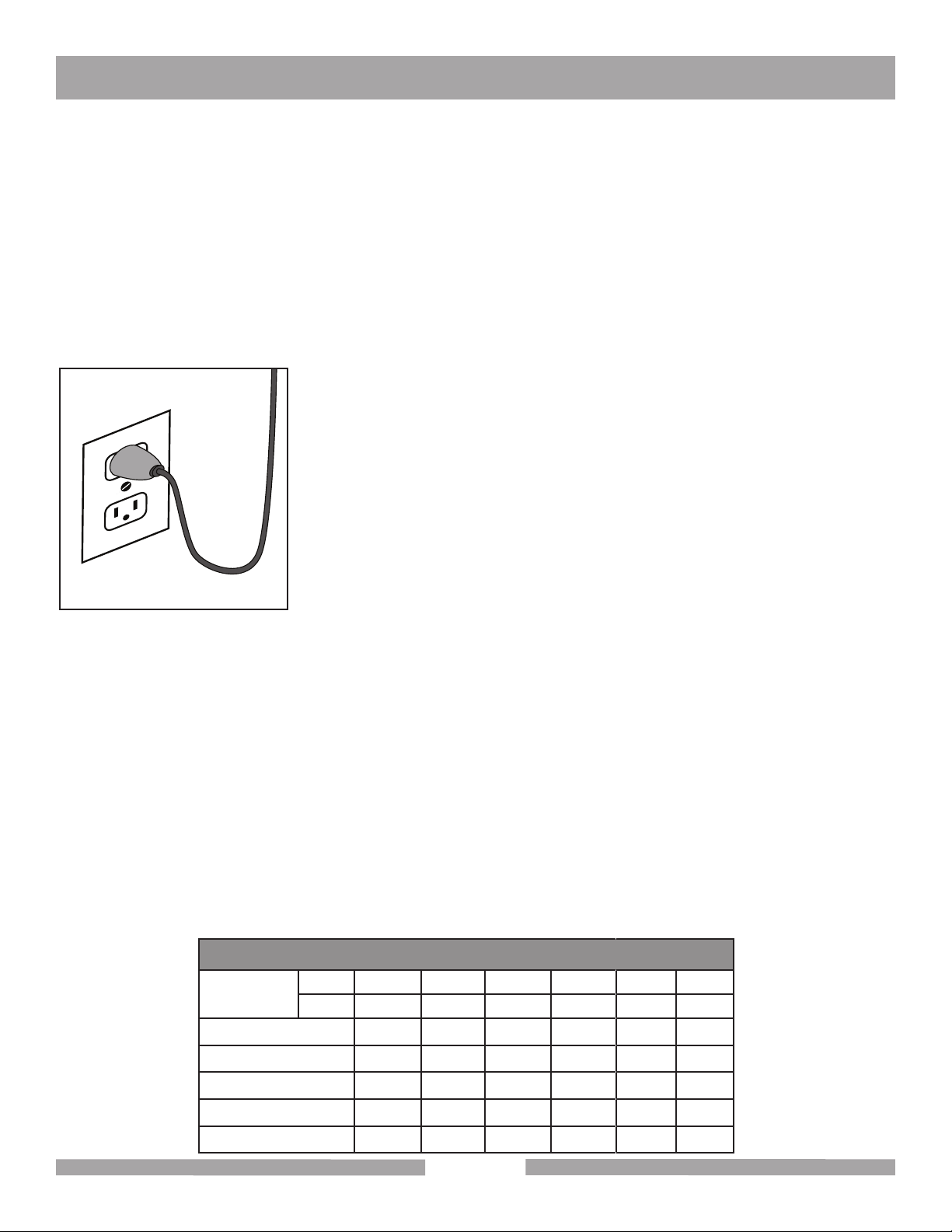
To avoid the possibility of the appliance plug or receptacle getting wet, position the tool to one side of
a wall mounted receptacle. This will prevent water from dripping onto the receptacle or plug. A “drip
loop," shown in illustration below, should be arranged by the user to properly position the power cord
relative to the power source.
The “drip loop" is the part of the cord below the level of the receptacle, or the connector, if an
extension cord is used. This method of positioning the cord prevents the travel of water along the
power cord and coming in contact with the receptacle.
If the plug or receptacle gets wet, DO NOT unplug the cord. Disconnect
the fuse or circuit breaker that supplies power to the tool. Then unplug
and examine for presence of water in the receptacle.
Use only extension cords that are intended for outdoor use. These
extension cords are identified by a marking “Acceptable for use with
outdoor appliances; store indoors while not in use." Use only extension
cords having an electrical rating not less than the rating of the product.
Do not use damaged extension cords. Examine extension cords before
using and replace if damaged. Do not abuse extension cords and do
Drip Loop
not yank on any cord to disconnect. Keep cords away from heat and
sharp edges. Always disconnect the extension cord from the receptacle
before disconnecting the product from the extension cord.
To reduce the risk of electrocution, keep all connections dry and off the ground. Don't touch the plug
with wet hands.
Use of undersized extension cords will result in low voltage to the motor that can result in motor
burnout and premature failure. Barranca Diamond warns that equipment returned to us showing signs
of being run in a low voltage condition, through the use of undersized extension cords, will be repaired
or replaced totally at the customer's expense. There will be no warranty claim.
To choose the proper extension cord:
• Locate the length of extension cord needed in table below.
• Once the proper length is found, move down the column to obtain the correct AWG size required for
that length of extension cord.
EXTENSION CORD LENGTH
Nameplate
Amperes
0 - 5 16 16 16 14 12 12
5.1 - 8 16 16 14 12 10 •
8.1 - 12 14 14 12 10 • •
12.1 - 15 12 12 10 10 • •
115V 25' 50' 75' 100' 150' 200'
250V 50' 100' 150' 200' 300' 400'
15.1 - 20 10 10 10 • • •
8
Page 9

GP-6 CABMAKER SPECIFICATIONS
GP-6 CABMAKER SPECIFICATIONS
Part No: 8300048 (Belts), 8300052 (pads)
Weight: 95 lbs (115 lbs. crated)
Main Motor: Baldor Model 17K017W470
Horsepower: 1/3 HP
Motor Voltage/Frequency: 110 volt/60Hz
Amperage: 5.8 Amps
Motor RPM: 1,725 RPM Fixed
Motor Arbor Diameter: 5/8"
Duty: Continuous, automatic thermal protection shut off, manual restart switch
Motor Arbor Bearings: Ball Bearings, permanently sealed
Motor and Shaft Pulley: 2" OD x 5/8" bore (shaft) and 2" OD x 1/2" bore (motor)
Shaft Bearings: Permanently sealed 5/8" OD shaft ball bearings fit into aluminum tank
and upper hood housing
Wheel Arbor Flanges: 2" OD x 5/8" bore aluminum
Diamond Wheel Mesh Sizes: 80 and 200 mesh (170 mesh may be substituted)
Diamond Resin Belts: 400, 600, 1200, and 3000 mesh 6" x 1-1/2" wide belts
Expandable Rubber Drum: 6" x 1-1/2" wide x 5/8" arbor
Shaft Type: 5/8" precision machined stainless steel
Wheel and Blade Flanges: Aluminum 2" OD x 5/8" bore
Wheel Spacers: 7/8" OD x 5/8" ID aluminum (length varies for wheels and drum)
Convex Polishing End Hub: 6" aluminum hub disc with 5/8"-11" right hand thread
Water Pump: MK Submersible pump (part #155987), variable flow control with 1/4" ID
tubing.
Water Control Valves: 3 stainless steel control valves, brass lever cock valve with barb for 1/4"
ID tubing mounted on rear of the hood.
ON/OFF Switch Box: Lever operated switch box and pigtail female plug receptacle for sub-
mersible pump.
Included Accessories: 5" resin diamond pad set (50, 120, 220, 400, 800, 1,800, 3,500, 8,500 &
13,000 mesh)
5" rigid and 5" rubber backer pads
Three 6" Polytex pads
Three diamond paste syringes
8,000, 14,000, 50,000 mesh diamond paste
6" leather buffing pad
100 mesh green silicon carbide blade sharpening stick
3M On-Off cement
Submersible electric water pump
Water pump tubing
LockLine magnetic manifold and nozzle links/tips
GFCI Switch (110 volt units only)
9
Page 10

GP-6 CABMAKER SETUP
CONTENTS
In the shipping crate, you will find one Barranca Diamond GP-6 Cabmaker mounted to a 3/4" plywood
or plastic baseboard, one package of six rubber feet and mounting screws, one Ground Fault Circuit
Interrupter (GFCI) and one 1" x 1" x 6" sharpening stick.
The accessories for the GP-6 Cabmaker (belts) includes four diamond belts 6" x 1-1/2", Tool Cool bottle, submersible pump and tubing, leather pad, three diamond paste syringes, three Polytex pads, 3M
On/Off cement, sharpening stick and 6" leather pad should be removed from the unit and put aside.
For the GP-6 (pads) the same accessories as the belts unit is accompanied by a Loc-Line magnetic
manifold pump, nozzle links/tips and nine 5" diameter diamond resin pads (50, 120, 220, 400, 800,
1,800, 3,500, 8,500, and 13,000 mesh), 5" rigid and backer pad and 5" rubber backer pad.
UNPACKING
Your GP-6 Cabmaker has been shipped from the factory thoroughly inspected and tested. Remove the
crating material (wood and plastic) from the baseboard and around the machine carefully using a Phillips and standard screwdriver, wire cutter and box cutter knife. Any accessories should be removed
from the unit and put aside.
INSTALLATION OF RUBBER FEET
Enclosed with the unit you’ll find six rubber feet with fastening screws in a plastic bag to be installed
on the underside of the baseboard to level the polisher and reduced vibration during use. Six fastening
positions have been pre-drilled to allow for securely attaching the rubber feet with screws. Mount the
feet by tilting the base board up on one edge and install one of the supplied screws though a rubber
foot and into one of the six predrilled holes. Repeat with the other five sets of screws and rubber feet.
TRANSPORT
For safe transport, disconnect the submersible pump and power cord and remove lubricant and water
from the wheel reservoirs of the GP-6 Cabmaker.
10
Page 11
GP-6 CABMAKER OPERATION AND ADJUSTMENT
PRE-START
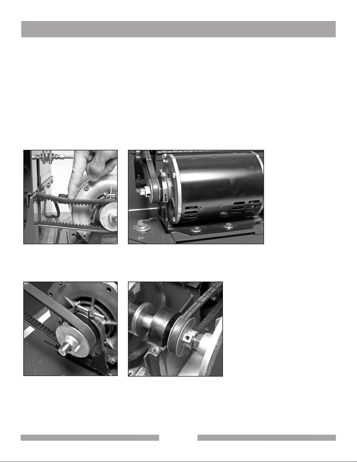
Your unit is assembled at the factory such that the Belt tension between the GP-6 Cabmaker and the
electric motor is set to the required tension. Finger tip pressure on the belt (halfway between the motor
and drive shaft pulleys) should show approximately 1/2" of belt deflection (Fig 1). If the belt requires
adjustment, loosen the motor mounting bolts and move the motor slightly toward the polisher to decrease belt tension or away from the polisher to increase belt tension. Tighten the motor mount bolt
and recheck the belt tension. When the belt is properly tensioned, check that all motor mount bolts are
securely tightened and replace the belt guard.
Check all four motor mount bolts (Fig 2), motor arbor pulley setscrew (Fig 3), wheel shaft pulley setscrew (Fig 4), and belt guard mounting nuts to make sure they are tight.
Fig 1 - Checking belt deflection Fig 2 - Motor mount bolts (one on either side of the
motor and two under the rear of the motor)
Fig 3 - Motor arbor pulley Fig 4 - Wheel shaft pulley
11
Page 12
GP-6 CABMAKER OPERATION AND ADJUSTMENT
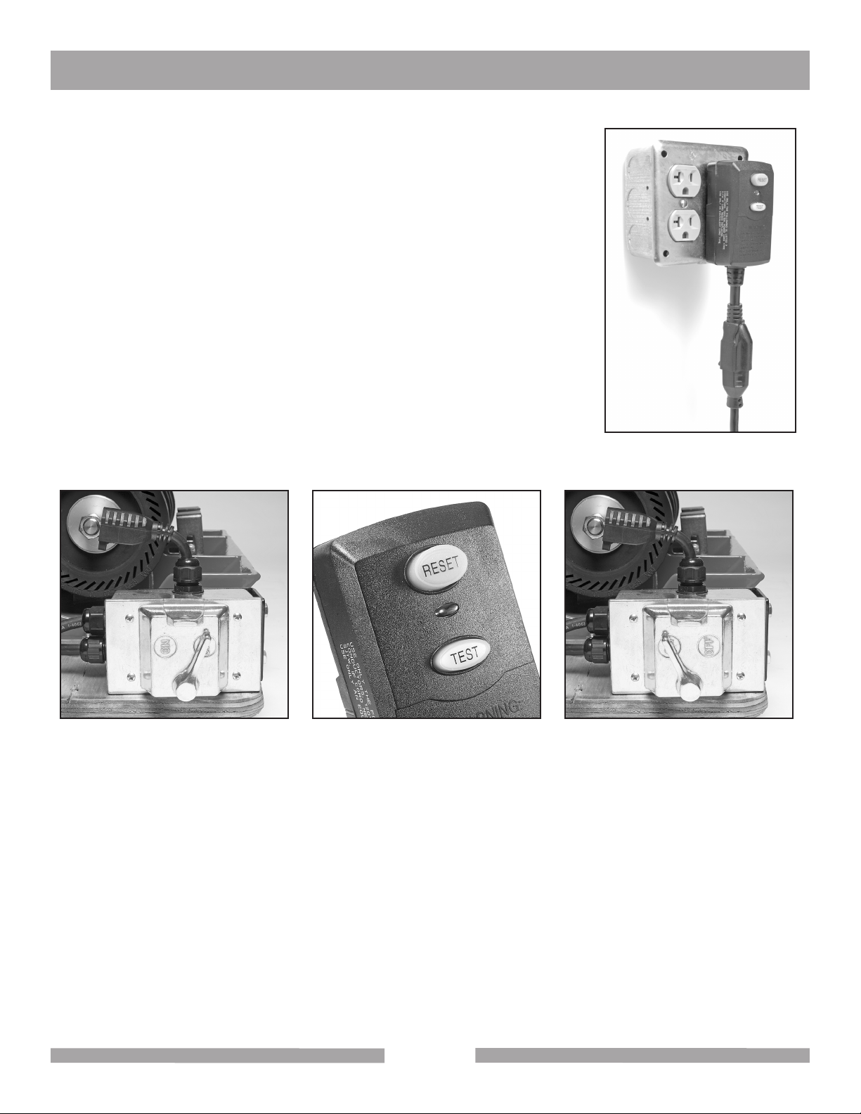
START- UP
Place the GP-6 Cabmaker on a strong flat table or bench. A power test
can now be conducted to make sure the motor is operating and all moving
wheels and blades are correctly aligned and secured to the main shaft.
Plug the enclosed Ground Fault Circuit Interrupter (GFCI) into a 110 to 120
volt 60 Hz minimum 15 amp circuit wall outlet (Fig 5).
If needed, plug an extension cord into the GFCI. If an extension cord is
used, use one that is at least 14-guage wire and no longer than 25 feet.
The GP-6 Cabmaker power cord is attached to the ON/OFF switch box on
the left side of the unit. Make sure the switch box lever is in the OFF (Fig
6) position before plugging into the GFCI or extension cord.
To energize and test the GFCI, push the RESET button (Fig 7) on the
switch and a red window will appear to indicate the switch is energized. If
the TEST button is pushed, the switch will click off indicating the GFCI is
functioning correctly. Push the reset button again to re-energize the GFCI.
Fig 5 - GFCI
Fig 6- Power switch in the OFF
position
Fig 7- GFCI reset button Fig 8- Power switch in the ON
position
The GP-6 Cabmaker is now ready for a power up test to be performed. Turn the lever to the ON position (Fig 8) on the switch box. Make sure no unusual sounds or vibrations occur when the motor engages. If the shaft or motor pulley should loosen, they may hit the sides of the hood, motor, reservoir
base or belt guard causing a rubbing noise. If this happens, shut off the unit, unplug the power cord
from the switch box and adjust, align, and securely retighten the pulleys with an Allen wrench. Liquid
thread locker (removable type) can be used on the setscrew threads to prevent loosening during use.
12
Page 13

GP-6 CABMAKER OPERATION AND ADJUSTMENT
PUMP SET-UP
A submersible electric water pump is used to supply water to the polishing wheels as coolant and
lubricant. The pump has a flow control adjustment on one side and should be adjusted for maximum
water intake (Fig 10). It is recommended that a 5 gallon bucket be used as a water reservoir into which
the submersible pump should be placed. The level of the reservoir water should be monitored so that
water the pump always remains fully submerged.
Fig 9 - Pump inlet adjustment set to
minimum flow
Fig 10 - Pump inlet adjustment set to
maximum flow
Fig 11 - Pump hose attached to water
pump outlet
Connect the pump to the brass ON/OFF barbed lever valve at the rear of the hood with the included
1/4" ID water hose. Insert one end of the 1/4" ID water hose over the water pump outlet (Fig 11) and
the other end over the barbed end of the water valve inlet (Fig 12).
Fig 12 - Water valve in the open
position
Fig 13 - Electrical outlet for water
pump
The pump can be plugged into the female receptacle plug accessory attached to the main switch box
(Fig 13) when using the GP-6 Cabmaker. Power to run the pump will occur once the switch box lever
is placed in the ON position. The pump should be operated in maximum flow setting. This will allow
sufficient water to reach the valve on the rear of the hood to provide water to each of the three needle
valves that control water flow to each of the three work stations.
13
Page 14

GP-6 CABMAKER OPERATION AND ADJUSTMENT
PUMP SET-UP (continued)
Keep the water hose away from the electric motor and belt guard to prevent damage from moving
parts and electric shock hazard. The pump should always be used with clear, clean water so as to
avoid grit/abrasive material, mud or rock fragments from scratching the gemstones during polishing or
clogging the pump valves. For optimal water flow, adjust both the pump and the brass intake valve to
their fully open positions. Should less water be desired, turn the brass lever on the inlet valve to restrict
flow to the hood (Fig 12).
NEEDLE VALVES
The three stainless needle valves (Fig 14) are for fine control of water to each of the three grinding
and polishing stations. For best results, close the valves to the stations not in use. To shut off flow to
a needle valve, simply turn the grey ribbed knob clockwise until it closes to a firm stop (do not overtighten). To open maximum flow to a needle valve, simply turn the grey ribbed knob counterclockwise
until the valve stops. It may take up to 30 seconds for water flow rate to change to a specific station.
Fig 14 - The three stainless needle
valves
Fig 15 - Drain with hose installed
DRAIN VALVES
A length of 3/8" ID tubing is provided with the GP-6 Cabmaker for drainage of excess water from the
front base of the reservoir where a drain is located at the base of the reservoir (Fig 15).
To drain off the excess build-up of cooling water on the diamond wheels and expandable drum belts,
connect length of 3/8" ID clear tubing to the drain and route it into a 5 gallon collection bucket or drain
for dirty water.
Do not recycle dirty water from the drain valves into a collection bucket for pumping back up to the
intake valve on the rear of the hood as the contaminants (rock grit, mud, slurry and abrasive particles)
will likely scratch the gemstone material being worked and possibly clog the stainless steel water control valves or submersible pump.
14
Page 15

GP-6 CABMAKER OPERATION AND ADJUSTMENT
DIAMOND WHEELS
The Diamond GP-6 Cabmaker comes equipped with two 6" OD x 1-1/2" brazed diamond wheels in
two diamond abrasive grit sizes (60/80 and 170/200 mesh or grit). Both wheels are manufactured to
a low tolerance OD circumference run-out for maximum wheel life and to prevent pounding and poor
performance during grinding. The high temperature brazed diamond bond provides excellent abrasive
performance when grinding the rough shape of the gemstone material. Diamond wheels must have an
uninterrupted flow of water during use for proper cooling and flushing of slurry and rock fragments.
A tool rest is attached to the reservoir base of the GP-6 Cabmaker in front of both the 60/80 and
170/200 grit diamond wheels (Fig 16). If a dop-stick is being used to hold the gemstone material, the
user can use the tool rest to securely hold the dop-stick while grinding, shaping and sanding. The tool
rest mount can be adjusted by loosening the positioning bolt (Fig 17), moving the tool rest to the desired height, angle and/or distance from the wheel, and then retightening the positioning bolt. The tool
rest can also be completely removed (Fig 18) from the GP-6 Cabmaker base if the operator so desires.
Fig 16 - Tool rests Fig 17 - Tool rest positioning bolt Fig 18 - Grinding with tool rest
removed
Rough shaping of the gemstone material should be performed first with the 60/80-grit wheel with
maximum water flow from the hood mounted water control valve. It is recommended that you only
pump clean water to the GP-6 Cabmaker water system and never recycle your drain water back to
your grinding wheels or expandable drum.
Due to the steel alloy core construction and brazed nickel diamond bounding of both wheels, a “ringing" noise will be heard during grinding and sanding. This is normal and should be of no concern.
Should coolant/flushing water flow be interrupted while grinding with the brazed diamond wheels, the
diamond may “glaze over" or dull the diamond bond. The diamond bond can be “dressed open" or
sharpened periodically by taking the green carbide stick and lightly touching it to the diamond grinding
face of the wheel while rotating (Fig 19). Only apply a slight pressure - for no more than 2 to 3 seconds
- with full flow of cooling water when “dressing open" the wheels. Do not over-sharpen as the wheel life
will be shortened. Never use the brazed diamond wheels dry under any circumstances.
Always ensure there is a clear, constant drip of water flowing off the rotating wheels into the reservoir
15
Page 16

GP-6 CABMAKER OPERATION AND ADJUSTMENT
tank. Also, don’t over force the gemstone material into the diamond wheel surface while grinding. Allow the diamond bond on the wheel to work smoothly with a constant and steady application of hand
pressure. Rotate your gemstone frequently while grinding to uniformly remove material, nicks and flat
spots while rounding and contouring.
Remember, satisfactory results are dependent on the user's skill and experience, as well as the gemstone and equipment being used.
Fig 19 - Carbide stick applied to diamond wheel
Fig 20 - Resin belt installed and centered on expandable drum
Fig 21 - Polytex pad being applied to
the convex polishing disc
EXPANDABLE DRUM AND DIAMOND RESIN BELTS
The GP-6 Cabmaker comes with four diamond resin belts (6“ OD x 1-1/2" wide) in abrasive grit sizes:
400, 600, 1,200, and 3,000 (6 micron). These are to be placed over the edge and outer rim of the 6" x
1-1/2" rubber expandable drum (Fig 20).
Be sure to center the diamond resin belt so that the width of the belt fits completely over the width of
the rubber drum. Once the GP-6 Cabmaker is turned on, the rotation of the shaft and rubber drum
will cause the drum to expand outward, which will expand the rubber drum and tension the belt on the
drum. It is to be expected that the diamond resin belts will slide somewhat sideways while sanding or
polishing material. To safely and correctly use the belt, shut the unit off and reposition or realign the
belt over the drum and restart the unit.
Under no circumstances should the belts be used dry, as the build-up of heat from the grinding friction
with the gemstone material will cause the belts to wear out prematurely and possibly tear. Therefore,
keep a constant stream of water from the needle water control valve on the top of the hood (far left
valve) on at all times. Do not circulate dirty water from the reservoir tank or from a collection container
back into the water valves or else contaminant abrasive particles may scratch the gemstone. Always
pump from a clear and clean water reservoir to the diamond wheels and belts. For best results always
dry the gemstone material and check for scratches before proceeding to the next wheel or belt diamond grit size. Do not skip belts in the four belt sequence (400, 600, 1,200, and 3,000 grit).
16
Page 17

GP-6 CABMAKER OPERATION AND ADJUSTMENT
POLISHING WITH DIAMOND PASTE
The GP-6 Cabmaker comes with three syringes (5 grams each) of diamond paste in abrasive grit
sizes: 8,000, 14,000 and 50,000 mesh. These diamond pastes are to be used with the three 6" OD
Polytex polishing pads with adhesive backing on the foam covered convex 6" end polishing disc.
Once the gemstone material has been sanded and polished with the 3,000 grit (6 micron) diamond
resin belt, remove the paper backing on the Polytex pad to expose the adhesive surface, placing it
firmly without creases on the foam rubber convex surface of the 6" end polishing disc on the right end
side of the GP-6 Belts model (Fig 21) or left side of the GP6 Pads model.
Lightly smear with your fingertip a small amount of diamond paste on the center of the mounted Polytex pad with the unit operating and the polishing disc rotating. The diamond paste will evenly spread
over the surface of the Polytex pad once polishing of the gemstone starts. Move the gemstone in a
rocking and rotating motion from the center of the disc toward the outside edge to achieve a uniform
polished surface.
Use only one dedicated Polytex polishing pad with each respective diamond paste syringe (i.e. keep
a labeled Polytex pad for the 8,000 grit paste in a zip-lock bag labeled 8,000 grit). Do not use a single
Polytex pad with two or more diamond pastes or else cross-contamination and poor polishing of the
gemstone material may result.
The Polytex pad can be removed from the foam rubber covering of the convex polishing disc by
slowly pulling the Polytex pad off the foam and placing it in a zip-lock plastic bag properly labeled with
the syringe paste diamond grit size for future use. No water or extender fluid is needed to effectively
disperse the diamond paste from the syringe to the Polytex pads. If the adhesive backing becomes
weak with repeated use, you can apply a few drops of 3M On/Off cement to improve the adhesive
connection to the foam disc.
17
Page 18

POLISHING WITH THE LEATHER BUFF PAD
For final polished gemstone results, place the 6" cowhide leather pad (rough side out) on the foam
polishing end disc using the 3M On/Off adhesive cement (red box) to hold the leather pad securely
while buffing the gemstone in a rocking motion (Figs 22 & 23). Only use a small amount (8 to 10
dabs) of 3M On/Off adhesive cement on the smooth cowhide surface, smearing it uniformly before
placing it over the foam rubber on the polishing disc. When the final polish finish of your gemstone
has been achieved, remove the leather disc and place it in a zip-lock bag to protect it for future use.
It is not necessary to use any polishing media or liquid (water) when buffing the gemstone with the
leather disc. Be sure to firmly grip the gemstone by hand or with a dop-stick (wood dowel or aluminum
rod) cemented or epoxied to the back of the gemstone while using the leather buff pad.
Fig 22 Fig 23
18
Page 19

GP-6 CABMAKER OPERATION AND ADJUSTMENT
GP6 CABMAKER (PADS) MODEL
The GP6 Cabmaker (Pads) model is identical to the GP6 Cabmaker (Belts) in that both models use
4" diamond resin belts with an expandable rubber drum to sand and polish gemstone material. The
GP6 Cabmaker (Pads) model however, incorporates an additional feature that includes a 5" rubber
and rigid backer (and resin pad set) that mounts on to the right end of the shaft and uses a Loc-Line
flexible water nozzle and magnetic manifold with submersible pump to direct cooling water to the pads
(Fig 26). This feature of the Pads model enables the user to polish flat gemstone material across the
face of the 5" resin diamond pads by changing pads (grit sizes) with the easy to remove hook and look
material on the vertically mounted backer pad. The expandable drum is mounted on the left side of
the GP6 (Pads) model as opposed to the GP6 (Belts) which is mounted on the right end of the shaft.
SET UP OF LOC LINE SYSTEM ON GP6 CABMAKER (PADS)
Remove the magnetic base manifold from its box and install (thread) the orange mounting connector
to the manifold (Fig 25). The blue loc line links will need to be affixed to the manifold connector and
small orange nozzle tip as well. Follow the instructions on the back of the Loc Line packaging. The
blue flexible line sections will connect to the orange connectors and nozzle tip (Fig 26) by forcing the
links together. If a vise is available use it to hold the orange nozzle while tapping the link segments
together with a mallet. Once assembled, the Loc Line magnetic manifold will need to have the brass
barb male bib threaded into its base (Fig 27) and the 1/2" OD clear tubing attached to the barb. The
3/8" OD clear tubing from the submersible pump inserted into the other end of the 1/2" OD clear tubing.
The magnetic base manifold should be positioned on the metal hood of the GP6 unit adjacent to the
far right end closest to the right end of the shaft. This position will allow for the direction of water flow
to the 5" resin diamond pads during use (Fig 24). A flow restrictor (white clamp) should be installed
on the 3/8" diameter tubing near the junction of the water tube into the 1/2" OD tubing (Fig 28), so that
the user can restrict flow to a slow, steady drip to the center of the 5" resin diamond pads. Should the
customer want more precise flow control of the water to the pads, a brass T-valve can be installed in
the base manifold (not included with the GP6 [Pads]).
Fig 24 Fig 25 Fig 26
19
Page 20

GP-6 CABMAKER MAINTENANCE
Fig 27 Fig 28
USE OF 5" RESIN DIAMOND PADS
Once the 5" resin diamond pad is positioned on the rubber or rigid backer pad on the right end of the
shaft, adjust the Loc Line nozzle tip to the center of the resin diamond pad as close as possible to the
center of the pad. This will allow the water stream/drip to flow over the pad while turning to cool and
flush gemstone grindings during use.
Always pump clean, clear water to the Loc Line manifold and discard dirty water and grindings from
the collection container periodically. Do not recirculate water as contaminants may scratch the gemstone material. The resin diamond pads should never be used dry or they will likely be prematurely
worn out or permanently damaged. A small amount of cooling water flow directed to the center of the
resin diamond pads is required to flush the gemstone grindings and keep the resin cool during use
of the GP6 (Pads) unit. Excess water flow directed to the pads is not necessary and will only make a
mess of your work area. The 5" resin diamond pads can be used with both flat and domed material,
the user should rock and rotate the domed gemstone material during polishing, but for flat polishing
the user needs to move the material flat face across the pad to fully polish the face uniformly. Gemstone material should be held firmly by the user’s finger tips while rotating and or moving the material
over the face of the 5" resin diamond pads. Do not hold the gemstone material too close to the bottom
edge of the resin pad or the material may jam the users finger against the reservoir base. In some
cases, the user may polish gemstones after perform grinding/sanding with the 80 and 170/200 mesh
brazed diamond wheels without need to use the resin diamond belts as the 5" resin diamond pads will
produce final polishing results as good as the resin diamond belts as the pads extend to 13,000 grit
size. Final polishing buffing can be performed with the Polytex pads and leather cowhide mounted to
the polishing foam disc.
20
Page 21

GP-6 CABMAKER MAINTENANCE
DIAMOND WHEEL/CARBIDE WHEEL REPLACEMENT
When worn-out, the diamond wheels and expandable drum can be removed and replaced. For all
models, first prepare the arbor shaft for removal from the body of the GP-6.
1. Remove the belt guard from motor mount (Fig 29).
2. Loosen the motor mount nuts, sliding the motor toward the polisher so that the belt can be
removed from the motor pulley (Fig 30).
3. Unscrew and remove the locking knobs from the hood (Fig 31).
4. Slide the motor away from the GP-6 Cabmaker and rotate the hood back (Fig 32) to expose the
shaft assembly.
Fig 29 - Remove belt guard from motor
mount
Fig 31 - Remove the locking knobs Fig 32 - GP-6 Cabmaker (belts) with hood
Fig 30 - Remove belt from motor pulley
rotated back
21
Page 22

GP-6 CABMAKER MAINTENANCE
GP-6 (BELTS) SHAFT DISASSEMBLY
1. Use a wrench on the jam nut on the right side of the arbor shaft to keep the shaft assembly sta-
tionary and with the other hand remove the polishing hub by rotating it counter-clockwise.
2 Hold the expandable drum in one hand to keep the shaft assembly stationary and with an adjust-
able or box wrench, remove the jam nut on the right end of the unit by turning it counter-clockwise.
3. Lift the shaft assembly out of the bearing seats.
4. Loosen the set screw that secures the right-side bearing collar and slide the bearing off the shaft.
If the set screw has scarred the shaft, it may be necessary to file the burr off the shaft with a small,
fine, flat file or piece of emery paper.
5. Remove the diamond wheels and spacers from the shaft.
GP-6 (PADS) SHAFT DISASSEMBLY
1. Remove the polishing hub on the left side of the arbor shaft by turning it clockwise.
2. Lift the shaft assembly out of the bearing seats.
3 Loosen the set screw that secures the left-side bearing collar and slide the bearing off the shaft. If
the set screw has scarred the shaft, it may be necessary to file the burr off the shaft with a small,
fine, flat file or piece of emery paper.
4. Remove the Diamond wheels and spacers from the shaft.
GP-6 (Carbide) SHAFT DISASSEMBLY
1. With an adjustable or box wrench, remove the jam nut on the left end of the arbor shaft by turning
it clockwise.
3. Lift the shaft assembly out of the bearing seats.
4. Loosen the set screw that secures the left-side bearing collar and slide the bearing off the shaft. If
the set screw has scarred the shaft, it may be necessary to file the burr off the shaft with a small,
fine flat file or piece of emery paper.
5. Remove the carbide wheels and spacers from the shaft.
SHAFT REASSEMBLY
Reassembly of the shaft with the new diamond wheels is the reverse of the disassembly instructions.
Please keep the following points in mind when reassembling:
1. Install diamond wheels with the inside faces facing each other (Figs 33 & 34). Be sure the diamond
wheel bushings are installed.
2. The bearings have a permanently mounted bushing that extends from one side of the center
bearing. This extension must face away from the diamond wheels (Fig 35 & 36) on both ends of the
arbor shaft.
3. The arbor shaft collars have one recessed side and one flat side (Fig 37 & 38). The recessed side
should face the bearing and mate against the extended portion of the bearing bushing.
4. There should be a flange installed on both sides of each diamond wheel and the expandable drum.
Make sure the concave side of the flange (Fig 39) faces the wheels and drum.
5. When installing the shaft assembly back in the GP-6 Cabmaker, make sure the rubber mounted
bearings are centered in the bearing seat (Fig 40 & 41). If the bearings are not centered in the
bearing seats, make sure the aluminum spacers are in the correct order and that the bearings and
arbor collars are properly installed.
22
Page 23

GP-6 CABMAKER MAINTENANCE
6. Install the sanding drum with arrow of rotation facing direction of rotation (Fig 42).
7. Make sure grinding wheel and drum bushings are installed.
8. Install drive belt, retension belt (Fig 43) and replace belt guard.
Fig 33 - Outside face of diamond
wheel
Fig 35 - Bearing correctly installed Fig 36 - Bearing incorrectly installed
Fig 34 - Inside face of diamond
wheel
Fig 37 - Bearing collar correctly
installed
Fig 38 - Bearing collar incorrectly
installed
23
Page 24

GP-6 CABMAKER MAINTENANCE
Fig 39 - Concave side of flange
Fig 40 - Bearing correctly seated Fig 41 - Bearing incorrectly seated
Fig 42 - Arrow on drum indicates
direction of rotation
Fig 43 - Check belt deflection
24
Page 25

GP-6 CABMAKER MAINTENANCE
1-3/8"
Spacer
Bearing
Collar
GP-6 diamond wheel (pads) arbor shaft
1-3/8"
Spacer
1-5/16"
Spacer
1-1/4"
Spacer
3-5/16"
Spacer
3-5/16"
Spacer
Spacer
Shaft
Collar
3/4"
Spacer
3/4"
Bearing
Collar
Bearing
Collar
GP-6 carbide arbor shaft
5/8"
Spacer
GP-6 diamond wheel (belts) arbor shaft
1-1/4"
Spacer
Bearing
Collar
1-5/16"
Spacer
3-5/16"
Spacer
25
Shaft
Collar
1-5/16"
Spacer
Bearing
Collar
Bearing
Collar
Page 26

GP-6 CABMAKER MAINTENANCE
BELT
The GP-6 Cabmaker arbor is driven from the electric motor by a AX-24 rubber belt. The belt tension
is adjusted at the factory. However, if it is necessary to service this belt, unplug the GP-6 Cabmaker
from its power source and remove the fasteners that secure the belt guard housing to the motor. The
belt tension should be checked periodically by removing the guard and depressing the belt in the
middle between both the motor and blade arbor 2" OD pulleys. There should be 1/2" of deflection
when the belt is pushed down (Fig 43). If the belt tension should become loose, poor performance or
slipping will result. If the belt is too tight (i.e. no deflection) the belt, electric motor, pulleys and blade
arbor bearings may wear out prematurely or the motor may overheat and shut off. Belt tension can be
adjusted by loosening the two mounting bolts attached to the base of the motor mount and sliding the
motor cradle base forward or backward to increase or decrease belt tension. Be sure to adequately
retighten the motor mount nuts and replace and attach the belt guard to the table as well.
ARBOR ASSEMBLY
The GP-6 Cabmaker is equipped with a 5/8" OD arbor shaft, two rubber sealed ball bearings and a
2" OD x 5/8" bore die cast zinc coated pulley. Should the bearings wear out on the arbor shaft, grinding and polishing performance and short diamond wheel/belt life may result. Additionally, premature
bearing wear may result in permanent damage to the arbor shaft, bearings, belt and motor. This main
stainless steel shaft arbor assembly can be purchased from Barranca Diamond as a complete unit.
Periodically check the tightness of the hood attachment knobs (Fig 44) to make sure they are securely tightened to the aluminum body of the GP-6 Cabmaker. Should the 2" OD die cast pulleys on either
the motor (Fig 45) or wheel arbor shaft need to be removed or replaced, loosen the setscrew on the
hub of each pulley with a US standard Allen type wrench. The setscrews can be secured with liquid
thread locker (removable type) to prevent loosening due to vibration.
Fig 44 - Hood attachment knobs. Fig 45 - Motor arbor shaft pulley. Fig 46 - Motor reset button.
ELECTRIC MOTOR
The GP-6 Cabmaker is equipped with a Baldor 1/3 HP 1725 RPM single-phase 120 volt 60 Hz 8 amp
motor. The motor shaft has sealed ball bearings and requires no lubrication. The motor is protected
from thermal damage (overheating) with an automatic shut-off switch. If the motor overheats it will
automatically shut off and restart once its internal components cool down and the motor is restarted
26
Page 27

GP-6 CABMAKER MAINTENANCE
manually (red button). Be sure to shut off the main motor by placing the switch lever to the OFF position and disconnecting the power source. After allowing the motor to cool (2 to 3 hours), push the
red reset button on the side of the motor (Fig 46) and restart the unit by turning the switch to ON. If
the motor does not restart after a cool down period, remove the motor and have an authorized repair
service center for Baldor inspect the motor. Barranca Diamond can refer you to an authorized motor
repair service center in your area.
Please note: On GP-6 Cabmakers prior to serial number 0000750 (belts) and 001700 (pads), the
motors do not have a reset switch. Therefore it is imperative that if the motor should stop during operation that the power to the main motor be shut off by placing the toggle switch in the MIDDLE/OFF
position as the motor will restart automatically once cooled down.
SUBMERSIBLE PUMP
Periodically remove the plastic inlet cover on the submersible water pump (Figs 47 & 48). Remove
the filter element (Fig 49) and clean any obstructions such as sludge or rock mud that may be found.
Clean the filter with warm, soapy water. Replace the filter (Figs 50 & 51) and test the pump to ensure
it is functioning properly.
Fig 47 - Water Pump Fig 48 - Slide pump inlet cover off the
pump body
Fig 50 - Replace clean filter Fig 51 - Filter installed
27
Fig 49 - Slide the filter element out the
back of the inlet cover
Page 28

GP-6 CABMAKER PARTS LIST
p
Bill of Materials (GP-6 Cabmaker, Belts Model: part # 8300048)
Accessories
ytitnauQnoitpircseD# traP
1norcim 1 ,dnuopmoC gnihsiloP667161
1norcim 2 ,dnuopmoC gnihsiloP767161
1norcim 4-2 dnuopmoC ,gnihsiloP867161
1tirg 004 ,dnomaiD ,"5.1x"6 ,tleB104093
1tirg 006 ,dnomaiD ,"5.1x"6 ,tleB106093
1tirg 0021 ,dnomaiD ,"5.1x"6 ,tleB002193
1tirg 0003 ,dnomaiD ,"5.1x"6 ,tleB000393
1115V retaW ,pmuPPV-789551
1BRAB "4/1 x TPNF "4/1 ,citsalP ,gnittiF168261
'6DO "8/3 x DI "4/1 ,lyniV ,esoH159231
/1-"4/1 ,wolF ,pmalC493451
162045 1Disc, 6” Sponge Rubber 3/4”
1"2
1rehtaeL "6 ,gnihsiloP ,daP71641
3xetyloP "6 ,gnihsiloP ,daP51641
1elttoB zo 8 ,looC looT927161
1tnemeC FFO-NO csiD M3 ,evisehdA323161
1tirg 001 neerG ,kcitS gnisserD799999
1V511 ,ICFG152610
Assembly, Base
z )HL (tseR looT ,tekcarB244161
166439 Bracket, Tool Rest (RH) zinc plated
162496 Bumper, Recessed 1-1/2"OD x 1/4" ID w/ washer 6
166801
Assembly, Hood
161557 Guard, S
detalp cni
16PG knaT ,riovreseR122261
1debraB "8/1 epiP ssarB ,rotpadA199161
16PG/obmoC baC ,draobesaB168706
3kcen .qS "4/1-1 x 02-"4/1 egairraC ,tloB234161
3"4/1 EAS talF ,rehsaW151915
302-"4/1 xeH ,tuN151893
1
1
4"4/3 x 61-"8/3 xeH ,wercS153527
4"8/3 talF ,rehsaW150923
2)detalp cniz( leetS ,tseR looT479161
2"4/3x 81-"61/5 dH xeH ,wercS151369
2"61/5 EAS talF ,rehsaW151754
281-"81/5 egnalF xeH ,tuN907161
6 "8/7 x 01# lihP dH naP ,wercS878161
1Cover, Baseboard Cab Combo
1tnemdlew ,tnuoM gniraeB,dooH951261
3rebbuR ,hsal
3tnuoM esoH ,tekcarB451261
4"8/3x 23-01 ,dH naP ,wercS578161
4"23-01 xeH ,tuN156269
4"8/3x 02-"4/1 ,dH naP ,wercS778161
4"4/1 talF ,rehsaW151915
2DO "5.2x61-"8/3 ,bonK156161
2"6x61-"8/3 dedaerhT SS ,doR828161
2"61/7 SSU talF ,rehsaW710261
1ssarB retaW ,evlaV299161
28
Page 29

GP-6 CABMAKER PARTS LIST
Bill of Materials (GP-6 Cabmaker, Belts Model: part # 8300048)
p
ytitnauQnoitpircseD# traP
2"61/5 EAS talF ,rehsaW151754
3yerG degdiR ,bonK256161
3F23/01 ,B-VS2VN ,evlaV989161
6rehsaw/w "8/1x23-01 ,braB343161
162505 Tubing, Clear PVC, 1/8 x 1/4
Assembly, Shaft & Wheels
iraeB843161
162507 S
162508 Spacer II, Shaft, Tube 5/8"IDx7/8"OD, Alum.
496200 Wheel, Diamond, Brazed Bond 200 grit, 6"x1/5" 1
162509 Spacer III, Shaft, Tube, 5/8"IDx7/8"OD, Alum.
acer I, Shaft, Tube, 5/8" ID x 7/8" OD, Alum. 1
"5.1x"6 tirg 08 dnoB dezarB ,dnomaiD ,leehW080694
elbadnapxE rebbuR "8/5 x "2/1-1x"6 ,murD600093
2'
1reniater esoh ,munimula ,pilC115261
1L "0.4 x W "01.0 ,nolyN ,eiT605261
1B 81/w ,ssorC235161
1gnol .tf 5.1 ,doR noisicerP SS 303 "8/5 ,tfahS918361
1wercs tes ,DI "8/5 x DO "52.2 ,tleb-V ,yelluP987161
1HL ,81-"61/5 xeH ,tuN407161
6erob "8/5 x DO "2 munimulA ,egnalF038531
2MSCR robrA "8/5 ,gn
1
1
1
1
1 81-"8/5 maJ xeH ,tuN117161
1166065 Polishing Wheel, RH Thread-Comp
1168121 Adapter, Cup Wheel
Assembly, 166065 Switch
.lihP daeH naP "8/5 x 23-6 ,wercS393751
159597 Screw, 10-24 x 5/16" slotted hex washer head grnding 1
1)pmoc( hctiwS A03 ,yrtne edis/poT ,xoB568951
1)pmoc( xoB chtiwS A03 ,rotautcA ,reveL045951
2hctiwS A03 ,gnitnuoM ,etalP984951
1xoB hctiwS A03 ,ffO/nO ,reveL094951
1xoB hctiwS A03 ,nolyN ,gnihsuB997851
1xoB hctiwS A03 ,enahterU ,laeS294951
1xoB hctiwS A03 ,teksaG194951
1TSPD/V021/PH2/A03 ,hctiwS884951
6hcaM spillihP dH tlF "61/5 x 23-6 ,wercS394951
1hcaM spillihP daeH naP "61/5 x 42-01 ,wercS494951
4.hcaM
1talF EAS 01# ,rehsaW963451
1hteeT lanretnI ,kcoL 01# ,rehsaW633851
1rewoP P51-5 x WTJS 3/41 ,droC809951
1pmuP R51-5 x WTJS 3/81 ,droC909951
1Switch, Cab Combo,tekcarB166424
2kceN .qS "4/1-1 x 02-"4/1 egairraC ,tloB234161
2"4/1 EAS talF ,rehsaW151915
202-"4/1 xeH ,tuN151893
2paC lihP daeH naP "2/1 x 02-"4/1 ,wercS254551
1wolleY ,tuN eriW869951
29
Page 30

Bill of Materials (GP-6 Cabmaker, Belts Model: part # 8300048)
GP-6 CABMAKER PARTS LIST
Assembly, Motor & Belt
ytitnauQnoitpircseD# traP
1MPR 5271 ,zH 06 ,V021 ,pH3/1 ,rotoM276161
1wercs tes ,erob 2- 1/2" x 5/8",rotoM ,yelluP161788
4"2/1 x 81-"61/5 DH xeH ,wercS152473
4"61/5 EAS talF ,rehsaW151754
1reppU ,rotoM ,tnuoM8-0166161
1rewoL ,rotoM ,tnuoM966161
2"2/1 x 81-"61/5 DH xeH ,wercS152473
2"61/5 EAS talF ,rehsaW151754
2"61/7 talF ,rehsaW710261
2t, SAE, 1/2alF ,rehsaW150924
2"50.0 x DO "2/1-1 x DI"23/71 talF ,rehsaW015261
281-"61/5 meP ,tuN496161
4kceN .qS "4/1-1 x 02-"4/1 egairraC ,tloB234161
4"4/1 EAS talF ,rehsaW151915
402-"4/1 xeH ,tuN151893
16-PG tleB ,drauG051261
132-XA ,tleB792261
1"74.0-"42.0 x TPN "2/1 pirG ,droC405161
167860
161509
Guard, Inner Belt
Cord, Power 14/3 SJOOW 300V
1
1
30
Page 31

Bill of Materials (GP-6 Cabmaker, Belts Model: part # 8300048)
Accessories
ytitnauQnoitpircseD# traP
1norcim 1 ,dnuopmoC gnihsiloP667161
1norcim 2 ,dnuopmoC gnihsiloP767161
1norcim 4-2 dnuopmoC ,gnihsiloP867161
1tirg 004 ,dnomaiD ,"5.1x"6 ,tleB104093
1tirg 006 ,dnomaiD ,"5.1x"6 ,tleB106093
1tirg 0021 ,dnomaiD ,"5.1x"6 ,tleB002193
1tirg 0003 ,dnomaiD ,"5.1x"6 ,tleB000393
1115V retaW ,pmuPPV-789551
1BRAB "4/1 x TPNF "4/1 ,citsalP ,gnittiF168261
'6DO "8/3 x DI "4/1 ,lyniV ,esoH159231
1"2
/1-"4/1 ,wolF ,pmalC493451
1rehtaeL "6 ,gnihsiloP ,daP71641
3xetyloP "6 ,gnihsiloP ,daP51641
1elttoB zo 8 ,looC looT927161
1tnemeC FFO-NO csiD M3 ,evisehdA323161
1tirg 001 neerG ,kcitS gnisserD799999
1V511 ,ICFG152610
162045 1Disc, 6” Sponge Rubber 3/4”
p
GP-6 CABMAKER PARTS LIST
Bill of Materials (GP-6 Cabmaker, Carbide Wheel Model: part # 8300046)
Accessories
Assembly, Base
166439 Bracket, Tool Rest (RH) zinc plated
162496 Bumper, Recessed 1-1/2"OD x 1/4" ID w/ washer
166801
4/1 ,wolF ,pmalC493451
z )HL (tseR looT ,tekcarB244161
detalp cni
ytitnauQnoitpircseD# traP
1norcim 1 ,dnuopmoC gnihsiloP667161
1norcim 2 ,dnuopmoC gnihsiloP767161
1norcim 4-2 dnuopmoC ,gnihsiloP867161
1tirg 004 ,dnomaiD ,"5.1x"6 ,tleB104093
1tirg 006 ,dnomaiD ,"5.1x"6 ,tleB106093
1tirg 0021 ,dnomaiD ,"5.1x"6 ,tleB002193
1tirg 0003 ,dnomaiD ,"5.1x"6 ,tleB000393
1115V retaW ,pmuPVP-789551
1BRAB "4/1 x TPNM "2/1 ,citsalP ,gnittiF168261
'6DO "8/3 x DI "4/1 ,lyniV ,esoH159231
1"2/1-"
1rehtaeL "6 ,gnihsiloP ,daP71641
3xetyloP "6 ,gnihsiloP ,daP51641
1elttoB zo 8 ,looC looT927161
1tnemeC FFO-NO csiD M3 ,evisehdA323161
1tirg 001 neerG ,kcitS gnisserD799999
1V511 ,ICFG152610
16PG knaT ,riovreseR122261
1debraB "8/1 epiP ssarB ,rotpadA199161
16PG/obmoC baC ,draobesaB168706
3kcen .qS "4/1-1 x 02-"4/1 egairraC ,tloB234161
3"4/1 EAS talF ,rehsaW151915
302-"4/1 xeH ,tuN151893
1
1
4"4/3 x 61-"8/3 xeH ,wercS153527
4"8/3 talF ,rehsaW150923
2)detalp cniz( leetS ,tseR looT479161
2"4/3x 81-"61/5 dH xeH ,wercS151369
2"61/5 EAS talF ,rehsaW151754
281-"81/5 egnalF xeH ,tuN907161
6
6 "8/7 x 01# lihP dH naP ,wercS878161
1Cover, Baseboard Cab Combo
Assembly, Hood
1tnemdlew ,tnuoM gniraeB,dooH951261
161557 Guard, S
3rebbuR ,hsal
3tnuoM esoH ,tekcarB451261
4"8/3x 23-01 ,dH naP ,wercS578161
4"23-01 xeH ,tuN156269
4"8/3x 02-"4/1 ,dH naP ,wercS778161
4"4/1 talF ,rehsaW151915
2DO "5.2x61-"8/3 ,bonK156161
2"6x61-"8/3 dedaerhT SS ,doR828161
2"61/7 SSU talF ,rehsaW710261
1ssarB retaW ,evlaV299161
31
Page 32

p
GP-6 CABMAKER PARTS LIST
Bill of Materials (GP-6 Cabmaker, Carbide Wheel Model: part # 8300046)
ytitnauQnoitpircseD# traP
2"61/5 EAS talF ,rehsaW151754
3yerG degdiR ,bonK256161
3F23/01 ,B-VS2VN ,evlaV989161
6rehsaw/w "8/1x23-01 ,braB343161
162505 Tubing, Clear PVC, 1/8 x 1/4
Assembly, Shaft & Wheels
162507 S
162508 Spacer II, Shaft, Tube 5/8"IDx7/8"OD, Alum.
162509 Spacer III, Shaft, Tube, 5/8"IDx7/8"OD, Alum.
acer I, Shaft, Tube, 5/8" ID x 7/8" OD, Alum.
"1x"6 tirg 001 edibraC nociliS neerG ,leehW0000038
"1x"6 ,tirg 002 edibraC nociliS neerG ,leehW1000038
elbadnapxE rebbuR "8/5 x "2/1-1x"6 ,murD600093
2'
1reniater esoh ,munimula ,pilC115261
1L "0.4 x W "01.0 ,nolyN ,eiT605261
1B 81/w ,ssorC235161
1gnol .tf 5.1 ,doR noisicerP SS 303 "8/5 ,tfahS918361
1wercs tes ,DI "8/5 x DO "52.2 ,tleb-V ,yelluP987161
1HL ,81-"61/5 xeH ,tuN407161
6erob "8/5 x DO "2 munimulA ,egnalF038531
2MSCR robrA "8/5 ,gniraeB843161
1
1
1
1
1
1
1 81-"8/5 maJ xeH ,tuN117161
1 Polishing Wheel w/Setscrew167320
Assembly, 166065 Switch
.lihP daeH naP "8/5 x 23-6 ,wercS393751
159597 Screw, 10-24 x 5/16" slotted hex washer head grnding 1
1)pmoc( hctiwS A03 ,yrtne edis/poT ,xoB568951
1)pmoc( xoB chtiwS A03 ,rotautcA ,reveL045951
2hctiwS A03 ,gnitnuoM ,etalP984951
1xoB hctiwS A03 ,ffO/nO ,reveL094951
1xoB hctiwS A03 ,nolyN ,gnihsuB997851
1xoB hctiwS A03 ,enahterU ,laeS294951
1xoB hctiwS A03 ,teksaG194951
1TSPD/V021/PH2/A03 ,hctiwS884951
6hcaM spillihP dH tlF "61/5 x 23-6 ,wercS394951
1hcaM spillihP daeH naP "61/5 x 42-01 ,wercS494951
4.hcaM
1talF EAS 01# ,rehsaW963451
1hteeT lanretnI ,kcoL 01# ,rehsaW633851
1rewoP P51-5 x WTJS 3/41 ,droC809951
1pmuP R51-5 x WTJS 3/81 ,droC909951
1Switch, Cab Combo,tekcarB166424
2kceN .qS "4/1-1 x 02-"4/1 egairraC ,tloB234161
2"4/1 EAS talF ,rehsaW151915
202-"4/1 xeH ,tuN151893
2paC lihP daeH naP "2/1 x 02-"4/1 ,wercS254551
1wolleY ,tuN eriW869951
32
Page 33

GP-6 CABMAKER PARTS LIST
Bill of Materials (GP-6 Cabmaker, Carbide Wheel Model: part # 8300046)
Assembly, Motor & Belt
ytitnauQnoitpircseD# traP
1MPR 5271 ,zH 06 ,V021 ,pH3/1 ,rotoM276161
1wercs tes ,erob 2- 1/2" x 5/8",rotoM ,yelluP161788
4"2/1 x 81-"61/5 DH xeH ,wercS152473
4"61/5 EAS talF ,rehsaW151754
1reppU ,rotoM ,tnuoM8-0166161
1rewoL ,rotoM ,tnuoM966161
2"2/1 x 81-"61/5 DH xeH ,wercS152473
2"61/5 EAS talF ,rehsaW151754
2"61/7 talF ,rehsaW710261
2t, SAE, 1/2alF ,rehsaW150924
2"50.0 x DO "2/1-1 x DI"23/71 talF ,rehsaW015261
281-"61/5 meP ,tuN496161
4kceN .qS "4/1-1 x 02-"4/1 egairraC ,tloB234161
4"4/1 EAS talF ,rehsaW151915
402-"4/1 xeH ,tuN151893
16-PG tleB ,drauG051261
132-XA ,tleB792261
1"74.0-"42.0 x TPN "2/1 pirG ,droC405161
167860
161509
Guard, Inner Belt
Cord, Power 14/3 SJOOW 300V
1
1
33
Page 34

Bill of Materials (GP-6 Cabmaker, Belts Model: part # 8300048)
Accessories
ytitnauQnoitpircseD# traP
1norcim 1 ,dnuopmoC gnihsiloP667161
1norcim 2 ,dnuopmoC gnihsiloP767161
1norcim 4-2 dnuopmoC ,gnihsiloP867161
1tirg 004 ,dnomaiD ,"5.1x"6 ,tleB104093
1tirg 006 ,dnomaiD ,"5.1x"6 ,tleB106093
1tirg 0021 ,dnomaiD ,"5.1x"6 ,tleB002193
1tirg 0003 ,dnomaiD ,"5.1x"6 ,tleB000393
1115V retaW ,pmuPPV-789551
1BRAB "4/1 x TPNF "4/1 ,citsalP ,gnittiF168261
'6DO "8/3 x DI "4/1 ,lyniV ,esoH159231
1"2
/1-"4/1 ,wolF ,pmalC493451
1rehtaeL "6 ,gnihsiloP ,daP71641
3xetyloP "6 ,gnihsiloP ,daP51641
1elttoB zo 8 ,looC looT927161
1tnemeC FFO-NO csiD M3 ,evisehdA323161
1tirg 001 neerG ,kcitS gnisserD799999
1V511 ,ICFG152610
162045 1Disc, 6” Sponge Rubber 3/4”
GP-6 CABMAKER PARTS LIST
Bill of Materials (GP-6 Cabmaker, Pads Model: part # 8300052)
Accessories
'6DO "8/3 x DI "4/1 ,lyniV ,esoH159231
"4/1 ,wolF ,pmalC493451
66161
162045 Disc, 6" Sponge Rubber 3/4"
Assembly, Base
166439 Bracket, Tool Rest (RH) zinc plated
162496 Bumper, Recessed 1-1/2"OD x 1/4" ID w/ washer
166801
tirg 004( "5 ,daP dnomaiD niseR004573
dlofinam eniL coL tnuoM citengaM5
z )HL (tseR looT ,tekcarB244161
detalp cni
ytitnauQnoitpircseD# traP
1norcim 1 ,dnuopmoC gnihsiloP667161
1norcim 2 ,dnuopmoC gnihsiloP767161
1norcim 4-2 dnuopmoC ,gnihsiloP867161
1tirg 004 ,dnomaiD ,"5.1x"6 ,tleB104093
1tirg 006 ,dnomaiD ,"5.1x"6 ,tleB106093
1tirg 0021 ,dnomaiD ,"5.1x"6 ,tleB002193
1tirg 0003 ,dnomaiD ,"5.1x"6 ,tleB000393
1115V retaW ,pmuPVP-789551
1BRAB "4/1 x TPNM "2/1 ,citsalP ,gnittiF168261
1"2/11rehtaeL "6 ,gnihsiloP ,daP71641
3xetyloP "6 ,gnihsiloP ,daP51641
1elttoB zo 8 ,looC looT927161
1tnemeC FFO-NO csiD M3 ,evisehdA323161
1tirg 001 neerG ,kcitS gnisserD799999
1 Cord, GFCI 120V 15A152610
1)daerht 11-8/5( "5 ,daP rekcaB rebbuR050073
1)daerht 11-8/5( "5 ,daP rekcaB digiR150073
1)tirg 05( "5 ,daP dnomaiD niseR050573
1)tirg 021( "5 ,daP dnomaiD niseR021573
1)tirg 022( "5 ,daP dnomaiD niseR022573
1)
1)tirg 008( "5 ,daP dnmaiD niseR008573
1)tirg 0081( "5 ,daP dnomaiD niseR081573
1)tirg 0053( "5 ,daP dnomaiD niseR053573
1)tirg 0058( "5 ,daP dnomaiD niseR058573
1)tirg 000,31( "5 ,daP dnomaiD niseR031573
1
1
16PG knaT ,riovreseR122261
1debraB "8/1 epiP ssarB ,rotpadA199161
16PG/obmoC baC ,draobesaB168706
3kcen .qS "4/1-1 x 02-"4/1 egairraC ,tloB234161
3"4/1 EAS talF ,rehsaW151915
302-"4/1 xeH ,tuN151893
1
1
4"4/3 x 61-"8/3 xeH ,wercS153527
4"8/3 talF ,rehsaW150923
2)detalp cniz( leetS ,tseR looT479161
2"4/3x 81-"61/5 dH xeH ,wercS151369
2"61/5 EAS talF ,rehsaW151754
281-"81/5 egnalF xeH ,tuN907161
6
6 "8/7 x 01# lihP dH naP ,wercS878161
1Cover, Baseboard Cab Combo
34
Page 35

p
Bill of Materials (GP-6 Cabmaker, Belts Model: part # 8300048)
Accessories
ytitnauQnoitpircseD# traP
1norcim 1 ,dnuopmoC gnihsiloP667161
1norcim 2 ,dnuopmoC gnihsiloP767161
1norcim 4-2 dnuopmoC ,gnihsiloP867161
1tirg 004 ,dnomaiD ,"5.1x"6 ,tleB104093
1tirg 006 ,dnomaiD ,"5.1x"6 ,tleB106093
1tirg 0021 ,dnomaiD ,"5.1x"6 ,tleB002193
1tirg 0003 ,dnomaiD ,"5.1x"6 ,tleB000393
1115V retaW ,pmuPPV-789551
1BRAB "4/1 x TPNF "4/1 ,citsalP ,gnittiF168261
'6DO "8/3 x DI "4/1 ,lyniV ,esoH159231
1"2
/1-"4/1 ,wolF ,pmalC493451
1rehtaeL "6 ,gnihsiloP ,daP71641
3xetyloP "6 ,gnihsiloP ,daP51641
1elttoB zo 8 ,looC looT927161
1tnemeC FFO-NO csiD M3 ,evisehdA323161
1tirg 001 neerG ,kcitS gnisserD799999
1V511 ,ICFG152610
162045 1Disc, 6” Sponge Rubber 3/4”
Assembly, Base
16PG knaT ,riovreseR122261
1debraB "8/1 epiP ssarB ,rotpadA199161
16PG/obmoC baC ,draobesaB168706
3kcen .qS "4/1-1 x 02-"4/1 egairraC ,tloB234161
3"4/1 EAS talF ,rehsaW151915
302-"4/1 xeH ,tuN151893
1
1
detalp cni
z )HL (tseR looT ,tekcarB244161
4"4/3 x 61-"8/3 xeH ,wercS153527
4"8/3 talF ,rehsaW150923
166801
166439 Bracket, Tool Rest (RH) zinc plated
1Cover, Baseboard Cab Combo
2)detalp cniz( leetS ,tseR looT479161
2"4/3x 81-"61/5 dH xeH ,wercS151369
2"61/5 EAS talF ,rehsaW151754
281-"81/5 egnalF xeH ,tuN907161
162496 Bumper, Recessed 1-1/2"OD x 1/4" ID w/ washer 6
6 "8/7 x 01# lihP dH naP ,wercS878161
p
GP-6 CABMAKER PARTS LIST
Bill of Materials (GP-6 Cabmaker, Pads Model: part # 8300052)
Assembly, Hood
161557 Guard, S
Assembly, Shaft & Wheels
162507 S
acer I, Shaft, Tube, 5/8" ID x 7/8" OD, Alum.
162508 Spacer II, Shaft, Tube 5/8"IDx7/8"OD, Alum.
496200 Wheel, Diamond, Brazed Bond 200 grit, 6"x1/5" 1
162509 Spacer III, Shaft, Tube, 5/8"IDx7/8"OD, Alum.
elbadnapxE rebbuR "8/5 x "2/1-1x"6 ,murD600093
Assembly, 166065 Switch
159597 Screw, 10-24 x 5/16" slotted hex washer head grnding 1
.lihP daeH naP "8/5 x 23-6 ,wercS393751
"5.1x"6 tirg 08 dnoB dezarB ,dnomaiD ,leehW080694
1tnemdlew ,tnuoM gniraeB,dooH951261
3rebbuR ,hsal
3tnuoM esoH ,tekcarB451261
4"8/3x 23-01 ,dH naP ,wercS578161
4"23-01 xeH ,tuN156269
4"8/3x 02-"4/1 ,dH naP ,wercS778161
4"4/1 talF ,rehsaW151915
2DO "5.2x61-"8/3 ,bonK156161
2"6x61-"8/3 dedaerhT SS ,doR828161
2"61/7 SSU talF ,rehsaW710261
1ssarB retaW ,evlaV299161
1gnol .tf 5.1 ,doR noisicerP SS 303 "8/5 ,tfahS818361
1wercs tes ,DI "8/5 x DO "52.2 ,tleb-V ,yelluP987161
1HL ,81-"61/5 xeH ,tuN407161
6erob "8/5 x DO "2 munimulA ,egnalF038531
2MSCR robrA "8/5 ,gniraeB843161
1
1
1
1
1
1 81-"8/5 maJ xeH ,tuN117161
1 Polishing Wheel LH Thread-Comp167319
1)pmoc( hctiwS A03 ,yrtne edis/poT ,xoB568951
1)pmoc( xoB chtiwS A03 ,rotautcA ,reveL045951
2hctiwS A03 ,gnitnuoM ,etalP984951
1xoB hctiwS A03 ,ffO/nO ,reveL094951
1xoB hctiwS A03 ,nolyN ,gnihsuB997851
1xoB hctiwS A03 ,enahterU ,laeS294951
1xoB hctiwS A03 ,teksaG194951
1TSPD/V021/PH2/A03 ,hctiwS884951
6hcaM spillihP dH tlF "61/5 x 23-6 ,wercS394951
1hcaM spillihP daeH naP "61/5 x 42-01 ,wercS494951
4.hcaM
1talF EAS 01# ,rehsaW963451
1hteeT lanretnI ,kcoL 01# ,rehsaW633851
1rewoP P51-5 x WTJS 3/41 ,droC809951
1pmuP R51-5 x WTJS 3/81 ,droC909951
1Switch, Cab Combo,tekcarB166424
2kceN .qS "4/1-1 x 02-"4/1 egairraC ,tloB234161
2"4/1 EAS talF ,rehsaW151915
202-"4/1 xeH ,tuN151893
2paC lihP daeH naP "2/1 x 02-"4/1 ,wercS254551
1wolleY ,tuN eriW869951
35
Page 36

GP-6 CABMAKER PARTS LIST
Bill of Materials (GP-6 Cabmaker, Pads Model: part # 8300052)
Assembly, Motor & Belt
ytitnauQnoitpircseD# traP
1MPR 5271 ,zH 06 ,V021 ,pH3/1 ,rotoM276161
1wercs tes ,erob 2- 1/2" x 5/8",rotoM ,yelluP161788
4"2/1 x 81-"61/5 DH xeH ,wercS152473
4"61/5 EAS talF ,rehsaW151754
1reppU ,rotoM ,tnuoM8-0166161
1rewoL ,rotoM ,tnuoM966161
2"2/1 x 81-"61/5 DH xeH ,wercS152473
2"61/5 EAS talF ,rehsaW151754
2"61/7 talF ,rehsaW710261
2t, SAE, 1/2alF ,rehsaW150924
2"50.0 x DO "2/1-1 x DI"23/71 talF ,rehsaW015261
281-"61/5 meP ,tuN496161
4kceN .qS "4/1-1 x 02-"4/1 egairraC ,tloB234161
4"4/1 EAS talF ,rehsaW151915
402-"4/1 xeH ,tuN151893
16-PG tleB ,drauG051261
132-XA ,tleB792261
1"74.0-"42.0 x TPN "2/1 pirG ,droC405161
167860
161509
Guard, Inner Belt
Cord, Power 14/3 SJOOW 300V
1
1
36
Page 37

GP-6 CABMAKER WARRANTY
BARRANCA DIAMOND LIMITED WARRANTY
Please complete the warranty registration card and return. Any problems encountered should be directed to
Barranca Diamond Customer Service department at (800) 630-7682 M-F 8am - 5pm PST.
NOTE THIS INFORMATION FOR FUTURE USE:
MODEL NUMBER:
SERIAL NUMBER:
PURCHASE PLACE:
PURCHASE DATE:
Barranca Diamond warrants to the original retail purchaser for a period of 1 year except as noted, from the
date of purchase all products covered by this Warranty to be free of defects in materials and workmanship.
This Warranty shall not apply to any parts that have been subjected to misuse or improper service, that had
been damaged in transit or handling, or that have been altered or repaired by unauthorized representatives.
This Warranty does not cover defects caused by or resulting from misuse, abuse, neglect or damage caused
by accident or the failure to provide reasonable maintenance. This Warranty is void if the product or any of its
individual components is altered or modied by the purchaser or if the product is used in a manner or with a
blade not recommended by the manufacturer.
Any claim arising under this Warranty must be submitted by the original purchaser within the warranty period
specied above, and shall include proof of purchase. During said warranty period Barranca Diamond shall,
at its option, either replace or repair, at no charge to the original purchaser, any parts or components that are
found to be defective by Barranca Diamond. Barranca Diamond shall not be responsible for or obligated to
pay for freight or other transportation related costs or expenses in connection with any defective products or
components that are either returned to Barranca Diamond’s facility or any authorized repair station and/or any
replacement products or components that are shipped from Barranca Diamond pursuant to this Warranty.
Parts and labor needed to maintain products and the replacement of components due to normal wear and tear
are the purchaser’s responsibility and are not covered by this Warranty. All products or components replaced
under warranty become the property of the manufacturer. All replacement parts will be considered to be part
of the original product and any warranty on such parts will expire coincidentally with the original Warranty.
Barranca Diamond will pay for parts and labor in connection with warranty repairs conducted by Barranca Diamond or its authorized repair centers. Replacement part(s) installed by anyone else will be provided without a
charge for such replacement part(s), but this Warranty will not apply to labor charges in connection therewith.
IN NO EVENT SHALL ANY LIABILITY UNDER THIS WARRANTY EXCEED THE REPLACEMENT COST OF
ANY DEFECTIVE PRODUCT OR COMPONENT THEREOF, AND BARRANCA DIAMOND SHALL NOT BE LIABLE FOR ANY INCIDENTAL OR CONSEQUENTIAL DAMAGES OR FOR ANY OTHER DAMAGE OR LOSS
NOT EXPRESSLY ASSUMED AS SET FORTH HEREIN.
The foregoing constitutes an expressed warranty on the terms set forth above and is the only warranty or
warranties applicable to the products it covers. All other warranties, including, without limitation, the implied
warranty of merchantability and/or tness for a particular purpose or use being denied. This limited warranty is
expressly in lieu of all other warranties, whether expressed or implied.
37
Page 38

GP-6 CABMAKER CUSTOMER SERVICE
Specics Applicable to Limited Warranty of Diamond Blades and Core Bits:
Laser Welded Blade and Bit Warranty:
If the laser weld between the segment and the steel core or barrel fails during normal use, the blade
or bit will be replaced free of charge. Blades and bits damaged due to careless or improper use are
not covered under this warranty.
Brazed Blade, Bit, and Cup Wheel Warranty:
If the brazed bond between the segment and the core, barrel, or cup fails within the rst .050 of segment wear, the blade, bit, or cup will be replaced free of charge. Blades, bits, and cup wheels damaged due to careless or improper use are not covered under this warranty.
Continuous Rim Blade Warranty:
If the bond between the rim and the core fails during normal use, the blade will be replaced free of
charge. Blades and bits damaged due to careless or improper use are not covered under this warranty.
Exclusions:
Barranca Diamond does not warrant the following components, which carry their own manufacturer’s
warranty for the indicated periods:
Electric Motors Manufacturer’s Warranty
Baldor: 1 year
Ryobi: 1 Year
Soga: 1 Year
Gas Engines Manufacturer’s Warranty
Honda: 2 years
Engine Power Information
Engine power ratings are calculated by the individual engine manufacturer and the rating method
may vary among engine manufacturers. Barranca Diamond Products makes no claim, representation
or Warranty as to the power rating of the engine on this equipment and disclaims any responsibility
or liability of any kind whatsoever with respect to the accuracy or the engine power rating. Users are
advised to consult the engine manufacturer’s owners manual and website for specic information
regarding the engine power rating.
38
Page 39

GP-6 CABMAKER CUSTOMER SERVICE
REPLACEMENT PARTS
Replacement parts for this tool may be ordered from your Barranca Diamond distributor or directly from
Barranca Diamond. Please have the following information ready before calling:
• Model and serial number of the machine
• Date of purchase
• Description of parts being ordered (see parts list)
RETURN MATERIALS PROCEDURE
To expedite the service relative to the return of a product purchased through Barranca Diamond, please have
the following information available:
• Model and serial number of the machine
• Date of purchase
• Distributor’s name
Then please call Barranca Diamond at (310) 523-5867 or toll free at 800-630-7682 to obtain a Return Goods
Authorization number (RGA) authorizing the return.
Please Note:
• Ensure your item(s) are prepaid to the destination
• Return items must have been purchased within the previous twelve (12) months
• Follow the packaging instructions in the following section
• Be sure to include the RGA number, return address and your phone number on or within the
return shipping box.
PACKAGING INSTRUCTIONS
Ship the equipment using its original shipping crate if possible. Secure inside the shipping crate. Ensure all
parts are secured in the packaging to prevent movement. Do not ship the equipment partially exposed.
39
Page 40

Barranca Diamond Products, Inc.
1315 Storm Parkway
Torrance, CA 90501
Toll-Free: (800) 421-5830
Phone: (310) 539-5221
Fax: (310) 539-5158
www.barrancadiamond.com
 Loading...