

Page 1

F600 Appliance Installation Guide
Revision 1.3, 2010-11-18
Valid for F600 with field replacable module
Barracuda Networks Inc.
3175 S. Winchester Blvd
Campbell, CA 95008
http://www.barracuda.com
Page 2

Copyright Notice
Copyright 2004-2010, Barracuda Networks
www.barracuda.com
v4.x-090623-06-1119
All rights reserved. Use of this product and this manual is subject to license. Information in this document is subject to change without notice.
Trademarks
Barracuda NG Firewall is a trademark of Barracuda Networks. All other brand and product names mentioned in this document are registered trademarks or
trademarks of their respective holders.
Page 3

Page 4

Contents
General Introduction . . . . . . . . . . . . . . . . . . . . . . . . . . . . . . . . . . . . . . . . 7
About this Manual . . . . . . . . . . . . . . . . . . . . . . . . . . . . . . . . . . . . . . . . . . . . . . . . . . . 7
Warranty Note . . . . . . . . . . . . . . . . . . . . . . . . . . . . . . . . . . . . . . . . . . . . . . . . . . . . . . 7
Safety Instructions . . . . . . . . . . . . . . . . . . . . . . . . . . . . . . . . . . . . . . . . . . 8
Electrical Safety . . . . . . . . . . . . . . . . . . . . . . . . . . . . . . . . . . . . . . . . . . . . . . . . . . . . . 8
General Safety . . . . . . . . . . . . . . . . . . . . . . . . . . . . . . . . . . . . . . . . . . . . . . . . . . . . . . 8
ESD Precautions . . . . . . . . . . . . . . . . . . . . . . . . . . . . . . . . . . . . . . . . . . . . . . . . . . . . 9
Introduction and Package Contents . . . . . . . . . . . . . . . . . . . . . . . . . . . 10
Hardware Configuration . . . . . . . . . . . . . . . . . . . . . . . . . . . . . . . . . . . . . . . . . . . . . . 10
Inspecting the Package . . . . . . . . . . . . . . . . . . . . . . . . . . . . . . . . . . . . . . . . . . . . . . 11
Powering Up and Down . . . . . . . . . . . . . . . . . . . . . . . . . . . . . . . . . . . . . 12
Powering Up the Appliance . . . . . . . . . . . . . . . . . . . . . . . . . . . . . . . . . . . . . . . . . . . 12
Powering Down the Appliance . . . . . . . . . . . . . . . . . . . . . . . . . . . . . . . . . . . . . . . . . 12
The Status LED . . . . . . . . . . . . . . . . . . . . . . . . . . . . . . . . . . . . . . . . . . . . . . . . . . . . 13
Installation and Recovery Using ART . . . . . . . . . . . . . . . . . . . . . . . . . . 14
Using the ART Menu via Serial Console or SSH . . . . . . . . . . . . . . . . . . . . . . . . . . . 14
ART and Central Management . . . . . . . . . . . . . . . . . . . . . . . . . . . . . . . . . . . . . . . . 16
Performing a Recovery Process . . . . . . . . . . . . . . . . . . . . . . . . . . . . . . . . . . . . . . . 16
Using a PAR file on an USB Stick . . . . . . . . . . . . . . . . . . . . . . . . . . . . . . . . . . . . . . . . . . 16
Using ART Recovery without USB Stick . . . . . . . . . . . . . . . . . . . . . . . . . . . . . . . . . . . . . 16
Errors During Recovery . . . . . . . . . . . . . . . . . . . . . . . . . . . . . . . . . . . . . . . . . . . . . . . . . . 17
Connecting to the Network and Configuring . . . . . . . . . . . . . . . . . . . . 18
Field Replaceable Option . . . . . . . . . . . . . . . . . . . . . . . . . . . . . . . . . . . . . . . . . . . . . . . . 18
Default Configuration . . . . . . . . . . . . . . . . . . . . . . . . . . . . . . . . . . . . . . . . . . . . . . . . 19
Passwords . . . . . . . . . . . . . . . . . . . . . . . . . . . . . . . . . . . . . . . . . . . . . . . . . . . . . . . . . . . . 19
Network . . . . . . . . . . . . . . . . . . . . . . . . . . . . . . . . . . . . . . . . . . . . . . . . . . . . . . . . . . . . . . 19
Configuring the Appliance . . . . . . . . . . . . . . . . . . . . . . . . . . . . . . . . . . . . . . . . . . . . 19
Serial Connection via Console Port . . . . . . . . . . . . . . . . . . . . . . . . . . . . . . . . . . . . . . . . . 19
Using LCD Display and Keypad . . . . . . . . . . . . . . . . . . . . . . . . . . . . . . 21
Navigating . . . . . . . . . . . . . . . . . . . . . . . . . . . . . . . . . . . . . . . . . . . . . . . . . . . . . . . . 21
4
Page 5

LCD Display Menu . . . . . . . . . . . . . . . . . . . . . . . . . . . . . . . . . . . . . . . . . . . . . . . . . . 21
Rack Mount Installation Guide . . . . . . . . . . . . . . . . . . . . . . . . . . . . . . . 23
5
Page 6

6 Appliance Installation Guide
Page 7

General Introduction
The information in this user guide has been carefully reviewed and is believed to be accurate. It is valid
from Barracuda NG Firewall firmware version
any inaccuracies that may be contained in this document. This manual may be updated from time to
time. The most up-to-date version of this manual can be found at www.barracuda.com.
Barracuda Networks reserves the right to make changes to the product described in this manual at any
time without notice. This product, including software, if any, and documentation may not reproduced
in full or in part without prior written consent from Barracuda Networks.
About this Manual
This manual provides information for installation and use of the appliance. Installation and
maintenance should be carried out by experienced technicians only.
Warranty Note
5.0. Barracuda Networks assumes no responsibility for
Opening your Barracuda Networks appliance or removing its warranty label unless instructed to do so by Barracuda
Networks support will void your warranty and hardware support.
7 General Introduction
Page 8

Safety Instructions
The following information relates to the safety of installation and maintenance personnel.
Read and follow all instructions before attempting to unpack, install or operate this equipment,
especially before connecting the power adapter.
Electrical Safety
Basic electrical safety precautions should be followed to protect yourself from harm and the appliance
from damage:
• Be aware of the power switch locations on the appliance’s chassis as well as
the emergency power-off switch for the housing room, the disconnection
switch or the electrical outlet. Knowing these locations enables you to quickly
remove electrical power from the system in case an electrical accident occurs.
• Do not work alone when working with high voltage components.
• When working around exposed electrical circuits, another person who is
familiar with the power-off controls should be nearby to switch off the power if
necessary.
• Use only one hand when working with powered-on electrical equipment. This
is to avoid making a complete circuit, which will cause electrical shock. Use
extreme caution when using metal tools, which can easily damage any
electrical components or circuit boards they come into contact with.
• Do not use mats designed to decrease electrostatic discharge as protection
from electrical shock. Instead, use rubber mats that have been specifically
designed as electrical insulators.
• The power supply power cord must include a grounding plug and must be
plugged into grounded electrical outlets.
• To prevent fire or shock hazard, do not expose the unit to rain, moisture or
install this product near water.
• Avoid installation of this product during a lightning storm.
• Ensure that the air vents (openings along the sides and at the backside) are
never blocked and that there is sufficient airflow through the vents to prevent
over-heating.
General Safety
• Keep the area around the appliance clean and free of clutter.
• Locate a safe and dry location to place this product. Keep it away from wet
surfaces/surroundings.
• While working on the system, do not wear loose clothing such as neckties and
unbuttoned shirt sleeves, which can come into contact with electrical circuits
or be pulled into a cooling fan.
• Remove any jewelry or metal objects from your body, which are excellent
metal conductors that can create short circuits and harm you if they come into
contact with printed circuit boards or areas where power is present.
8 Appliance Installation Guide
Page 9

ESD Precautions
Electrostatic discharge (ESD) is generated by two objects with different electrical charges
coming into contact with each other. An electrical discharge is created to neutralize this
difference, which can damage electronic components and printed circuit boards.
The following measures are generally sufficient to neutralize this difference before contact
is made to protect your equipment from ESD:
• Use a grounded wrist strap designed to prevent static discharge.
• Keep all components and printed circuit boards (PCBs) in their antistatic bags
until ready for use.
• Touch a grounded metal object before removing the board from the antistatic
bag.
• Do not let components or PCBs come into contact with your clothing, which
may retain a charge even if you are wearing a wrist strap.
• Handle a board by its edges only; do not touch its components, peripheral
memory modules or contacts.
• When handling chips or modules, avoid touching their pins.
• Put the server board and peripherals back into their antistatic bags when not
in use.
• For grounding purposes, make sure your computer chassis provides excellent
conductivity between the power supply, the case, the mounting fasteners and
the server board.
• After accessing the inside of the system, close back the system and secure it
to the rack unit with the retention screws after ensuring that all connections
have been made.
9 Safety Instructions
Page 10

Introduction and Package Contents
Your new Barracuda NG Firewall F600 is an integrated security appliance preinstalled with Barracuda
NG Firewall firmware. This winning combination offers a ready to run security solution that is flexible,
affordable and easy to deploy.
Hardware Configuration
Table 1 Hardware
Component Description
CPU Intel Dual Core
Memory 4 GB
HDD 1 x 500 GB
Flash Disk 128 MB
LCD Module 2x 20 character LCD
Form Factor 1U rack mount
Dimensions (W/D/H) 4.4 x 42.6 x 39.6 cm
Net Weight 8.5 kg
Power Supply Input Voltage 100 - 240 V, AC
Power Supply Frequency 47 Hz - 63 Hz
Power Supply Watts 300 W
Storage Temperature -20 °C - +70 °C
Operation Temperature 0 °C - 40 °C
Relative Humidity 5% - 95%, non-condensing
Certifications CE, FCC, ROHS
The hardware configuration list in Table 1 was valid at the time this manual was published. The listed components are
subject to change at any time, as Barracuda Networks may change hardware components due to technological
progress. Therefore, the list may not reflect the current hardware configuration of the Barracuda Networks NG Firewall
or NG Control Center appliance it was delivered with.
10 Appliance Installation Guide
Page 11

Inspecting the Package
The following items are included in the package:
• One security appliance
• One power cord
• One ethernet crossover cable (red)
• One ethernet standard cable (grey)
• One serial cable (console)
• Printed Quick Start Guide
• One USB flash drive including documentation and administrative tools
• One t-shirt
• One rack mount kit
Please contact Barracuda Networks support if any of these items is missing.
11 Introduction and Package Contents
Page 12

Powering Up and Down
This chapter describes the procedure used to install your appliance and perform the initial
configuration.
Powering Up the Appliance
• Connect and power on the appliance. The power LED indicates green.
• The current status of the boot process will be shown on the appliance’s LCD
display. You may also use the serial console for this purpose.
• After a few seconds, the boot process will be initiated and the status LED
should start to blink
• Wait until the status LED indicates constant
finished.
Powering Down the Appliance
green.
green: The booting procedure is
You must never turn off the appliance by simply switching it off or otherwise removing power from it.
Always initiate a proper system shutdown as described below.
• The system shutdown must be initiated either using the Barracuda NG Admin
tool, a remote logon to the appliance or by using the LCD display and keypad
on the appliance.
• The current status of the shutdown process will be shown on the appliance’s
LCD display. You may also use the serial console for this purpose. Also, the
status LED will blink
• The status LED will turn off at the end of the shutdown procedure.
green.
12 Appliance Installation Guide
Page 13

The Status LED
Your appliance is equipped with a variety of LEDs. One of them is the Status LED. It is either labeled
with a
between
The table below shows the different meanings of the different glowing states.
Table 2 Status LED Conditions
Color Glowing State Meaning Installation Meaning Normal Operation or ART
heart symbol or the term Status. It indicates the appliance’s operational state by changing colors
green, orange and red and by changing between blinking and steady glowing.
Off Off
Green Blinking Normal installation.
Green Steady
Red Blinking Error during installation.
Red Steady - Appliance is halted and may be disconnected.
Orange Blinking --
Orange Steady - Appliance is in ART mode.
Appliance is powered off or installation has not
initialized far enough for LED control when
installation is started.
Installation was completed successfully,
appliance is halted for reboot or installation was
not yet initialized far enough for LED control.
Appliance is powered off.
Appliance is either booting, shutting down or
performing a system update.
Barracuda NG Firewall is up and running.
An error has appeared preventing Barracuda
NG Firewall from entering the up state.
If no orange light available: appliance is in ART
mode.
Not all appliances support orange and/or red LED colors. Depending on the appliance type, the status LED might be
on by default and it might take some time during boot and installation to start either blinking or changing the color.
Furthermore, the status LED might blink at different frequencies.
13 Powering Up and Down
Page 14
Installation and Recovery Using ART
When your Barracuda NG Firewall is booted for the first time after the installation, ART will generate its configuration.
Therefore, ART is not available unless this process, that is typically running for 5 to 10 minutes, has been finished.
Active Recovery Technology (ART) enables you to perform certain basic configuration operations in
order to recover or reconfigure your appliance outside Barracuda OS. ART is based on a very
small-sized Linux system. It can be accessed either via the serial console or via SSH. On appliances
featuring LCD display and keypad, ART can be invoked from the display as well.
Using the ART Menu via Serial Console or SSH
You get access to the ART menu either by activating Start ART on reboot via the appliance’s LCD
display or by rebooting the appliance while being connected to it via serial console or SSH and
pressing any key during the boot process while Press any key to enter ART is displayed.
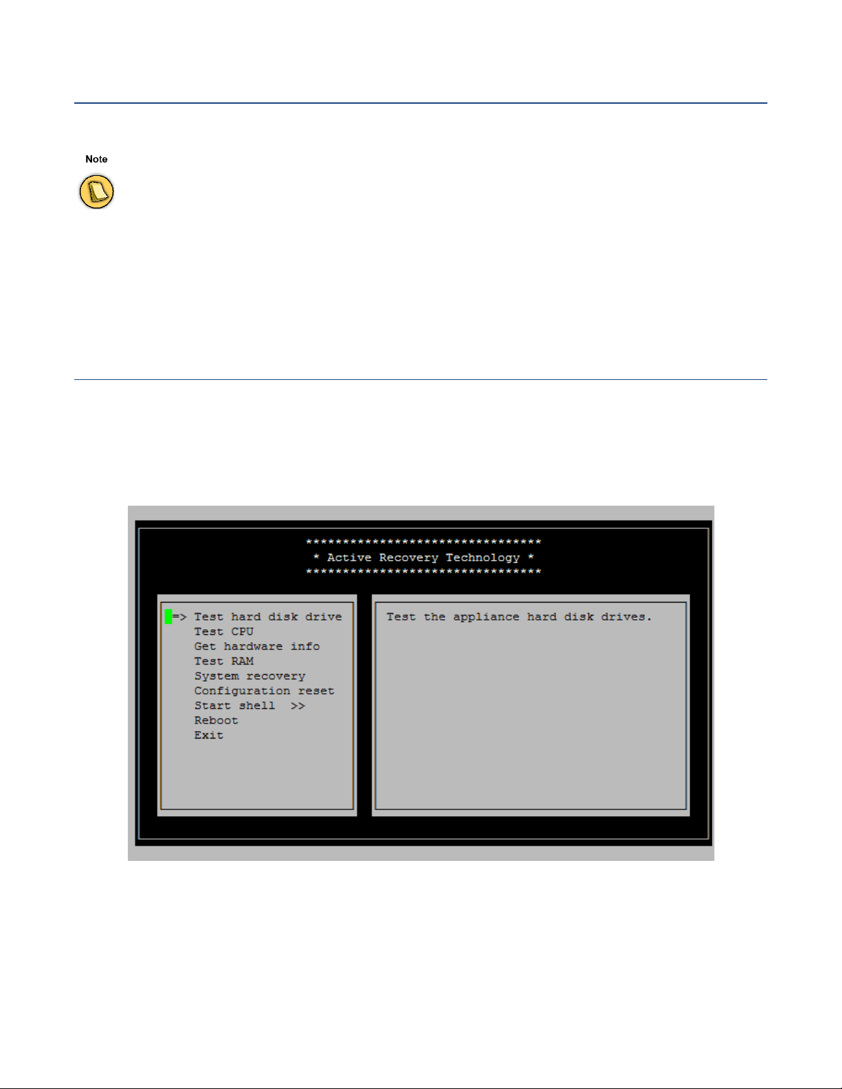
Once the appliance has booted into ART, you will see this menu:
Use the
14 Appliance Installation Guide
Cursor keys, Enter and Escape to navigate.
• Test hard disk drive
Evokes a hard disk check tool. A hard disk can be selected first, then read-only checks for
bad blocks are performed. In case of a positive, hard disk file system repair actions may be
triggered via the CLI only.
Page 15

• Test CPU
Performs a load test of all available CPUs.
• Get hardware info
Displays all available information stored in a hidden partition on the appliance such as serial
number, initial installation date, etc.
• Test RAM
Evokes a RAM checking utility. Note that not the whole existing RAM can be tested as ART
OS occupies some RAM by itself.
• System recovery
Effectively invokes a reinstall of the appliance.
For hard disk based appliances, an installation “*.iso” image as well as a backup PAR file
are stored within a dedicated partition on the hard drive and will be used. Optionally, an *.iso
image on an USB thumb drive connected to the appliance may be used. If no PAR file is
available, the default installation for the corresponding appliance type is chosen. See also
Performing a Recovery Process, page 16.
For flash-only appliances, this option always requires an USB thumb drive connected to the
system.
The system will be recovered either to the release version of Barracuda NG Firewall it was first installed in, losing the
updates installed since then, or to the state stored in a PAR file residing within the art partition of the system drive.
Once your appliance is readily configured, you may save the configuration for ART recovery through Box > Active
Recovery > Save Current Config. This will generate an ISO file within the art partition that will be used during the
next recovery process.
ART system recovery only works if the appliance was installed with Barracuda NG Firewall 5.0. It is not possible to
use ART system recovery on systems that were updated from 4.0 or 4.2.
See
Using ART Recovery without USB Stick, page 16, in order to learn about the ART recovery process.
• Configuration reset
Allows the definition of a new host name, management IP address, default route and
optionally a network driver. This functionality comes in handy if connectivity to an appliance
was lost due to some misconfiguration or activation of an erroneous PAR file.
• Start shell
Enables access to a bash shell within which you may perform certain commands included
with ART.
• Reboot
Reboots the appliance into Barracuda OS.
• Exit
Exits into Barracuda OS.
Currently the only possible reason the ART recovery OS is invoked automatically for is a hard disk
drive flagged as "dirty". This may indicate a hardware failure or a corrupt file system on the hard disk.
The latter might be remedied by an administrator through the shell via a remote login.
15 Installation and Recovery Using ART
Page 16

ART and Central Management
Appliances that are centrally managed using a Barracuda NG Control Center will obviously no longer
be normally centrally manageable once the recovery system is up and running. However, ART is
aware of the appliance being centrally managed and therefore invokes a connection back to the
Control Center, indicting its presence. An administrator can then login remotely to the appliance using
SSH, invoking the ART menu or a command line in order to debug the problem or perform a recovery
process.
Performing a Recovery Process
See the Barracuda NG Firewall Administrator’s Guide in order to learn about creating Portable Archive (PAR) files.
Using a PAR file on an USB Stick
• Be sure that the appliance is powered off.
• Then, insert the USB stick into one of the USB connectors of the appliance and
switch the appliance on. Depending on the appliance type, it may take a few
minutes until the recovery process will start.
• During the recovery process, the status LED of the appliance will flash with
varying speeds. If your appliance is equipped with an LCD display, then the
process information will be displayed there.
• At the end of the recovery process, the status LED’s flashing will be replaced
by steady
• Now, power off the appliance and remove the USB stick.
• Switch the appliance on again. If the appliance was recovered with a standard
Barracuda manufactured USB stick (autodetection), the appliance will perform
another reboot after adjusting some settings.
If the appliance was recovered using an USB stick generated with the
Barracuda NG Install application specifically for this appliance type, the
second reboot is not necessary and the appliance will boot directly into
operation mode.
green glowing and the appliance will beep once.
Using ART Recovery without USB Stick
• If you want to recover using your current configuration, first save your
configuration for ART through Barracuda NG Admin using
> Save Current Config
root directory.
• Boot into the ART menu as described above in (the Status LED blinks
when ART is running) and choose Start recovery. Then, follow the on-screen
instructions.
16 Appliance Installation Guide
Box > Active Recovery
or put a PAR file named box.par into the art partition’s
orange
Page 17

• Recovery is finished as soon as the Status LED steadily indicates green.
Errors During Recovery
If difficulties are encountered during the recovery process, the Status LED will blink red.
Furthermore, error messages will be displayed on the appliance’s LCD display. You may also trace the
output using the serial console.
17 Installation and Recovery Using ART
Page 18

Connecting to the Network and Configuring
Fig. 1 F600 appliance.
The F600 has one 10/100 Mbit (PORT1) as well as ten 10/100/1000 Mbit ethernet ports on its front
side. The non removeable ports are labled from
unlabeled.The management port is
PORT1.
The table below shows the assignment of these connectors to the internal notation.
Table 3 Legend
Label OS Notation
PORT1 port1
PORT1 to PORT7. Ports of replaceable modules are
PORT2 port2
PORT3 port3
PORT4 port4
PORT5 port5
PORT6 port6
PORT7 port7
not labeled port8
not labeled port9
not labeled port10
not labeled port11
Field Replaceable Option
The Barracuda F600 appliance is also available with a 4 x 1Gbit ethernet SFP module to replace the
default 4 x 1 Gbit ethernet RJ45 port bracket.
When replacing the default port bracket with a 4 x 1Gbit ethernet SFP module, be shure to correctly modify the network
settings in Barracuda NG Admin. Please navigate to Config > Box Properties > Identification Settings and Config
> Network > Interfaces > Network Interface Configuration.
18 Appliance Installation Guide
Page 19

Default Configuration
Passwords
Table 4 Default User and Password
Account Type User Name Password
Administrator root ngf1r3wall
You need a valid Barracuda Networks license in order to change the administrator password. In the
demo mode, restrictions in the firmware prevent the appliance from being used in productive
environments.
Network
The ethernet connector PORT1 is preconfigured with the IP address 192.168.200.200 and the
netmask 255.255.255.0.
In standard configuration and upon delivery, no other ethernet connector is configured.
Configuring the Appliance
In order to configure the appliance please copy the Barracuda NG Admin application from the USB
flash drive to your management PC first.
To modify the network settings in Barracuda NG Admin, navigate to
Identification Settings
and Config > Network > Interfaces > Network Interface Configuration.
Serial Connection via Console Port
In order to establish a console connection to the appliance using a serial cable, you need to configure
the serial port on the terminal using the following parameters:
Table 5 Default User and Password
Parameter Value
Baud 19200
Config > Box Properties >
Bits 8
Stop bit 1
Parity None
Handshake None
19 Connecting to the Network and Configuring
Page 20

20 Appliance Installation Guide
Page 21

Using LCD Display and Keypad
Navigating
This security appliance features a key pad with four keys and an LCD panel on the left side of the front
panel. These may be used to obtain certain information and to perform certain commands directly on
the appliance.
left arrow key navigates back or acts like an
The
Escape key while working in the LCD menu.
The
up arrow key navigates up or increases a
value.
The
down arrow key navigates down or decreases
a value.
The
right arrow key navigates forth or acts like an
Enter key for confirming a configuration step.
LCD Display Menu
You may use the LCD display and the keypad to access certain appliance features. Use the up and
down keys to navigate through the items of the main menu.
The LCD menu features the following items from top to bottom:
• Appliance type, OS version and release number
This is the default display.
• IP address and subnet mask
Shows the configured IP address and subnet mask of the appliance.
• Time and date
Shows time and date currently configured on the appliance.
• Uptime of Barracuda OS
The uptime in days, hours and minutes.
• Serial number of the appliance
Unique identifier for the appliance.
• Shutdown menu
Enables you to shut down the appliance.
• Reboot menu
Enables you to reboot the appliance.
• Menu to change the management IP address
Configure the IP address for the management port.
21 Using LCD Display and Keypad
Page 22

• Menu to boot into ART during the next reboot
Enables you to set a flag that will cause the appliance to boot into ART the next time it is
rebooted.
Once set, this flag can not be deleted through the menu. When rebooted, the appliance will
not start Barracuda OS, but ART instead. You may connect to the appliance by using the
serial console or by SSH. A Control Center managed box running in ART mode cannot be
managed through the CC, although it will build a connection to the CC signalling its
presence.
IInstallation and Recovery Using ART, page 14 in order to get in-depth information about Active
See
Recovery Technology.
22 Appliance Installation Guide
Page 23

Rack Mount Installation Guide
Verify that the kit is complete, as shown here. It should contain all the parts as listed below
Fig. 2 Part List: L-Brackets
4 L-brackets.
Fig. 3 Part List: Extension Slide Rails
2 extension slide rails.
Fig. 4 Part List: One Nut Type and Three Screw Types
8 nuts, 6 type B screws, 8 type C screws and type A screws contained in a separate ziplock bag.
23 Rack Mount Installation Guide
Page 24

1.) Start out by disassembling the rail construction.
This must be done prior to mounting.
Fig. 5 Rail Construction Disassembly
Fig. 6 Rail Construction Disassembly
2.) Then, assemble the two inner slides.
For this, use the type B screws on each side of your appliance.
Fig. 7 Inner-Slide Assembly
Fig. 8 Inner-Slide Assembly
Fig. 9 Inner-Slide Assembly
24 Appliance Installation Guide
Page 25

3.) Subsequently, prepare the connection of the inner rail and the L-brackets.
It is important that you make sure to be able to screw on the L-brackets by keeping their screw holes
reachable.
Fig. 10 The Screw Holes
4.) Screw on the L-brackets on both sides of the rail construction.
For this, use the type C screws and the nuts.
Fig. 11 Screwing On the L-Brackets
Fig. 12 Screwing On the L-Brackets
Fig. 13 Fixing the Screws Using the Nuts
25 Rack Mount Installation Guide
Page 26

5.) Then, mount the rail construction into the rack.
Use the L-brackets to achieve this.
Fig. 14 Mounting the Rail into the Rack
6.) Pull out the middle rail of the rail construction.
The figure below shows you how to do this.
Fig. 15 Pulling Out the Middle Rail
26 Appliance Installation Guide
Page 27

7.) Insert the appliance.
Carefully push it into the middle slide.
Fig. 16 Inserting the Appliance
8.) The installation is finished.
Your rack-mounted appliance is now ready for use.
Fig. 17 Built-In Appliance Ready for Operating
27 Rack Mount Installation Guide
Page 28

Page 29

 Loading...