

Baron Services XDD-1000C Modulator Manual
Technical Manual
C-Band 1 MW Transmitter
Pulse Systems Part Number TR-1038
Magnetron SFD 313A
August 22, 2003
Prepared By:
Pulse Systems Inc.
222 Bolivar Street
Canton, MA 02021
Prepared For
Barron Services
4930 Research Drive
Huntsville, AL 35805

TABLE OF CONTENTS
GENERAL DESCRIPTION..................................................................... 2
Introduction.................................................................................. 2
System Specifications .................................................................... 2
General Technical Discussion .......................................................... 2
Mechanical................................................................................... 4
POWER SUPPLY SECTION .................................................................. 6
Technical Approach ....................................................................... 6
Schematic Diagram ........................................................................ 6
Mechanical Considerations.............................................................. 8
Interface ...................................................................................... 8
MODULATOR SECTION....................................................................... 9
Technical Approach ....................................................................... 9
Schematic diagram ........................................................................ 9
Mechanical Considerations............................................................ 10
Interface .................................................................................... 11
MAGNETRON HEATER POWER SUPPLY .............................................. 12
Technical Discussion ................................................................... 12
OPERATING INSTRUCTIONS.............................................................. 13
Procedure For Setting All System Parameters ................................... 13
MAINTENANCE................................................................................ 15
Introduction................................................................................ 15
The Power Supply Section............................................................. 15
The Modulator Section.................................................................. 15
APPENDIX ...................................................................................... 16
Magnetron Specifications.............................................................. 17
Figures...................................................................................... 35

GENERAL DESCRIPTION
Introduction
The system described in this manual consists of four main parts:
A: The Main High Voltage Power Supply
B. The Modulator System
C. The Corner Cutter
D. Filament Power Supply
In order to achieve the design objectives of this contract, our design approach has to
follow state-of-the-art technology in solid-state design. The evolution of third
generation IGBT technology and the various power supply topologies makes it a
challenge to make the right choice for our present application.
The design objective calls for generating narrow pulses of various pulse-widths
under single pulsing conditions. The cathode pulses will drive a CPI Magnetron
operating in the C-Band frequency with minimum peak output power 1.0 Mw.
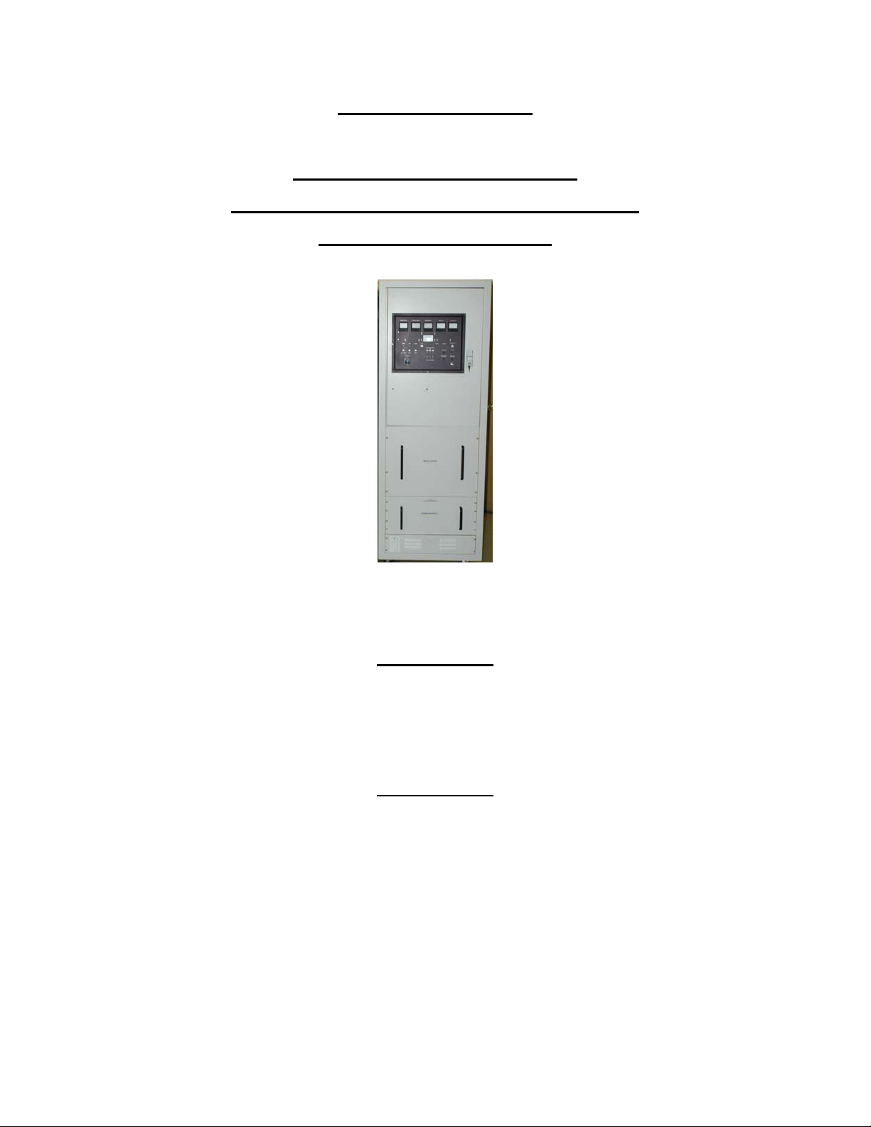
The power supply section is self-contained in an enclosure as shown in Figure 1.0.
Our design is based on series resonance topology driving a full bridge circuit.
The modulator is a hard-tube type, utilizing IGBT technology, and is under oil
environment. The mechanical enclosure for the modulator is shown on Figure 2.0
System Specifications
The specifications for the systems are outlined in the Appendix along with the
magnetron specifications.
General Technical Discussion
As previously mentioned, the whole system consists of the high-voltage power
supply and the solid-state hard tube modulator.
The solid-state power supply contains the following sections:
A. Off-Line Rectifiers, Filters, and Controls
B. Series Resonance Full Bridge Inverter
C. Series Resonance Frequency Modulation Control
D. High Voltage Output Section
E. Low Voltage Power Supplies

F. Hard Tube Modulator Control
G. Solid-State Filament Power Supply
The Modulator section contains the following sections:
A. Switch Driver Assy
B. PRF Driver
C. High Power Switch Section
D. Magnetron Peak Current Detector
The input voltage for the system is 220 VAC single phase and it enters the system
via a connector located in the rear lower panel of the cabinet.
The input line voltage enters the system via a circuit breaker located on the control
panel. The control panel is located on the front upper section of the main cabinet.
Figure 3.0 shows the mechanical configuration of the system. The front view of
cabinet shows the control panel located on the upper section.
The main electrical system diagram is shown on figure 4.0. The main power is
switched on by the circuit breaker on the control panel and is further fused before
entering the power supply section. It enters the front end of the power supply and is
applied to the power factor correction section.
The Power Factor Correction Module performs the rectification, in-rush current
limiting and preregulation of the input line voltage.
The power factor module provides a preregulated DC Voltage level of 360 VDC. The
above 360 VDC is applied to the input of the series resonance converter which, in
turn, provides a final adjustable level of 0-900 VDC available at the modulator
section.
The above DC output is sent to the modulator section through three of wires leaving
the back of the power supply section. The input PRF, which is TTL level, enters the
control panel and is further processed by the Modulator control circuit.
It enters the Modulator Control Circuit, which transforms this input signal to a
selectable pulse-width level proper for triggering the modulator section of the system.
The modulator control circuit performs additional functions, as will be discussed later
under the Power Supply section.
Figure 5.0 shows the complete power supply section of the system. The power
supply also provides the low voltage bias levels required by the modulator. The
modulator section receives the trigger input from the modulator control circuit located

in the power supply.
The function of the modulator is to receive the input signal and provide a high-power
pulse of 36-38 KV at the cathode of the magnetron, thus causing the magnetron to
oscillate at C-Band frequency under the selected pulse width set by the modulator
control circuit.
The maximum cathode peak current under the above conditions is 60 Amperes
peak. The above voltage and current levels result in a peak output power of 1.0
MW. In the meantime, the filament power supply requires programming according to
the magnetron specifications. For the stand-by condition, the filament voltage is set
to 5.0 VDC at 18-22 Amps and is reduced to 2.0 VDC at the maximum duty cycle of
.001.
The cathode voltage is fed to the magnetron via the high voltage bushing located on
top of the modulator.
The magnetron peak current is being monitored via a wide band current transformer
under the magnetron and over the modulator section. The sensitivity of the current
transformer is set to 0.1v/ amp.
For example, if we are looking at the scope displaying the current monitor output, a
6.0 volt peak pulse level will indicate 60 Amps peak magnetron current. Next to the
modulator high voltage output terminal is a spark gap, which prevents the magnetron
from reaching much higher than normal pulse voltage levels. The voltage of the
spark gap is set to 45 KVPK.
When the magnetron misfires the pulse output voltage could theoretically reach a
maximum pulse voltage level of 76 KV. The spark gap limits this level to a maximum
of 45 KV pulse thus reducing the voltage stress level of the system to a more
reasonable level.
Mechanical
As previously mentioned, the mechanical outline drawings of both the power supply
and modulator are shown in Figures 1.0 and 2.0.
Figure 3.0 shows the mechanical outline of the whole system
The power supply is of dry construction and is mounted on rails at the lower section
of the equipment cabinet.
It can be removed by first removing the rear connections at the rear section of the
unit and then slide the whole assembly out of the cabinet.
 Loading...