


Floating Head Greens Mower
Owner's Operating Manual
Serial No. LM101:10001-
"Required reading"
Read this manual and the Owner's Manual for the engine before using the machine.
Ver.1.0

This product can expose you to
chemicals including Carbon
Monoxide, which is known to the
State of California to cause birth
defects or other reproductive harm.
For more information go to
www.P65Warnings.ca.gov.
WARNING:
318yi8-006E
Warning
LM101
Regulations
California Proposition65
(For California, USA)
California Proposition65_001
CALIFORNIA SPARK ARRESTER
(For California, USA)
Operation of this equipment may create
sparks that can start fires around dry
vegetation.
A spark arrester may be required.
The operator should contact local fire
agencies for laws or regulations relating to fire
prevention requirements.
The engine of this machine is equipped with a
spark arrester.
In some areas there are local, state, or federal
regulations requiring that a spark arrester be
used on the engine of this machine.

Thank you for purchasing the Baroness machine.
This manual explains proper handling,
adjustment, and inspection of your machine.
Prior to use, carefully read this manual to
thoroughly understand the contents for safe and
correct operation.
We hope you will use the machine safely, and
take advantage of its best performance.
LM101
Greeting

Caution
696cq5-001
Danger
Danger
Warning
Caution
Important
LM101
Introduction
Read this manual carefully to ensure that you thoroughly understand how to properly operate and maintain this
machine, and to avoid causing injury to yourself or others.
The operator is responsible for operating the machine properly and safely.
Do not perform maintenance on the machine other than that described in this manual.
Be sure to also read the Owner's Manual for the engine, battery, etc.
Maintenance should only be performed by a certified specialist.
If you have any questions concerning maintenance or genuine parts, please contact your local Baroness dealer or
Kyoeisha.
When making inquiries about this machine, please specify the machine's model designation and serial number.
When loaning or transferring this machine, please also provide this manual together with the machine.
Kyoeisha Co., Ltd.
The information described in this manual is subject to change for improvement without prior notice.
When replacing parts, be sure to use genuine Baroness parts or parts designated by Kyoeisha.
Note that the Baroness product warranty may not apply to defects caused by the use of parts from other
companies.
Warning Symbols
This manual uses the following warning symbols for handling precautions that are important for your
safety.
Warning symbol
This symbol indicates the articles regarding “Danger,” “Warning,” or “Caution.”
Those articles describe important safety precautions and so read them carefully to understand completely before
operating the machine.
Failure to adequately follow these safety precautions may cause an accident.
This symbol indicates that serious injury or death will occur if the warning is ignored.
This symbol indicates that serious injury or death may occur if the warning is ignored.
This symbol indicates that injury or damage to property may occur if the warning is ignored.
This symbol indicates precautions on the mechanism of the machine.

Purpose
This machine is intended for cutting turf grass at
golf courses.
Do not use this machine in any way other than
its intended purpose, and do not modify the
machine.
Operating this machine for other purposes and
modifying it may be very dangerous and may
cause damage to the machine.
LM101
Introduction

LM101
Introduction

Safety .............................................................. Page 1-1
Safe Operating Practices ...............................Page 1-2
Disposal .......................................................... Page 2-1
Recycle and Waste Disposal ......................... Page 2-2
Product Overview .......................................... Page 3-1
Specifications .................................................Page 3-2
Names of Each Section ................................. Page 3-3
Safety Signs and Instruction Signs ................ Page 3-4
Handling Instructions .................................... Page 4-1
Preparation for Use ........................................Page 4-2
Inspection Before Use ................................... Page 4-3
Tightening torques ......................................... Page 4-8
Adjustment Before Operating ...................... Page 4-12
Procedure to Start / Stop Engine ................. Page 4-18
Operation of Each Section ...........................Page 4-20
Instruments .................................................. Page 4-26
Travel of Machine ........................................ Page 4-26
Cutting Work ................................................ Page 4-27
Transporting .................................................Page 4-29
LM101
Contents
Maintenance ................................................... Page 5-1
Maintenance Precautions .............................. Page 5-2
Maintenance Schedule .................................. Page 5-4
Greasing ........................................................ Page 5-7
Maintenance (Mower) .................................. Page 5-10
Maintenance (Main Body) ............................Page 5-23
Long-Term Storage ......................................Page 5-25
Troubleshooting Procedures of Aftercut
Appearance ................................................. Page 5-26

LM101
Contents

Safe Operating Practices ...................... Page 1-2
Training ..................................................Page 1-2
Preparation ............................................ Page 1-2
Operation ...............................................Page 1-3
Maintenance and storage ...................... Page 1-4
LM101
Safety
Safety
Page 1-1

Danger
Danger
Warning
LM101
Safety
Failure to adequately follow these safety
precautions may cause an accident resulting in
injury or death.
This machine is designed to ensure safe
operation and has been tested and inspected
thoroughly before shipment from the factory.
The machine is equipped with safety devices
to prevent accidents.
However, whether the machine demonstrates
its original performance level depends on the
manner in which it is operated and handled,
as well as the manner in which it is managed
on a daily basis.
Inappropriate use or management of the
machine may result in injury or death.
Observe the following safety instructions to
ensure safe operation.
Safe Operating Practices
The following instructions include the ones from
CEN standard EN 836: 1997, ISO standard
5395: 1990, and ANSI B71.4-2004.
Training
Read this manual and other training material
1.
carefully.
Be familiar with the controls, safety signs,
and the proper use of the equipment.
If the operator or mechanic can not read
2.
English it is the owner's responsibility to
explain this manual to them.
All operators and mechanics should seek
3.
and obtain professional and practical
instruction.
The owner is responsible for training the
users.
4.
Never allow people unfamiliar with these
instructions to use or service the machine.
Local regulations may restrict the age of the
operator.
The owner/user can prevent and is
5.
responsible for accidents or injuries
occurring to themselves, other people, or
property.
Keep in mind that the owner, operator, and
6.
mechanic are responsible for accidents or
hazards occurring to other people or their
property.
Preparation
Evaluate the terrain to determine what
1.
accessories and attachments are needed to
properly and safety perform the job.
Only use accessories and attachments
approved by the manufacturer.
While operating, always wear substantial
2.
footwear, long trousers, hard hat, safety
glasses, and ear protection. Long hair, loose
clothing, or jewelry may get tangled in
moving parts.
Do not operate the equipment when barefoot
or wearing open sandals.
3.
Inspect the area where the equipment is to
be used and remove all objects such as
rocks, toys and wire which can be thrown by
the machine.
4.
Exercise care in the handling of fuel.
Warning-Fuel is highly flammable.
Take the following precautions.
Store fuel in containers specifically
[1]
designed for this purpose.
Add fuel before starting the engine.
[2]
Never remove the cap of the fuel tank or
add fuel while the engine is running or
when the engine is hot.
Refuel outdoors only and do not smoke
[3]
while refueling.
If fuel is spilled, do not attempt to start the
[4]
engine but move the machine away from
the area of spillage and avoid creating any
source of ignition until petrol vapours have
dissipated.
Replace all fuel tanks and container caps
[5]
securely.
Check that operator's presence controls,
5.
safety switches and shields are attached and
functioning properly.
Do not operate unless they are functioning
properly.
If the brake operation is faulty or the parking
6.
brake lever has noticeable play, be sure to
adjust or repair them before operating the
machine.
Replace faulty mufflers.
7.
Page 1-2
Safe Operating Practices

Operation
Do not operate the engine in a confined
1.
space where dangerous carbon monoxide
fumes can collect.
Only operate in good light, keeping away
2.
from holes and hidden hazards.
3.
Before attempting to start the engine,
disengage all attachments, shift into neutral,
and engage the parking brake.
4.
Start the engine or switch on the motor
carefully according to instructions and with
feet well away from the blades.
5.
Avoid operating the equipment in wet grass,
where feasible.
6.
Always be sure of your footing on slopes.
7.
Walk, never run.
8.
Remember there is no such thing as a safe
slope.
Travel on grass slopes requires particular
care.
To guard against overturning:
[1]
Do not mow excessively steep slopes.
[2]
Do not stop or start suddenly when going
up or downhill.
[3]
Engage clutch slowly, always keep
machine in gear, especially when traveling
downhill.
[4]
Machine speeds should be kept low on
slopes and during tight turns.
9.
Never operate the machine with damaged
guards, shields, or without safety protective
devices in place.
Be sure all interlocks are attached, adjusted
and functioning properly.
10.
Do not change the engine governor settings
or overspeed the engine.
Operating the engine at excessive speed
may increase the hazard of personal injury.
11.
Pay attention not to touch hot parts.
12.
Do the following before leaving the
operator's position.
[1]
Stop on level ground.
[2]
Disengage the cutting unit and traction
drive;
[3]
Set the parking brake;
[4]
Stop the engine.
13.
Stop the engine in the following conditions.
[1]
Before refueling.
Safety
Before removing the grass catcher/
[2]
catchers.
Before making height adjustment unless
[3]
adjustment can be made from the
operator's position.
[4]
Before cleaning blockages.
[5]
Before checking, cleaning, or working the
machine.
[6]
Whenever you leave the machine.
[7]
After striking a foreign object or if an
abnormal vibration occurs.
Inspect the machine for damage and
make repairs before restarting and
operating the equipment.
14.
Keep hands and feet away from the cutting
units and the rotating parts.
15.
Never pick up or carry a lawnmower while
the engine is running.
16.
Look behind and down before backing up to
be sure of a clear path.
17.
Never operate while people, especially
children, or pets are nearby.
18.
Slow down and use caution when making
turns and crossing roads and sidewalks.
19.
Stop the blades rotating before crossing
surfaces other than grass.
20.
Disengage drive to attachments when
transporting or not in use.
21.
When using any attachments, never direct
discharge of material toward bystanders nor
allow anyone near the machine while in
operation.
22.
Do not operate the machine under the
influence of alcohol or drugs.
23.
Take care when loading or unloading the
machine into a trailer or a truck.
Load or unload the machine in a flat and
safe place.
Before loading or unloading, set the parking
brake on the truck or trailer, stop the engine,
and chock the wheels.
When transporting the machine on a truck or
a trailer, set the parking brake, stop the
engine, and fasten the machine to the truck
with a rope or other suitable restraining
device that has sufficient strength.
When using a running board, select one with
sufficient strength, length, and width and that
will not cause the machine to slip.
24.
Close the fuel valve before transporting the
machine.
LM101
Safety
Safe Operating Practices
Page 1-3

LM101
Safety
Use care when approaching blind corners,
25.
shrubs, trees, or other objects that may
obscure vision.
Do not take your eyes off the road ahead. Do
26.
not operate the machine with no hands.
27.
Reduce the throttle setting during engine
run-out and, if the engine is provided with a
shut-off valve, turn the fuel off at the
conclusion of operation.
Maintenance and storage
Disengage drives on level ground,
1.
disengage the cutting unit, set parking brake,
stop engine and disconnect spark plug wire.
Wait for all movement to stop before
adjusting, cleaning or repairing.
2.
To reduce the fire hazard, keep the engine,
silencer/muffler, compartment fuel storage
area, cutting unit and drives free of grass,
leaves, or excessive grease. Clean up oil or
fuel spillage.
3.
Allow the engine to cool before storing in any
enclosure.
4.
Only cover the machine with a sheet after
hot parts have sufficiently cooled down.
5.
Never store the equipment with fuel in the
tank inside a building where fumes may
reach an open flame or spark.
6.
If the engine is provided with a shut-off
valve, shut off valve while storing or
transporting.
7.
Do not store fuel near flames.
8.
Never allow untrained personnel to service
machine.
9.
Allow the engine/muffler to cool before
checking/maintenance.
Appropriately manage and correctly use the
10.
tools necessary for servicing or adjusting the
machine.
Use jack stands to support components
11.
when required.
Carefully release pressure from components
12.
with stored energy.
Make sure that parts such as wires are not
13.
touching each other and that their covers
have not come off.
Use care when checking the cylinders/reels
14.
and bed knives.
Wear gloves and use caution when
[1]
servicing them.
Be careful during adjustment of the
[2]
machine to prevent entrapment of the
fingers between moving blades and fixed
parts of the machine.
Keep hands and feet away from moving
15.
parts.
If possible, do not make adjustments with the
engine running.
16.
Keep all parts in good working condition and
all hardware tightened.
Replace all worn or damaged decals.
17.
Keep all nuts, bolts and screws tight to be
sure the equipment is in safe working
condition.
18.
Check the grass catcher frequently for wear
or deterioration.
19.
If the fuel tank has to be drained, do this
outdoors.
Page 1-4
Safe Operating Practices

Recycle and Waste Disposal ................ Page 2-2
About Recycle ........................................Page 2-2
About the Waste disposal ......................Page 2-2
LM101
Disposal
Disposal
Page 2-1

LM101
Disposal
Recycle and Waste Disposal
About Recycle
Recycling battery etc. is recommended for
environmental conservation and economical
use of resources.
It may be required by local laws.
About the Waste disposal
Make sure that waste generated when
servicing or repairing the machine is disposed
of in accordance with local regulations.
(e.g. waste oil, antifreeze, rubber products, and
wires etc.)
Page 2-2
Recycle and Waste Disposal

Specifications ........................................ Page 3-2
Specifications .........................................Page 3-2
Sound pressure level .............................Page 3-3
Sound power level ................................. Page 3-3
Vibration level ........................................ Page 3-3
Names of Each Section ......................... Page 3-3
Serial Number Plate ...............................Page 3-3
LM101
Product Overview
Safety Signs and Instruction Signs ..... Page 3-4
About Safety Signs and Instruction
Signs ......................................................Page 3-4
Positions of Safety Decals and
Instruction Decals .................................. Page 3-4
Explanation about Safety Decals
and Instruction Decals ........................... Page 3-5
Product Overview
Page 3-1

LM101
Product Overview
Specifications
Specifications
Model LM101
Total
length
Dimensions
Weight
Minimum turning radius -
Engine
Fuel tank capacity Gasoline 0.53 U.S.gals
Fuel consumption 237.57 g/PS・h (rated output) 323 g/kW・h (rated output)
Engine oil capacity 0.15 U.S.gals
Operating width (Mowing width) 22.92 in 55.7 cm
Operating height (Mowing height)
Blades 9 ・ 11 9 ・ 11
Drive
Speed (HST) -
Speed (Mechanical) 2.92 mph (@3,000 rpm) 4.7 km/h (@3,000 rpm)
Efficiency
Maximum inclination for operation -
Tire size 4.10/3.50-6
Tire pneumatic pressure 17.40 psi
Battery -
Total
width
Total
height
Total weight (empty fuel tank) 251.32 lb 114 kg
Grass catcher
Groomer
Traveling wheel (for one
machine)
Model HONDA GX120
Type Gasoline air-cooled engine (OHV) four-stroke single-cylinder
Total displacement 7.20 cu.in.
Maximum output 2.6 kW (3.5 PS)/3,600 rpm
Traveling Mechanical
Mowing Mechanical
with grass catcher 61.02 in 155 cm
without traveling wheel 37.01 in 94 cm
Steering handle 43.70 in 111 cm
*1
*1
*1
7.28 lb 3.3 kg
7.94 lb 3.6 kg
15.21 lb 6.9 kg
118 cm3 (0.118 L)
Gasoline 2.0 dm3 (2.0 L)
0.56 dm3 (0.56 L)
0.118 - 1.142 in [0.118 - 1.063
*2
in]
0.52 acres/hour
(2.92 mph x mowing width x 0.8)
3.0 - 29.0 mm [3.0 - 27.0 mm]
2,094 m2/h
(4.7 km/h x mowing width x 0.8)
120 kPa (1.2 kgf/㎝2)
*2
The factory default maximum engine rpm is 3,100 rpm.
*1
: Total weight includes *1 parts.
*2
: The indicated lowest mowing height is for general application. It may be adjusted according to
the state of green and the bed knife to be installed.
The value in the brackets [ ] is the mowing height of the machine equipped with a groomer.
Page 3-2
Specifications

Sound pressure level
1
2
3
6
7
9
10
11
18
21
22
22
A
23
20
17
19
12
14
16
15
13
8
4
5
quwxcl-081
4ogipb-001
Sound pressure level
This machine was confirmed to have a
continuous A-weighted sound pressure level
of 87 dB by measuring identical machines in
accordance with the procedure specified in
ISO 5395-1:2013.
Sound power level
Sound power level
This machine was confirmed to have a sound
power level of 98 dB by measuring identical
machines in accordance with the procedure
specified in directive 2000/14/EC.
Vibration level
Hand-arm vibration
This machine was confirmed to transmit a
vibration level of 2.70 m/s2 to hands and arms
by measuring identical machines in
accordance with the procedure specified in
ISO 5349-1:2001,ISO 5349-2:2001.
Names of Each Section
LM101
Product Overview
Handle
1
2 Throttle lever
3 Engine switch
4 Main clutch lever
5 Safety lock switch
6 Brake lever
7 Engine
8 Engine clutch cover
9 Light
10 Reel cutter
11 Bed knife
12 Front roller
13 Rear roller
14 Grass catcher roller
15 Grass catcher
16 Groomer
17 Groomer clutch lever
18 FOC (High/Low Clip) selector lever
19 Unit clutch cover
20 Drum clutch cover
21 Drum
22 Traveling tires
23 Stand
A Serial number plate
Product Overview
Names of Each Section_001
Serial Number Plate
The serial number plate indicates the model
and serial number of the machine.
Serial Number Plate_001
Names of Each Section
Page 3-3

Warning
LM101
Product Overview
Safety Signs and Instruction Signs
About Safety Signs and Instruction Signs
Safety decals and instruction decals are
attached to this machine.
Make sure that they are preserved in their
entirety. If they are damaged, become dirty, or
peel off, replace them with new ones.
Part numbers for decals that need to be
replaced are listed in the parts catalog.
Order them from a Baroness dealer or
Kyoeisha.
Positions of Safety Decals and Instruction Decals
6
3
6
2
1
4
Positions of Safety Decals and Instruction Decals_001
5
6
6iul4h-111
Page 3-4
Safety Signs and Instruction Signs

Explanation about Safety Decals and Instruction Decals
Warning
Danger
Danger
Danger
Danger
㹉㸲㸰㸮㸳㸮㸮㸯㸳㸷㸮
1
2
3
4
qigqnx-118
Danger
Danger
qigqnx-126
Danger
Danger
qigqnx-010
K4205002150
DECAL, CAUTION HANDLING
Use lead-free gasoline.
1.
2.
LM101
Product Overview
Read the Owner's Operating Manual.
3.
1
Flying objects - All persons other than the operator
must keep a safe distance from the machine.
4.
May cut your hand or leg - When the blades are
rotating, keep away from the machine.
K4205001760
DECAL, CAUTION PTO
2
May catch your arm - Keep away from PTO moving
parts during the engine running.
Product Overview
K4205001600
DECAL, CAUTION TO MUTILATION
3
May cut your hand or leg - Stop the cutter rotation
and engine. Otherwise you may get injured.
Safety Signs and Instruction Signs
Page 3-5

qigqnx-015
Warning
qigqnx-120
qigqnx-119
LM101
Product Overview
K4205001330
4
DECAL, CAUTION TO NOISE
K4205001300
DECAL, WARNING ENGINE OIL
5
Check engine oil and gearbox levels before starting.
WARNING
CHECK ENGINE OIL AND
GEARBOX LEVELS
BEFORE STARTING
K4205001300
K4209000370
6
DECAL, GREASING EACH 10-HOURS
Add grease every 10 hours.
Page 3-6
Safety Signs and Instruction Signs

LM101
Handling Instructions
Preparation for Use ............................... Page 4-2
Install the Handle ...................................Page 4-2
Connection of Engine Switch Cord ........Page 4-2
Installing the Stand ................................ Page 4-2
Confirmation of the Operation ............... Page 4-3
Inspection Before Use ...........................Page 4-3
Reel Cutter (Cutting Cylinder) and
Bed Knife (Bottom Blade) ...................... Page 4-3
Air Cleaner .............................................Page 4-3
Drum ......................................................Page 4-4
Tire .........................................................Page 4-5
Brake ..................................................... Page 4-5
Wire ....................................................... Page 4-5
Engine ....................................................Page 4-5
Engine Oil .............................................. Page 4-5
Fuel ........................................................Page 4-6
Oil Leakage ............................................Page 4-7
Main Clutch Lever ................................Page 4-24
Drum Clutch Lever ...............................Page 4-24
Unit Clutch Lever ................................. Page 4-25
FOC (High/Low Clip) Selector Lever ... Page 4-25
Engine Clutch Cover ............................Page 4-25
Groomer Clutch Lever ......................... Page 4-26
Instruments .......................................... Page 4-26
Hour Meter ...........................................Page 4-26
Travel of Machine ................................ Page 4-26
Traveling the Machine ......................... Page 4-26
Cutting Work ........................................ Page 4-27
Cutting Work ........................................Page 4-27
Removing/Installing Traveling Tires .... Page 4-27
Removing/Installing Grass Catcher ..... Page 4-28
Transporting .........................................Page 4-29
Handling Instructions
Tightening torques ................................ Page 4-8
Standard tightening torques .................. Page 4-8
Principal tightening torques ................. Page 4-10
Adjustment Before Operating .............Page 4-12
Adjustment of Handle .......................... Page 4-12
Adjustment of Blade Engagement ....... Page 4-12
Adjustment of Cutting Height ...............Page 4-13
Adjustment of Groomer ........................Page 4-16
Procedure to Start / Stop Engine ....... Page 4-18
Start / Stop of Engine .......................... Page 4-18
Operation of Each Section ..................Page 4-20
Precautions for Operating the
Machine ............................................... Page 4-20
Cautions before Leaving the
Machine ............................................... Page 4-20
Description about Operation Decals ....Page 4-20
Light Switch ......................................... Page 4-23
Engine Switch ......................................Page 4-23
Throttle Lever .......................................Page 4-23
Brake Lever ......................................... Page 4-23
Safety Lock Switch .............................. Page 4-24
Transporting Procedure .......................Page 4-29
Page 4-1

1
2
3
45
6
gifnuq-002
Warning
2
1
eo4kem-002
1
5
6
3
2
4
y7fthb-001
LM101
Handling Instructions
Preparation for Use
Install the Handle
Put the handle pin on the left frame into the
1.
hole at the left-side lower edge of the handle.
While pressing the right-side lower edge of
2.
the handle inward, put the handle pin of the
right frame into the hole.
3.
Secure the lower edges (slotted section of
the handle adjusters) of the right and left
sides of the handle to the rear frame stay
from the back with the bolts, conical spring
washers, and washers.
2.
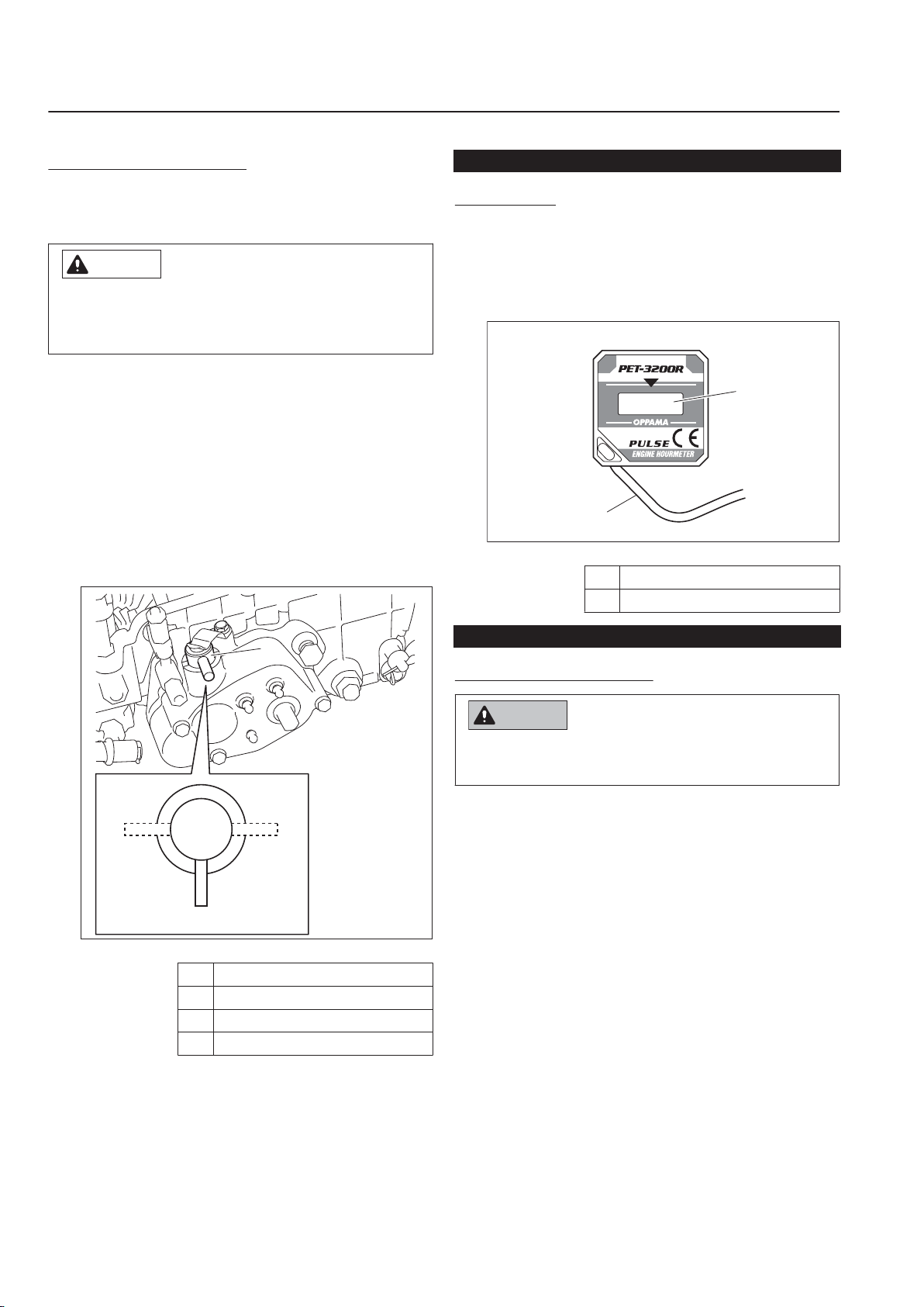
The crimp terminal is secured to the engine
crankcase with a hexagon bolt.
Connection of Engine Switch Cord_001
Plug
1
2 Crimp terminal
Installing the Stand
Install the Handle_001
Lower edge of handle
1
2 Handle pin
3 Handle adjuster
4 Bolt
5 Conical spring washer
6 Washer
Connection of Engine Switch Cord
When the connection of the engine switch
cord is incomplete, the engine will not stop
even if the engine switch is operated.
Check that the cord is correctly connected.
When assembling the handle, check the
connection of the engine switch cord.
There are two connections - plug and crimp
terminal.
The plug is connected to the plug connected
1.
to the engine.
With the inside projection side set to the
1.
right, temporarily secure the left side of the
stand to the frame with the bolt, washer
(inside), and nut (outside).
Put the spring on the projection of the frame
2.
and the projection at the right edge of the
stand.
Installing the Stand_001
Stand
1
2 Bolt
3 Washer
4 Nut
5 Projection
6 Spring
While pulling the right side of the stand
3.
backward, make alignment with the hole in
the frame, and secure the stand with the
bolt, washer (inside), and nut (outside).
Page 4-2
Preparation for Use

Tighten the bolt, washer, and nut at the left
Step:4
Step:3
1
4
2
3
y7fthb-002
1
pd9d4r-015
4.
side of the stand that were temporarily
secured.
Installing the Stand_002
Stand
1
2 Bolt
3 Washer
4 Nut
Handling Instructions
Make sure that the reel cutter (cutting
2.
cylinder) and the bed knife (bottom blade)
are not cracked.
Check to see how much the reel cutter
3.
(cutting cylinder) and the bed knife (bottom
blade) are worn.
4.
Make sure that the reel cutter (cutting
cylinder) and the bed knife (bottom blade)
have not changed color due to heat from
grinding.
5.
Check to see whether or not the second
edge face (relief) remains at the point of
reel cutter (cutting cylinder).
6.
Make sure that the welding between the
reel cutter (cutting cylinder) and the disc
has not come off.
Air Cleaner
Inspection of Air Cleaner
LM101
Handling Instructions
Confirmation of the Operation
Check that the brake operates completely.
1.
Check that the engine clutch operates
2.
completely.
If necessary, make adjustment.
3.
Inspection Before Use
Be sure to perform an inspection before you
start using the machine so that you will be able
to take advantage of its optimum performance
for a long period of time.
Reel Cutter (Cutting Cylinder) and Bed Knife (Bottom Blade)
Inspection of Reel Cutter (Cutting Cylinder) and Bed Knife (Bottom Blade)
The reel cutter (cutting cylinder) and bed knife
(bottom blade) may become dull due to
frequent use, objects crushed during mowing,
or damage caused during transportation.
Inspect the reel cutter (cutting cylinder) and
bed knife (bottom blade), and if necessary,
adjust the blade engagement, perform back
lapping, or resharpen or replace the reel
cutter (cutting cylinder) and the bed knife
(bottom blade).
Check to see whether or not the edge of
1.
the reel cutter (cutting cylinder) and the bed
knife (bottom blade) are too blunt to cut.
For details on handling the engine, please
refer to the Engine's Owner's Manual.
The air cleaner is a component that removes
dirt from the intake air to prevent wear of the
cylinder liners and piston rings so that the
engine will always operate smoothly.
A contaminated air cleaner element may
cause malfunction of the engine.
Make sure that there is no damage to the
1.
air cleaner.
Make sure that the air cleaner element is
2.
not contaminated.
Inspection of Air Cleaner_001
Air cleaner
1
Inspection Before Use
Page 4-3

Caution
Important
1
2
3
6
4
5
7
yt4sup-014
LM101
Handling Instructions
Cleaning of Air Cleaner
For details on handling the engine, please
refer to the Engine's Owner's Manual.
A contaminated air cleaner elements may
cause malfunction of the engine.
To maximize the life of the engine, clean the
air cleaner properly.
Remove the wing screw, and then remove
1.
the cover.
2.
Remove the screw, and then remove the air
cleaner elements.
3.
Remove the urethane element from the
paper element.
When cleaning the paper element, do not use
petroleum solvents.
Replace the air cleaner elements when it gets
damaged or dirty.
Clean the urethane element with white
4.
kerosene and then soak it in the engine oil
and wring out.
Remove dirt and dust from the paper
5.
element with blowing air or patting.
Assemble the paper and urethane
6.
elements.
Attach the air cleaner elements with the
7.
screw.
Set the cover, and then secure it firmly with
8.
the wing screw.
Drum
Inspection of Drum
Make sure that the drum is not cracked or
1.
damaged.
Make sure that there is no abrasion or
2.
adhesion of the drum.
Make sure that there is no play in the fit of
3.
the drum and the bearing.
Cleaning of Air Cleaner_001
Wing screw
1
2 Cover
3 Screw
4 Air cleaner element
5 Urethane element
6 Paper element
7 Gasket
Page 4-4
Inspection Before Use

Danger
Danger
Caution
Important
1
2
bgmiun-019
1
2
3
bgmiun-015
LM101
Handling Instructions
Tire
Inspection of Tires
Check the pneumatic pressure of the tires.
1.
2.
Make sure that there are no cracks,
damage or abnormal wear.
Tire size Pneumatic pressure
Tire for
traveling
4.10/3.50-6
120 kPa (1.2 kgf/
cm2)
Brake
Inspection of Brake
Make sure that the brake wire is not cracked
or damaged.
If the wire is cracked or damaged, replace it
with a new one immediately.
Engine Oil
Inspection of Engine Oil
For details on handling the engine, please
refer to the Engine's Owner's Manual.
Screw the oil level gauge firmly.
Stop the engine, wait for 10 to 20 minutes
1.
for the engine to cool down, and then check
the oil level.
Position the machine so that the engine will
2.
be level, then check the engine oil level
without screwing the oil level gauge into the
oil filling port.
Handling Instructions
Park the machine on a flat place.
Do not park the machine on a slope.
Pull up the brake lever and make sure that
1.
the brake can operate completely.
Pull the brake lever up to the top and make
2.
sure that it can lock the brake lever.
Make sure that the brake is not applied
3.
even slightly after releasing the brake lever.
Wire
Inspection of Wire
Make sure that the wire is not cracked or
1.
damaged.
If the wire is cracked or damaged, replace it
2.
with a new one immediately.
Engine
Inspection of Engine-Associated Parts
For details on handling the engine, please
refer to the Engine's Owner's Manual.
Check the fuel system parts for loosened or
1.
cracked joints and leakage. Replace the
parts if necessary.
Blow compressed air to clean any grass or
2.
flammable materials that may be attached
on or around the muffler.
Inspection Before Use
Inspection of Engine Oil_001
Oil level gauge (Oil filling port)
1
2 Drain plug
The appropriate engine oil level should be
3.
between the upper and lower limit lines on
the gauge.
Inspection of Engine Oil_002
Oil level gauge
1
2 Upper limit
3 Lower limit
Screw the oil level gauge firmly.
4.
Page 4-5

Important
Important
Important
Important
1
2
bgmiun-019
1
2
guc5f6-012
Danger
Danger
Warning
Warning
Caution
LM101
Handling Instructions
Supply of Engine Oil
For details on handling the engine, please
refer to the Engine's Owner's Manual.
Do not supply too much engine oil. Otherwise,
the engine may be damaged.
Do not mix different types of engine oil.
Be sure to use engine oil that is classified as
API Service Grade SE or higher, with an SAE
Viscosity that is appropriate for the operating
environment (ambient temperature).
Screw the oil level gauge firmly.
Fuel
Inspection of Fuel Quantity
Level the machine and then remove the tank
cap to inspect fuel quantity from the fill port.
Inspection of Fuel Quantity_001
Tank cap
1
2 Fuel tank
Fuel Supply
Remove the oil level gauge.
1.
Through the oil filling port, supply new
2.
engine oil until the engine oil reaches a
level in the upper limit lines on the oil level
gauge.
Position the machine so that the engine will
3.
be level, then check the engine oil level
without screwing the oil level gauge into the
oil filling port.
Screw the oil level gauge firmly.
4.
Supply of Engine Oil_001
Oil level gauge (Oil filling port)
1
2 Drain plug
Do not supply fuel above FULL level of the
fuel gauge.
If you supply too much fuel, it might overflow
from the fuel cap when you travel or work on a
slope.
Keep fire away while refueling.
Do not smoke while refueling.
Supply fuel after the engine is stopped and
has well cooled down.
Pay attention not to touch hot parts.
Inspect the fuel quantity and put fuel
(gasoline) if insufficient.
The fuel tank capacity is approximately 2.0
dm3 (2.0 L).
Page 4-6
Inspection Before Use

1
2
A
2e4emp-008
Fuel Supply_001
Fuel strainer
1
2 Filling opening
A Maximum limit of fueling
Oil Leakage
Inspection of Oil Leakage
LM101
Handling Instructions
Handling Instructions
After approximately 50 hours of operation,
some joints may be loosened and oil and
grease may leak.
Be sure to retighten the parts.
Check the bottom of the machine for oil and
grease leakage.
Inspection Before Use
Page 4-7

Important
M
4 T
4.8
tib3yb-001
LM101
Handling Instructions
Tightening torques
Standard tightening torques
Bolts and Nuts
A number of bolts are used in each part of this machine.
Be sure to re-tighten the bolts and nuts, because they may be loosened at the earlier stage of the
use.
As to the bolts and nuts without any special instruction, tighten them in appropriate tightening torque
with proper tool.
Too much tightening may cause the looseness or damage of the screw.
The strength of tightening is determined by types of screws, strength, the friction of thread face or
base face and others.
The table below is for the galvanized or parkerized bolts.
In case that the strength of internal thread is weak, it is not applied.
Do not use rusty or sand attached "screw."
Otherwise, it may cause insufficient tightening even if you apply the specified tightening torque.
The friction of the screw face becomes higher and the tightening torque is canceled out by the
friction, therefore sufficient tightening cannot be applied.
If "screw" is wet by water or oil, do not tighten it with normal tightening torque.
If the screw is wet, the torque coefficient will get smaller and it may result in too much tightening.
Too much tightening may cause looseness by the screw stretched or result in damage.
Do not use a bolt experienced too much burden.
Using the impact wrench requires the skill.
Do exercise as much as possible for steady tightening.
General bolt
Strength classification 4.8
Nominal
diameter
N-m kgf-cm lb-in
M5 3 - 5 30.59 - 50.99 26.55 - 44.26
M6 7 - 9 71.38 - 91.77 61.96 - 79.66
M8 14 - 19 142.76 - 193.74 123.91 - 168.17
M10 29 - 38 295.71 - 387.49 256.68 - 336.34
M12 52 - 67 530.24 - 683.20 460.25 - 593.02
M14 70 - 94 713.79 - 958.52 619.57 - 831.99
M16 88 - 112 897.34 - 1142.06 778.89 - 991.31
M18 116 - 144 1,182.85 - 1,468.37 1,026.72 - 1,274.54
M20 147 - 183 1,498.96 - 1,866.05 1,301.10 - 1,619.73
M22 295 3,008.12 2,611.05
M24 370 3,772.89 3,274.87
M27 550 5,608.35 4,868.05
M30 740 7,545.78 6,549.74
Page 4-8
Tightening torques

8 T
8.8
8
tib3yb-002
11T
10.9
11
tib3yb-003
LM101
Handling Instructions
Heat-treated bolt
Strength classification 8.8 Strength classification 10.9
Nominal
diameter
N-m kgf-cm lb-in N-m kgf-cm lb-in
M5 5 - 7 50.99 - 71.38 44.26 - 61.96 7 - 10 71.38 - 101.97 61.96 - 88.51
M6 8 - 11 81.58 - 112.17 70.81 - 97.36 14 - 18 142.76 - 183.55 123.91 - 159.32
M8 23 - 29 234.53 - 295.71 203.57 - 256.68 28 - 38 285.52 - 387.49 247.83 - 336.34
M10 45 - 57 458.87 - 581.23 398.30 - 504.51 58 - 76 591.43 - 774.97 513.36 - 672.68
M12 67 - 85 683.20 - 866.75 593.02 - 752.34 104 - 134 1,060.49 - 1,366.40 920.50 - 1186.03
M14 106 - 134 1,080.88 - 1,366.40 938.21 - 1,186.03 140 - 188 1,427.58 - 1,917.04 1,239.14 - 1,663.99
M16 152 - 188 1,549.94 - 1,917.04 1,345.35 - 1,663.99 210 - 260 2,141.37 - 2,651.22 1,858.71 - 2,301.26
M18 200 - 240 2,039.40 - 2,447.28 1,770.20 - 2,124.24 280 - 340 2,855.16 - 3,466.98 2,478.28 - 3,009.34
M20 245 - 295 2,498.27 - 3,008.12 2,168.50 - 2,611.05 370 - 450 3,772.89 - 4,588.65 3,274.87 - 3,982.95
M22 - - - 530 5,404.41 4,691.03
M24 - - - 670 6,831.99 5,930.17
M27 - - - 1,000 10,197.00 8,851.00
M30 - - - 1,340 14,628.78 11,860.34
Handling Instructions
Note:
The same values are applied to "fine screw thread."
Tightening torques
Page 4-9

LM101
Handling Instructions
Principal tightening torques
Tightening Torque by Model
LM101
Tighten the following bolts and nuts at the torque specified in the table.
For thread locking adhesive, apply a middle strength thread locker (ThreeBond 1322 or equivalent
anaerobic sealant).
Tightening torque Thread
Location Code Part name
K0160000132
K0160000082
Mower
Clutch K0013060251 BOLT, HT M6-25
Frame K001A080201
Handle K0010100252 BOLT, HT M10-25 29 - 38
Vertical brush
Vertical K6083000143
LM54G--0132Z0
LM54G--0133Z0
K0071000222
LM54GS-1231A0 SCREW
K0185160003
K0160000302
K0160000302
NUT, SMALL P1.5
M20-10
NUT, SMALL P1.5
M20-8
BOLT, SUS
MOUNTING MOWER
(LH)
BOLT, SUS
MOUNTING MOWER
(RH)
SCREW, HT + FLAT
HEAD M6-12
BOLT, W/HEXAGON
HOLE, M8-20
NUT, LEFT-HANDED
P1.5 M16-3
NUT, SPECIAL P1
M17 (Blade fixation
side)
NUT, SPECIAL P1
M17 (Lock side)
PIN, STEPPED FOR
FIXING (RH) CASE
N-m kgf-cm lb-in
7
(Reference
values)
45
(Reference
values)
29 - 38
(Reference
values)
29 - 38
(Reference
values)
7 - 9
14
(Reference
values)
14 - 19
18
(Reference
values)
45
(Reference
values)
5 - 10
45
(Reference
values)
6 61.18 53.11 -
71.38
(Reference
values)
458.87
(Reference
values)
295.71 -
387.49
(Reference
values)
295.71 -
387.49
(Reference
values)
71.38 -
91.77
142.76
(Reference
values)
142.76 -
193.74
295.71 -
387.49
183.55
(Reference
values)
458.87
(Reference
values)
50.99 -
101.97
458.87
(Reference
values)
61.96
(Reference
values)
398.30
(Reference
values)
256.68 -
336.34
(Reference
values)
256.68 -
336.34
(Reference
values)
61.96 -
79.66
123.91
(Reference
values)
123.91 -
168.17
256.68 -
336.34
159.32
(Reference
values)
398.30
(Reference
values)
44.26 -
88.51
398.30
(Reference
values)
locking
adhesive
-
-
-
-
-
-
-
-
-
-
-
-
Page 4-10
Tightening torques

Location Code Part name
Vertical LM54GAS1230Z3
BOLT, CLAMPING
CASE (LH)
Handling Instructions
Tightening torque Thread
N-m kgf-cm lb-in
6 61.18 53.11 -
LM101
locking
adhesive
Handling Instructions
Tightening torques
Page 4-11

A
B
1
2
3
75uxaw-011
Caution
A
B
C
1
zhz6po-009
1
2
fofmiy-002
LM101
Handling Instructions
Adjustment Before Operating
Adjustment of Handle
The height of the handle can be adjusted
according to the Operator's working position.
Move the handle adjusters supporting the
handle up or down and fix them with the bolts.
Adjustment of Handle_001
Bolt
1
2 Conical spring washer
3 Washer
A High
B Low
Adjustment of Blade Engagement
When checking the sharpness of the blades
with newspaper, be sure to stop the engine
and protect your hands with gloves etc.
Pay attention not to let the reel cutter (cutting
cylinder) catch your gloves. Otherwise, you
may injure your hand or fingers.
Stop the engine.
1.
Set the FOC (High/Low Clip) selector lever
2.
to the "Stop" position.
1 FOC (High/Low Clip) selector lever
A High clip
B Low clip
C Stop
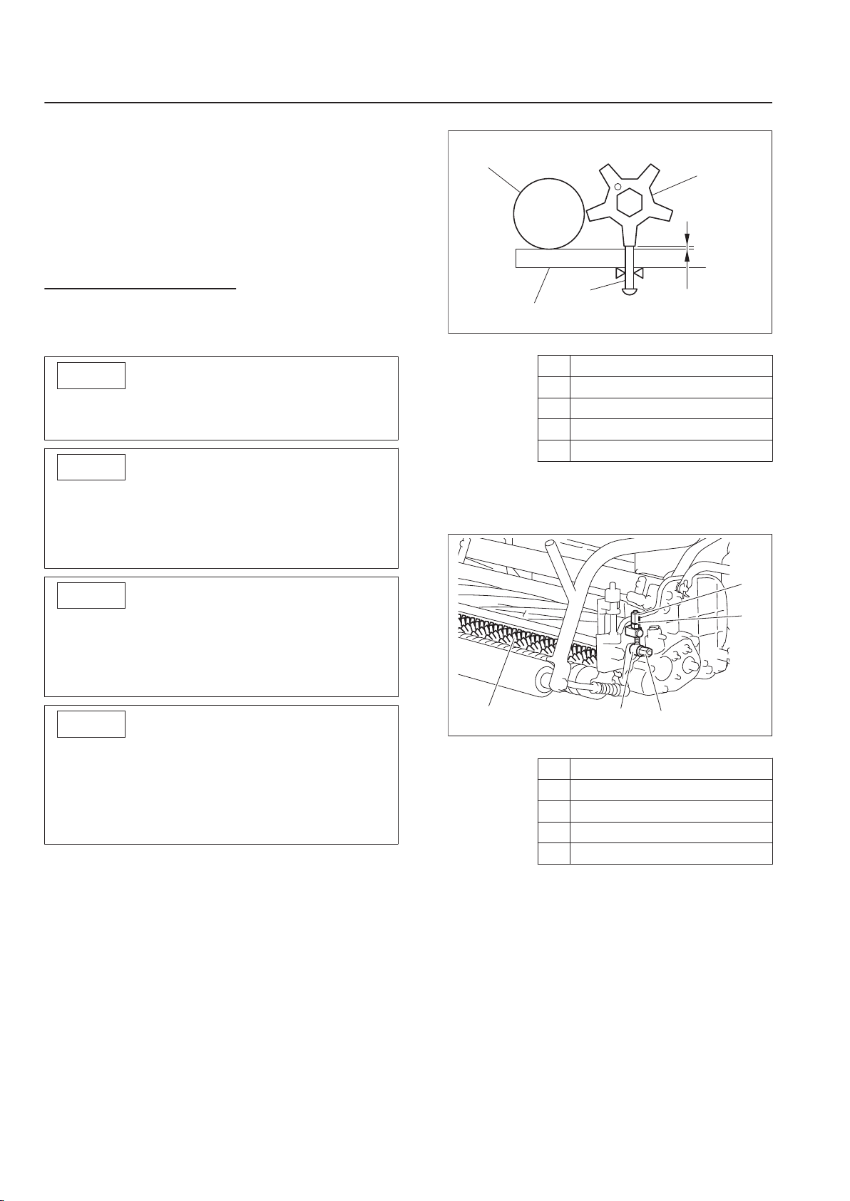
Adjust the engagement between the reel
3.
cutter (cutting cylinder) and the bed knife
(bottom blade) so that newspaper (one
piece) will be cut cleanly by the edge of both
blades when the blades in their entirety
come slightly into contact with each other via
the cutter adjustment nuts.
Insert a strip of newspaper into the space
4.
between the reel cutter (cutting cylinder) and
the bed knife (bottom blade) at an angle of
90 degrees.
Then, rotate the reel cutter (cutting cylinder)
counter-clockwise (when you face the mower
unit from the left) to check the sharpness of
the blades.
Check the sharpness of the entire range
(three or four points from left edge to right) of
the reel cutter (cutting cylinder).
If a gap is created between edges:
・
Loosen (rotate counter-clockwise) the
cutter adjustment nut to apply more
contact pressure between the reel cutter
(cutting cylinder) and the bed knife
(bottom blade).
If the reel cutter (cutting cylinder) is too
・
tight to turn:
Tighten (rotate clockwise) the cutter
adjustment nut to reduce the contact
pressure between the reel cutter (cutting
cylinder) and the bed knife (bottom blade).
If the sharpness is not improved by the
・
adjustment:
Perform back lapping to the reel cutter
(cutting cylinder).
Page 4-12
Adjustment of Blade Engagement_001
Adjustment of Blade Engagement_002
Adjustment Before Operating

1 Cutter adjustment nut
Important
Important
1
2
A
A
33i8xn-002
2 Spring
Adjustment of Cutting Height
Adjust the cutting height to fit your cutting work.
This applies the set cutting height that differs
from the actual cutting height.
Cutting Height and Thickness of Bed Knife (Bottom Blade)
LM101
Handling Instructions
The recommended minimum cutting heights
are based on those of common greens.
They may vary according to the green
conditions and machine specifications.
If the green undulation is hard, set it a little bit
higher in order not to damage the green
surface.
Minimum cutting height is recommended for
each thickness of blade as follows.
Type of blade
Standard blade
Tipped blade
Thickness of
blade
(mm/inch)
1.5 3.0 K2511000270 1.5 Bed knife (bottom blade) 55G Standard
2.0 3.5 K2511000280 2 Bed knife (bottom blade) 55G
2.5 4.0 K2511000050 2.5 Bed knife (bottom blade) 55G
3.0 4.5 K2510000060 3 Bed knife (bottom blade) 62.5-559
5.0 7.0 K2510000160 5 Bed knife (bottom blade) 62.5-559
Recommended
minimum cutting
height (mm/inch)
Handling Instructions
Code Part name Remarks
Cutting Height and Thickness of Bed Knife (Bottom Blade)_001
Standard blade
1
2 Tipped blade
A Thickness of blade
Adjustment Before Operating
Page 4-13

1
2
3
4
3kws2a-018
1
2
3
4
3kws2a-019
4
1
32
C
B
A
3kws2a-020
B
4
1
32
C
A
3kws2a-021
LM101
Handling Instructions
Adjustment of Rear Roller
You can adjust the rear roller by 3 stages.
Adjust the rear roller in a position that suits
your work requirements.
Remove nuts A, washers A, S washers A
1.
and bolts A on the right and left sides.
To obtain desired cutting position,
3.
determine the direction of bolt B and install
the rear roller assy.
Cutting position
Aggressive cutting position
・
Long distance of offset and large angle of
bed knife
Adjustment of Rear Roller_001
Bolt A
1
2 Washer A
3 S washer A
4 Nut A
Remove washers B and nuts B on the right
2.
and left sides, and then remove the rear
roller assy from the frame.
Standard cutting position
・
Adjustment of Rear Roller_002
Rear roller assy
1
2 Bolt B
3 Washer B
4 Nut B
Adjustment of Rear Roller_003
Reel cutter
1
2 Bed knife
3 Rear roller assy
4 Bolt B
A Cutting height
B Offset distance
C Bed knife angle
Adjustment of Rear Roller_004
Reel cutter
1
2 Bed knife
3 Rear roller assy
4 Bolt B
A Cutting height
B Offset distance
C Bed knife angle
Page 4-14
Adjustment Before Operating

42
C
B
A
3
1
3kws2a-022
4
3
2
1
3kws2a-016
2
1
9
3
8
4
5
7
6
A
3kws2a-017
3
A
2
1
3kws2a-007
LM101
Handling Instructions
Less aggressive cutting position
・
Short distance of offset and small angle
of bed knife
Adjustment of Rear Roller_005
Reel cutter
1
2 Bed knife
3 Rear roller assy
4 Bolt B
A Cutting height
B Offset distance
C Bed knife angle
Adjustment of Front Roller
Set the slide caliper to the required cutting
1.
height, adjust the neck position of the
cutting height screw of the cutting height
gauge and securely lock with a wingnut.
Loosen the nut fixing the roller bracket of
2.
right and left.
3.
Set the cutting height gauge to the front
roller and rear roller at the right and left end
of the mower unit.
Adjustment of Front Roller_002
Front roller
1
2 Roller bracket
3 Front groomer
4 Reel cutter (Cutting cylinder)
5 Rear roller
6 Bed knife (Bottom blade)
7 Cutting height gauge
8 Small screw for cutting height
9 Small screw for groomer
A Cutting height
Adjust the front roller up and down by the
4.
roller adjuster to determine the position of
the front roller, in order not to have a gap
with the neck position of the cutting height
screw of the cutting height gauge, at the
edge of the bed knife.
Handling Instructions
Adjustment of Front Roller_001
Front roller
1
2 Roller bracket
3 Roller adjuster
Adjustment Before Operating
4 Nut
Repeat the same process at the opposite
5.
side for the adjustment of cutting height.
Adjustment of Front Roller_003
Bed knife (Bottom blade)
1
2 Small screw for cutting height
3 Cutting height gauge
A Cutting height
Page 4-15
Important
Important
Important
Important
1
4
3
2
A
2qrq2r-002
1
54
2
3
2qrq2r-007
LM101
Handling Instructions
6.
Tighten the nuts that secure the right and
left roller brackets to secure them firmly.
Again, make sure that the cutting height is
7.
at the required position by applying the
cutting height gauge to the front roller and
the rear roller at each edge of right and left
of the mower unit.
Adjustment of Groomer
Note:
Depending on the specifications, this function
may not be available.
Adjust the front groomer according to the
condition of the green before use.
Adjustment of Groomer_001
Dethatching blade
1
2 Small screw for groomer
3 Cutting height gauge
4 Front roller
A Operating height
Set the grooming height more than 0.0 mm
from the ground.
If the groomer blades are set deeper than the
ground surface, the groomer shaft may break.
The front groomer, when it is put too low, may
apply an excessive load to the engine and
transmission section and cause malfunction or
failure.
When using the grooming brush, adjust the
height so that it will be equal to the cutting
height.
The brush will be worn easily when the height
is too low.
1.
Set the slide caliper to the required operating
height, adjust the end of the small screw for
groomer of the cutting height gauge and
securely lock with a wing nut.
Loosen the nuts B fixing the right and left
2.
groomer adjustment screws.
Loosen the right and left special high nuts.
3.
Adjustment of Groomer_002
Front groomer
1
2 High nut
3 Nut A
4 Nut B
5 Groomer adjustment screw
Page 4-16
Adjustment Before Operating

Apply the cutting height gauge to the front
2
1
9
3
8
4
5
7
6
A
3kws2a-017
Important
1
54
2
3
2qrq2r-007
4.
roller and the rear roller at the right and left
edges of the mower unit.
Adjustment of Groomer_003
Front roller
1
2 Roller bracket
3 Front groomer
4 Reel Cutter (Cutting Cylinder)
5 Bed knife (Bottom blade)
6 Rear roller
7 Cutting height gauge
8 Small screw for cutting height
9 Small screw for groomer
A Operation height
Adjust the position so that the small screw for
groomer can contact the dethatching blades.
LM101
Handling Instructions
Adjustment of Groomer_004
Front groomer
1
2 High nut
3 Nut A
4 Nut B
5 Groomer adjustment screw
Note:
In the case that the front groomer is not
used, you do not have to change the set
grooming height.
Loosen the nuts fixing the right and left
groomer adjustment screws, lift the groomer
and tighten the right and left nuts to raise the
front groomer so that it cannot contact the
lawn.
Next time the groomer is used, loosen the
right and left nuts, lower the groomer and
tighten the nuts so that it can return to the
grooming height set previously.
Handling Instructions
Adjust the nuts A up and down so that the
5.
right and left sides can be parallel.
Repeat the same process at the opposite
6.
side for the adjustment of grooming height.
Tighten the nuts B that secure the right and
7.
left groomer adjustment screws.
8.
Tighten the right and left high nuts.
Reconfirm that the grooming height is at the
9.
required position by applying the cutting
height gauge to the front roller and the rear
roller at the right and left edges of the mower
unit.
Adjustment Before Operating
Page 4-17

Warning
Caution
BA
1
v2e27i-035
A
B
1
v2e27i-037
B
2
1
A
v2e27i-040
A
1
B
B
v2e27i-055
BA
1
v2e27i-043
LM101
Handling Instructions
Procedure to Start / Stop Engine
Start / Stop of Engine
Procedure to Start Engine
Before starting the engine, make sure that
there are no other people or obstacles around
the machine.
Make sure that the engine clutch cover is
installed in the prescribed position.
Make sure that the engine switch is in the
1.
"OFF" position.
Don't grip the main clutch lever.
3.
Procedure to Start Engine_003
Main clutch lever
1
2 Safety lock switch
A ON
B OFF
Set the fuel cock to the "Open" position.
4.
Procedure to Start Engine_001
Engine switch
1
A ON
B OFF
Make sure that the brake is locked.
2.
Procedure to Start Engine_002
Brake lever
1
A Lock
B Unlock
Procedure to Start Engine_004
Fuel cock
1
A Close
B Open
Set the engine switch to the "ON" position.
5.
Procedure to Start Engine_005
Engine switch
1
A ON
B OFF
Page 4-18
Procedure to Start / Stop Engine

Shift the throttle lever halfway from low
B
1
A
v2e27i-050
A
A
B
1
v2e27i-056
1
v2e27i-048
A
B
1
B
v2e27i-057
B
2
1
A
v2e27i-040
B
1
A
dgvd7o-002
6.
speed to high speed position.
Procedure to Start Engine_006
Throttle lever
1
A High speed
B Low speed
Set the choke lever to the "Close" position.
7.
Handling Instructions
Set the choke lever to the "Open" position.
9.
Procedure to Start Engine_009
Choke lever
1
A Close
B Open
Procedure to Stop Engine
Don't grip the main clutch lever.
1.
LM101
Handling Instructions
Procedure to Start Engine_007
Choke lever
1
A Close
B Open
Pull the recoil starter, and the engine will
8.
Procedure to Stop Engine_001
Main clutch lever
1
2 Safety lock switch
A ON
B OFF
start.
Set the throttle lever to low speed position.
2.
Procedure to Start Engine_008
1
Recoil starter
Procedure to Stop Engine_002
Procedure to Start / Stop Engine
Page 4-19

BA
1
v2e27i-035
A
1
A
B
dgvd7o-006
Caution
Caution
Caution
Caution
6
7
9
2
3
4
5
8
1
8zq6pd-023
LM101
Handling Instructions
1 Throttle lever
A High speed
B Low speed
Set the engine switch to the "OFF" position.
3.
Procedure to Stop Engine_003
Engine switch
1
A ON
B OFF
Set the fuel cock to the "Close" position.
4.
Cautions before Leaving the Machine
Park the machine on a flat place.
Do not park the machine on a slope.
Check that the engine has stopped.
Make sure that the brake lever is locked.
Description about Operation Decals
Procedure to Stop Engine_004
1
A Close
B Open
Operation of Each Section
Fuel cock
Precautions for Operating the Machine
Under any circumstances drive the machine at
such a speed that you can stop it immediately
Page 4-20
for emergencies.
Description about Operation Decals_001
Engine switch mark
1
2 Decal, accelerator
3 Decal, brake
4 Decal, light switch
5 Sticker, ON/OFF A (Unit clutch)
6 Sticker, ON/OFF A (Drum clutch)
7 Sticker, reel rotation
8 Decal, groomer indication
9 Decal, alignment 10300 (Set of 2pcs)
Operation of Each Section

-
OFF ON
8zq6pd-006
HIGH
LOW
6n6oux-014
6n6oux-092
1
2
6n6oux-086
ON
OFF
8zq6pd-011
1
ENGINE SWITCH MARK
It illustrates the positions of the engine switch.
-
DECAL, ACCELERATOR
2
It illustrates Low/High of the engine rotation speed.
HIGH:High Speed
LOW:Low Speed
LM101
Handling Instructions
Handling Instructions
K4209001200
3
DECAL, BRAKE
It illustrates the locking position for the parking brake.
K4203001610
DECAL, LIGHT SWITCH
Note:
4
Depending on the specifications, this function may
not be available.
It illustrates ON/OFF of the light.
K4203001140
5
STICKER, ON/OFF A
It shows ON/OFF of the unit clutch.
Operation of Each Section
Page 4-21

ON
OFF
8zq6pd-011
8zq6pd-022
Normal
Stop
Reverse
8zq6pd-014
8zq6pd-012
LM101
Handling Instructions
K4203001140
6
STICKER, ON/OFF A
It shows ON/OFF of the drum clutch.
K4203001690
STICKER, REEL ROTATION
It illustrates High / Low clip of the reel cutter rotation
7
speed.
Low: Low Clip
High: High Clip
K4203001120
DECAL, GROOMER INDICATION
Note:
Depending on the specifications, this function may
8
not be available.
It illustrates the changeover of rotational direction of
the groomer.
Normal: Normal rotation
Reverse: Reverse rotation
K4209001230
DECAL, ALIGNMENT 10300 (SET OF 2PCS)
Note:
9
Depending on the specifications, this function may
not be available.
Affix the decal in indicative positions for operational
support.
Page 4-22
Operation of Each Section

A
B
1
bnec97-022
BA
1
v2e27i-035
B
1
A
v2e27i-045
Important
A
B
1
v2e27i-037
LM101
Handling Instructions
Light Switch
Note:
Depending on the specifications, this function
may not be available.
The light switch is located in the handle panel.
Flip up the switch to turn on the light, and down
to turn off.
Light Switch_001
Light switch
1
A ON
B OFF
Engine Switch
The factory default engine rpm (maximum) is
set to 3,100 rpm.
Operate at about 3,000 rpm.
Throttle Lever_001
Throttle lever
1
A High speed
B Low speed
Brake Lever
Avoid quick operation.
Carefully and slowly operate the machine.
Handling Instructions
The engine switch is located in the handle.
To start the engine, set the engine switch to
the “ON” position, and to stop it, set to the
“OFF” position.
Engine Switch_001
Engine switch
1
A ON
B OFF
Throttle Lever
The throttle lever is located in the handle and
enables you to adjust the engine rpm.
Move the throttle lever toward HIGH (high
speed) to increase the engine rpm, and toward
LOW (low speed) to reduce the rpm.
Note:
Operation of Each Section
The brake lever is located in the handle.
Pull up the brake lever to activate braking and
the travel of the machine is stopped.
Pull the brake lever up to the top and the brake
lever is locked with brake applied.
Push down the brake lever to release the
brake.
Note:
Lock the brake lever to apply Parking Brake.
Brake Lever_001
Brake lever
1
A Lock
B Unlock
Page 4-23

Important
A
B
2
1
6zsd1y-001
Important
Important
B
2
1
A
k7k67l-002
Caution
1
dckng4-001
LM101
Handling Instructions
Safety Lock Switch
The safety lock switch is located in the handle.
While the main clutch is in the "OFF" position,
the safety lock is activated.
Grip the main clutch lever while pushing the
safety lock switch to unlock the safety lock.
Main Clutch Lever_001
1
2 Safety lock switch
A ON
B OFF
Drum Clutch Lever
Main clutch lever
Safety Lock Switch_001
Main clutch lever
1
2 Safety lock switch
A Lock
B Unlock
Main Clutch Lever
Avoid quick operation.
Carefully and slowly operate the machine.
The main clutch is not activated unless the
safety lock released.
The main clutch lever is located in the handle.
Unlock the safety lock and then grip the main
clutch lever to traveling forward with rotating
the reel cutter.
Release the main clutch lever from the hands
to stop the machine traveling and the reel
cutter rotating.
Operate and set the lever to the proper
position in accordance with the purpose when
the main clutch lever set to the OFF position.
The drum clutch lever is located at the rear of
the right frame side.
Set the lever to ON to activate the drum and
the traveling wheels.
Set the lever to OFF for neutral.
Drum Clutch Lever_001
Drum clutch lever
1
Note:
The machine can be moved easily with the
lever OFF when the engine stopped.
Page 4-24
Operation of Each Section

Caution
ON
1
OFF
xzqhpm-001
Caution
1
B
A
C
el1q3z-002
1
2
paspfk-003
LM101
Handling Instructions
Unit Clutch Lever
Operate and set the lever to the proper
position in accordance with the purpose when
the main clutch lever set to the OFF position.
The unit clutch lever is located above the left
frame.
Set the lever to the ON position and the power
is transmitted from the transmission case to the
unit.
Set the lever to the OFF position and the
power from the transmission case to the unit is
cut off.
This is suitable for the work when the turf
condition is not so good.
When the lever is shifted to "Stop", the drive
transmission for the reel rotation gear is
disengaged.
FOC (High/Low Clip) Selector Lever_001
FOC (High/Low clip) Selector Lever
1
A High clip
B Low clip
C Stop
Handling Instructions
Engine Clutch Cover
The engine clutch cover is on the left side of
the engine, covering the engine clutch.
The engine clutch cover can be opened and
Unit Clutch Lever_001
Unit clutch lever
1
closed with the fastening bolt taken off and put
on.
Note:
Set the lever to the OFF position when
traveling.
FOC (High/Low Clip) Selector Lever
Operate and set the lever to the proper
position in accordance with the purpose when
the main clutch lever set to the OFF position.
Engine Clutch Cover_001
The FOC (High/Low Clip) selector lever is in
the right side of the unit.
There are three changeover positions.
When the lever is shifted to "High clip", the reel
cutter (cutting cylinder) rotates faster, and the
clip pitch (cutting interval) becomes shorter.
This is suitable for the work in good turf
condition.
When the lever is shifted to "Low clip", the reel
cutter (cutting cylinder) rotates slower
compared to "High clip" and the clip pitch
becomes longer.
Operation of Each Section
Engine Clutch Cover
1
2 Fastening bolt
Page 4-25
Caution
1
BA
C
aqilnf-003
1
2
uknn6v-002
Warning
LM101
Handling Instructions
Groomer Clutch Lever
Note:
Depending on the specifications, this function
may not be available.
Operate and set the lever to the proper
position in accordance with the purpose when
the main clutch lever set to the OFF position.
The groomer clutch lever is in the left side of
the unit.
There are three changeover positions.
When the lever is in the "Normal rotation"
position, the groomer rotates in the same
direction as the blade reel cylinder.
When the lever is in the "Reverse rotation"
position, the groomer rotates in the opposite
direction of the blade reel cylinder.
When the lever is in the "Rotation stop"
position, the groomer does not rotate.
Instruments
Hour Meter
The hour meter is located in the operation
panel, and indicates the accumulated operation
time of the engine.
It accumulates time up to 9999:59 and then the
count automatically returns to 0000:00.
Hour Meter_001
Hour meter
1
2 Antenna lead wire
Groomer Clutch Lever_001
Groomer clutch lever
1
A Normal rotation
B Reverse rotation
C Rotation stop
Travel of Machine
Traveling the Machine
Do not start to move or stop the machine
abruptly.
Install traveling tires.
1.
Flip up the stand.
2.
Set the drum clutch lever to "ON" position.
3.
Start the engine.
4.
Release the brake.
5.
Release the safety lock and grip the main
6.
clutch lever slowly.
The machine can start traveling.
7.
Page 4-26
Instruments

Warning
Caution
Caution
Caution
Important
1
2
x9pzjh-006
1
2
x9pzjh-002
1
x9pzjh-007
LM101
Handling Instructions
Cutting Work
Cutting Work
Do not start to move or stop the machine
abruptly.
Do not operate on a steep slope.
Be sure to operate at an appropriate speed for
the mowing site.
For mowing on an undulated surface, mow
with lowered cutting speed.
Be sure to attach the grass catcher.
Discharge the clippings at the right time during
operation.
Traveling tires are used to travel.
Removing Traveling Tires:
1.
Stop the engine.
2.
Flip down the stand.
Removing/Installing Traveling Tires_001
Stand
1
2 Traveling tire
While holding the lever of the wheel mount
3.
plate to the release position, pull the
traveling tire toward to remove it.
Handling Instructions
Remove the traveling tires.
1.
Flip up the stand.
2.
Install the grass catcher.
3.
Move the FOC (High/Low Clip) selector lever
4.
to the desired position.
Move the drum clutch lever to the "ON"
5.
position.
Move the groomer clutch lever to the desired
6.
position.
Move the Unit clutch lever to the "ON"
7.
position.
Start the engine.
8.
9.
Release the brake.
Release the safety lock and grip the main
10.
clutch lever slowly to start mowing.
Note:
The factory default maximum engine rotation
speed is set to 3,100 rpm.
Operate at about 3,000 rpm.
Removing/Installing Traveling Tires
Removing/Installing Traveling Tires_002
Traveling tire
1
2 Wheel mount plate
Remove the traveling tires before cutting
work.
Cutting Work
Removing/Installing Traveling Tires_003
Traveling tire
1
Repeat the same process for removing the
4.
opposite traveling tire.
Page 4-27

Important
1
A
A
2
x9pzjh-008
Important
1
2
A
x9pzjh-005
Caution
2
1
bos35l-005
LM101
Handling Instructions
Installing Traveling Tires:
The drum shaft and the traveling tires have
mating parts each other.
Make sure of their shapes to install the
traveling tires.
Removing/Installing Traveling Tires_004
Traveling tire
1
2 Drum shaft
A Mating parts
Removing/Installing Grass Catcher
Stop the engine before removing/installing the
grass catcher.
Removing Grass Catcher:
Lift up the grass catcher and remove it from
the grass catcher fitting bars.
Installing Grass Catcher:
Insert the grass catcher fitting bars into the
slots of the grass catcher.
Make sure that the wheel mount plate is
grooved on the drum shaft.
Otherwise the tires may come off.
Removing/Installing Traveling Tires_005
Traveling tire
1
2 Wheel mount plate
A Groove
When installing traveling tires, follow the
reverse procedure to removing.
Removing/Installing Grass Catcher_001
Grass catcher
1
2 Grass catcher fitting bar
Page 4-28
Cutting Work

Transporting
Caution
Important
Important
Transporting Procedure
When loading and unloading the machine,
wear non-slip shoes and travel slowly.
When securing the machine with a rope, do
not tie the rope to the engine.
When securing the machine with a rope, be
careful not to bend any wires.
LM101
Handling Instructions
Handling Instructions
Be extremely careful when loading the
machine into a truck or a trailer.
Before loading or unloading, stop the truck or
trailer on a level surface in a safe location,
apply the parking brake, stop the engine, and
then chock the wheels.
Before loading into a truck or a trailer for
transportation, apply the parking brake of the
machine, stop its engine, and then secure the
machine with rope or any other sufficiently
strong restraining device.
When using a loading ramp, select one of
sufficient length, width and strength, and that
will not allow the machine to slip off.
Transporting
Page 4-29

LM101
Handling Instructions
Page 4-30
Transporting

Maintenance Precautions ..................... Page 5-2
Position of mower during
maintenance .......................................... Page 5-2
Maintenance Schedule .......................... Page 5-4
Specified Values ....................................Page 5-6
Greasing ................................................. Page 5-7
About Greasing ......................................Page 5-7
Greasing Points ..................................... Page 5-7
Maintenance (Mower) .......................... Page 5-10
LM101
Maintenance
Adjustment of Cutter Adjustment
Spring .................................................. Page 5-10
Adjusting CAM .....................................Page 5-11
Back Lapping of Reel Cutter
(Cutting Cylinder) .................................Page 5-12
Sharpening of Reel Cutter (Cutting
Cylinder) .............................................. Page 5-14
Replacement of Reel Cutter (Cutting
Cylinder) .............................................. Page 5-15
Replacement of Bed Knife (Bottom
Blade) .................................................. Page 5-17
Removing/Installing The Bed Knife
Base .....................................................Page 5-17
Removing/Installing The Bed Knife ..... Page 5-21
Maintenance (Main Body) ................... Page 5-23
Adjustment of Brake ............................ Page 5-23
Adjustment of Engine Clutch ............... Page 5-23
Change of Air Cleaner ......................... Page 5-24
Replacement of Engine Oil ..................Page 5-25
Maintenance
Long-Term Storage ..............................Page 5-25
Before Long-Term Storage ..................Page 5-25
Troubleshooting Procedures of
Aftercut Appearance ........................... Page 5-26
Scalping ...............................................Page 5-26
Angled Mismatch ................................. Page 5-26
Overlap Marks ..................................... Page 5-27
Blade does not cut. ..............................Page 5-28
Uneven Blade Engagement .................Page 5-29
Page 5-1

Caution
Caution
Caution
Important
Important
Caution
ucqx4p-001
LM101
Maintenance
Maintenance Precautions
First, learn well the maintenance operations
you plan to perform.
Use tools appropriate for each maintenance
operation.
For the safe and best performance of your
machine, use Baroness genuine parts for
replacement and accessories.
Please note that our product warranty may be
void if you use non-genuine parts for
replacement or accessories.
Pay attention to the machine standing up with
the maintenance stand lifted up when large
power is added to the mower unit of the
machine tilting toward the handle side.
Park the machine on a level place.
1.
Tilt it slowly toward the handle side and
2.
pass the handle grip through the hollow
cylinder pipe of the maintenance stand.
Set the handle so that the maintenance
3.
stand can stand upright.
Position of mower during maintenance
If the mower handle is left leaned on the
ground for a long time during maintenance
engine oil may enter the engine combustion
chamber and cause the engine to run
improperly.
Be careful not to keep this position long and
ensure sufficient time for any oil to drain back
by returning to upright position for ten minutes
before starting.
An attitude of the machine tilting toward the
handle side at a large angle may cause the
engine malfunction.
Note:
The attitude of the machine tilting toward the
handle side at a large angle is a state where
the engine tilts more than 30 degrees from the
upright position.
For maintenance of the machine fitted with
・
the traveling wheels:
Use the maintenance stand to prevent from
the engine malfunction.
Position of mower during maintenance_001
Maintenance stand
1
Page 5-2
Maintenance Precautions

For maintenance of the machine without the
Caution
ucqx4p-002
・
traveling wheels:
The engine malfunction does not occur even
when the machine tilting toward the handle
side with the stand touching the ground.
Pay attention to the machine standing up
depending on the unbalanced state owing to
the adjusted position of the handle height.
Park the machine on a level place.
1.
Tilt it slowly toward the handle side and
2.
set it so that the stand can touch the
ground.
LM101
Maintenance
Maintenance
Position of mower during maintenance_002
Maintenance Precautions
Page 5-3

LM101
Maintenance
Maintenance Schedule
LM101
Follow the maintenance schedule below.
○・・・Inspect, adjust, supply, clean
●・・・Replace (first time)
△・・・Replace
Maintenance Item
After Work
Before Work
*2 Check tightening bolts and nuts ○
*2 Check fuel level ○
Check fuel and oil leaks ○
*2 Check engine oil level ○
*2 Check air cleaner ○
Clean engine and circumference
*2 Change engine oil ● △ 20 hours first change
*2 Check spark plug ○
*2 Clean spark arrester ○
*2 Clean sediment cup ○
*1 Clean fuel tank & filter ○
*1 Check idling speed ○ ○
Engine
*1 Check valve clearance ○ ○
*2 Replace air cleaner △ △
*2 Replace spark plug △ △
*1
*1
Check damaged parts ○
Main body
Check tightening bolts and nuts ○
of the muffler cover
Remove carbon in combustion
chamber
Check fuel hoses and clamp
bands
Check tire pressures and
condition
○
○
○ Replace as necessary.
○
Every 10 hrs.
Every 20 hrs.
Every 25 hrs.
Every 50 hrs.
Every 100 hrs.
Every 300 hrs.
Every year
Every 500 hrs.
Every 2 years
When Required
Check every 300 hours
or every year whichever
Check every 300 hours
or every year whichever
whichever comes earlier
whichever comes earlier
Remarks
comes earlier
comes earlier
Paper filter element:
Replace every 300
hours or every year
Foam filter element:
Replace as necessary
Replace every 300
hours or every year
Refer to "Inspection of
Tires"
Page 5-4
Maintenance Schedule

LM101
Maintenance
Maintenance Item
After Work
Before Work
Check brake function ○
Check work lamp illumination ○
Adjust handle position ○
Check safety lock of main clutch ○
Check cover condition ○
Clean machine exterior ○
Adjust engine clutch spring ○
Main body
Check brake wire ○
Adjust engine clutch gap ○
Check throttle wire ○
Check main clutch wire ○
Check cover condition ○
Check roller condition ○
Check groomer condition ○
Engage blades ○
Mower unit
Check mowing height ○
Adjust groomer ○
Check damaged parts ○
Check tightening bolts and nuts ○
Clean mower unit ○
Check main clutch lever
actuation
Grease and Lubricate all moving
parts
Check electrical wiring condition
(Damage, defacement and joint
looseness)
Check blade condition (Reel
cutter and Bedknife)
○
○ ○
○
○
Every 10 hrs.
Every 20 hrs.
Every 25 hrs.
Every 50 hrs.
Every 100 hrs.
Every 300 hrs.
Every year
Every 500 hrs.
Every 2 years
When Required
Refer to "Inspection of
Brake""Adjustment of
Refer to "Adjustment of
Refer to "Greasing
Refer to "Adjustment of
Engine Clutch"
Refer to "Inspection of
Replace as necessary.
Refer to "Adjustment of
Engine Clutch"
Refer to "Inspection of
Refer to "Inspection of
Refer to "Inspection of
Reel Cutter (Cutting
Cylinder) and Bed Knife
(Bottom Blade)"
Refer to "Adjustment of
Blade Engagement"
Refer to "Adjustment of
Cutting Height"
Refer to "Adjustment of
Remarks
Brake"
Handle"
Maintenance
Points"
Wire"
Wire"
Wire"
Groomer"
Maintenance Schedule
Page 5-5

LM101
Maintenance
Maintenance Item
After Work
Before Work
Grease ○ ○
Replace front/rear roller bearings △
Replace oil seals inside gearcase △
Replace front/rear roller oil seals △
Mower unit
Replace grease inside gearcase △
Adjust cutter adjustment spring ○
Backlap blades ○
Clean and Grease Bedknife
Eccentric Bushes
Replace bearings inside
gearcase
Replace grass catcher roller
bearings
Replace grass catcher roller oil
seals
Regrind blades (Reel cutter and
Bed knife)
○
△
△
△
○
Every 10 hrs.
Every 20 hrs.
Every 25 hrs.
Every 50 hrs.
Every 100 hrs.
Every 300 hrs.
Every year
Every 500 hrs.
Every 2 years
When Required
Refer to "Greasing
Refer to "Adjustment of
Cutter Adjustment
Refer to "Back Lapping
of Reel Cutter (Cutting
Regrind/Replace blades
as and when required
Remarks
Points"
Spring"
Cylinder)"
*1: Consult your local Baroness Dealer for this service.
・
*2: Refer to the Engine's Owner's Manual.
・
The values for consumables are not guaranteed.
・
Specified Values
Fuel tank capacity
Engine oil capacity
Engine plug - NGK BPR4ES
Tire pneumatic pressure
Cutter adjustment spring 43.0 mm (1.69 in) Total length of spring
Reel cutter shaft bearing preload
spring
Reel cutter rotation torque 0.8 - 1.0 N・m (8 - 10 kgf・cm)
Engine clutch 0.5 - 1.0 mm (0.020 - 0.039 in)
Operation distance of clutch plate 1.0 - 2.0 mm (0.039 - 0.079 in)
Engine clutch spring 61.0 mm (2.40 in) Total length of spring
2.0 dm3 (2.0 L)
0.56 dm3 (0.56 L)
120 kPa (1.2 kgf/cm2)
11.5 mm (0.453 in) Total length of spring
Gasoline
SAE30 (API Service Grade SE or
higher)
4.10/3.50 - 6
Gap between engine clutch and
clutch facing
Page 5-6
Maintenance Schedule

6
7
14
12
12
11
15
14
9
10
8
2
3
5
4
13
1
8bq62b-316
B
8bq62b-298
B
8bq62b-299
LM101
Maintenance
Greasing
About Greasing
Since there may be adhesion or damage due
to lack of grease on moving parts, they must
be greased.
Add urea-based No. 2 grease in accordance
with the Maintenance Schedule.
Other locations where the specified grease or
lubricant is used are indicated in "Greasing
Points".
Add grease using the specified grease or
lubricant.
Greasing Points
Grease nipples are installed in the following
locations.
No. of
1 Upper side of left frame cover 1 B
2 Mower #1 shaft 1 B
3 Left frame #2 shaft 1 A
4 Left frame #4 shaft 1 A
5 Differential gear 1 A
6 Right frame #2 shaft 1 A
7 Right gear case 1 A
8 Transmission gear case 1 A
9 Transmission shaft 2 A
10 Arm mounting hitch fulcrum 1 B
11 Reel housing 2 A
12 Front roller 2 B
13 Groomer gear case 3 A
14 Groomer shaft 2 B
15 Handle 3 B
Location
greasing
points
Greasing
period
Add grease to A every 10 hours, and B every
50 hours.
Upper side of left frame cover
1.
Maintenance
Greasing
Greasing Points_001
Greasing Points_002
Mower #1 shaft
2.
Greasing Points_003
Page 5-7

A
8bq62b-300
A
8bq62b-301
A
8bq62b-302
A
8bq62b-303
A
8bq62b-304
A
8bq62b-305
A
8bq62b-306
LM101
Maintenance
Left frame #2 shaft
3.
Right gear case
7.
Left frame #4 shaft
4.
Differential gear
5.
Greasing Points_004
Greasing Points_005
Greasing Points_008
Transmission gear case
8.
Greasing Points_009
Transmission shaft
9.
There are one location each on the right and
left.
Left side
Right frame #2 shaft
6.
Page 5-8
Greasing Points_006
Greasing Points_007
Greasing Points_010
Greasing

A
8bq62b-307
B
8bq62b-308
A
8bq62b-309
A
8bq62b-310
B
8bq62b-311
B
8bq62b-312
LM101
Maintenance
Right side
Greasing Points_011
Arm mounting hitch fulcrum
10.
Right side
Greasing Points_014
Front roller
12.
There are one location each on the right and
left.
Left side
Maintenance
Greasing Points_012
Reel housing
11.
There are one location each on the right and
left.
Left side
Greasing Points_013
Greasing Points_015
Right side
Greasing Points_016
Greasing
Page 5-9

A
A
A
8bq62b-313
B
8bq62b-314
B
8bq62b-315
B
B
B
8bq62b-317
Caution
Caution
LM101
Maintenance
Groomer gear case
13.
Note:
Depending on the specifications, this
function may not be available.
Handle
15.
Main clutch lever
・
・
Brake lever
・
Safety lock switch
Greasing Points_017
Groomer shaft
14.
Note:
Depending on the specifications, this
function may not be available.
There are one location each on the right and
left.
Left side
Greasing Points_018
Right side
Greasing Points_020
Maintenance (Mower)
Adjustment of Cutter Adjustment Spring
Both the reel cutter (cutting cylinder) and the
bed knife (bottom blade) are edged tools.
Handle them carefully, since they could cut
your hands and feet.
When handling the reel cutter (cutting
cylinder) and the bed knife (bottom blade),
wear gloves to protect your hands.
Pay attention not to let the reel cutter (cutting
cylinder) catch your gloves. Otherwise, you
may injure your hand or fingers.
If the diameter of the reel cutter (cutting
cylinder) becomes smaller, adjust the cutter
adjustment spring.
Adjust the blade engagement.
1.
Page 5-10
Greasing Points_019
Maintenance (Mower)

Loosen the spring adjusting screw and the
A
2
3
1
tv9pml-005
1
2
3
A
B
C
ippmes-002
2.
nut, and then adjust the length of the coil
spring to 43.0 mm (1.69 in).
Adjustment of Cutter Adjustment Spring_001
Spring adjusting screw
1
2 Nut
3 Spring
A 43.0 mm (1.69 in)
Maintenance
Adjusting CAM_001
Center of cutter pin
1
2 Center of cam bush
3 Punch mark
A 0.1 mm (0.004 in)
B Raising the bed knife
C Lowering the bed knife.
LM101
Maintenance
Adjusting CAM
Turn the cam bush on both sides of the bottom
blade, and the blade can be raised and
lowered respectively by maximum 0.1 mm
(0.004 in).
The above method is used when the edges of
the reel cutter (cutting cylinder) and the bed
knife (bottom blade) are not in parallel.
Note:
The figure below shows the situation when you
see from the left frame.
The right frame is mirror reversed.
When the gap at the left frame side between
the reel cutter (cutting cylinder) and the bed
knife (bottom blade) appears.
Loosen the locknut and turn the left cam
1.
bush clockwise to eliminate only the gap
distance.
When you raise the bed knife (bottom
blade) by 0.1 mm (0.004 in), turn the left
cam bush clockwise 30 degrees.
Once the adjustment completed, tighten
2.
the locknut securely.
When the gap at the right frame side
between the reel cutter (cutting cylinder) and
the bed knife (bottom blade) appears.
Loosen the locknut and turn the right cam
1.
2.
bush anticlockwise to eliminate only the
gap distance.
Once the adjustment completed, tighten
the locknut securely.
Maintenance (Mower)
Page 5-11

Caution
Caution
Caution
1 2 3 4
zhz6po-002
Caution
Important
A
B
C
1
zhz6po-009
LM101
Maintenance
Back Lapping of Reel Cutter (Cutting Cylinder)
Back lapping is work similar to sharpening a
cooking knife. If the edges of the reel cutter
(cutting cylinder) and the bed knife (bottom
blade) become blunt and make cutting difficult,
both the reel cutter (cutting cylinder) and the
bed knife (bottom blade) should be
simultaneously sharpened by reversing the reel
cutter (cutting cylinder) with an abrasive paste
applied.
However, back lapping is a temporary measure
and would not restore the sharpness
completely.
If the edges of the reel cutter (cutting cylinder)
and the bed knife (bottom blade) become blunt
and make cutting difficult, follow the steps
below to perform back lapping.
Both the reel cutter (cutting cylinder) and the
bed knife (bottom blade) are edged tools.
Handle them carefully, since they could cut
your hands and feet.
1 Newspaper
2 Back lapping powder
3 Gel compound
4 Brush
Note:
The mixing ratio for the abrasive, in volume,
is one part back lapping powder (#200 #400) to three or four parts oil.
Have a lapping machine or the lapping
2.
handle ready.
When handling the reel cutter (cutting
cylinder) and the bed knife (bottom blade),
wear gloves to protect your hands.
Pay attention not to let the reel cutter (cutting
cylinder) catch your gloves. Otherwise, you
may injure your hand or fingers.
Check the sharpness of the blade by checking
the blade engagement after cutting grass.
During back lapping, the reel cutter (cutting
cylinder) rotates.
Keep hands and feet away from moving parts.
Do not perform back lapping with any other
persons.
Have the following items ready: Strips of
1.
newspaper, Abrasive [Back lapping powder
mixed with oil; or gel compound (Baroness
genuine abrasive)], Brush.
Stop the engine.
3.
Shift the the FOC (High/Low Clip) selector
4.
lever to the "Stop" position.
Back Lapping of Reel Cutter (Cutting Cylinder)_002
FOC (High/Low clip) Selector Lever
1
A High clip
B Low clip
C Stop
Back Lapping of Reel Cutter (Cutting Cylinder)_001
Page 5-12
Maintenance (Mower)

1
A
2
zhz6po-005
1
zhz6po-010
1
zhz6po-011
Important
zhz6po-012
LM101
Maintenance
Insert one or two strips of newspaper into the
5.
space between the reel cutter (cutting
cylinder) and the bed knife (bottom blade) at
an angle of 90 degrees. Then, rotate the reel
cutter (cutting cylinder) counter-clockwise
(when you face the mower unit from the left)
by hand to check the sharpness of the
blades.
Back Lapping of Reel Cutter (Cutting Cylinder)_003
Reel cutter
1
2 Bed knife
A Rotation direction
Check the sharpness of the entire range
6.
(three or four points from the left edge to the
right one) of the reel cutter (cutting cylinder).
Using a piece of chalk, mark locations on the
7.
blade that are sharp.
8.
Connect the lapping machine or the lapping
handle to the lapping bolt on the machine.
Back Lapping of Reel Cutter (Cutting Cylinder)_005
Lapping bolt
1
Rotate the reel cutter (cutting cylinder)
9.
clockwise (when you face the mower unit
from the left).
Turn on the lapping machine.
・
Or rotate the lapping handle.
・
The right side of the reel cutter (when you
face the mower unit from the front) is inclined
to wear earlier than the left side. Accordingly
be sure to move the brush from the left to the
right to apply the abrasive.
Maintenance
Back Lapping of Reel Cutter (Cutting Cylinder)_004
Maintenance (Mower)
Lapping machine
1
Back Lapping of Reel Cutter (Cutting Cylinder)_006
Apply the abrasive evenly with the brush on
10.
the top side of reel cutter (cutting cylinder)
where the newspaper was cut well or of
chalk-marked locations.
(Never apply to blunt areas.)
Rotate the reel cutter for a while and stop its
11.
rotation when the sound of contact is lost.
Turn off the lapping machine.
・
Or stop rotating the lapping handle.
・
Disconnect the lapping machine or the
12.
lapping handle (accessory tool).
Page 5-13

Important
Caution
Caution
B
A
1
2
3
ok5ueg-006
LM101
Maintenance
Wash off or wipe off with a cloth, etc., the
13.
abrasive from the reel cutter (cutting
cylinder), and then check it for sharpness.
Repeat steps 5 to 13 until the entire range
14.
(three or four points from the left edge to the
right one) of the reel cutter (cutting cylinder)
is uniformly sharpened.
15.
Finally, apply abrasive to the entire blade
width of the reel cutter (cutting cylinder) and
perform final back lapping.
Pay attention not to pour water over the
engine and electric components when
cleaning.
Wash out the abrasive with a washer etc.
16.
While checking the blade for sharpness,
17.
adjust blade engagement.
Sharpening of Reel Cutter (Cutting Cylinder)
For sharpening the reel cutter (cutting
cylinder), contact your dealer or Baroness.
If the outer diameter of the reel cutter (cutting
cylinder) after sharpening is more than the
usage limit, the reel cutter (cutting cylinder) can
be sharpened.
New Usage limit
Dimension B
Dimension A
(Outer
diameter of
reel cutter
(cutting
cylinder))
101 mm 37.8 mm 93 mm 33.8 mm
(Distance
from blade
edge to
outer edge
of reel cutter
(cutting
cylinder)
shaft)
Dimension A
(Outer
diameter of
reel cutter
(cutting
cylinder))
Dimension B
(Distance
from blade
edge to
outer edge
of reel cutter
(cutting
cylinder)
shaft)
Note:
The outer diameter of the reel cutter (cutting
cylinder) shaft is 25.4 mm.
Both the reel cutter (cutting cylinder) and the
bed knife (bottom blade) are edged tools.
Handle them carefully, since they could cut
your hands and feet.
Wear gloves when touching edged tools to
avoid cutting your hands.
The sharpening of the reel cutter (cutting
cylinder) consists in maintaining its roundness
and creating a relief (second edge face).
This work should be performed if the
sharpness cannot be restored, even after back
lapping, or if the relief (second edge face) has
worn away.
Sharpen the reel cutter (cutting cylinder) when
the sharpness cannot be restored, even after
back lapping, or when the relief (second edge
face) has worn away, there is full contact or
back lapping takes too much time.
In addition, if the reel cutter (cutting cylinder)
becomes worn and its shape conical, perform
cylindrical grinding to return it to a cylindrical
shape.
Sharpening of Reel Cutter (Cutting Cylinder)_001
Reel cutter (cutting cylinder) blade
1
2 Reel cutter (cutting cylinder) disc
3 Reel cutter (cutting cylinder) shaft
Outer diameter of reel cutter (cutting
A
cylinder)
Distance from blade edge to outer
B
edge of reel cutter (cutting cylinder)
shaft
Page 5-14
Maintenance (Mower)

A
1
ok5ueg-007
Caution
Caution
B
A
1
2
3
ok5ueg-006
LM101
Maintenance
Sharpening is necessary when the reel cutter
(cutting cylinder) reaches a condition described
below.
When the sharpening width (length of
1.
contacting surface of bed knife (bottom
blade)) for the outer diameter of the reel
cutter (cutting cylinder) is greater than the
usage limit.
Outer diameter of reel
cutter (cutting cylinder)
(new part)
101 mm
Usage limit of
sharpening width for
outer diameter of reel
cutter (cutting cylinder)
2.5 mm (factoryrecommended)
The criteria for replacing the reel cutter (cutting
cylinder) are described below.
However, these criteria are only a reference
and do not guarantee performance like that of
a new reel cutter (cutting cylinder).
When the outer diameter of the reel cutter
1.
(cutting cylinder) is less than the usage limit
New Usage limit
Dimension B
Dimension A
(Outer
diameter of
reel cutter
(cutting
cylinder))
101 mm 37.8 mm 93 mm 33.8 mm
(Distance
from blade
edge to
outer edge
of reel cutter
(cutting
cylinder)
shaft)
Dimension A
(Outer
diameter of
reel cutter
(cutting
cylinder))
Dimension B
(Distance
from blade
edge to
outer edge
of reel cutter
(cutting
cylinder)
shaft)
Note:
The outer diameter of the reel cutter (cutting
cylinder) shaft is 25.4 mm.
Maintenance
Sharpening of Reel Cutter (Cutting Cylinder)_002
Reel cutter (cutting cylinder) blade
1
Sharpening width for outer diameter of
A
reel cutter (cutting cylinder)
When the edges become blunt or the blade
2.
edge cannot be formed with back lapping
When the reel cutter (cutting cylinder)
3.
becomes worn and its shape conical, or
when blade engagement adjustment cannot
be performed
Replacement of Reel Cutter (Cutting Cylinder)
Both the reel cutter (cutting cylinder) and the
bed knife (bottom blade) are edged tools.
Handle them carefully, since they could cut
your hands and feet.
Wear gloves when touching edged tools to
avoid cutting your hands.
Replacement of Reel Cutter (Cutting Cylinder)_001
Reel cutter (cutting cylinder) blade
1
2 Reel cutter (cutting cylinder) disc
3 Reel cutter (cutting cylinder) shaft
Outer diameter of reel cutter (cutting
A
cylinder)
Distance from blade edge to outer
B
edge of reel cutter (cutting cylinder)
shaft
Maintenance (Mower)
Page 5-15

Caution
Caution
Caution
Important
A
2
1
3
wggg9e-017
A
2
1
3
wggg9e-018
LM101
Maintenance
Installing The Reel Cutter
Both the reel cutter (cutting cylinder) and the
bed knife (bottom blade) are edged tools.
Handle them carefully, since they could cut
your hands and feet.
When handling the reel cutter (cutting
cylinder) and the bed knife (bottom blade),
wear gloves to protect your hands.
Pay attention not to let the reel cutter (cutting
cylinder) catch your gloves. Otherwise, you
may injure your hand or fingers.
See the list in Tightening torques.
Note that the Baroness product warranty may
not apply to defects caused by incorrect or
overtorque tightening etc.
Mower without Groomer:
Installing The Reel Cutter_001
Collar
1
2 Nut
3 Torque wrench
A 11.5 mm (0.453 in)
Mower with Groomer:
Follow the instruction below to replace the
reel cutter bearing and oil seal on both sides.
Use Bearing 30204JRP6.
Fill up the bearings and oil seals with
1.
grease (Excelite EP No.2).
Attach the reel cutter (cutting cylinder) to
2.
the frame.
Tighten the nut completely and temporarily,
3.
and then loosen it until the spring length
reaches 11.5 mm(0.453 in)and lock it.
Note:
A certain preload will be applied by the
spring pressure.
Measure the rotational torque of the blade
4.
reel cylinder with a torque wrench.
The specified value should be 0.8 to 1.0 N
m (8 to 10 kgf cm).
Installing The Reel Cutter_002
Reel gear
1
2 Gear nut
3 Torque Wrench
A 11.5 mm (0.453 in)
Page 5-16
Maintenance (Mower)

Replacement of Bed Knife (Bottom Blade)
Caution
Caution
A
2
1
d5gd5v-002
Caution
Caution
1
1
2
3
5ttm1g-005
1
5ttm1g-006
Both the reel cutter (cutting cylinder) and the
bed knife (bottom blade) are edged tools.
Handle them carefully, since they could cut
your hands and feet.
Wear gloves when touching edged tools to
avoid cutting your hands.
LM101
Maintenance
While operations are performed with the front
of the machine raised, there is a danger of it
falling.
Securely support the machine.
Lower the roller bracket so that it does not
1.
contact the reel cover, and then remove the
bolts.
The criteria for replacing the bed knife (bottom
blade) are described below.
However, these criteria are only a reference
and do not guarantee performance like that of
a new bed knife (bottom blade).
When the reel cutter (cutting cylinder) is
1.
ground
When the reel cutter (cutting cylinder) is
2.
replaced
When the bed knife (bottom blade) is worn
3.
Standard blade
Replace the bed knife (bottom blade) before it
no longer has a front face.
Removal of Bed Knife Base_001
Bolt
1
2 Roller bracket
3 Reel cover
Remove the reel cover.
2.
Maintenance
Replacement of Bed Knife (Bottom Blade)_001
Bed knife (bottom blade)
1
2 Mounting hole
A Front face
Removing/Installing The Bed Knife Base
Removal of Bed Knife Base
Both the reel cutter (cutting cylinder) and the
bed knife (bottom blade) are edged tools.
Handle them carefully, since they could cut
your hands and feet.
Maintenance (Mower)
Removal of Bed Knife Base_002
Reel cover
1
Page 5-17

1
5ttm1g-007
1
2
2
5ttm1g-008
3
1
1
2
2
5ttm1g-009
2
1
2
1
5ttm1g-010
1
5ttm1g-011
LM101
Maintenance
Turn over the mower unit.
3.
Removal of Bed Knife Base_003
1
Remove the bolts, and then remove the
4.
rear roller Assy.
Mower unit
Stand up the mower unit so that the roller
6.
bracket is at the top, and then remove the
left and right cutter adjustment nuts.
Removal of Bed Knife Base_006
Cutter adjustment nut
1
2 Cutter adjustment bolt
Removal of Bed Knife Base_004
Rear roller Assy
1
2 Bolt
Loosen the left and right lock nuts, and then
5.
remove the cutter pins.
Place down the mower unit, and then
7.
remove the bed knife base COMP.
Removal of Bed Knife Base_007
Bed knife base COMP
1
Page 5-18
Removal of Bed Knife Base_005
Lock nut
1
2 Cutter pin
3 Cam bush
Maintenance (Mower)
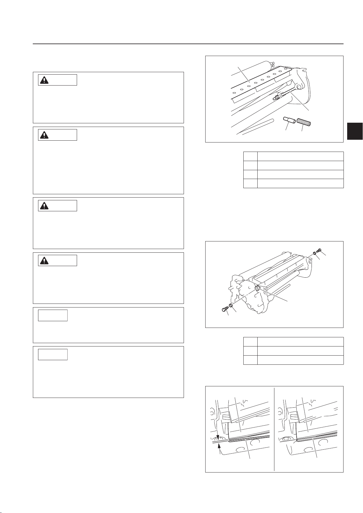
Installation of Bed Knife Base
Caution
Caution
Caution
Caution
Important
Important
3
4
2
1
kx7caa-011
3
1
1
2
2
5ttm1g-009
11
2
2
AB
kx7caa-005
Both the reel cutter (cutting cylinder) and the
bed knife (bottom blade) are edged tools.
Handle them carefully, since they could cut
your hands and feet.
LM101
Maintenance
When handling the reel cutter (cutting
cylinder) or bed knife (bottom blade), wear
gloves to protect your hands.
Pay attention not to let the reel cutter (cutting
cylinder) catch your gloves. Otherwise, you
may injure your hand or fingers.
While operations are performed with the front
of the machine raised, there is a danger of it
falling.
Securely support the machine.
Refer to the Tightening Torque table.
Note that the Baroness product warranty may
not apply to defects caused by incorrect or
overtorque tightening, etc.
Installation of Bed Knife Base_001
Collar
1
2 Compression spring
3 Cutter adjustment bolt
4 Bed knife base COMP
Temporarily install the left and right cutter
2.
pins.
Note:
At this time, tighten the lock nuts to the
heads of the cutter pins, but do not allow
the lock nuts to contact the cam bushes.
Maintenance
Make sure that there is no binding at the cam
bushes in the frame of the mower unit.
Install the bed knife base COMP parallel to
the mower unit.
During installation, be careful not to twist both
arms.
Remove the collar and compression spring
1.
from each (left and right) adjustment bolt,
and then temporarily install the bed knife
Maintenance (Mower)
base COMP onto the mower unit.
Installation of Bed Knife Base_002
Lock nut
1
2 Cutter pin
3 Cam bush
Make sure that the bed knife (bottom blade)
3.
contacts the reel cutter (cutting cylinder).
Installation of Bed Knife Base_003
Page 5-19

1
2
kx7caa-006
1
kx7caa-004
1
kx7caa-012
3
2
1
kx7caa-013
2
1
3
2
3
4
4
kx7caa-014
LM101
Maintenance
1 Reel cutter (cutting cylinder)
2 Bed knife (bottom blade)
3 Gap
4 No gap
Insert one or two strips of newspaper into
4.
the space between the reel cutter (cutting
cylinder) and the bed knife (bottom blade)
at an angle of 90 degrees. Then, rotate the
reel cutter (cutting cylinder)
counterclockwise (as seen from the left side
of the mower unit) by hand to check the
sharpness of the entire range (three or four
points from the left edge to the right one) of
the reel cutter (cutting cylinder).
Adjust the positions of the cam bushes so
6.
that both sides cut.
Installation of Bed Knife Base_006
Cam bush
1
Use a marker, etc., to place a mark on the
7.
mower unit frame at the position of the
punch mark on the cam bush, and then
remove the cutter pin.
Installation of Bed Knife Base_004
Reel cutter (cutting cylinder)
1
2 Bed knife (bottom blade)
Align the punch mark on each (left and
5.
right) cam bush with the travel direction.
Installation of Bed Knife Base_005
Punch mark
1
Installation of Bed Knife Base_007
Cam bush
1
2 Lock nut
3 Cutter pin
Remove the bed knife base COMP from the
8.
mower unit, and then install the collars and
compression springs onto the left and right
adjustment bolts.
Page 5-20
Installation of Bed Knife Base_008
Maintenance (Mower)

1 Bed knife base COMP
2
3
1
kx7caa-015
Important
3
1
1
2
2
5ttm1g-009
1
2
2
5ttm1g-008
1
1
2
kx7caa-016
Caution
Caution
2 Collar
3 Compression spring
4 Cutter adjustment bolt
Install the bed knife base COMP onto the
9.
mower unit.
Install the left and right cutter adjustment
10.
nuts, and then evenly tighten them until the
positions of the bed knife base and cam
bush are aligned.
Maintenance
12.
Install the rear roller Assy, and then adjust
its height.
Installation of Bed Knife Base_011
Rear roller Assy
1
2 Bolt
Install the reel cover.
13.
LM101
Maintenance
Installation of Bed Knife Base_009
Cutter adjustment nut
1
2 Cam bush
3 Bed knife base
Make sure that the cam bush does not move
from the marked position.
Install the left and right cutter pins, and then
11.
tighten the lock nuts.
Installation of Bed Knife Base_012
Bolt
1
2 Reel cover
Removing/Installing The Bed Knife
Removing The Bed Knife
Both the reel cutter (cutting cylinder) and the
bed knife (bottom blade) are edged tools.
Handle them carefully, since they could cut
your hands and feet.
Installation of Bed Knife Base_010
1
2 Cutter pin
3 Cam bush
Maintenance (Mower)
Lock nut
Raising the front part of the machine for
servicing operation may create a falling
hazard.
Support the machine securely.
Remove the bed knife base COMP.
1.
Place the bed knife base COMP on a stable
2.
workbench.
Page 5-21

2
3
1
mbl5jl-002
Caution
Caution
Caution
Important
Important
2
3
1
4miqko-003
12
4miqko-002
LM101
Maintenance
Remove the bed knife by loosening the
3. Tighten the screws uniformly with a
screw with a hammer driver or punch.
1.
hammer driver.
Removing The Bed Knife_001
Bed knife base
1
2 Bed knife
3 Screw
Installing The Bed Knife
Both the reel cutter (cutting cylinder) and the
bed knife (bottom blade) are edged tools.
Handle them carefully, since they could cut
your hands and feet.
Raising the front part of the machine for
servicing operation may create a falling
hazard.
Support the machine securely.
See the list in Tightening torques.
Note that the Baroness product warranty may
not apply to defects caused by incorrect or
overtorque tightening etc.
Installing The Bed Knife_001
Bed knife base
1
2 Bed knife
3 Screw
Note:
First, tighten the screw at the center. Then,
follow the numerical order, first to the right
and then to the left, as shown below.
Installing The Bed Knife_002
Bed knife
1
2 Screw
Page 5-22
Be sure not to scratch the bed knife base
surface where the bed knife shall be mounted.
Remove rust and dust.
Replace the old screws with new ones.
Maintenance (Mower)

Danger
Danger
Danger
Danger
1
nfzln9-023
Danger
Danger
12
A
wdzf6u-001
1
3
2
wdzf6u-002
LM101
Maintenance
Maintenance (Main Body)
Adjustment of Brake
If the brake wire is cut, the machine will be
unable to stop. This would be extremely
dangerous.
If the brake wire is cracked or damaged,
replace it with a new one immediately.
If the brake is not sufficiently effective when it
has been applied, adjust the brake wire.
Adjust the brake by use of the brake wire
1.
adjusting nut.
Adjustment of Engine Clutch
When reinstalling the engine:
Adjust the clearance between the engine
clutch and clutch facing so that it will be
approx. 0.5 - 1.0 mm (0.020 - 0.039 in) when
gripping the main clutch lever.
Adjustment of Engine Clutch_001
Engine clutch
1
2 Clutch facing
A 0.5 - 1.0 mm (0.020 - 0.039 in)
Maintenance
Adjustment of Brake_001
Adjusting nut
1
Follow the same steps to adjust the belts on
2.
the brake on the opposite side.
It would be extremely dangerous and may
result in an unexpected accident if the left and
right brakes are not equally effective.
Make sure that the left and right brakes are
3.
equally effective.
Make sure that the brake shoe does not
4.
touch the brake drum.
Avoid the brake always being engaged.
Note:
The brake shoe may touch the brake drum if
you hear a rubbing sound or the drum feels
heavy when rotating the drum.
Loosen the 4 bolts securing the engine.
1.
Insert a thickness gauge (accessory tool)
2.
from the front and rear of the clearance,
make adjustment so that the front and rear
clearances will be the same distance, and
then retighten the bolts A.
Adjustment of Engine Clutch_002
Engine
1
2 Bolt A
3 Bolt B
Maintenance (Main Body)
Page 5-23

1
3
2
A
4
wdzf6u-003
1
3
2
A
wdzf6u-004
LM101
Maintenance
When adjusting the clutch wire:
Make adjustment so that the operation
distance of the clutch plate between gripping
and releasing the main clutch lever will be
1.0 - 2.0 mm (0.039 - 0.079 in).
Adjustment of Engine Clutch_003
Engine clutch
1
2 Clutch plate
3 Clutch facing
4 Clutch wire adjusting nut
A 1.0 - 2.0 mm (0.039 - 0.079 in)
When adjusting the clutch spring:
Make adjustment so that the total length of
the spring will be 61.0 mm (2.40 in) when the
main clutch lever set in the ON position.
Note:
The factory default setting of the spring total
length is 61.0 mm (2.40 in).
The longer the spring is set, the lighter clutch
handling is provided. The shorter, the
heavier.
Loosen the lock nut and adjust the spring
1.
total length with the spring adjustment nut.
Confirm that there is no engine clutch
2.
slipping when the main clutch lever set in
the ON position.
1 Clutch spring
2 Spring adjustment nut
3 Lock nut
A 61.0 mm (2.40 in)
Change of Air Cleaner
For details on handling the engine, please refer
to the Engine's Owner's Manual.
A contaminated air cleaner element may cause
malfunction of the engine.
To maximize the life of the engine, replace the
air cleaner element at the appropriate times.
The timing for replacing the air cleaner
1.
element is described below.
[1]
Replace the air cleaner element in
accordance with the Maintenance
Schedule.
[2]
If it is significantly contaminated, replace
it, even if the hours of operation do not
exceed the specified time.
Replace the air cleaner element in the same
2.
manner as cleaning the air cleaner.
"Cleaning of Air Cleaner" (Page 4-4)
Page 5-24
Adjustment of Engine Clutch_004
Maintenance (Main Body)

Replacement of Engine Oil
Warning
Caution
Important
Important
1
2
bgmiun-019
For details on handling the engine, please refer
to the Engine's Owner's Manual.
When you replace the engine oil, be sure to
drain it into a bowl and discard it in
accordance with local laws and regulations.
Be careful with hot oil, which could cause
burns if it contacts your skin.
Be sure to use engine oil that is classified as
API Service Grade SE or higher, with an SAE
Viscosity that is appropriate for the operating
environment (ambient temperature).
LM101
Maintenance
Position the machine so that the engine will
6.
be level, then check the engine oil level
without screwing the oil level gauge into the
oil filling port.
Replacement of Engine Oil_001
Oil level gauge (Oil filling port)
1
2 Drain plug
After checking the oil level with the oil level
7.
gauge, add more engine oil if it is insufficient.
Securely tighten the oil level gauge.
8.
Maintenance
Screw the oil level gauge firmly.
Replace the engine oil more frequently if the
engine oil is contaminated, and especially if
you use the machine in dusty areas or operate
the engine at high loads or in high
temperatures.
Move the machine onto a level surface, stop
1.
the engine.
Remove the drain plug while the engine oil is
2.
warm, and then drain the engine oil into a
bowl.
Replace the drain plug in the engine.
3.
Remove the oil level gauge.
4.
Through the oil filling port, supply new
5.
engine oil.
The engine oil quantity is approximately 0.56
dm3 (0.56 L).
Long-Term Storage
Before Long-Term Storage
Remove any dirt, grass, debris, or oil stains
・
completely.
Supply oil and apply grease to appropriate
・
parts.
Long-Term Storage
Page 5-25
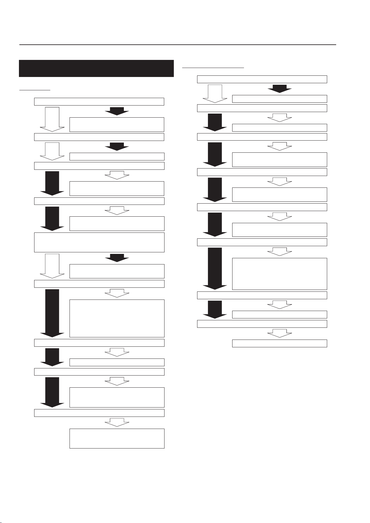
Is the roller bracket secured?
YES
NO
࣭Tightening to secure
࣭Replacement of securing screws
࣭Replacement of front roller bearing
࣭Replacement of front roller shaft
Have adjustments been made to obtain desired cutting height?
YES
YES
NO
Is there a proper balance between the bed knife (bottom
blade) and cutting height?
(
See "Cutting Height and Thickness of Bed Knife (Bottom Blade)".)
Adjustment of cutting height
Do the greens have large undulations?
࣭Change of cutting height
࣭
Replacement of bed knife (bottom blade)
NO
YES
Are the greens matted?
NO
YES
࣭Increasing of cutting height
࣭
࣭Surface finishing of greens (compaction
rolling, etc.)
࣭Increasing of cutting height
࣭
Rehabilitation of greens (vertical cutting, etc.)
࣭Application of topdressing sand
NO
YES
Are the greens sloped?
Change of cutting direction
Does the front roller rattle up and down?
NO
YES
Does the rear roller rattle up and down?
NO
YES
࣭Replacement of rear roller bearing
࣭Replacement of rear roller
YES
Is the surface of the greens finished?
࣭Increasing of cutting height
NO
If the groomer is installed: Remove the
groomer, replace the roller bracket with
the L-shaped bracket, and then bring
the front roller closer to the reel cutter
(cutting cylinder).
iuwt3m-002E
Is the cutting height on both sides adjusted to be the same?
Is the bed knife (bottom blade) chipped?
Does the front roller rattle up and down?
Adjustment of cutting height
YES
NO
NO
YES
࣭
Replacement of bed knife (bottom blade)
Does the rear roller rattle up and down?
NO
YES
࣭Replacement of front roller bearing
࣭Replacement of front roller shaft
NO
YES
Are the greens matted?
NO
YES
࣭
Replacement of rear roller bearing
࣭
Replacement of rear roller
࣭
Rehabilitation of greens
(vertical cutting, etc.)
NO
YES
Do the greens have large undulations?
NO
YES
Are the greens sloped?
Change of cutting direction
YES
Are the left frame and right frame distorted?
Contact your sales representative or dealer.
If the groomer is installed: Remove the
groomer, replace the roller bracket with
the L-shaped bracket, and then bring the
front roller closer to the reel cutter
(cutting cylinder).
7x9s4e-002E
LM101
Maintenance
Troubleshooting Procedures of Aftercut Appearance
Scalping
Angled Mismatch
Page 5-26
Scalping_001
Angled Mismatch_001
Troubleshooting Procedures of Aftercut Appearance
Overlap Marks
Do the cam bush and cutter pin rattle considerably?
Is the spring pressure for the adjustment nut too light?
NO
Adjustment of spring compression length
(See "Adjustment of Cutter Adjustment Spring".)
After loosening blade engagement, streaks still appear.
Has the bed knife (bottom blade) become curved?
NO
Is the sliding of the cam bush and frame extremely
rough?
YES
࣭Back lapping
࣭
Surface grinding of bed knife (bottom blade)
࣭
Replacement of bed knife (bottom blade)
NO
YES
Does the reel cutter (cutting cylinder) move sideways?
࣭
NO
YES
Is the reel bearing outer ring driven in at an angle?
Loosening of blade engagement
࣭Replacement of cam bush
࣭Replacement of cutter pin
࣭Replacement of cam bush
࣭Replacement of frame
࣭Correctly driving in the outer ring
࣭Replacement of reel bearing
NO
YES
Do the cam bush and frame rattle?
YES
Clean and lightly apply grease to make sliding smoother,
and then reassemble.
YES
NO
NO
NO
YES
NO
Is the reel bearing malfunctioning?
<Important>
࣭Replacement of reel bearing (Replace every year.)
YES
Checking proper tightening of bearing on reel
cutter (cutting cylinder)
(See "Attaching Reel Cutter (Cutting Cylinder)".)
Profusely apply grease to the reel bearing before installing
it. Replace the oil seal at the same time.
<Important>
For replacing the frames, contact your
sales representative or dealer.
or58dr-003E
LM101
Maintenance
Maintenance
Troubleshooting Procedures of Aftercut Appearance
Overlap Marks_001
Page 5-27

Is the spring pressure for the adjustment
lever too light?
࣭Replacement of cam bush
࣭Replacement of cutter pin
Is the sliding of the cam bush
and frame extremely rough?
Clean and lightly apply grease
to make sliding smoother, and
then reassemble.
Are genuine parts used for the blades?
Is the blade face of the bed knife (bottom blade) too rough?
Has topdressing sand been applied?
࣭Stopping use of groomer
࣭Increasing groomer height
Work in sand
Adjustment of spring compression length (See "Adjustment of Cutter
Adjustment Spring".)
Is the blade contact uneven?
Do the cam bush and frame rattle?
Do the cam bush and cutter pin rattle considerably?
Is the reel bearing malfunctioning?
Is the blade engagement tight?
Replacement of blades with genuine parts
Loosening of blade engagement
Is the groomer being used?
After loosening blade engagement, blades still
do not cut.
Has topdressing sand recently
been applied to the greens?
Use lapping powder with a grit
size of #200 – #400.
Work in sand
Is there runout or bending in the
reel cutter (cutting cylinder) shaft?
Is the frame warped near the
mounting location of the reel
bearing?
࣭
Correctly driving in the outer ring
࣭
Replacement of reel bearing
<Important>
Profusely apply grease to the reel bearing before installing
it. Replace the oil seal at the same time.
࣭Replacement of reel bearing (Replace every year.)
࣭Cylindrical grinding of reel
cutter (cutting cylinder)
࣭Replacement of reel cutter
(cutting cylinder)
Is the reel bearing outer ring
driven in at an angle?
YES
YES
NO
NO
NO
YES
YES
YES
YES
NO
YES
YES
NO
YES
YES
YES
NO
NO
YES
YES
YES
YES
YES
YES
YES
Is the grit size of the lapping
powder #200 – #400?
<Important>
For replacing the frames, contact your
sales representative or dealer.
࣭Replacement of cam bush
࣭Replacement of frame
NO
NO
NO
<Important>
For replacing the frames, contact
your sales representative or dealer.
࣭Replacement of frame
t3iz9v-002E
LM101
Maintenance
Blade does not cut.
Page 5-28
Blade does not cut._001
Troubleshooting Procedures of Aftercut Appearance

Uneven Blade Engagement
Important
Important
The unevenness is a difference of tightening
torque between the left and right cutter
adjustment nuts, or blade engagement on only
one side, which cannot be adjusted.
Promptly resolve the issue in order to maintain
the optimum performance of the machine.
Cause of unevenness Measure to resolve
Cylindrical grinding of
Asymmetrical wear of
reel cutter (cutting
cylinder)
Asymmetrical wear of
bed knife (bottom blade)
Distortion of frames
reel cutter (cutting
cylinder)
Replacement of reel
cutter (cutting cylinder)
Surface grinding of bed
knife (bottom blade)
Replacement of bed
knife (bottom blade)
Rearrange frames in
parallel
LM101
Maintenance
Maintenance
Depending on the extent of the symptoms,
they may not be resolved.
Performing temporary measures may cause
the symptoms to progress, resulting in cutting
issues.
Temporary measures:
Adjustment with cam bushes
・
"Adjusting CAM" (Page 5-11)
Adjustment of spring pressure
・
"Adjustment of Cutter Adjustment Spring"
(Page 5-10)
Troubleshooting Procedures of Aftercut Appearance
Page 5-29

LM101
Maintenance
Page 5-30
Troubleshooting Procedures of Aftercut Appearance

Head Office
1-26, Miyuki-cho, Toyokawa,
Aichi-Pref. 442-8530 Japan.
Tel : (0533) 84 - 1390
Fax : (0533) 89 - 3623
LM101---UM--USZ/18B-00-S.K
 Loading...