


Hammer Knife Mower
Serial No.10101-
Owner's operating manual
Read this manual and the owner's manual for the engine before using the machine.Required reading
Original lnstructions Ver.1.2

DANGER
WARNING
WARNING
CAUTION
CAUTION
CAUTION
CAUTION
CAUTION
CAUTION
DANGER
CAUTION
CAUTION
CAUTION
CAUTION
CAUTION
CAUTION
CAUTION
CAUTION
Warning for Safety
Purpose
Safe Operating Practices
Location of labels
1. Precautions as to use
2. Safety operation
3. Part names
4. Features
5. Specifications
6. Inspection before use
6-1. Lubrication to each part
6-2. Inspection of hydraulic oil
6-3. Hydraulic oil change
6-4. Battery
WARNING
6-5. Lubrication of friction surface of each part
7. Tightening each part
8. Engine starting sequence
8-1. Engine start
WARNING
8-2. Engine start . operation method
8-3. Engine stop method
CAUTION
8-4. Precautions to take when leaving the machine
9. Machine operation
CAUTION
9-1. Machine operation
CAUTION
9-2. Knife clutch
WARNING
9-3. Traveling lever
9-4. Mowing height adjustment
9-5. Working speed
9-6. Step (simple riding unit)
CAUTION
9-7. Traveling on the public roads and the limit of crew
9-8. Alarm buzzer
9-9. Side brake
10. Mower unit
10-1. Use of both sides of knife
10-2. Replacement of knife
10-3. Grinding the knife
10-4. Standard time for knife replacement
10-5. Hammer Knife inspection items
10-6. As for the protection cover
11. Operation on slope
11-1. Operation on slope
10
10
11
11
11
11
12
13
14
14
14
14
14
14
15
15
15
15
15
16
16
17
17
17
17
17
17
17
18
18
18
19
19
1
WARNING
2
2
5
7
8
9
CAUTION
CAUTION
CAUTION
CAUTION
CAUTION
CAUTION
11-2. Precautions as to Operation on a steep slope
CAUTION
CAUTION
12. Precautions as to maintenance
12-1. Precautions as to maintenance
WARNING
12-2. Prevention of damage due to high-pressure oil
DANGER
12-3. Precautions as to fuel handling
DANGER
12-4. Precautions as to battery handling
13. Maintenance schedule
14. Belt adjustment
14-1. Knife
14-2. Hydraulic pump
14-3. List of the place using belts
15. Crawler
15-1. Crawler tension
.
15-2. Installation
removal of crawler
15-3. Prevention of crawler tearing loose
15-4. Greasing the crawler
CAUTION
16. Adjustment of traveling section
CAUTION
16-1. Adjustment of neutral position of piston pump
16-2. Adjustment of neutral position of traveling lever
16-3. Confirmation after adjustment
17. Engine
Precautions as to handling of engine
18. Hoisting and jacking up the machine
CAUTION
18-1. Hoisting
18-2. Jacking up
CAUTION
19. Attaching/detaching the mower unit
19-1. Removal of mower unit
19-2. Installation of the mower unit
19-3. Hydraulic cylinder single-/double-acting changeover
20. Gear oil change for traveling motor
21. Wiring diagram
22. Hydraulic circuit
22-1. Valve module detail
23. Troubleshooting
23-1. Engine trouble
23-2. Traveling system trouble
23-3. Mower unit trouble
23-4. Overheating
23-5. Step trouble
24. Checklist
19
20
20
20
20
20
21
21
21
21
22
23
23
23
23
23
23
24
24
25
25
25
25
25
26
26
26
27
27
27
28
29
30
31
31
33
34
36
36
37

Warning for Safety
50h
Warning labels with the mark have been attached to this machine. The labels indicate
the items which are particularly important from the safety point of view, so please work
safety and always obey warnings.
Warning Marks
DANGER
Negligence of the warning will cause death or
serious injury.
Greeting
Thank you very much for purchasing the BARONESS HAMMER KNIFE MOWER
HMC156E/HMC172E.
This handling manual explains the method of correct use, adjustment and inspection
of the HAMMER KNIFE MOWER. Carefully read this manual before operation so as to
thoroughly understand the machine. The machine is shipped after sufficient trial operation
and inspection when it is completed at the factory. However, whether or not the machine
can exhibit its expected performance depends greatly on the handling method, as well
as the skill of inspection, adjustment, and lubrication before and after operation. Carefully
maintain your machine to bring out the best in the machine and for safe operation. Keep
this manual near the machine for future reference to confirm unclear points as necessary.
WARNING
CAUTION
CAUTION
Symbols
Negligence of the warning may cause death or
serious injury.
Negligence of the warning may cause injury and /
or physical damage.
In case of negligence of the instruction, machine
damage may be anticipated.
See the Handling Manual
Caution mark
(Rotating parts)
Caution mark
(Hot surface)
Fuel mark
(Light oil No.2)
Caution mark
(Exhaust gas)
Danger mark
(Flying objects)
Danger mark
(Blade rotation)
Grease
Every 50hours
Warning mark
(High-pressure oil)
Danger mark
(Strict prohibition of fire)
= CAUTION =
The type of the machine may change sequentially. Please inform us of the machine No.
when making an inquiry.
For improvement the contents of this manual are subject to change without notice.
CAUTION
Warning marks have been used in this Manual and machine to ensure that you can
operate it safely. Please read carefully to understand well.
Thoroughly understand the operation procedure and safety cautions before you operate
this machine.
The marks and accompanying explanations should be preserved in their entirety. If they
become lost or damaged please replace them immediately with new ones.
Caution mark
(Crushing)
Warning mark
(Clothes for safety)
-1-

-2-
Purpose
This machine is intended for cutting grass. Do not use this machine in any way other
than its intended purpose, and do not modify the machine. Operating this machine for
other purposes and modifying it may be very dangerous and may cause damage to the
machine.
This machine is not authorized for operation as a special motor vehicle. Do not operate
it on public roads.
Safe Operating Practices
The following instructions include the ones from the CEN standard EN 836:1997, ISO
standard 5395:1990, and ANSI B71.4-2004.
1. Training
Read the Owner's operating Manual and other training material carefully. Be familiar
with the controls, safety signs, and the proper use of the equipment.
If the operator or mechanic can not read English it is the owner’s responsibility to
explain this material to them.
All operators and mechanics should seek and obtain professional and practical
instruction. The owner is responsible for training the users. Such instruction should
emphasize:
the need for care and concentration when working with ride-on machines;
control of a ride-on machine sliding on a slope will not be regained by the
application of the brake. The main reasons for loss of control are:
Insufcient crawler(s) grip;
Being driven too fast;
Inadequate braking;
The type of machine is unsuitable for its task;
Lack of awareness of the effect of ground conditions, especially slopes;
Incorrect hitching and load distribution.
Never allow children or people unfamiliar with these instructions to use or service the
machine. Local regulations may restrict the age of the operator.
The owner/user can prevent and is responsible for accidents or injuries occurring to
themselves ,other people, or property.
Keep in mind that the owner, operator, and mechanic are responsible for accidents or
hazards occurring to other people or their property.
2. Preparation
Evaluate the terrain to determine what accessories and attachments are needed to
properly and safely perform the job. Only use accessories and attachments approved
by the manufacturer.
While operating, always wear substantial footwear, long trousers, hard hat, safety
glasses,mask, and ear protection. Long hair, loose clothing, or jewelry may get
tangled in moving parts. Do not operate the equipment when barefoot or wearing
open sandals.
Inspect the area where the equipment is to be used and remove all objects such as
rocks, toys and wire which can be thrown by the machine.
• Warning - Fuel is highly ammable. Take the following precautions:
Store fuel in containers specically designed for this purpose.
Add fuel before starting the engine. Never remove the cap of the fuel tank or add fuel
while the engine is running or when the engine is hot.
Refuel outdoors only and do not smoke while refueling.
If fuel is spilled, do not attempt to start the engine but move the machine away from
the area of spillage and avoid creating any source of ignition until petrol vapours have
dissipated;
Replace all fuel tanks and container caps securely.
Check that operator’s presence controls, safety switches and shields are attached
and functioning properly. Do not operate unless they are functioning properly.
If the brake operation is faulty or the parking brake lever has noticeable play, be sure
to adjust or repair them before operating the machine.
Replace faulty mufers.
Before using, always visually inspect to see that the blades, blade bolts, and cutting
assembly are not worn or damaged. Replace worn or damaged blades and bolts in
sets to preserve balance.

3. Operation
Do note operate the engine in a conned space where dangerous carbon monoxide
fumes can collect.
Only operate in good light, keeping away from holes and hidden hazards.
Before attempting to start the engine, disengage all blade attachment clutches, shift
into neutral, and engage the parking brake.
Only start engine from the operator’s position.
Avoid operating the equipment in wet grass, where feasible.
Remember there is no such thing as a safe slope. Travel on grass slopes requires
particular care.
To guard against overturning.
Do not stop or start suddenly when going up or downhill.
Machine speeds should be kept low on slopes and during turns.
Stay alert for humps and hollows and other hidden hazards.
Never operate across the face of the slope, unless the machine is designed for this
purpose.
Never drive the machine on a slope with an angle of gradient that is greater than that
specied or in a place where there is a danger of the machine slipping.
Never operate the machine with damaged guards, shields, or without safety protective
devices in place.
Be sure all interlocks are attached, adjusted properly, and functioning properly.
Never operate with the discharge deector raised, removed or altered.
Do not change the engine governor settings or overspeed the engine. Operating the
engine at excessive speed may increase the hazard of personal injury.
Do the following before leaving the operator’s position:
stop on level ground;
disengage the power take-off and lower the attachments;
change into neutral and set the parking brake;
stop the engine and remove the key.
Disengage the drive to attachments, stop the engine, and remove the ignition key in
the following conditions:
before refuelling;
befo re making h eight adjustme nt unless adj ustment can be mad e f rom the
operator's position:
before clearing blockages;
before checking, cleaning or working on the machine.
whenever you leave the machine;
after striking a foreign object or if an abnormal vibration occurs.
Inspect the machine for damage and make repairs before restarting and operating the
equipment;
Keep hands and feet away from the cutting units and the rotating parts.
Look behind and down before backing up to be sure of a clear path.
Do not carry passengers.
Never operate while people, especially children, or pets are nearby.
Slow down and use caution when making turns and crossing roads and sidewalks.
Stop the blades rotating before crossing surfaces other than grass.
Disengage drive to attachments when transporting or not in use.
When using any attachments, never direct discharge of material toward bystanders
nor allow anyone near the machine while in operation.
Do not operate the machine under the inuence of alcohol or drugs.
Take care when loading or unloading the machine into a trailer or a truck. Load or
unload the machine in a flat and safe place. Before loading or unloading, set the
parking brake on the truck or trailer, stop the engine, and chock the wheels.
When transporting the machine on a truck or a trailer, set the parking brake, stop the
engine, and fasten the machine to the truck with a rope or other suitable restraining
device that has sufcient strength.
When using a running board, select one with sufcient strength, length, and width and
that will not cause the machine to slip.
Close the fuel valve before transporting the machine.
Use care when approaching blind corners, shrubs,trees, or other objects that may
obscure vision.
Do not take your eyes off the road ahead. Do not operate the machine with no hands.
Reduce the throttle setting during engine run-out and, if the engine is provided with a
shut-off valve, turn the fuel off at the conclusion of operation.
-3-

-4-
4. Maintenance and Storage
Disengage drives on level ground, lower the atattachments, set parking brake, stop
engine and remove key from ignition. Wait for all movement to stop before adjusting,
cleaning or repairing.
When machine is to be parked, stored, or left unattended, lower the cutting units
unless a positive mechanical lock is provided.
To reduce the fire hazard, keep the engine, silencer/muffler, battery compartment
fuel storage area, cutting units and drives free of grass, leaves, or excessive grease.
Clean up oil or fuel spillage.
Allow the engine to cool before storing in any enclosure.
Only cover the machine with a sheet after hot parts have sufciently cooled down.
Never store the equipment with fuel in the tank inside a building where fumes may
reach an open ame or spark.
If the engine is provided with a shut-off valve,shut off valve while storing or
transporting.
Do not store fuel near ames.
Never allow untrained personnel to service machine.
Appropriately manage and correctly use the tools necessary for servicing or adjusting
the machine.
Use jack stands to support components when required.
Carefully release pressure from components with stored energy.
Be sure to depressurize the hydraulic system before performing maintenance
operations on it such as removing hydraulic equipment.
Check whether line connectors in the hydraulic system are properly tightened. Before
applying hydraulic pressure, check the connections of the hydraulic pressure lines
and the condition of the hoses.
When checking the hydraulic circuit for pinhole leaks or oil leakage from nozzles, do
not use your hands. Use items such as paper or corrugated cardboard to nd leakage
points. Be extremely careful with high-pressure oil as it may pierce your skin, resul.
If uid is injected into the skin it must be surgically removed within a few hours by a
doctor familiar with this form of injury or gangrene may result.
Disconnect battery before making any repairs. Disconnect the negative terminal rst
and the positive last. Reconnect positive rst and negative last.
Make sure that parts such as wires are not touching each other and that their covers
have not come off.
Use care when checking the blades. Wrap the blades or wear gloves, and use caution
when servicing them. Only replace blades. Never straighten or weld them.
Keep hands and feet away from moving parts. If possible, do not make adjustments
with the engine running.
Charge batteries in an open well ventilated area, away from spark and ames. Unplug
charger before connecting or disconnecting from battery. Wear protective clothing and
use insulated tools.
Keep all parts in good working condition and all hardware tightened. Replace all worn
or damaged decals.
Keep all nuts, bolts and screws tight to be sure the equipment is in safe working
condition.
If the fuel tank has to be drained, do this outdoors.

15
11
12
13
18
16
17
14
19
20
2
1
3
4
5
6
7
8
9
10
8
2
1
3
4
6
7
5
Location of labels
*Decals are indicated with ○ for warning and □ for instruction.
-5-

WARNING
WARNING
DANGER
DANGER
DANGER
DANGER
CAUTION
CAUTION
2
3
4
5
6
7
1
8
9
10
11
12
1
2
3
4
5
6
7
8
K4205001600
K4205001970
K4205001520
K4205001950
K4205001570
Decal, danger hammer knife
Pay attention to the flying object Do not allow people to approach
the front of the machine.
Hands injury - Keep a safe distance
from the machine.
Engine
oil
Hydraulic
oil
Gear oil
K4205001530
Decal, caution for rotating object
Watch for rotating parts - Keep your
hands away from the belts while the
engine is running.
K4205001600
Decal, caution for severe injury
May cut your hand or leg - Stop the
rotation and engine.
Otherwise you may get injured.
K4205001970
Decal, caution spouting coolant
Pay attention to the radiator - Do not
open the cap of radiator when it is in
the hightemperature.
High temperature - Do not touch, or
you will get burnt.
K4205001520
Decal, prohibition rope installation
Do not use the step to tow or rope.
K4205001950
Decal, caution exhaust gas
Pay attention to the exhaust gas Keep a safe distance from the
machine.
K4205001560
Decal, read Owner's manual
Instruction - Read the Owner's
Operating Manual before operating
or servicing the machine.
K4205001550
Decal, caution fire
Pay attention to fire - Read the
Owner's Operating Manual.
K4205001540
Decal, caution for high temperature
High temperature - Do not touch.
Otherwise, you will be burned.
K4209001090
Decal, oil handling instruction
Read the Owner's Operating
Manual about the designated oils.
K4209001110
Decal, slope work instruction
Operation on the slope - Read the
Owner's Operating Manual.
K4209001040
Decal, instruction of hoisting
Hoisting the machine - Read the
Owner's Operating Manual.
K4209001000
Fuel icon
Use No. 2 diesel fuel. (Low sulfur
or ultra-low sulfur diesel fuel only)
K4209001050
Decal, emergency engine stop
Loop the cord of emergency switch
around the arm or body tightly.
K4209000990
Decal, pilot lamp
K4209001030
Decal, overheat alarm buzzer
When overheated - Read the
Owner's Operating Manual.
K4203001200
Decal, traveling lever
K4203001210
Decal, P-brake
K4203001230
Decal, knife clutch lever
K4204000080
Decal, mowing height scale
When the cutting height set less
than 3cm or over 30cm, disengage
the knife clutch.
Unlock
Forward
High speed
Lock
Off
Backward
High speed
Low speed
Neutral
Low speed
On
5
10
15
20
25
30
cm
3
Glow
lamp
Oil pressure
lamp
Charge
lamp
Blade rotation
prohibition range
Blade rotation
prohibition range
Left-hand
Turning
Right-hand
Turning
Warning and Instruction Decal List
*Decals are indicated with ○ for warning and □ for instruction.
-6-

1
1
2
3
2
3
1
2
50h
K4209000380
Maintenance
Ordinary operation
Auto
Manual
High speed
Engine stop
(Auto glow)
On
High Low Low High
Start
K4209001060
Decal, step control changeover
switch
When cutting grass, switch to the
AUTO mode.
K4209001070
Decal, manual step control
Use it when the step control is in
the MANUAL mode.
K4209001080
Decal, cylinder single/double
changeover
K4203001220
Decal, engine rotation
K4209000380
Decal, greasing 50 Hr
K4209001020
Decal, read owners manual
Read the Owner's Operating
Manual.
K4204000070
Decal, mowing height switch
K4209001430
KEY SWITCH MARK
K4209000980
Hydraulic oil icon
Read the Owner's Operating
Manual.
Low speed
Inclination
to the left
Inclination
to the right
13
14
15
16
17
18
19
20
Desired
Locations
*Decals are indicated with ○ for warning and □ for instruction.
1. Precautions as to use
1-1.
WARNING
Preparation before use of machine
Be sure to check and maintain the machine before and after use.
The protective cover and other protective parts are provided to prevent users
from danger. Be sure to install them at the specified locations, and replace them
with new ones when they are broken.
Carefully read the warning labels and operation manual before operating the
machine to thoroughly understand the machine operation.
WARNING
Emergency switch1-2.
Unless the emergency switch is used, the engine may not stop in an emergency,
leading to death or serious injury.
Be sure to install the emergency switch correctly. Wind the string of the
emergency switch around your arm or body completely before using the
machine.
1-3.
DANGER
Be careful of rotating parts
The knife and other rotating parts are dangerous. Do not put your hands, feet, or
any other object in them or do not touch them during work or maintenance.
Check that there is no person or other objects that may break the machine
around the machine or in the area within 30 degrees and 100 m at the front of
the machine during operation.
Stones, wires, sticks, and other obstacles may cause damage to the knife or an
accident due to flying objects. Remove them before operating the machine.
-7-
CAUTION
Wires, vinyl and other objects may be wound around the knife shaft. When you
hear an abnormal sound, stop the engine, and remove such objects after the
knife shaft has stopped rotation.
Should the knife be broken, the knife shaft will be unbalanced, causing vibration,
which is very dangerous. Be sure to change the knives, otherwise the machine
will be broken.
CAUTION
Be careful of hot part1-4.
Do not touch the cover or muffler during operation or right after the machine
stops, otherwise a skin burn may result.

-8-
1
2
3
1
2
3
4
5
8
6
9
7
10
2. Safety operation
Blades rotate at high speed in the mowing machine under severe conditions such
as vibration, slope, and dust. Operation conditions are subject to the place of use,
existence of obstacles, condition of grass, etc. We sincerely desire that users should
inspect and maintain the machine completely, make efforts to master the machine
operation skill, take measures for safety, use the machine correctly so as not to do
harm to others, and give top priority to safety operation.
2-1.
Wear proper clothes that will not be caught in the
machine, and wear protective gear, goggles, shoes,
helmet, and gloves.
An apron and a towel wound around the waist, as
well as long strings especially, will cause the operator
to be caught in or pulled into the machine, which is
dangerous. Provide a fire extinguisher, first aid kit and
secure a means of communication to deal with an
emergency.
2-2.
2-3.
Before operating the machine, check the field by necessity. Pay attention to the
holes or obstacles.
Remove the objects that can fly apart as possible as you can. Give attention to the
flying debris not to injure people, animals, crops, buildings, automobiles and so on.
WARNING
WARNING
Do not use the machine when you are tired. When you feel tired while using the
machine, stop the work and take a rest.
Sick people, drunken people, and people under the influence of drugs are
not allowed to use the machine. The visual sense, nimbleness in action, and
judgment will be adversely affected.
When you are unfamiliar with machine operation, read the handling method and
safety precautions to understand them well before operating the machine. Do
not allow children to use the machine.
CAUTION
Clothes for safety
Avoid such operation
Check the operating place.
CAUTION
Do not operate the machine with mown grass, dust, etc. accumulated in the
cover, V-belt or around the engine or the transmission, otherwise fire or other
trouble may result. Remove them carefully. Improper maintenance and incorrect
operation and dry grass mowing might cause fire. Clean and check the machine
as shown below before and during work.
Remove dry grass, dust, and other obstacles from around the muffler and
engine.
Check the fuel hose for cracks due to deterioration.
Check for fuel leakage during fuel supply.
Fuel supply during engine operation is prohibited.
Check the wiring to prevent fire due to a short circuit.
Inspect the fuel tank and carburetor for fuel leakage due to operation on a slope.
Be sure to carry a fire extinguisher and water etc. when mowing dry grass.
When cutting dried grasses, clean the machine every 1 hour.
In case of fire, use extinguisher to extinguish it in the early stage. When the fire
expanded, evacuate to the safety place and report to the fire department.
Make sure of the expiry date of extinguisher at any time.
2-5.
The machine is not provided with any lighting equipment. Do not operate the
machine at nighttime or when the visibility is poor due to bad weather, etc.
Do not remodel the machine. Use genuine parts for maintenance to ensure safety.
Never use the machine for tree felling and wood chipping, tilling the farmland, or
some works other than mowing, otherwise the machine may lose its knife shaft
balance and cause failure.
WARNING
CAUTION
CAUTION
Prohibition of nighttime traveling and work
Remodeling of the machine prohibited2-6.
Prohibition of work other than mowing2-7.
Fire prevention2-4.

2-8.
35
20
67
18
24
8
16
15
14
13
21
12
11
22 23
17
9
10
4
19
21
When lending the machine to others, an unexpected accident may occur because
they have no knowledge about the safety precautions and handling method shown
in the operation manual. Hand over the operation manual and tell them to read it
carefully before using the machine, explaining the handling method well.
CAUTION
When lending the machine to others
Protection cover and Antiscattering chain
The protection cover is used to prevent stones, etc. from scattering foward. Be sure
to lower the protection cover during mowing operation.
The antiscattering chain is also used to prevent stones, etc. from scattering forward.
Be sure to install the chain to prevent damage to human beings, buildings, vehicles,
etc.
However, due to the structure of the machine, the protection cover and the
antiscattering chain can not prevent all the objects from scattering. Even when
installing these equipments, always exercise due care for surrounding area
(especially for forward) during operation.
3. Part names
CAUTION
Observe the precautions in "Precautions as to use" and "Safety operation" and pay
sufficient attention to the area around the machine during operation.
No. Name No. Name
1 Handle 13 Bottom roller
2 Side brake lever 14 Front roller
3 Throttle lever 15 Knife guard
4 Traveling lever 16 Muffler
5 Knife clutch lever 17 Fire extinguisher
-9-
6 Mower portion (Mower unit) 18 Precleaner
7 Protection plate 19 Main switch
8 Protection cover 20 Battery
9 Emergency switch 21 Fuel ller port (diesel fuel)
10 Step 22 Step control changeover switch
11 Sprocket 23
12 Crawler 24 Air cleaner
Cylinder single-/double- acting changeover switch

-10-
4. Features
This energy-saving type large mowing machine with a diesel engine is
manufactured for professional use especially for slope land operation. The mowing
width is 154 or 170 cm, and the maximum output is 26.5 kW. The machine is ideal
for mowing on river banks, skiing ground and major roads, as well as in other large
areas.
The rubber crawler ensure great hill climbing ability, and the low center of gravity
permits safe work even on a slope. The crawler section is provided with a seesaw
roller mechanism to cope with pitching, and the projections inside the crawler
are made long to prevent crawlers from coming off. The grease cylinder used for
crawler tension adjustment is easy to operate.
The machine travels hydraulically at variable speed. The single traveling lever
permits simple operation to move the machine forward and backward, change the
speed, and turn the machine. The position of the traveling lever can be selected
from five angles, ensuring satisfactory operation and improvement of work
efficiency.
The hydraulic system permits easy adjustment of mowing height. The special
structure of the mower unit permits long grass cutting length and easy collection of
cut grass. The grass stop shaft (option) makes the cutting length shorter.
The step (simple riding unit) keeps the machine horizontal by using an angle
sensor so as to enhance safety of the operator.
The hammer knives are attached to move freely and the structer lessens impact
of stones and other obstacles when they hit against the hammer knives, hardly
causing damage to the hammer knives.
The hammer knife is made of heat-treated special touch steel, ensuring sharp
cutting and durability and permitting use of both sides by reversing. The hammer
knives are attached by bolts and nuts, permitting easy change.
The four-cylinder diesel engine with a starter is easy to start, and the forced
lubrication system can withstand the instantaneous maximum inclination of 35
degrees.
The hitch method is adopted to install the mower unit, permitting easy installation/
removal of the portion.
5. Specifications
HMC156E HMC172E
Total length
Dimensions
Total width
Total height
1,717mm 1,910mm
Mitsubishi Diesel S4L2-E331KM 1.758L (1,758 cm3)
Engine
Rubber crawler
Speed change
(Hydraulic variable speed)
Hammer knife
Knife clutch
Mowing height
Mowing width
Max. output: 27.0 kW/3,000 rpm (36.7 PS/3,000 rpm)
30 7.2cm(51P)
Backward: 0-4.5 km/h
120 blades 140 blades
154cm 170cm
70 are/h (6.5 km/h) 77 are/h (6.5 km/h)
Efficiency
(Mowing width Operation speed 0.7)
Max. operating inclination
Ground pressure
Dry weight
Curb weight
The factory default maximum engine rpm is 2,400 rpm.
*
CAUTION
The idling speed of the engine is approx. 1,500 rpm. Set the idling speed to avoid
sympathetic vibration with the machine. The engine revolution may reach 3,200 rpm
under no-load condition.
16.7kPa
1,480kg
1,545kg
3,000mm
1,350mm
Fuel tank: 33 L (dm3)
35 7.2cm(51P)
Forward: 0-6.5 km/h
Belt tension type
3-30 cm
35
14.7kPa
1,520kg
1,585kg

CAUTION
1
2
3
1
2
3
4
For transportation of the machine, give attention to the width of the loading space.
HMC156E
Vibration Level
Hand-arm vibration
This machine was confirmed to transmit a maximum vibration level of 4.50 m/
s2 to hands and arms by measuring identical machines in accordance with the
procedure specied in ISO5349-1: 2001, 5349-2: 2001.
Sound Pressure Level
This machine was confirmed to have a continuous A-weighted sound pressure
level of 90 dB by measuring identical machines in accordance with the procedure
specified in directive EN836:1997.
Sound Power Level
This machine was conrmed to have a sound power level of 105 dB by measuring
identical machines in accordance with the procedure specied in directive 2000/14/
EC.
Vibration Level
Hand-arm vibration
This machine was confirmed to transmit a maximum vibration level of 4.50 m/
s2 to hands and arms by measuring identical machines in accordance with the
procedure specied in ISO5349-1: 2001, 5349-2: 2001.
Whole body vibration
This machine was conrmed to transmit a maximum vibration level of 1.30 m/s2 to
the whole body by measuring identical machines in accordance with the procedure
specied in ISO2631-1: 1997, 2631-2: 2003.
HMC172E
Sound Pressure Level
This machine was confirmed to have a continuous A-weighted sound pressure
level of 90 dB by measuring identical machines in accordance with the procedure
specied in directive EN836:1997.
Sound Power Level
This machine was conrmed to have a sound power level of 105 dB by measuring
identical machines in accordance with the procedure specied in directive 2000/14/
EC.
Whole body vibration
This machine was conrmed to transmit a maximum vibration level of 1.30 m/s2 to
the whole body by measuring identical machines in accordance with the procedure
specied in ISO2631-1: 1997, 2631-2: 2003.
6. Inspection before use
Inspect the machine according to "13. Maintenance schedule."
6-1. Lubrication to each part
Supply the specified quantity.
Don't use old oil.
Lubrication the friction surfaces of each part.
Refer to the diesel engine operation manual for the method of handling the
engine.
6-2. Inspection of hydraulic oil
Approx. 28 litters of hydraulic oil is in the hydraulic tank. Place the machine
horizontally and check that the level of the hydraulic oil is at the center of the oil
gauge.
6-3. Hydraulic oil change
CAUTION
Change the hydraulic oil one year or 500 hours later, whichever comes earlier.
Change the filter when the hydraulic oil is changed.
When the hydraulic oil is emulsified or its transparency is lost even slightly,
change it instantly.
For lling up the hydraulic oil, use the designated oil.
Use Shell Tellus S3MT46 or equivalent of ISO VG46 as hydraulic oil.
CAUTION
Change the hydraulic oil, after the machine cooled down sufciently.
When servicing the hydraulic system, lower the mowing units to the ground and
release the pressure.
-11-

-12-
U PPER LEVEL
UPPER LEVEL
L OWER LEVEL
LOWER LEVEL
U PPER LEVEL
UPPER LEVEL
L OWER LEVEL
LOWER LEVEL
1
1
2
6-4. Battery
Inspection of Battery
For details on handling the battery, please refer to the separate Battery Instruction
Manual.
DANGER
Keep re away while inspecting or charging the battery.
The battery may explode.
WARNING
Do not allow the battery fluid level to become lower than the LOWER LEVEL
(minimum uid level line).
The battery may explode if it is used or charged while the battery uid level is at
the LOWER LEVEL (minimum uid level line).
Clean the areas around the battery uid level lines using a cloth dampened with
water.
Make sure that the battery uid level is between the UPPER LEVEL (maximum
uid level line) and the LOWER LEVEL (minimum uid level line).
Supply of Battery Fluid
For details on handling the battery, please refer to the separate Battery Instruction
Manual.
DANGER
Be careful not to let your skin, eyes or clothes, etc., come into contact with battery
uid (electrolyte) or accidentally swallow the uid.
Should your skin or clothes come into contact with electrolyte, immediately wash
them away with water.
WARNING
When you supply battery uid, wear protective garments and safety glasses, etc.
If the battery fluid level is lower than halfway between the UPPER LEVEL
(maximum line) and LOWER LEVEL (minimum line), add puried water up to the
UPPER LEVEL (maximum line).

6-5. Lubrication of friction surface of each part
50h
Supply oil constantly to the inlet/outlet of the wire and the joint of each part to
prevent rusting. Supply grease to the grease nipple every 50 hours.
Crawler [26 places]
Both sides of knife shaft assy. (2 places)
Fulcrum of mower unit [2 places]
The drawing shows the right side.
*
Operation lever and neutral positioning [8 places]
Tension [3 places]
-13-

-14-
3
4
2
2
1
1
Start
Stop
Position
Energization and preheating
Charge
lamp
Glow
lamp
Oil
pressure
lamp
7. Tightening each part
Bolts are used for each part. After initial use of the machine, the bolts and nuts may
get loose. Tighten loose bolts and nuts.
Optimum tightening torque: N.m (kgf.cm)
M 6
M 8
M10
M12
M14
Ordinary bolt
8 (80)
18 (180)
36 (360)
60 (600)
90 (900)
Heat-treated bolt
16 (160)
36 (360)
72 (720)
120 (1200)
8. Engine starting sequence
8-1. Engine start
WARNING
Before starting the engine, read the diesel engine operation manual to
thoroughly understand the contents.
Put on the side brake and set all driving units at the neutral position.
Check that the covers are at correct positions and that there is no one
around the machine, and confirm safety before starting the engine.
Do not start the engine in a room without an appropriate ventilator.
Check that the knife clutch lever is disengaged before starting the engine.
8-2. Engine start.operation method
Shift the throttle lever to High rotation.
Check the indicators and preheating.
Key to “ON” position (energization
and pr eh e a t i ng ) le ts pr e h ea t i n g st a r t
automatically.
Start
After the glow lamp went out (completion of
preheating), Key to “START” position makes
the engine start.
If starting the engine before the glow
*
lamp goes out, it may cause blowout of
the fuse.
Operation
Key to “ON” position.
CAUTION
Within 5 seconds after starting the engine, the safety equipments do not function
due to the control circuit. Accordingly do not operate the machine for a period of
5 seconds after starting.
8-3. Engine stop method
Return the throttle lever to the slow-speed position.
Turn OFF the switch and remove the key.
8-4.
* When storing the machine outdoors or for a long time, be sure to put the
rubber cap on.
CAUTION
Park the machine in a horizontal state, turn off the engine, and check that all
movable sections have stopped. Then put on the side brake and remove the key
before leaving the machine. Never park the machine on a slope.
Precautions to take when leaving the machine
Traveling lever
Mowing height
adjustment
switch
Forward
Backward
Mowing height
Low
High
9. Machine operation
OFF
ON
Knife clutch lever
9-1. Machine operation
9-2. Knife clutch
Pull the knife clutch to your side to engage it, and push it forward to disengage it.
The engine cannot be started when the knife clutch is engaged.
CAUTION
Check that the operating condition of each part especially the safety of the side
brake, traveling lever and mower unit before operating the machine.
Operate the machine at slow speed so that the machine can be stopped
immediately in any case.
Remove obstacles from the operation area so that you and other people around
the machine will not be injured.
Do not start or turn suddenly, or the operator may be bucked off, or the machine
may slip or turn over on the slope. It is dangerous.
CAUTION
Engage the knife clutch right before starting mowing operation. Be sure to leave
it disengaged during any operation other than mowing.
Since the knife shaft rotates by the centrifugal force, engage the clutch halfway
until the rotation is normal. Do not engage the clutch completely at a stroke.
Even if the knife clutch disengaged, the knife shaft freewheels for a while. Do not
any operations until the knife shaft stops rotating completely.
9-3.Traveling lever
The traveling lever is at the center
of the rear section of the machine.
Push it forward to move the machine
forward, and pull it back to your side
to move the machine backward.
Adjust the speed by changing the
inclination of the lever.
Turn the traveling lever to the
direction of the desired direction
of turning. Return the lever to the
original position, and the machine will move straight.
The position of the traveling lever can be selected from five angles. Change the
position of the lever according to the operating conditions.
WARNING
When driving the machine on a steep slope, the machine will not stop even if the
traveling lever is released. When driving the machine on a slope, hold the traveling
lever with one hand and the handle with the other hand so that the machine can
stop any time. Never release them during traveling.
In case of losing control of travelling, stop the engine promptly.
9-4. Mowing height adjustment
The hydraulic method, in which a solenoid valve and cylinder are used, is adopted
for mowing height adjustment. Tilt the mowing height adjusting switch on the
traveling lever to your side to raise the mowing height, and tilt it forward to lower
the mowing height. The mowing height adjusting range is 3-30 cm. The knife
rotation above the range is prohibited for safety's sake though the mower portion
itself can be raised higher for the sake of transportation or storage. Adjust the
mowing height appropriately. Adjust the mower unit lowering speed with the valve
unit, which will be seen at the back of the fuel filler port when the right side cover is
opened.
CAUTION
Even though the engine does not run, key to “ON” position and control of the
cutting height adjusting switch make the mowing unit lower. When stopping the
machine, make sure to lower the mowing unit to the ground and after stopping the
engine, make sure to remove the key.
-15-

-16-
1
2
3
Stored positionDriving position
Step
Magnet catch
Hook
Hook for
fixing step
33221
1
9-5. Working speed
The working speed is hydraulic variable within the range of 0 - 6.5 km/h for forward
operation and 0 - 4.5 km/h for backward operation. Adjust the speed appropriately
with the traveling lever according to the condition of the geography and grass.
9-6. Step (simple riding unit)
The step is kept horizontal at all times by the angle sensor, automatic level control
box and electric cylinder. The "step control changeover switch" atop the electrical
equipment box permits switching from AUTO to MANUAL, and vice versa. When
the step control changeover switch is in the "MANUAL" position, the "step control
manual switch" on the control panel permits control.
CAUTION
However, be sure to set the step control changeover switch in the "AUTO" position
during mowing. Use the manual position only when maintaining the machine,
the automatic control circuit fails, or some other emergency arises. When the
automatic circuit fails, replace the part with a new one immediately. Do not operate
the machine for mowing on the manual control step.
CAUTION
Impact to the step will impose a burden on the supporting point, causing failure.
Exercise care so as not to strike the step against any object when moving the
machine backward or turning the machine.
How to fold back the step (driving position → stored position)
*
Lift up the step ( ). Hold the pipe at the bottom of the step, when lifting. Keep
lifting the step and raise the hook for xing step ( ) and lean it to the rear direction
of the machine ( ).
Make sure the hook for fixing step and the hook of the step clutch each other
securely.
How to fold back the step (stored position → driving position)
*
Apply the reverse procedure to the above mentioned ( → → ). Avoid the step
falling down due to its own weight and make sure to hold it. Fix the hook for xing
step with the magnet catch.
Folding back the step
The step (simple riding unit) can be folded back to conserve space in the case of
storage or transport by truck etc.
CAUTION
The steel mesh is used on the standing surface of the step for antiskid purpose. Do
not touch the mesh directly for avoiding injury.
CAUTION
In the case of traveling or operating the machine without riding on the step, the
operator cannot keep the proper distance to the control devices and the operations
become unstable. Be sure to stand on the step for starting the machine.
Prohibition of traveling and/or operating the machine with the step
in the stored position.

9-7. Traveling on the public roads and the limit of crew
This machine is not allowed to travel on the public roads. Carry this machine on the
truck to move on the public roads.
CAUTION
Single operator are able to ride on this machine. No subsidiary worker is allowed to
stand on the step or the other part of the machine. Especially when the engine is
working, never let person ride on the mowing unit or crawler.
9-8. Alarm buzzer
When the alarm buzzer sounds, the engine is overheated. Stop operation, and
remove dust that is jamming in the radiator or air cleaner etc.
CAUTION
9-9. Side brake
When the machine is not to be moved, pull the side brake lever fully to your side,
and the brake will be applied to the hydraulic motor and the traveling lever will be
locked at the neutral position.
10. Mower unit
10-1. Use of both sides of knife
Both sides of the knife are sharpened. When one side is worn, remove the pair of
knives, and attach them reversely. The knife is attached to the knife shaft mounting
hitch section by 11 mounting pin 32 and the nut with disc washer, and the knife can
be removed easily.
Attach the mounting pin in the same direction as before.
* The tightening torque of the knife mounting pin is 32 - 36 N
as ordinary M10 bolts).
10-2. Replacement of knife
10-3. Grinding the knife
CAUTION
The knife shaft assy is balanced when shipped from our factory; therefore, unless
all the knifes of the same weight each are replaced at one time, or unless replaced
symmetrically on the right and left portions of the knife shaft, the weight balance
may be lost and vibration may be generated.
Since the hammer knife shaft assy are rotated at high speed, pay attention to the
weight balance when replacing the hammer knife.
CAUTION
When both sides of the knife are worn, grind each blade in a manner that the
weight of each knife will be the same as much as possible.
When the weight balance of the knife shaft assy including the knife blades is poor,
the knife shaft assy will generate vibration, breaking the machine.
.
m (almost the same
CAUTION
When checking the knife shaft assy or replacing the knives, make sure to stop the
engine and remove the key.
CAUTION
When the balance is lost, the knife shaft assy will vibrate because it is rotating at high
speed, which is very dangerous. Exercise care sufficiently.
CAUTION
Wear protective goggles and gloves when grinding the knife.
-17-

-18-
1
234
5
6
7
Protection cover
Link
Hook
10-4. Standard time for knife replacement
Operation with a worn knife not only prevents efficient operation but also leads to
loss of balance. Reverse or replace the hammer knife according to the illustration
shown below.
Replace the hammer knife immediately with a new one when it is broken or
abraded unevenly.
New knife Time to reverse Time to replace
10-5. Hammer knife inspection items
10-6. As for the protection cover
When checking the knife shaft assy, it is easy to work with raising the protection
cover.
How to raise and lower the protection cover.
For raising the protection cover, lift up the protection cover and hook up the hooks
on both sides of the protection cover with the rings on both sides of the knife frame.
After conrming the cover will not lower, get your hands off of the cover.
For lowering the protection cover, release the hooks from the rings on both sides
and lower the cover slowly.
No. Part Inspection item Correction
Knife blade
Mounting pin
Mounting hitch
Balance weight
Support shaft Uneven abrasion Repair by specialist(*2) or replacement
Bearing
knife shaft assy
*1 The tightening torque of the knife mounting pin is 32 - 36 N.m
Excessive tightening will damage the thread of the mounting pin.
*2 Special correction by balancing machine may be required.
Missing baldes Attach
Abrasion Reverse or replacement
Breakage, curvature or uneven
abrasion
Looseness Tightening(*1)
Wrong direction Attach correctly
Curved or open Correction or repair by specialist(*2)
Breakage or uneven abrasion Repair by specialist(*2) or replacement
Missing
Abrasion
No lubrication Lubricate
Unsmooth rotation Replacement
Twining of vines or cords etc. Remove
Distortion as a whole Replacement
Replacement
Repair by specialist(*2)
CAUTION
Implement operation of the protection cover after the knife shaft assy stops
completely.
When lowering the protection cover, pay attention not to pinch hands and feet.
When raising or lowering the protection cover, pay attention not to touch the
knives.
Protection cover should be kept lowering except for checking the mowing unit or
replacing the knives.

1
2
3
4
5
6
In regard to the anti-scattering chains
Protection cover
Link
Link
Hook
Chain
Shackle
Adjust the height of protection cover with the attached rings and shackles. If you
operate the machine without adjusting the height of cover, the chains are dragged
with the lowered cover and it may cause the damage of chains and cover.
Knife guard is omitted in the drawing.
*
11-2.
Be sure to observe the following matters when using the machine on a steep slope
of 20 degrees and above.
WARNING
Do not operate the machine when there is a risk of falling or slipping.
Before starting operation on a steep slope, check for holes, rocks, tree roots,
illegal throwaways, etc. Remove them, if any, and then carefully operate the
machine.
On a steep slope, operate the machine along the contour line, and turn the
machine in a place with a small angle of inclination as much as possible.
Do not operate the machine on a slope of 35 degrees and above, because the
machine is very likely to fall down sideways.
Exercise care sufficiently also when working on a slope of less than 35 degrees,
because the machine may slip down depending on the condition of the work site.
When ropes are used on a steep slope while working together with an assistant
worker, the machine may move to a very steep slope with an angle of inclination
that exceeds the allowable angle and the risk of falling down sideways will
increase, preventing safe operation. As a maker of the machine, we will prohibit
such operation.
Precautions as to operation on a steep slope
11. Operation on slope
CAUTION
The angle meter on the operation panel shows rough indication. If you feel it is
11-1. Operation on slope
When operating the machine on a slope, move the machine upward gradually from the
bottom of the slope along the contour line.
Release the traveling lever, and the lever will be set in the neutral position, stopping the
machine. For safety, stop the machine so that it will be positioned along the contour line.
When stopping the machine vertically on a slope, the machine may not be able to stop
immediately because of the inertia of the traveling machine. The machine is provided with a
hydraulic traveling system, and the step is provided with an automatic level control sensor.
When the machine is therefore turned toward the bottom of the slope, the machine will turn
smoothly because the center of gravity of the machine changes favorably, also ensuring the
operator since this way can avoid his position just below the machine during turn.
-19-
dangerous, stop the operation immediately.
CAUTION
On the border between slope and at eld, machine is rolling roughly. And so grip
the handle tightly and maintain your position.

-20-
12. Precautions as to maintenance
Be sure to provide an appropriate support so that the
CAUTION
12-1. Precautions as to maintenance
Thoroughly understand the method of required maintenance.
Do maintenance in a dry, clean place.
Before maintain the machine, stop the engine.
When starting the engine to check the movement, do not approach the movable
part.
Stop all driving parts, and operate respective control units to release the
pressure. (Lower the mowing unit to the ground)
Install all parts in a satisfactory state.
Repair or replace damaged parts immediately.
Replace worn or damaged parts.
Do not remodel the machine. Use genuine parts for maintenance to ensure
safety.
Remove dust, grease, and oil adhering to the machine.
Remove the minus (-) wiring from the battery before maintaining the electric
system.
When starting the engine, pay attention to the exhaust gas.
machine will be secured completely when the machine is to
be lifted during operation.
12-3.
DANGER
(JIS No.2 diesel oil)
Precautions as to fuel handling
Use of fire is prohibited strictly during fuel supply.
Put out all open fire and cigarettes.
Stop the engine to cool it outdoors before supplying fuel.
To prevent fire, keep the machine clean without dust, grease, or oil at all times.
Wipe off spilt fuel cleanly.
12-4. Precautions as to battery handling
Refer to the battery instruction manual for the method of handling the battery.
DANGER
Use of fire is prohibited strictly when checking or charging the battery. The
electrolyte is dilute sulfuric acid. Do not allow it to contact your body or the
machine. If the electrolyte adheres to your body or the machine, wash it off with
water immediately. Especially when it enters your eyes or you swallow it by
mistake, see a doctor immediately.
When removing the cable from the battery, remove the negative side first, and
when attaching the cable to the battery, attach the positive side first. When the
sequence is reversed, tools may touch the machine and cause a short circuit,
generating sparks. Connect the battery cables correctly to the positive and
negative sides. If the direction of connection is wrong, the battery and its electric
equipment will be damaged.
12-2.
WARNING
The high-pressure oil, when sprayed over the skin, will cause serious injury.
Release the pressure before removing the high-pressure line, hose, and joints.
Check the tightness of all joints before starting operation.
Use a small piece of cardboard to check for leakage. When your skin is sprayed
with high-pressure oil, you must see a doctor within two to three hours.
Prevention of damage due to high-pressure oil

13. Maintenance schedule
Knife adjusting rod
Lever adjuster
Tension pulley adjusting bolt
Knife shaft V-pulley
B3 V-pulley
B6 V-pulleyEngine pulley
CAUTION
Use the appropriate tools for the purpose of maintenance etc.
Refer to the diesel engine operation manual for the method of handling the engine.
Inspection, adjustment, replenishment and cleaning
Replacement
Maintenance
Engine oil
Oil filter
Engine
Fuel filter
Electromagnetic pump filter
Air cleaner element
Precleaner
Cooling water (qty, leakage, etc.)
Fuel (qty, leakage, etc.)
Hydraulic oil (qty, leakage, etc.)
Hydraulic oil filter
Tightening of hydraulic hose/joint
Hydraulic
motor oil
Electrolyte
Radiator core
Main unit
Side brake
Traveling lever
Neutral position
Emergency switch operation
Step operation
Operation of respective switches and meters
Lighting of pilot lamp
Knife tension operation
Strength of knife tension
V-belt tension
Crawler tension
Knife section
Breakage of hammer knife
Looseness of knife mounting bolt
Knife shaft bearing
Dust-proof cover and protection plate
Greasing each section
Others
Looseness of screw in each section
Accumulation of dust
Visible damage
* Replace the hydraulic hoses every 4 years.
Initial
After 10 hr
Initial
After 50 hr
Before
use
every
50hrs
every
100hrs
10hrs
every
200hrs
every
500hrs
14. Belt adjustment
14-1. Knife
Remove the knife shaft cover and adjust the tension of the belt put on the B3
V-pulley 30150 and knife shaft V-pulley by using the tension pulley adjusting
bolt.
Adjust the tension of the belt put on the B3 V-pulley 30175 and B6 V-pulley by
using the lever adjuster.
Adjust the tension of the belt put on the B6 V-pulley and engine pulley by using
the knife adjusting rod.
14-2. Hydraulic pump
Adjust the tension of the belt put on the engine pulley and hydraulic pump pulley by
using the lever adjuster.
-21-

14-3. List of the place using belts
Hydraulic pump
PSV2-16A
Engine
S4L2
Te nsion pulley Ass’y 4155
Bearing 62042RD
V-belt W4SB73
B5 engine pulley 175
Bearing 62062RS
Low edge cogged belt
H-PXSB54
V-belt W4SB64
B6V-pulley 54175
Te nsion pulley Ass’y 5752
B3V-pulley 301755F
Bearing 62062RD
B3V-pulley 30130-20
Bearing 62032RD
Knife shaft pulley 40170
V-belt W4SB58
P bearing 6308LLU
B2V-pulley 25175F
K8030000020
K0612062040
K2371400640
K242300008D
HMC15601001ZD
K2371400730
K2424000012
K2440000042
K8030000050
K0612062060
K2374200540
K0608062060
HMC15600601ZD
K0612062030
K2371400580
K242300007D
K0679063080
Knife shaft housing
Knife shaft
Intermediate shaft
-22-
As for the fan-belt, please refer the Owners operating Manual of Engine.

15. Crawler
2mm
1
2
50h
M14 bolt
Lower roller Ass’y
Rubber crawler
Grease nipple
Traveling hydraulic motor
Grease cylinder
Support pipe
Upper roller
Cylinder pipe
Small spring
Front roller receiver
Oil seal UE407210
Bearing 6306RS
O-ring P24B
Front roller
Spring stopper
Large spring
Sprocket
Crawler adjuster
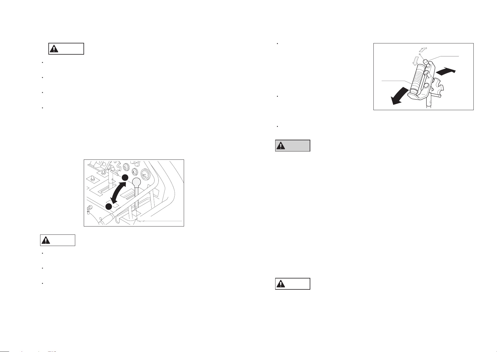
15-1. Crawler tension
Adjust the crawler tension by supplying grease to the grease cylinder. Make
adjustment so that the crawler tension will be the same on both sides.
CAUTION
15-2. Installation.removal of crawler
When removing the crawler, loosen the M14 bolt (width across flats: 22) on the
grease cylinder, remove the grease, return the front roller to the original position,
lift the crawler that is to be removed above the ground, and then remove the
crawler. Reverse the order of removal when installing the crawler. Refer to the
preceding paragraph for the crawler tension.
15-3. Prevention of crawler tearing loose
Be sure to check that the crawler is not slackened and the crawler tension is
adjusted appropriately before operation.
15-4. Greasing the crawler
The seesaw roller fulcrum shaft in the crawler section is provided with a grease
nipple. Supply grease to the nipple every 50 hours. Use Excelite EP2 grease or
equivalent to ISO VG2. (Refer to "Lubrication of friction surface of each part")
16. Adjustment of traveling section
Conduct the following work before adjusting the traveling section:
Remove the crawlers on both sides, or place the machine on a stable base to lift
the crawlers on both sides.
Remove the rear cover.
Excessive crawler tension will cause the front roller to lose the clearance, causing
the crawler to come off easily and the machine to break easily. Exercise care.
CAUTION
When lifting the machine, be sure to use an appropriate support to
completely secure the machine.
-23-

Lock nut
(left-hand thread)
Lock nut
(right-hand thread)
Lock shaft
Groove
Groove
Traveling lever
Neutral stopper
M10 right-/left-hand thread rods
16-1. Adjustment of neutral position of piston pump
Pump
Mounting bolt
Left neutral lever
mounting base for pump
Right neutral lever
mounting base for pump
2
1
3
4
1
2
3
Loosen the mounting bolts of the neutral lever mounting bases for the pump on
both sides to keep the bolts loose.
Return the side brake lever to unlock the traveling lever.
Start the engine, and move the neutral lever mounting bases for the pump by
using a stick, etc. to determine the neutral position.
CAUTION
The engine is rotating. Be careful of the pulley, belt, sprocket (crawler), etc. during
operation.
When the neutral positions of both bases are determined, stop the engine and
tighten the mounting bolts.
Start the engine again to check that the sprocket (crawler) will not rotate.
-24-
16-2. Adjustment of neutral position of traveling lever
Loosen all the lock nuts of the M10 right-/left-hand thread rods.
Turn the two rods at right and left to adjust the length so that the lock shaft of the
traveling lever will be set in the neutral stopper groove when the side brake is
pulled.
Tighten all the lock nuts of the rods and check that the traveling lever is locked
completely when the side brake lever is pulled and that the traveling lever is
unlocked quickly when the side brake lever is returned.

16-3. Confirmation after adjustment
1
2
3
1
2
3
4
After the above-mentioned adjustment, confirm the following:
Stop the engine and move the respective levers to check for interference.
Check that the machine is in the neutral position and will not move even if the
engine is in the full-throttle state.
(When the side brake lever is pulled and returned)
After moving the traveling lever to move the machine, release the traveling lever,
and check that the machine will not move.
Refer to the diesel engine operation manual for the method of handling
the engine.
CAUTION
There is a risk of a skin burn. Do not open the radiator cap during or right after
operation.
18. Hoisting and jacking up the machine
17. Engine
CAUTION
a) Use the low sulfur or ultra low sulfur diesel fuel (JIS No.2 diesel).
b) The machine is to be operated under severe condition such as vibration, slopes,
and dust. Change the entire engine oil 10 hours after the initial operation. Then
while continuing inspection and replenishment before use, change the entire
quantity every 100 hours thereafter.
Change all the oil filters simultaneously as well.
When using the machine in a dusty place, change oil and the oil filters more
frequency.
The quantity of the engine oil is 5.5 liters. Use the diesel engine oil in the service
class CD or above specified by the API standard.
c) When air is sucked in the fuel system of a diesel engine, the engine will not be
started. Inspect and maintain the diesel engine at all times to prevent entry
of air into the fuel system. Operation will be difficult when the fuel filter and
electromagnetic pump filter are clogged with dust or when water remains in them.
Drain water or clean filters every 50 hours. Replace filters with new ones every
200 hours.
d) Keep a pre-cleaner attached to the suction port of the air cleaner at all times
during operation. Be sure to clean the dust cup before operation.
e) Mix antiseptics (long-life coolant) into water, and put the mixture in the reserve
tank up to the MAX position as a radiator cooling water. Change the cooling water
every 50 hours. Check and supply the cooling water before operation. When the
temperature is likely to drop below the freezing point, use an antifreeze mixture.
When the radiator fins are clogged with dust, blow air to clean them.
(JIS No.2 diesel oil)
Precautions as to handling of engine
18-1. Hoisting
CAUTION
a) Qualification necessary to use a crane to hoist the machine
For hoisting the machine, follow the appropriate laws of the country where it is
hoisted.
b) Hoisting procedure
Lower the mower portion until it touches the ground.
Pull out the four hoisting hooks and secure them with pins. Hook the wire ropes
completely with shackles. Use wire ropes with sufficient strength. Be sure to
use four ropes of 2.5 m or more in length.
Pay attention to the position of the center of gravity during hoisting to balance
the machine sufficiently. Do not approach the machine inadvertently during
hoisting.
When lowering the machine, keep the machine horizontally and lower it in a
manner that the crawlers at right and left will touch the ground at the same time.
Impact applied to the traveling motor (sprocket) at that time will cause failure.
Precautions as to hoisting
-25-

-26-
Attachment
mounting base
Hitch sections
Lock pin mounting hole
Mower unit
1
2
3
4
(Front side)
(Rear side)
Jacking-up points
Jacking-up points
Bottom view of Main frame
18-2. Jacking up
When jacking up the machine with hydraulic jacks, apply jacks to the jacking-up
points on the following drawing.
19. Attaching/detaching the mower unit
CAUTION
Be sure to install and remove the mower unit in a flat horizontal place. Stop the
engine unless it is necessary to move the attachment mounting base up and down or
to move the machine forward and backward.
19-1. Removal of mower unit
Remove the intermediate shaft belt cover and right crawler cover, and then
remove the belt that connects the machine and the mower unit.
Pull out 6 clip pin and remove the lock pin.
Set the cylinder single-/double-acting changeover switch in the "double-acting"
position, and lower the attachment mounting base.
After confirming that the hitch sections are separated, slowly move the machine
backward, and the operation is complete.

19-2. Installation of the mower unit
1
2
3
4
While engaging the hitch sections, slowly move the machine forward, and raise
the attachment mounting base to engage the hitch sections.
After confirming that the hitch sections are engaged completely, attach the lock
pin and secure it with 6 clip pin.
Set the cylinder single-/double-acting changeover switch in the "single-acting"
position.
After attaching the belt and adjusting the tension, attach the right crawler cover
and intermediate shaft belt cover, and the operation is complete.
19-3. Hydraulic cylinder single-/double-acting changeover
CAUTION
Before starting ordinary operation, be sure to set the cylinder single-/double-acting
changeover switch in the "single-acting" position, and change it to the "doubleacting" position before installing or removing the mower unit.
Operation with the changeover switch in the "double-acting" position will cause
the hitch sections to be subjected to a load when the machine climbs over a large
stone or some other obstacle, causing machine failure.
20. Gear oil change for traveling motor
CAUTION
The speed reducer of the hydraulic motor for traveling is filled with 0.35 litter of gear
oil. Flush the speed reducer 50 hours after initial operation and every 200 hours after
that, and after each flushing, fill the speed reducer with a new gear oil #140 (ISO
VG140).
Unless the oil is changed according to the specified time, the motor failure will result.
Be sure to change oil as specified.
-27-

21. Wiring diagram
Glow timer
Glow
timer
Glow relay
Control timer
Control timer
Safety relay
Safety
relay
Relay N.C.Relay
N.C.
Relay
3
3
PE
S
L
R
1
6
6
7
5
5
4
4
2
3
1
4
2
3
1
4
2
Solenoid valve
for raising/lowering
mower portion
Solenoid valve
for holding
mower portion
Solenoid valve
for fan rotation
changeover
Solenoid valve
for fan
actuation
-CAUTION-
Relay
1243
5
6
43
1243
(M6)
5211 8912 6310 741 163452
Red
(AV5)
Yellow
(AV5)
Yellow
(AV5)
Yellow (AV0.85)
Green and red
(AV1.25)
Yellow
and red
(AV1.25)
Red and yellow
(AV2)
Red and yellow (AV2)
Red and yellow (AV0.85)
Blue and yellow
(AV0.85)
Yellow and black
(AV0.85)
Yellow
and blue
(AV0.85)
White and blue (AV0.85)
White
and black
(AV0.85)
Yellow and red (AV0.85)
Red and white (AV0.85)
Red and black (AV0.85)
Red (AV2)
Red (AV1.25)
Red (AV1.25)
Gray (AV1.25)
Red (AV2)
Red
Red (AV5)
Red
(AV0.5)
Sky blue (AV0.5)
Red
Red (AV2)
Red (AV3)
Black (AV2)
Black
(AV1.25)
Black
(AV1.25)
Black (AV3)
Black (AV0.85)
Black
(AV0.85)
Black (AV0.85)
Black
(AV0.85)
Black
(AV1.25)
Black (AV30)
Black (AV30)
Black (AV5)
Black
(AV0.85)
Black
(AV0.85)
Pink (AV3)
Black (AV1.25)
Blue
(AV1.25)
Blue (AV5)
Blue
(AV1.25)
Green
(AV1.25)
Green
(AV1.25)
Green (AV5)
Blue (AV0.85)
Green (AV1.25)
Green (AV0.85)
Green (AV0.85)
Green (AV1.25)
Brown (AV1.25)
Blue (AV1.25)
Blue
(AV1.25)
Black (AV0.5)
Black (AV3)
Black
Green (AV0.5)
Brown (AV0.5)
Brown (AV0.85)
Brown (AV5)
Black (AV1.25)
Black (AV1.25)
Red (AV1.25)
Black (AV1.25)
Black and
white (AV0.5)
Black
Black
(AV2)
Black
White and red (AV2)
Red and white (AV0.85)
Blue and white
(AV0.85)
Red and white
(AV0.85)
White and red (AV1.25)
White (AV5)
White
Black and yellow (AV0.85)
White and yellow (AV0.85)
White and blue
(AV1.25)
Blue and white (AV1.25)
Yellow and red
(AV0.85)
Yellow and red
(AV0.85)
White and red
(AV2)
White and
red (AV2)
White (AV2)
White (AV0.85)
White (AV0.85)
White (AV2)
White
White (AV0.5)
White
(AV2)
White
(AV2)
White
Yellow
and red
(AV1.25)
Yellow
and black
(AV0.85)
Yellow and black (AV0.85)
Yellow and blue
(AV0.85)
Red
and blue
(AV2)
Orange (AV0.85)
Red (AV0.85)
Black (AV2)
Starter switch connection
OFF
1
2
BMSG2
50A
50A
5A 5A 5A 5A 5A 5A 5A 20A 20A 5A
(M5)
(M5)
(M6)
(M4)
(M4)
B
S
M
G1
G2
4-pole ON-ON switch2-pole ON-OFF-ON switch
*
(M6)
(M6)
(M6)
(M6)
2
*
*
1
*
(M6)
1
*
(M6)
1
*
(M6)
(M6)
1
*
1
*
(M6)
(M8)
(M6)
1
*
1
ER
L
SP
*
1
*
*
(M6)
(M6)
(M12)
(M4)
(M5)
T (M6)
B1 (M5)
M (M8)
(M6)
(M4)
(M5)
(M5)
(M8)
(M5)
1
*
1
P
P
B
R
L
R
L
*
1
*
*
(M6)
(M6)
(M6)
2
*
1
1
2
3
3
4
7
5
6
2
1
4
*
*
Inclination
sensor
Electric
cylinder
Horizontal
controller
box
Fan control
unit
Safety
switch
Tank
unit
Fuel
gauge
E
-
+
E
B
S
Water
temperat ure
gauge
(Flat connector)
(Flat connector)
(Flat connector)
Alarm
buzzer
Fuel
pump
Thermo
switch
Thermo
switch
Emergency
switch
Brake
release
solenoid
Oil
pressure
lamp
Oil
pressure
switch
The wires with the same numberd mark are connected to one wire inside
the wiring system.
The single wires with mark without number and the wires connecting the
wires of the same numberd mark are connected to a grounding wire at the
back of the electric equipment box.
Starter
12V 80Ah/20HR
95D31R battery
Blue (AV5)
Blue
Engine
Solenoid
Glow plug
Glow
lamp
Charge
lamp
Alternator
-28-

MAG-18P-150MAG-18P-150
MA6AD661
PSV2-16A
SP08
Eng
166/166
VPF-06
KP1009
Hydraulic tank
(10 m)
CV-00630-50-00
Mower unit up/down(45-70-250 double-actingX2)
PF
PF
T3
T1 EAB
C
D
T1
(Refer to Valve module)
T1S
B2B1
IN
P1 P2
P2
T2
T2
P1
P2
T1
P1
P3
P4
PpPp
R/GR/G
T
EFEF
22. Hydraulic circuit
-29-

D
C
B
A
E
T2
T3
1
5
6
7
8
9
10
3
2
4
PF
EF
T1
9
1
2
3
4
5
6
7
8
10
No
Needle valve (throttling valve)
Check valve
Relief valve
Relief valve
Solenoid poppet valve
Solenoid poppet valve
Solenoid poppet valve
Solenoid valve
Solenoid valve
Solenoid valve
Name
for holding mower portion
for adjusting lowering speed
Unload for emergency
for cooling fan rotation changeover
for raising/lowering mower portion
for brake release
Use
Wiring No Connection
SOL ASOL B
A
B
T2
PF
T3
EF
T1
E
D
C
1
2
3
4
5
6
7
8
9
10
for cooling fan actuation
22-1.Valve module detail
-30-

The engine will not start.
(The starter motor does not work.)
Is the knife clutch disengaged?
Are respective fuses normal?
Is the battery output normal?
Are respective connections
of wiring normal?
Is the starter relay normal?
Disengage the knife clutch.
As safety mechanism, the engine cannot be
started when the knife clutch is engaged.
Refer to the battery operation manual.
Refer to the wiring diagram.
Execise due care in the handling of fuel.
Use of fire prohibited during fuel supply.
Check the fuel pump and the water sedimenter
filter.
Be sure to stop the engine before cleaning or
change.
Refer to the engine operation manual.
Change fuses.
Charge or replace the battery.
Connect the wire again.
Change the rela
y.
Supply fuel.
Change filters.
Clean or change the element.
Clean the precleaner.
Change solenoid.
Failure of main switch
Failure of control timer
Defective compression
Failure of main switch
Failure of starter motor
Defective grounding
Is fuel in the tank?
The engine will not start.
(The starter motor works.)
Is the fuel filter normal?
Is the air element normal?
Is the precleaner normal?
Is the fuel shut-off solenoid
normal?
YES
YES
YES
YES
YES
NO
YES
YES
YES
YES
Refer to the engine operation manual.
Refer to the engine operation manual.
Refer to the wiring diagram.
NO
NO
NO
NO
NO
NO
NO
NO
Fuse (5A・20A・50A)
23. Troubleshooting
23-1. Engine trouble
-31-

-32-
The engine starts, but it stops.
(It stops in approx. 5 seconds.)
Is the emergency switch
attached correctly?
Is the quantity of the engine oil
as specified?
Is the fan belt normal?
Attach correctly. Check the actuation before each use.
Engine oil specification :API standard Grade CF
or above.
Refer to the engine operation manual.
Refer to the wiring diagram. Pump ass’y
Refer to the engine parts catalog.
Check the fuel pump and the water sedimenter
filter.
Supply / replenishment
Set the belt again.
Check the wiring.
Replacement of fuel pump.
Replacement of filter.
Failure of control timer
Failure of oil pressure switch
Failure of alternator
Is the fuel pump operating?
The engine starts, but it stops.
(It stops some time later.)
Is the filter in the fuel pump normal?
YES
NO
YES
YES
YES
YES
Be sure to stop the engine before cleaning or
change.
Refer to the engine operation manual.
Refer to the engine operation manual.
Refer to the engine operation manual.
NO
NO
NO
NO
NO
Replacement of filter.
Clean or replace the element.
Clean the precleaner.
Defective compression
Is the fuel filter normal?
The engine starts,
but the output is low.
Is the air element normal?
Is the precleaner normal?
YES
YES
NO
NO

The machine will not run
even if it is operated
Is the quantity of hydraulic oil
as specified?
Is the V-belt normal?
Supply/replenishment
Recommended oil : SHELL TELLUS S3MT46
Refer to Belt adjustment.
Refer to the engine operation manual.
Refer to Belt adjustment.
Resetting/replacement
Failure of brake release solenoid valve
Failure of traveling motor
Change oil.
Engine maintenance
Resetting/replacement
Change filter.
Failure of hydraulic pump
(Failure of high-pressure relief valve)
Failure of traveling motor
Is the hydraulic oil clean?
The machine runs
but the power is low.
Is the engine rotation normal?
Is the V-belt normal?
Is the oil filter normal?
YES
YES
NO
YES
YES
YES
YES
Recommended oil : SHELL TELLUS S3MT46
Refer to Hydraulic circuit.
NO
NO
NO
NO
NO
23-2. Traveling system trouble
-33-

Fuse (5A・20A・50A)
The mower unit will not rises
or lowers
Is the fuse normal?
Are respective connections
of wiring normal?
Is the mowing height
adjustment switch normal?
Replacement of fuse.
Refer to the wiring diagram.
Reconnection.
Replacement of switch.
Failure of solenoid valve
Failure of hydraulic cylinder
Failure of flow dividing valve
YES
NO
YES
YES
NO
NO
The mower unit rises
but it does not lower.
Are respective connections
of wiring normal?
Is the mowing height
adjustment switch normal?
Is the throttle valve normal?
Reconnection. Refer to the wiring diagram.
Replacement of switch.
Adjustment of throttle valve.
Failure of solenoid valve
(Failure of check valve)
Failure of hydraulic cylinder
YES
NO
YES
YES
NO
NO
23-3. Mower unit trouble
-34-

The mower unit lowers
but it does not rise.
Are respective connections
of wiring normal?
Is the mowing height
adjustment switch normal?
Is the inside of mower unit
free of mud?
Reconnection. Refer to the wiring diagram.
Be careful of the knife during cleaning.
Repaire or replacement by specialist.
Refer to mower unit.
Replace the knife shaft assy with a normal one
while checking the knife balance.
Replacement of switch.
Cleaning
Removal/cleaning
Replacement of knife blade.
Damage of knife mounting hitch.
Damage of balance weight.
Distortion of knife shaft.
Failure of flow dividing valve
(Failure of relief valve)
Failure of hydraulic cylinder
Is the attachment free
from grass and dust?
Vibration of the mower unit
is substantial.
Stop work when the vibration
of the knife shaft assy is substantial.
Is the knife blade normal?
YES
NO
YES
YES
YES
YES
Be careful of the knife blade during cleaning.
NO
NO
NO
NO
Replacement of bearing.Is the bearing normal?
YES
NO
-35-

Fuse(5A・20A・50A)
Overheating occurs frequently.
Is the quantity of cooling
water as specified?
Are the radiation fins of the
radiator free from clogging?
Is the cooling fan
rotating normally?
Water supply/replenishment
The volume of water is approx.11L.
Use preservative together.
Exercise care so as not to damage
the radiation fins during cleaning.
Refer to the wiring diagram and hydraulic circuit.
Step control changeover switch is above
the electric equipment box in LH side cover.
Electric cylinder clamp . Cylinder mounting
shaft . Step mounting base shaft ass’y
Changeover switch wiring
Cleaning
Inspection of hydraulic
and electrical pages.
Failure of engine
(Failure of pump)
(Failure of water temperate
sensor)
Change to “AUTO”.
Replacement of fuse.
Replacement by normal parts.
Replacement of switch.
Breakage of bearing
Failure of electric cylinder
Defective connection of wiring
Is the control switch
in the “AUTO” position?
The step will not swing
on a slope.
Is the fuse normal?
Is the step/electric cylinder
support shaft normal?
Is manual operation possible?
YES
YES
YES
NO
YES
YES
YES
YES
Refer to the engine operation manual.
Refer to the wiring diagram.
NO
NO
NO
NO
NO
NO
23-4. Overheating
-36-
23-5. Step trouble

24. Checklist
Model Machine No.
Operating time
Judgment
Performance date
Operating time
Performance date
Operating time
Performance date
Operating time
Performance date
Operating time
Performance date
Memo
Notes Judgment Notes Judgment Notes Judgment Notes Judgment NotesItem
Inspector Inspector Inspector Inspector Inspector
Engine
(start/color of exhaust/number of revolutions)
Engine oil (quantity/cleanliness)
Engine oil filter
Air cleaner precleaner
(element)
Radiator (cooling water/radiation fin)
Fan belt tension
Fuel
(quantity/leakage)
Hydraulic oil (quantity/cleanliness)
Hydraulic oil filter
Tightening of hydraulic hose/joint
Traveling motor gear oil
(quantity/cleanliness)
Battery (qty of electrolyte/connection)
Operation of operation levers
Neutral position
Operation of emergency switch
Operation of step
Operation of switches and meters
Lighting of lamps
Operation of wires
Operation of knife tension parts
Operation of knife tension spring
Te nsion of V-belts
Rubber crawler
(tension/damage)
Condition of rotation of front and bottom rollers
Balance of knife shaft assy
Knife
(abrasion/breakage)
Vertical motion of mower unit
Damage to protective covers
Greasing of respective parts
Loosening of screws
Accumulation of dust
Damage to caution label
Damage to appearance
Symbol of judgment
. . . .
: Normal ; : Adjustment/correction ; : Repair/replacement
-37-

HMC156E-UM--GBZ/12H-00-S.K
Te l : (0533)84-1390
Fax : (0533)89-3623
Head Office
1-26, Miyuki-cho, To yokawa,
Aichi-Pref. 442-8530 Japan.
 Loading...