

BIG AIR KIT - Yamaha V-Star 1100
Page: 1BA-2041-00/01/03/06/07/13/13B
Revision: 3.6 - 04/02/2010
Install Time: 2 Hours
INCLUDED IN THE KIT:
(1) Jet Kit BA-2440-00
(1) Chrome Billet BAK Cover
(1) Re-usable Performance Air Filter
(1) Mounting Post
(1) M6 Fender Washer
(1) M6x12mm Chrome Cap Screw
(1) M5x10mm Stainless Button Head Screw
(1) 1/4 -20 Nut
(1) Oil Vent Line, Clear Poly
TOOLS REQUIRED:
3, 4 & 5 mm Allen Wrenches
CAUTION! We strongly recommend that a qualified technician install this kit
if you do not completely understand the instructions prior to the install.
(1) BAK Filter Raincoat
(1) M5 Stainless Steel Washer
(1) M6 Chrome Washer
(2) 1/4-28 x 1 13/16" Zinc Hex Head Bolts
(3) 1/4" Lock Washers
(1) Foam Filter Material, Green, Trapezoidal
(2) Filter Spacer, Aluminum
(1) Zip Tie 14"
(1) Mounting Arm SS
10 & 12mm Sockets
10mm Open-End Wrench
Pliers (Std. & Needle-nose)
Phillips & Flat Screwdrivers
Factory Service Manual
INSTRUCTIONS:
FIRST STEP: See instructions for installation of included with BA-2440VS Needle/Jet Kit and perform the
complete installation.
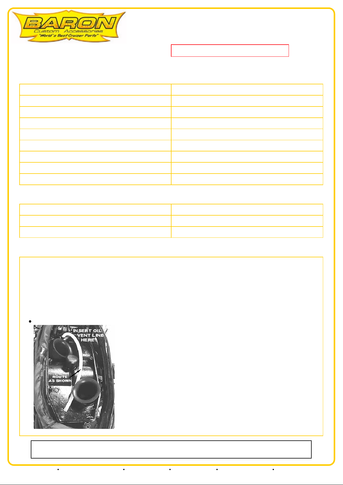
NOTE: The V-Star 1100 is prone to excessive oil blow-by from the crankcase vent that extends from the front cylinder head
to the black airbox above the carbs. To prevent excess oil deposits from leaking down into the BAK filter assembly and
blowing out the filter, you must install the supplied oil vent tube and foam filter element into the airbox as follows prior to
installing the new BAK filter assembly.
Loosen the (8) screws and (1) frame bolt holding the top of the black plastic airbox and remove the top.
Our install guides provide a basic outline on the proper installation of our products. Further tuning and/or
fitment may be required. Barons bears no responsibility on installation costs associated with this product.
© 2013 Barons Custom Accessories
5221 Oceanus Drive Huntington Beach, CA 92649 (925)583-2499 - Ph. (714)901-0520 - Fax www.baronscustom.com tech@baronscustom.com
BIG AIR KIT - Yamaha V-Star 1100
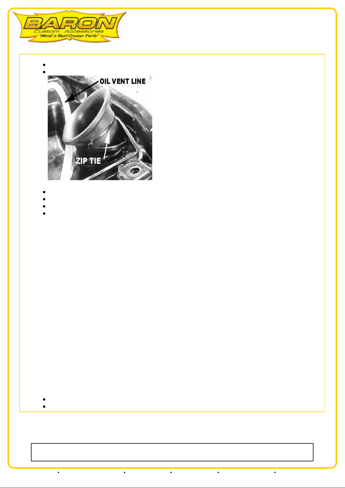
Insert supplied oil vent tube into crankcase breather inlet found at front of airbox.
Route this tube toward rear of airbox and secure to rear air horn with supplied zip tie as shown.
Page: 2BA-2041-00/01/03/06/07/13/13B
Install supplied breather foam in rear section of airbox under end of oil vent tube.
Trim foam with scissors as required for a proper, snug fit.
Reinstall top half of airbox and tighten frame bolt and all screws.
MAINTENANCE: Baron recommends the foam filter element be removed and cleaned at each air filter cleaning.
IMPORTANT NOTES: Check all linkages for interference, check all hoses for kinks, check all bolts and
hardware for tightness. Check throttle action for smooth operation before reinstalling the fuel tank.
1. The Baron Big Air Kit (BAK) comes un-assembled. First, place your performance air filter in the groove on
the cover; make sure the filter seats properly to make a complete seal. Now install the backing plate onto the air
filter, Again, align the filter with the groove in the backing plate. Secure with the two supplied 1/4-28 x 1 13/16"
zinc hex head bolts & lock washers. Install the supplied aluminum filter spacers onto the bolts between the back
plate and the cover. Blue Loctite® is recommended here.
2. Loosen the clamps holding the snorkel ("S" shaped air tube) connecting the stock air filter housing to the black
plastic airbox above carbs. Remove the two allen-head cap bolts that hold the stock air filter housing to the
engine and remove the stock air filter housing. Remove the snorkel.
3. Install the snorkel onto the backing plate of your new BAK filter assembly and secure the clamp. Install the
supplied BAK mounting arm to the rear of the backing plate with supplied M5 x 10mm button-head screw. Blue
Loctite® is recommended here.
4. Insert the mounting post from the BAK backing plate into grommet on the side of the engine and secure with
supplied 1/4 -20 nut and washer. Slide the snorkel onto the air inlet on the black plastic airbox above carbs.
Install air filter mounting bolt (M6 x 12mm) through mounting arm and tighten. Now tighten snorkel clamp at
air inlet on the black plastic airbox.
IMPORTANT NOTES: Check all linkages for interference, check all hoses for kinks, check all bolts and
hardware for tightness. Check throttle action for smooth operation.
Reinstall the fuel tank.
Perform final idle mixture screw adjustment per instructions supplied with Barons Jet Kits.
Our install guides provide a basic outline on the proper installation of our products. Further tuning and/or
fitment may be required. Barons bears no responsibility on installation costs associated with this product.
© 2013 Barons Custom Accessories
5221 Oceanus Drive Huntington Beach, CA 92649 (925)583-2499 - Ph. (714)901-0520 - Fax www.baronscustom.com tech@baronscustom.com

Page: 3BA-2440VS
NEEDLE/JET KIT - Yamaha V-Star 1100 Custom & Classic
(99-10)
Revision: 2.7 - 02/19/2010
CAUTION! We Strongly recommend that a qualified Yamaha Technician
install this kit since the carburetors must be removed from the motorcycle.
Install Time: 2 Hours
INCLUDED IN THE KIT:
(4) Mikuni Main jets (107.5, 110, 112.5, 115)
(2) Mikuni Pilot jets (2x22.5)
(2) Baron Adjustable Needles
(2) "e" Clips
(8) Cap-head Allen Screws
TOOLS REQUIRED:
3, 4 & 5mm Allen Wrenches
10 & 12mm Sockets
10mm Open-end Wrench
Phillips & Flat Screwdrivers
Pliers (Std. & Needle-nose)
5/32" Drill Bit and Drill
Self tapping Sheet-metal Screw
Yamaha Service Manual
INSTRUCTIONS:
1. You will need to remove and disassemble the following components: Fuel Tank - Factory Airbox - Carburetors per Yamaha shop
manual procedures. Note: Always perform internal carburetor work in a clean area. Work on one carb at a time!
2. Remove the screws on the plastic cap of one carburetor, and pull the vacuum slide.
3. Remove the OEM needle, spacer and any washers that may sit under the stock "e" clip, noting order of assembly. (Note; washers are
sometimes used as shims to raise the needle, each is equivalent to 1/2 clip position, if your bike has these washers then you must reuse them
under the new "e" clip of the adjustable needles)
4. Counting from down from the top (The blunt end closest to the grooves) of the adjustable needle, install new "e" clip in the #4 slot of new
adjustable Baron Needle.
5. Reinstall the OEM spacer and washers as shown in the figure below.
6. Reinstall the vacuum slide along with the diaphragm spring and reattach the diaphragm cover. Verify the slides maintain their full range
of movement and do not bind.
7. Drain the fuel from the float bowls and remove the bowl covers. Take care as these screws are very soft and are prone to stripping, use
the correct size phillips screwdriver and put firm pressure on the heads as you turn. Replacement allen screws are included in the kit.
8. Remove the OEM jets and replace them with Barons supplied Mikuni jets as indicated below. Make sure the front cylinder's
carburetor gets the larger size main jet as indicated below.
NOTE: 2006-up bikes come with the proper main jets. They will flow more fuel with our needles but will require the included larger pilot
jets.
IMPORTANT: Baron jet and clip recommendations best suit average riding. Differences in weather, altitude or modifications to your
exhaust system may require jets other than those supplied.
Our install guides provide a basic outline on the proper installation of our products. Further tuning and/or
fitment may be required. Barons bears no responsibility on installation costs associated with this product.
© 2013 Barons Custom Accessories
5221 Oceanus Drive Huntington Beach, CA 92649 (925)583-2499 - Ph. (714)901-0520 - Fax www.baronscustom.com tech@baronscustom.com

NEEDLE/JET KIT - Yamaha V-Star 1100 Custom & Classic
(99-10)
USE THE FOLLOWING MAIN JETS AS INDICATED BELOW:
Stock Air Filter/Pipes: 112.5 F 110 R
Aftermarket Filter/Pipes: 115 F 112.5 R
F=Front cylinder, R=Rear cylinder
High altitude above 5000 applications may require the use of one size smaller/leaner jets.
All 1100's use the richer Pilot Jets supplied in the kit.
9. Thoroughly clean the inside of the float bowls prior to reinstalling them.
Page: 4BA-2440VS
10. Reassemble the carburetors by reversing the order of step #1 through step #9. Use the new supplied cap head allen screws in
place of the OEM Phillips head screws for the float bowls.
11. Locate the air/fuel mixture screw in each carb. You will see either a screw head or a brass plug.
If it is a screw head, skip to step #11c. If you see a brass plug with a small hole in the center, proceed as follows:
With a 5/32" drill bit, carefully and slowly drill through the fuel mixture plugs.
CAUTION! The fuel mixture screw is directly under this plug. Be prepared to stop the drill the INSTANT you break through the
plug or you may destroy the screw.
Insert a self-tapping sheet metal screw into the drilled hole and remove the plugs.
With air/fuel screw now accessible, use a flat blade screwdriver to turn the screw clockwise until it lightly seats, then carefully turn it
counter-clockwise 4 turns.
Refer to step #16 for assistance in fine-tuning the setting of the air/fuel adjustment screw. Do this to both carburetors. 12. Reinstall
the carburetors.
13. Reconnect the fuel lines, ensuring the clamps are firmly in place.
14. Reinstall all vent hoses and electrical connectors that were previously removed, checking for any obstructions or blockage.
15. Reinstall the OEM air filter assembly or, if you are installing our Big Air Kit (BAK), follow the instructions that accompany that
kit and then continue with step #16.
16. Verify proper throttle operation before starting the vehicle. Make sure the cables are not binding.
17. The adjusting procedure requires the use of carburetor sticks or a set of vacuum gauges. The carburetors must be synchronized
in order to achieve optimum performance. This procedure should be performed by a qualified Yamaha repair technician. Verify that
the air/fuel adjustment screw has been set to a starting position as described in step #11c, and that the clip has been installed as
detailed in step #4. Check the engine at idle speed for any popping or back firing. For best results, we recommend the air/fuel
mixtures be adjusted with an Exhaust Gas Analyzer (EGA) to a CO reading between 2% and 3%.
Our install guides provide a basic outline on the proper installation of our products. Further tuning and/or
fitment may be required. Barons bears no responsibility on installation costs associated with this product.
© 2013 Barons Custom Accessories
5221 Oceanus Drive Huntington Beach, CA 92649 (925)583-2499 - Ph. (714)901-0520 - Fax www.baronscustom.com tech@baronscustom.com
 Loading...