

BARNSTEAD|THERMOLYNE D7421, D7422-33, D7423, D7422, D7428 Installation, Operation & Service Parts Manual
...Page 1

1
EASYpure™ RO
Reverse Osmosis System
SERIES 742
INSTALLATION,
OPERATION,
SERVICE AND REPAIR MANUAL,
AND PARTS LIST
LT742X16 • 8/20/97
Model Voltage
D7421 120
D7422 240
D7422-33 230
D7423 100 Low Pressure
D7428 120 Low Pressure
D7429 240 Low Pressure
D7429-33 230 Low Pressure
BARNSTEAD|THERMOLYNE CORPORATION
Page 2
2
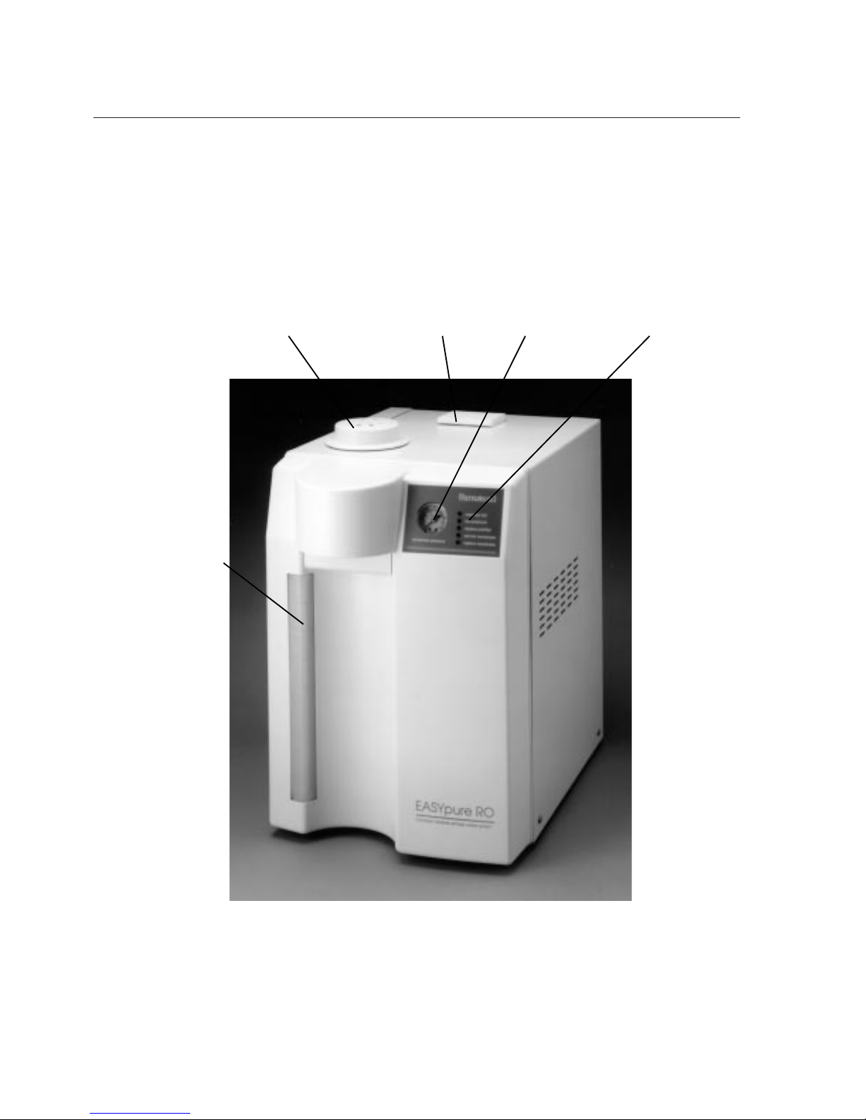
Figure 1 EASYpure RO
Ventgard
Back
Door
Latch
Pressure
Gauge
Indicator
LED's
Tank
Water
Level
Sight
Page 3

3
Table of Contents
Safety Information ........................................................................................................................................4
Alert Boxes................................................................................................................................................4
Warnings....................................................................................................................................................4
Specifications................................................................................................................................................6
Feedwater Requirements1........................................................................................................................6
Product Water Specifications ....................................................................................................................6
Electrical Requirements ............................................................................................................................6
Environmental Conditions..........................................................................................................................6
Product Water Rejection Rates....................................................................................................................6
Declaration of Conformity ............................................................................................................................7
Unpacking ....................................................................................................................................................8
Installation ....................................................................................................................................................9
Locating your EASYpure RO ....................................................................................................................9
General Usage ..........................................................................................................................................9
Bench Mounting ......................................................................................................................................10
Wall Mounting..........................................................................................................................................11
Utility Connections ..................................................................................................................................12
Feedwater Connection ........................................................................................................................12
Reject Water Connection ....................................................................................................................13
Tank Overflow Connection ..................................................................................................................14
Connections to Equipment Supplied By the EASYpure RO. ..................................................................15
Installing The Prefilter and Membranes ..................................................................................................16
Prefilter Installation ..............................................................................................................................16
Membrane Installation..........................................................................................................................17
Electrical Connections ............................................................................................................................20
Membrane Flush......................................................................................................................................20
Set "Replace Prefilter" Indicator ............................................................................................................21
Operation....................................................................................................................................................24
Indicators ................................................................................................................................................24
Pressure Gauge ..................................................................................................................................24
LED's....................................................................................................................................................24
Maintenance ..............................................................................................................................................27
Caring For Your EASYpure RO ..............................................................................................................27
System Sanitization ..............................................................................................................................27
Ventgard® Filter Replacement ............................................................................................................30
General Cleaning Instructions ..............................................................................................................30
Service and Repair ....................................................................................................................................31
Normal Unit Operation ............................................................................................................................31
Fuse Replacement ..............................................................................................................................33
Membrane Replacement......................................................................................................................33
Prefilter Replacement ..........................................................................................................................34
Parts List ....................................................................................................................................................35
Recommended Spares ........................................................................................................................35
Ordering Procedures............................................................................................................................37
Troubleshooting..........................................................................................................................................38
Wiring Diagrams ........................................................................................................................................39
Exploded View............................................................................................................................................42
Exploded View Key ....................................................................................................................................43
One Year Limited Warranty ........................................................................................................................44
Page 4
4
Safety Information
Your Barnstead EASYpure RO has been designed
with function, reliability, and safety in mind. It is
your responsibility to install it in conformance with
local electrical codes. For safe operation, please
pay attention to the alert signals throughout the
manual.
Warnings
To avoid electrical shock, always:
1. Use a properly grounded electrical outlet
of correct voltage and current handling
capacity.
2. Do not mount the EASYpure RO directly
over equipment that requires electrical
service. Routine maintenance of this unit
may involve water spillage and subsequent electrical shock hazard if improperly
located.
3. Replace fuses with those of the same type
and rating.
4. Disconnect from the power supply prior to
maintenance and servicing.
To avoid personal injury:
Warning
Warnings alert you to a
possibility of personal injury.
Caution
Cautions alert you to a
possibility of damage to the
equipment.
Note
Notes alert you to pertinent
facts and conditions.
Alert Signals
Page 5

5
S
AFETY INFORMATION
1. Do not use in the presence of flammable or
combustible materials; fire or explosion may
result. This device contains components
which may ignite such materials.
2. Ensure all piping connections are tight to
avoid leakage of chemicals.
3. Ensure adequate ventilation when using
chemicals for cleaning.
4. Follow carefully the manufacturers’ safety
instructions on labels of chemical containers
and Material Safety Data Sheets (M.S.D.S.).
5. Refer servicing to qualified personnel.
C. To ensure safe mounting:
1. Wall composition and construction, as well
as fastener type, must be considered when
mounting this unit. The mounting surface
and fasteners selected must be capable of
supporting a minimum of 120 lbs.; inadequate support and/or fasteners may result in
damage to mounting surface and/or equipment. If you are unsure of mounting surface
composition, condition and construction, or
correct fasteners, consult your building
maintenance group or contractor.
Page 6

6
Specifications
Dimensions
30.5 cm W x 46.7 cm W x 46 cm H.
Feedwater Requirements
1, 5
Max. Temperature........................48.8°C
Min. Pressure (standard unit) ......30 psig
(2.1 bar)
Min. Pressure (low pressure unit) 9 psig
(0.62 bar)
Max. Pressure (standard unit) ......100 psig
(6.8 bar)
Max. Pressure (low pressure unit)
15 psig (1.1 bar)
Inlet Flow Requirements ..............53.5 lph
pH ................................................4 - 11
TDS (Max. ppm as CaCO3) ........500
Silt Density Index ........................<5%
Free Chlorine................................<0.1 ppm
2
Langlier Saturation Index ............Negative
Turbidity........................................<1 NTU
Iron (Total as Fe)..........................<0.5 ppm
Product Water
Specifications
5
Product Water Flow Rate ............12 lph
3
% Recovery..................................20%-26%
1 Feedwater suitability must be determined by a water analysis.
2 Free chlorine removed by pretreatment cartridge.
3 ±1.5 lph, feedwater at 25°C and 60 psig pressure.
4 Membrane performance is dependent on condition, pressure, recovery, water temperature and water composition. Listed membrane
performance for a new membrane is based on optimum operating conditions of 60 psig, 15% recovery, 25°C (77°F) feedwater temperature and feedwater composition of a maximum of 500 ppm NaCl at a pH of 6.0-6.5.
5 Membrane performance, flowrates and recovery information are nominal values. Variations in the feedwater temperature, pumps and
reject orifice may slightly alter these results.
Membrane Rejection Rates
4
Monovalent Ions ..........................90-95%
Polyvalent Ions ............................95-99%
Particles........................................>99%
Microorganisms............................>99%
Dissolved Organics (300 MW) ....>99%
Reject Water Flow Rate 650 ml/min
at
60 PSIG ±5
PSIG
Electrical Requirements
Model D7422-33 - 230 VAC ±10%, 47-63 Hz
Model D7429-33 - 230 VAC ±10%, 47-63 Hz
Environmental Conditions
Operating: 17°C - 27°C; 20% - 80% relative
humidity, non-condensing. Installation
Category II (over-voltage) in
accordance with IEC 664. Pollution
Degree 2 in accordance with IEC
664. Altitude limit: 2,000 meters.
Storage: -25°C - 65°C; 20% - 80% relative
humidity.
Page 7

7
Declaration of Conformity
Barnstead|Thermolyne hereby declares under its sole responsibility that this product conforms with the technical requirements of the following standards:
EMC: EN50081-1 Generic Emission Standard; EN 50082-1 Generic Immunity
Standard.
Safety: IEC 1010-1-92 Safety requirements for electrical equipment for measurement, control and laboratory use; Part 1: General Requirements
per the provisions of the Electromagnetic Compatibility Directive 89/336/EEC, as amended
by 92/ 31/EEC and 93/68/EEC, and per the provisions of the Low Voltage Directive
73/23/EEC, as amended by 93/68/EEC.
The authorized representative located within the European Community is:
European manager
Barnstead|Thermolyne
Saarbrückener Str. 248
D-38116 Braunschweig
Germany
Copies of the Declaration of Conformity are available upon request.
Page 8

8
Unpacking
Carefully remove the unit from its shipping container.
The following items are shipped separately and
must be removed from the packaging prior to discarding the packaging:
1. EASYpure RO Ventgard air filter.
2. Power cord.
3. Pump interlock cord.
4. Membrane bypass tubing.
The following items are located inside the membrane access door:
1. Feedwater tubing.
2. Reject water tubing.
3. Product tubing to connect accessory
reservoir.
4. Product tubing to connect another
EASYpure unit.
Page 9
9
Locating your EASYpure RO
Your EASYpure RO must be located within six feet
of an electrical outlet appropriate for your unit, within five feet of your feedwater supply and close to
an atmospherically vented drain. If you are using
the accessory 30 Liter Reservoir (Part Number
TY742X2A), the tank overflow on the EASYpure
RO's integral 6.5 liter tank should be located below
the level of the storage reservoir's overflow. This
will ensure that the EASYpure RO's internal float
switches will control the operation of the system. If
the EASYpure RO is to be used with the accessory 30 Liter Reservoir, the reservoir must not be
mounted farther than 4 feet away from the
EASYpure RO. The EASYpure RO Bench Stand
(Part Number D7424) will be required for a bench
mounted installation with an accessory 30 Liter
Reservoir.
General usage
Do not use this product for anything other than its
intended usage.
Do not mount the EASYpure
RO directly over equipment
that requires electrical service. Routine maintenance of
this unit may involve water
spillage and subsequent
electrical shock hazard if
improperly located.
Warning
Installation
Page 10

10
I
NSTALLATION
Bench Mounting
If you are bench mounting the EASYpure
RO without the accessory 30 Liter Reservoir
(Part Number TY742X2A), simply place the
EASYpure RO on a bench.
If you are bench mounting the EASYpure
RO and using it in conjunction with the
accessory 30 Liter Reservoir (Part Number
TY742X2A), the EASYpure RO Bench Stand
(Part Number D7424) must be added to the
EASYpure RO to ensure automatic operation. Install the EASYpure RO Bench Stand
as follows:
1. Remove the 4 feet from the
EASYpure RO and retain the
screws.
2. Place the EASYpure RO on the
Bench Stand so that the screw
holes where the feet were attached
line up with the holes in the Bench
Stand.
3. Install the 4 screws removed in
step 1 through the bottom of the
Bench Stand and into the
EASYpure RO.
4. Install the accessory 30 Liter
Reservoir according to the instructions in the accessory 30 Liter
Reservoir manual.
Page 11
11
Wall Mounting
If you are wall mounting the EASYpure RO using
the optional wall mounting bracket, mount the unit
as follows:
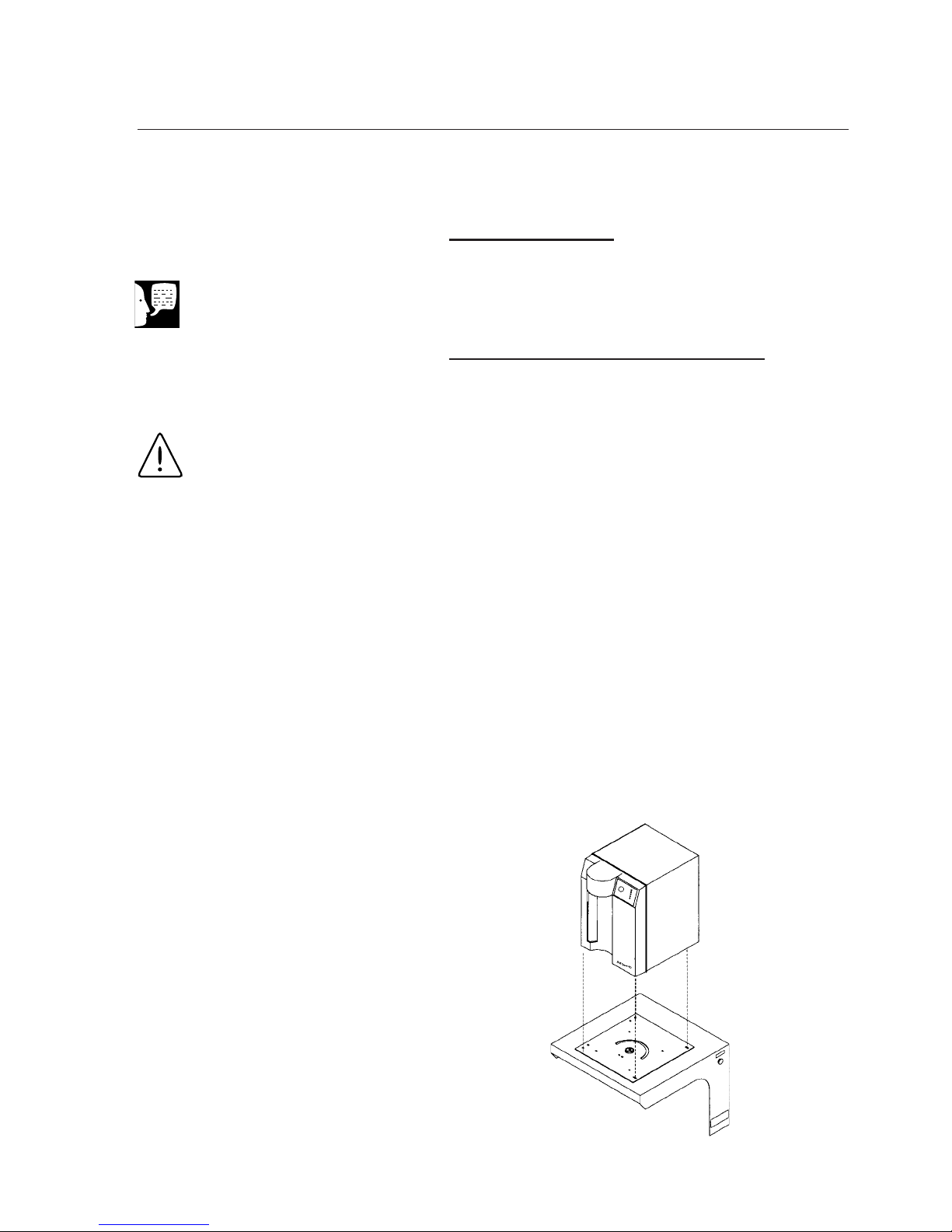
Wall Mounting the EASYpure RO
1. Install the wall bracket (Part Number
D7384) on the wall in a location that is
accessible to water, power and an atmospherically vented drain, and that is convenient to use. Aminimum of 4 fasteners
must be used.
2. Remove the 4 feet from the EASYpure
RO. Retain the screws.
3. Place the EASYpure RO on the wall
bracket swivel base so that the screw
holes where the feet were attached line up
with the holes in the wall bracket. There
are guides on the wall bracket that will
mate with the EASYpure RO.
I
NSTALLATION
Figure 2 Wall Mounting the EASYpure RO
Wall composition and construction, as well as fastener
type, must be considered
when mounting this unit. The
mounting surface and fasteners selected must be capable
of supporting a minimum of
120 lbs.; inadequate support
and/or fasteners may result in
damage to mounting surface
and/or equipment. If you are
unsure of mounting surface
composition, condition and
construction, or correct fasteners, consult your building
maintenance group or contractor.
Do not mount the EASYpure
RO directly over equipment
that requires electrical service. Routine maintenance of
this unit may involve water
spillage and subsequent electrical shock hazard if improperly located.
Note
If you are bench mounting the
unit, proceed to Utility
Connections.
Warning
Page 12
12
4. Install the four screws removed in step 2
through the bottom of the wall bracket and
into the EASYpure RO.
Utility Connections
The EASYpure RO is supplied with four separate
lengths of tubing to be used for feedwater, reject
water, feed to accessory storage reservoir and feed
to another EASYpure unit's connections. Each
length of tubing is six feet long and has the necessary fittings installed.
Feedwater Connection
1. Locate the length of 3/8" O.D. tubing provided with a quick disconnect insert on
one end and a 3/8" O.D. X 1/4NPT tubing
adapter on the other.
2. Insert the quick disconnect insert into the
feedwater inlet on the EASYpure RO.
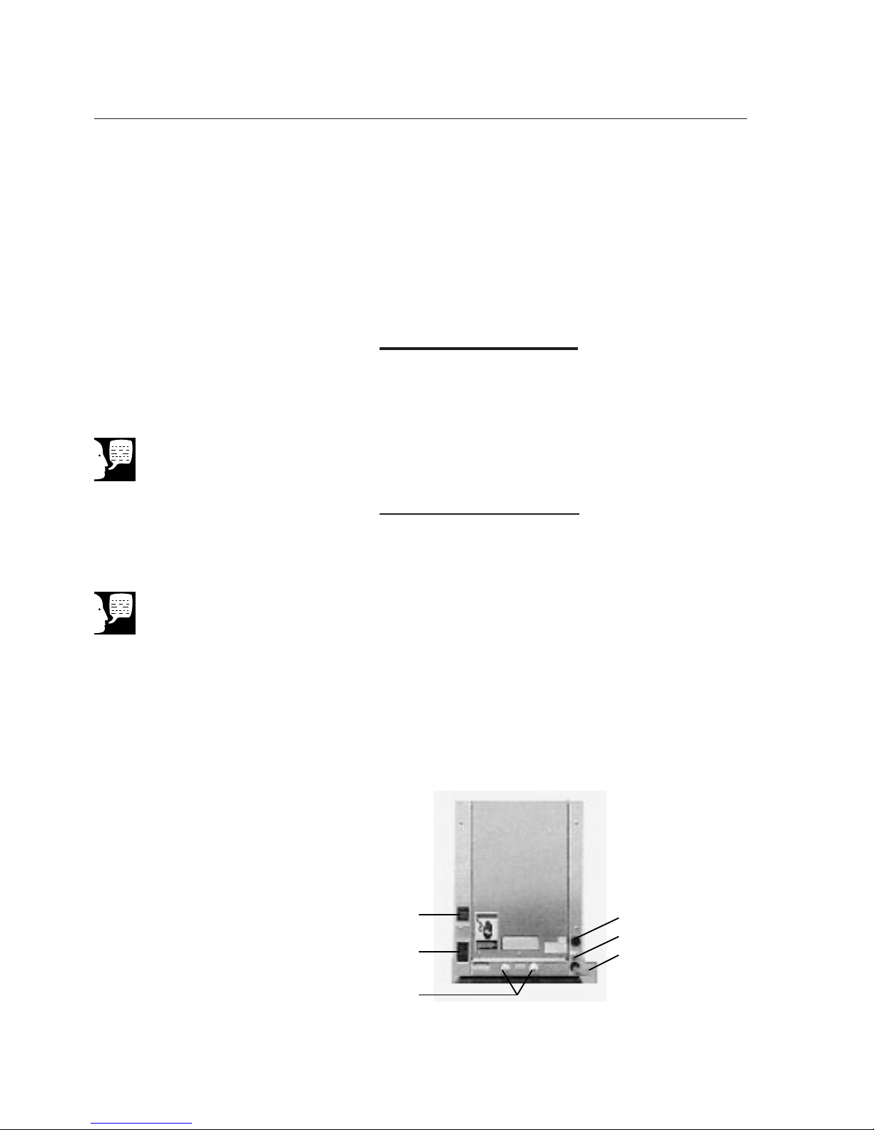
(See Figure 3 for location.) Install the tubing adapter onto your incoming water line.
We recommend a customer supplied shut
off valve be installed in your feed water
line.
I
NSTALLATION
Power Entry
Module/
ON-OFF Switch
Product
Water
Outlets
Pump
Interlock
Tank Overflow
Reject Water Connection
Feedwater Inlet
Figure 3 Connections
Note
We recommend a customer
supplied shut off valve be
installed in your feed water
line.
Note
The quick disconnect fittings
have built-in shutoff valves in
both the coupling and the
insert.
Page 13
13
Reject Water Connection
1. Locate the reject water tubing. This is the
piece of 3/8" O.D. tubing that has an
adapter on one end and no connector on
the other end. Remove the nut, grab ring,
backup ring and o-ring from the reject
water fitting located at the lower right of
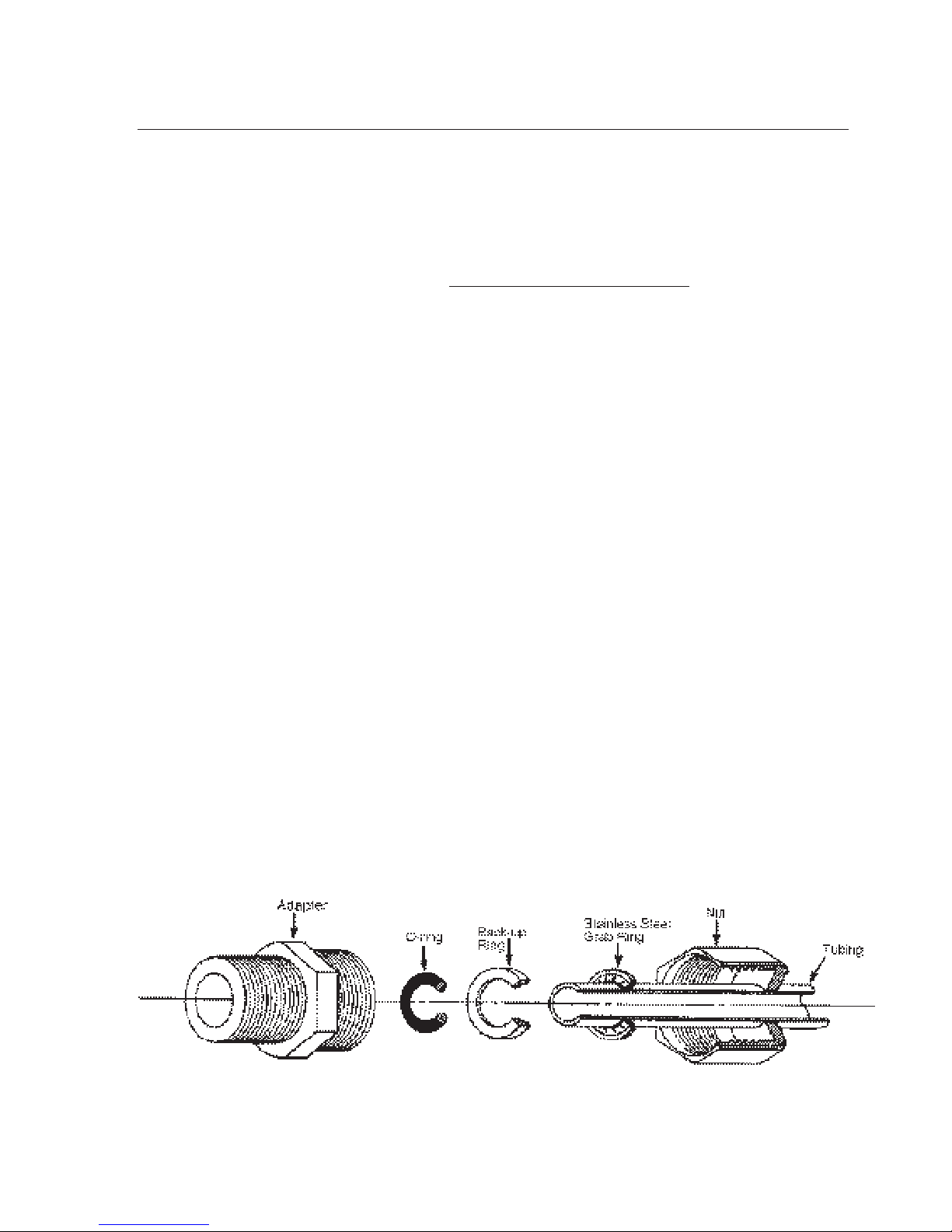
the unit. (See Figure 4 for part identification and Figure 3 for fitting location.)
2. Thread the nut, grab ring and backup ring
on the reject adapter. Do not use the oring at this time.
3. Push the tubing through the hex nut until it
bottoms out in the adapter.
4. Remove the adapter nut and tubing. Place
the o-ring over the tubing. Be careful not
to push the backup ring or grab ring further back on the tubing when installing the
o-ring. Connect the tubing to the reject
connection on the EASYpure RO.
I
NSTALLATION
Figure 4 Typical Polypropylene Tubing Adapter Installation
Page 14

14
5. Route the other end of the reject
water tubing with the adapter
installed to an atmospherically
vented drain. Ensure there are no
kinks in the tubing and that it proceeds in a downward plane.
6. If possible, use the tubing adapter
to permanently install the reject
water tubing in the drain.
Tank Overflow Connection
1. Refer to Figure 3 and attach a customer supplied hose barb connector and 5⁄8" O.D. tubing to the tubing located at the lower right of the
unit as you look at the rear of the
unit.
2. Route tubing to an atmospherically
vented drain. Ensure there are no
kinks in the tubing and that it proceeds in a downward plane.
I
NSTALLATION
Page 15
15
Connections to Equipment
Supplied By the EASYpure
RO.
Your EASYpure RO also includes two
lengths of tubing with quick disconnect
inserts attached. One is 1/4" O.D. tubing and
one is 3/8" O.D. tubing. Use the 1/4" tubing
to feed directly from the EASYpure RO to
another EASYpure unit. Use the 3/8" O.D.
tubing to feed the accessory 30 Liter
Reservoir if one is being used.
1. Install the quick disconnect insert
attached to the tubing into one of
the product water quick disconnect
couplings on the EASYpure RO.
(See page 11.)
2. Install the other end of the tubing
into the unit being fed by the
EASYpure RO according to the
instructions in that unit's manual.
3. Locate the pump interlock cord
supplied with the EASYpure RO.
Plug one end of the pump interlock
cord into the pump interlock on the
EASYpure RO. (See page 11.)
Remove the jumper plug from the
pump interlock on the other
EASYpure unit and save it for
future use. Plug the other end of
the cord into the pump interlock on
the other EASYpure unit.
I
NSTALLATION
Do not connect the product water
tubing to a connected EASYpure unit
until you have completed the membrane flush procedure for the
EASYpure RO.
Note
The product water quick disconnect inserts can be
installed in either product water
quick disconnect coupling. The
quick disconnect ends of the
inserts are the same size.
Note
Note
If you are not now feeding another
EASYpure unit, save the pump
interlock cord for possible future
use.
Page 16

16
Installing The Prefilter and
Membranes
1. Disconnect the unit from the power
supply.
2. Pull the rear side of the door latch
up and toward the front of the unit
until the front of the door latch
unhooks.
3. Lift the front of the door latch and
open door.
Prefilter Installation
Chlorine and particulates will damage your
membranes, resulting in premature membrane failure. Therefore, your EASYpure RO
uses an extruded carbon prefilter to remove
chlorine and particulates from your feed
water.
Install the prefilter as follows:
1. Remove a new prefilter (Part
Number D50246) from its plastic
bag.
I
NSTALLATION
Page 17
17
2. Wet the o-rings on both end caps
of the prefilter.
3. Insert the upper end cap into upper
center position until it bottoms out
in the connector. (The upper end
cap is the one with the right angle
turn and the two flanges.) The two
flanges on the end cap slide down
on each side of the keyway wall.
(See Figure 7.)
4. Lower the prefilter and insert the
lower end cap into the lower center
socket until it is firmly seated.
Membrane Installation
1. Remove the membrane bypass
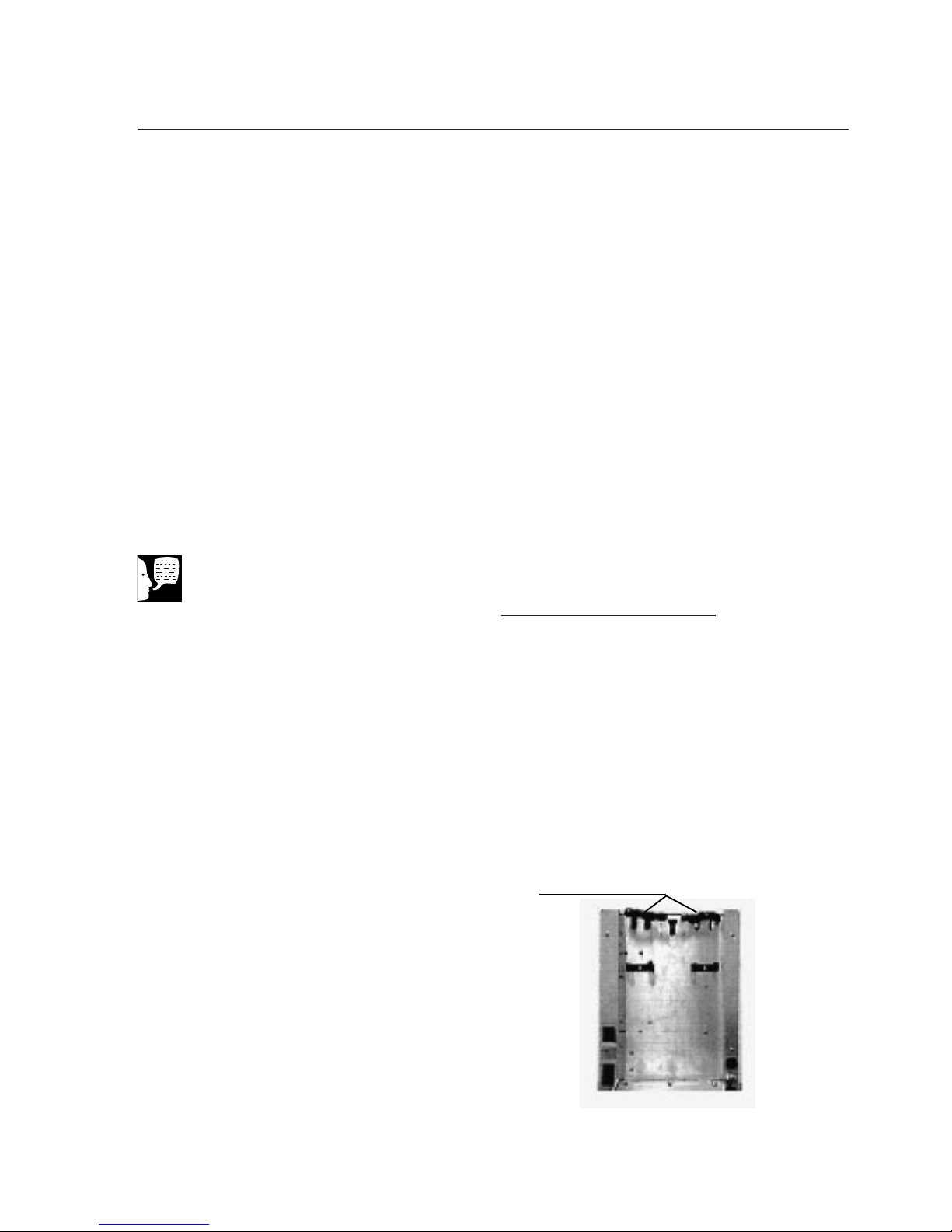
tubing from the EASYpure RO (see
Figure 5). The membrane bypass
tubing may be stored inside the
EASYpure RO case for easy
access when needed for the system sanitization procedure.
I
NSTALLATION
Figure 5 Membrane Bypass Tubing Installed
Membrane By-Pass Tubing
Note
The membrane by-pass tubing will
be needed for sanitizing the
EASYpure RO. Do not discard it.
Page 18
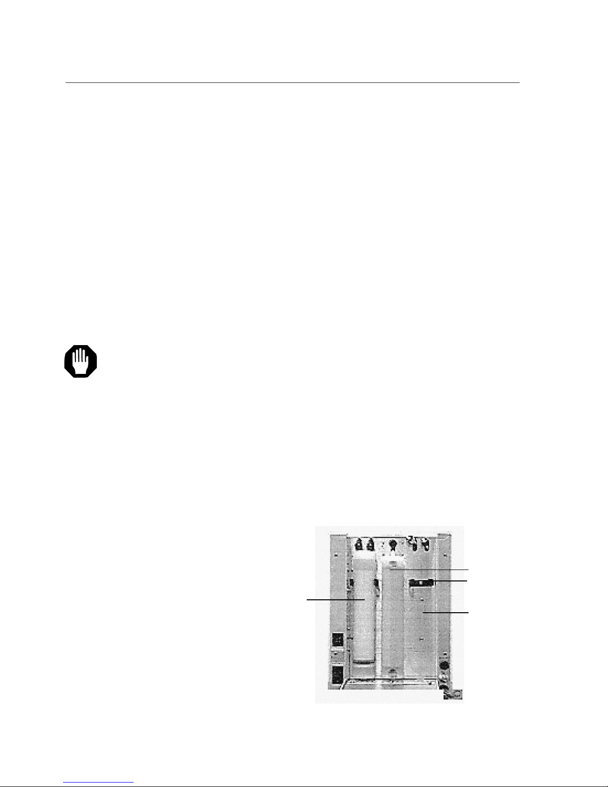
18
2. Remove an RO membrane cartridge (Part Number D7425) from
its plastic bag.
3. Remove the nut, stainless steel
grab ring, backup ring and o-ring
from the connectors on the membrane.
4. Connect the product and reject
tubes in the right-hand membrane
position on the EASYpure RO to
the product and reject outlet connectors on the RO membrane cartridge. Ensure that the o-ring, backup ring, stainless steel grab ring
and nut are in place on the product
and reject tubing on the EASYpure
RO (see Figure 4, page 12).
Ensure that the product tube is
connected to the product connector
and the reject tube is connected to
the reject connector. Hand-tighten
the connections.
I
NSTALLATION
Figure 6 Proper Position of Prefilter and Membranes
Prefilter
Right-hand
Membrane
Position
Left-hand
Membrane
Spring Metal
Membrane Retainer
Do not use a wrench on the
tubing adapter connections.
A sufficiently tight connection
can be made by hand.
Caution
Page 19
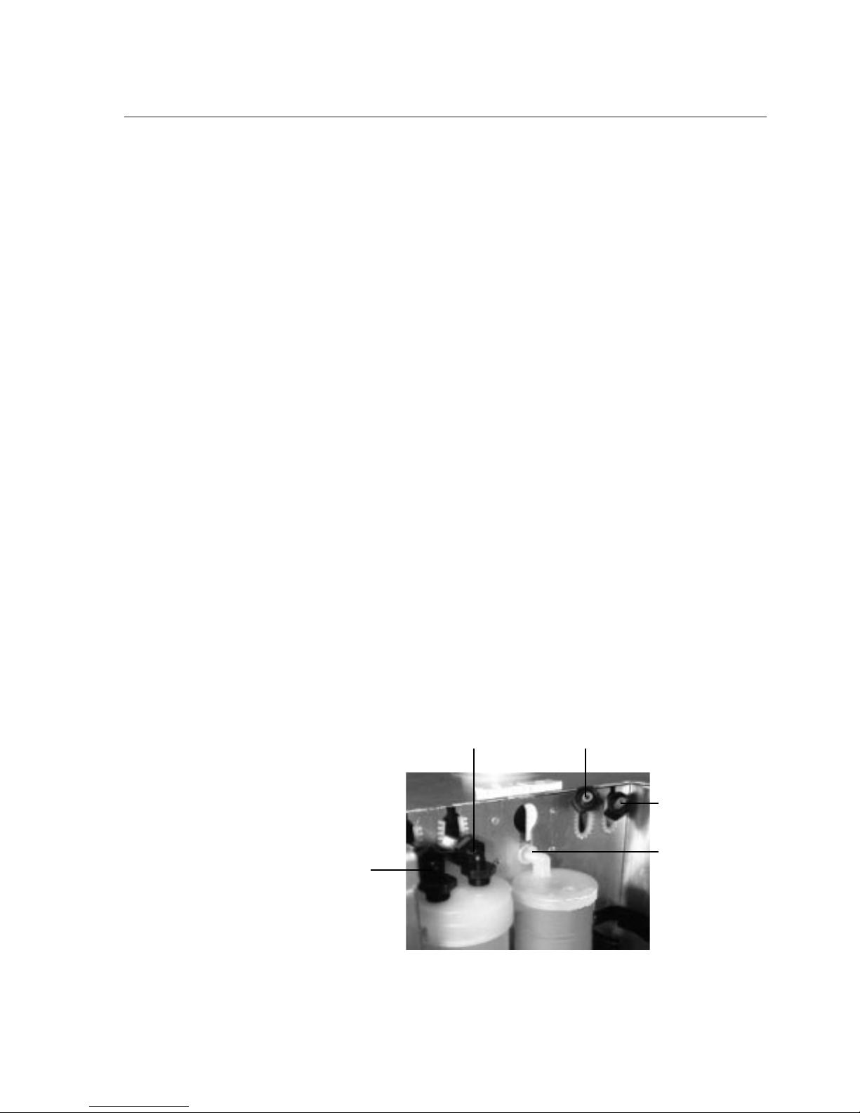
19
5. Wet the o-rings on the bottom of the membrane cartridge. Insert the RO membrane
cartridge into the right-hand spring metal
retainer.
6. Slide the RO membrane cartridge down
until the lower end cap is firmly seated in
the lower right-hand socket.
7. Remove the second RO membrane cartridge (Part Number D7425) from its plastic bag. Install the second membrane in
the left hand membrane position following
the instructions in steps 3-6 above for the
left hand connections.
8. Close and latch membrane access door.
I
NSTALLATION
Figure 7 Prefilter and Membrane Connections
Product
Reject
Flanges on
either side of
keyway wall
Product
Reject
Page 20
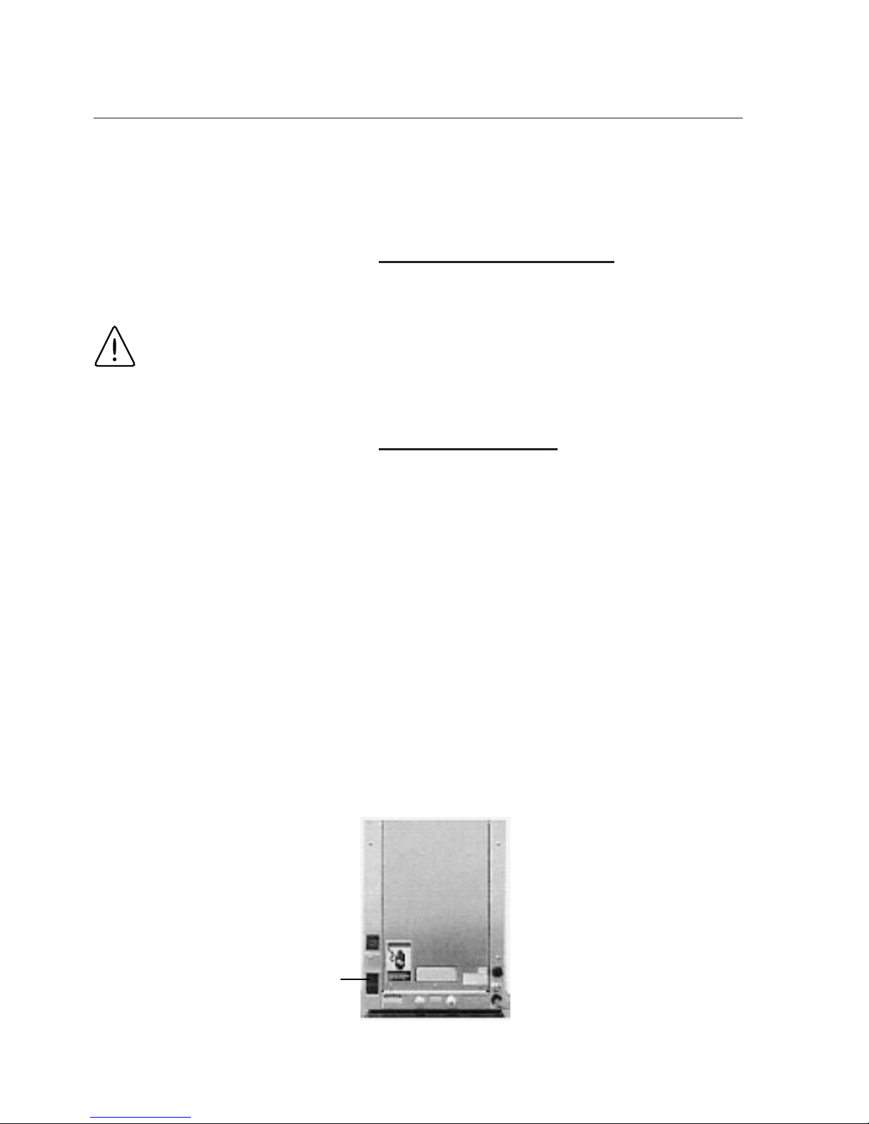
20
Electrical Connections
1. Plug power cord into the unit's power
entry module.
2. Connect your EASYpure RO to a properly
grounded outlet of correct voltage and
current handling capacity.
Membrane Flush
1. If not already done, disconnect the product water tubing from any EASYpure unit
connected to your EASYpure RO. Direct
the product water tubing to drain. If you
are feeding an accessory 30 Liter
Reservoir, disconnect the product water
tubing from the accessory 30 Liter
Reservoir. Direct the product water tubing
to drain.
2. Disconnect the pump interlock cord from
the other EASYpure unit.
3. Open the customer-supplied feed water
valve.
I
NSTALLATION
Power Entry
Module
Figure 8 Power Cord Attachment
Use a properly grounded
electrical outlet of correct
voltage and current handling
capacity.
Warning
Page 21
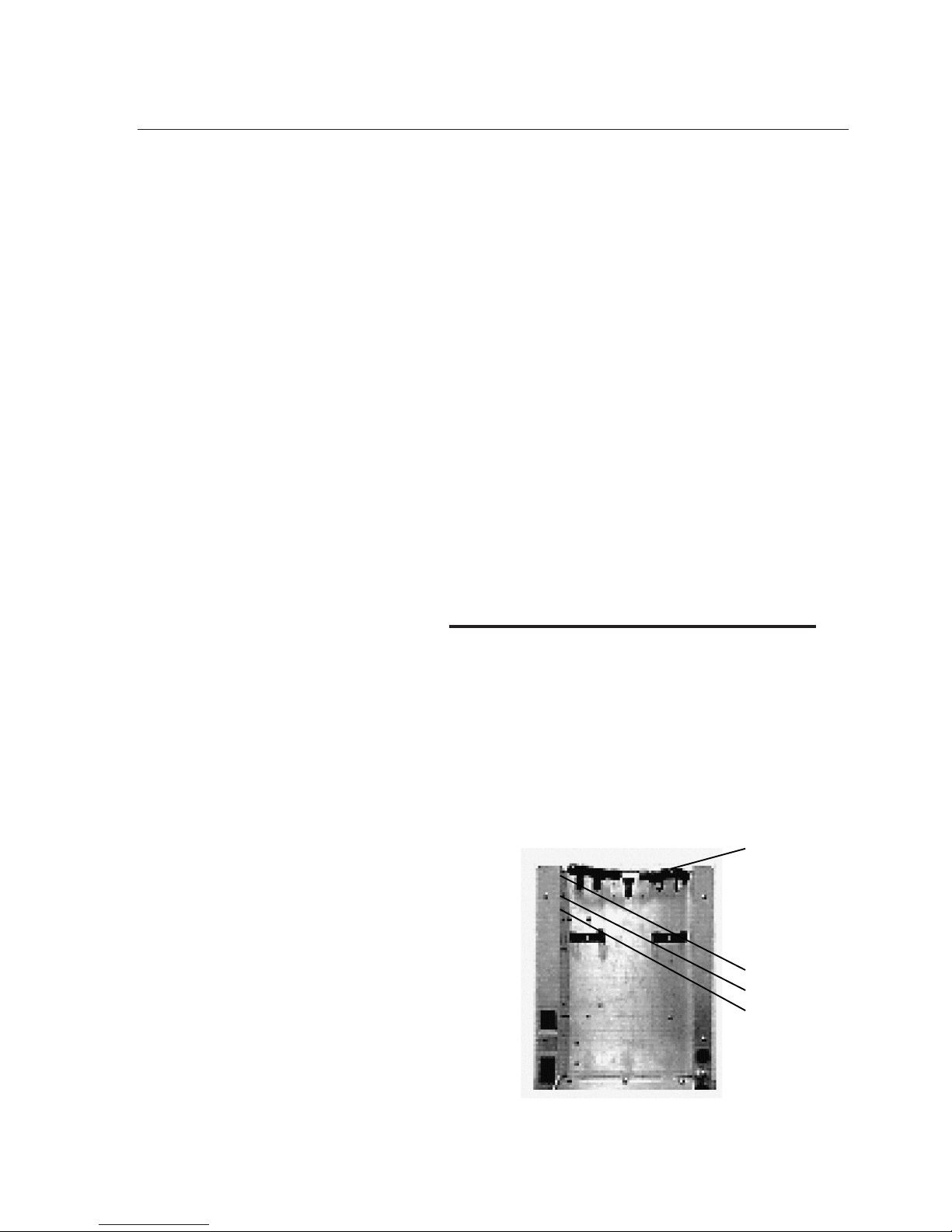
21
4. Turn the unit on by depressing the
ON/OFF switch on the power entry module in the rear of the EASYpure RO (see
Figure 8, page 19).
5. Allow the unit to operate for approximately
one hour, sending all water produced to
drain.
6. Turn unit power off. Reconnect the product water tubing to the other EASYpure
unit. Reconnect the product water tubing
to the accessory 30 Liter Reservoir.
Reconnect the pump interlock cord to the
other EASYpure unit.
Set "Replace Prefilter" Indicator
The extruded carbon prefilter both filters particulates and absorbs free chlorine out of your feedwater supply. After a certain point, the extruded carbon will become saturated with chlorine and will
cease to effectively protect your membrane from
the damaging effects of chlorine. The "Replace
Prefilter" Indicator alerts you when the prefilter
requires changing.
I
NSTALLATION
Switch Panel
Figure 9 Switch Panel Location
Membrane Reset
Membrane
Bypass
Tubing
Prefilter Reset
Page 22

22
To set the "Replace Prefilter" Indicator for your
feedwater supply:
1. Determine the free-chlorine level of your
feedwater (in ppm) using a commercially
available test kit.
2. Disconnect the unit from the power supply.
3. Pull the rear side of the door latch up and
toward the front of the unit until the front
of the door latch unhooks.
4. Lift the front of the door latch and open
door.
5. Locate the switch panel on the upper left
sidewall of the membrane compartment.
(See Figure 9 for location.)
6. The four rocker switches on the switch
panel are numbered from left to right as
you face the switch panel. Each switch
has two possible positions: 1) top pressed
in or 2) bottom pressed in. (See Figure
10.)
Set the switches for your free-chlorine level as
follows:
I
NSTALLATION
Page 23
23
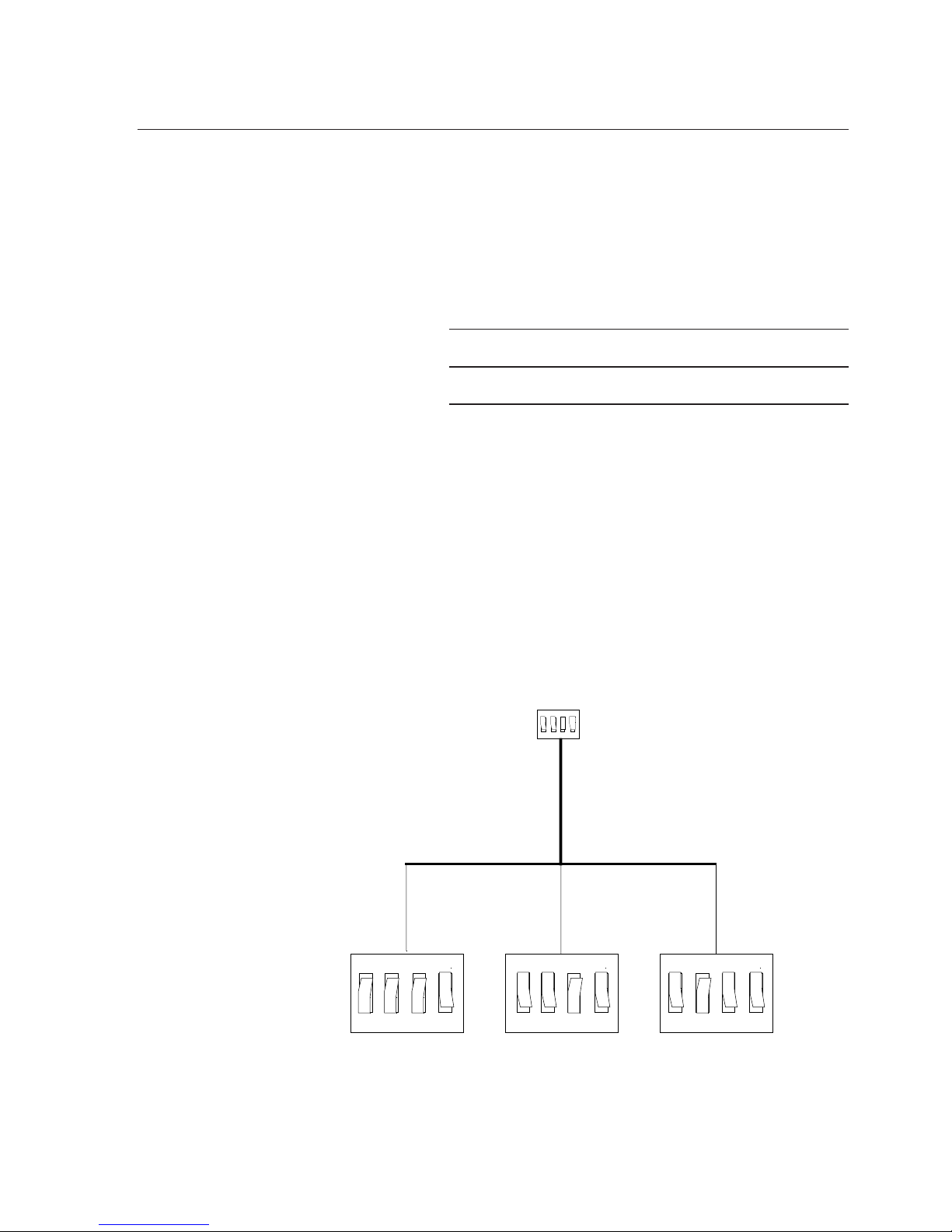
Free-Chlorine
Range (ppm) Switch 1 Switch 2 Switch 3 Switch 4
0.05-0.80 ppm bottom in bottom in bottom in top in
0.80-1.40 ppm* top in top in bottom in top in
More than 1.40 ppm top in bottom in top in top in
Close and latch the membrane access door. Your
EASYpure RO is now ready for operation.
I
NSTALLATION
* Factory set.
Figure 10 Switch Panel Settings
123
4
Free Chlorine
1.4 ppm - Max.
Free Chlorine
0.8 - 1.4 ppm
Free Chlorine
0.05 - 0.80 ppm
12341234123
4
Page 24

24
Your EASYpure RO was designed to operate automatically. The unit will automatically turn off when
the tank is full and will restart when the tank empties slightly. The unit will restart automatically for 5
minutes every 3 hours 55 minutes of inactivity to
flush the membrane during periods of non-use.
This flush water will automatically run to the drain.
Please ensure that the unit remains on — if you
need to de-energize the system for longer then 48
hours contact Barnstead|Thermolyne customer service. If water is not drawn from the tank for 72
hours, empty tank and refill with new RO water
before using.
Indicators
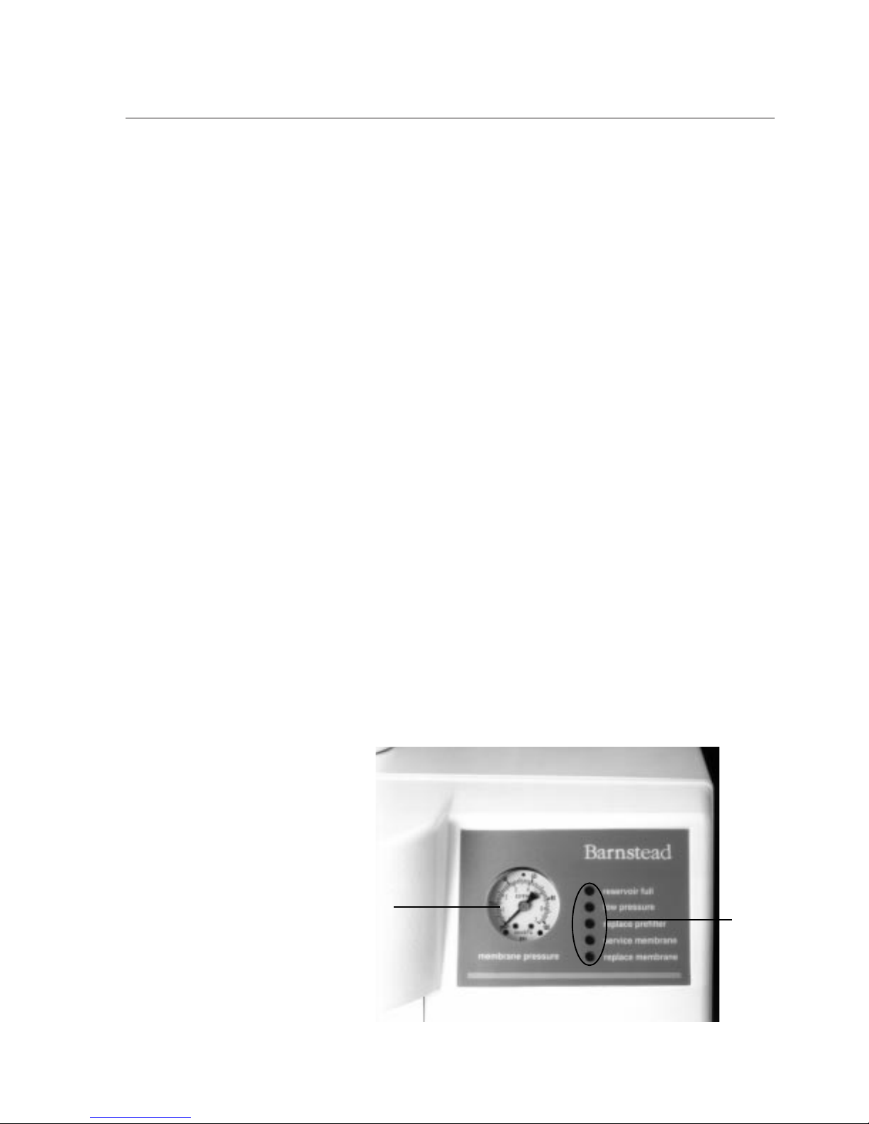
(See Figure 11, page 25.)
Pressure Gauge
On initial start-up, the pressure gauge will briefly
indicate the feedwater pressure. Once the pump
starts, the pressure gauge will indicate the pressure after the pump, which is the pressure on the
reverse osmosis membranes. During normal operation, this gauge should read 55-65 psi.
LED's
There are five indicator lights on the EASYpure RO
front panel. Their significance is as follows:
Indicator Lights
These lights alert you of the
operating status of the unit. If your attention is required to correct a problem or maintain the system,
it will be indicated on the display (periodically
check the panel to see if attention is required). A
listing of the various indicator lights and their
meanings follow:
Operation
Warning
Do not use in the presence of
flammable or combustible
materials; fire or explosion
may result. This device contains components which may
ignite such materials.
Page 25
25
1. Reservoir full: Your EASYpure RO is
equipped with a float switch that will deenergize the unit when the reservoir is
full. This light will illuminate, indicating
the unit is in a standby mode. When the
reservoir’s water level is lowered about
five inches, the unit will re-energize and
the light will turn off.
2. Low pressure: If the incoming water
pressure at the pump drops below 5
psig, a switch will de-energize the
pump. This switch senses the pressure
after the prefilter and before the pump.
The EASYpure RO system will try to
restart after it initially senses low pressure. If it senses low pressure the second time, it will switch the EASYpure
RO off and will illuminate the low pressure light. Once the fault is corrected,
the EASYpure RO must be manually
restarted. (Power down and power up).
3. Replace prefilter: The carbon used in
the extruded carbon cartridge has a
finite life. The function of this cartridge
is to remove particulates and chlorine
O
PERATION
Indicator
Lights
Figure 11 Display
Pressure Gauge
Page 26

26
from the feedwater. The "Replace
Prefilter" Indicator notifies you
when the prefilter requires changing. The frequency with which this
light will illuminate will vary depending on the feedwater free chlorine
level you have selected on the
switch panel on the inside rear left
side of the case. For proper operation and protection of your membrane, it is important that you accurately select your feedwater free
chlorine level on the switch panel.
4. Service membrane: If the percent
rejection rate of the membrane falls
below 65% the light will illuminate,
indicating membrane difficulty. In
most cases replacement of the
membranes is called for. Refer to
troubleshooting guide for further information. At times during operation
the light may illuminate. This may
be caused by feedwater variation or
extended periods of non-use. This
should correct itself within a short
time.
5. Replace membrane: Even under
optimal conditions, your EASYpure
RO reverse osmosis membranes
have a finite life span. This indicator illuminates when your membranes have reached the end of
their rated service life. Refer to
page 32 for the proper replacement
procedure.
O
PERATION
Page 27

27
Caring For Your EASYpure RO
With proper care, your EASYpure RO will give
you consistently pure water. To ensure continued good service, regularly perform the following procedures.
System Sanitization
The frequency of sanitizing depends on the
rate and amount of contamination buildup.
The membrane cartridges
must
be removed.
The EASYpure RO can easily be completely
sanitized by utilizing the sanitization cartridge
(Part Number D50245). To accomplish this, follow these step-by-step instructions:
1. Turn off the EASYpure RO. Turn off
an EASYpure unit or NANOpure fed
by the EASYpure RO. Depressurize
the EASYpure unit or NANOpure by
opening the drawoff valve (auxiliary
drawoff on NANOpure) and allowing
water to flow until no more exits the
unit. Disconnect the EASYpure unit or
NANOpure from the power supply.
2. Close the inlet valve on the
EASYpure unit. Disconnect from the
EASYpure RO the tubing attaching
the EASYpure RO to the EASYpure
unit. Disconnect this same tubing
from the EASYpure unit. Direct one
end of the tubing to drain. Reattach
the other end to the EASYpure RO.
Allow the tank to drain.
Maintenance
Warning
Disconnect from the power
supply prior to maintenance
and servicing.
Refer servicing to qualified
personnel.
Ensure all piping connections
are tight to avoid leakage of
chemicals.
Ensure adequate ventilation
when using chemicals for
cleaning.
Follow carefully the manufacturers’ safety instructions on
labels of chemical containers
and Material Safety Data
Sheets (M.S.D.S.).
Page 28

28
3. If you are feeding a NANOpure, remove
from the NANOpure the tubing from the
"T" on the accessory 30 Liter Reservoir.
Drain the accessory 30 Liter Reservoir by
opening the spigot.
4. Disconnect the quick disconnect insert(s)
and product water tubing attached to the
EASYpure RO.
5. Remove the pretreatment cartridge and
membrane cartridges.
6. Install the membrane bypass tubing on
the top membrane connectors.
7. Install the bottom bypass into the two
membrane inlets.
a. Wet the o-rings on the connectors of
the bypass tubing.
b. Insert the connectors into the two
membrane inlets. Ensure that the
metal clamps line up with the slots
located on the floor of the cabinet.
c. Rotate the connectors to lock the
metal clamps into position.
8. Install the sanitization cartridge in the pretreatment cartridge position.
9. Power up the EASYpure RO and allow the
water to move from the inlet line, through
the sanitization cartridge, and through the
rest of the system. The unit may turn off
as a result of the low pressure condition
once or twice during this step. If this
occurs, power down and power back up
again.
M
AINTENANCE
Page 29

29
10. Allow the system to operate normally until
the reservoir is full and the unit goes into
standby.
11. Allow the solution to sit in the system for
30-45 minutes.
12. Reconnect the quick disconnect insert(s)
and product water tubing removed in step
4. Direct the tubing to drain and drain the
storage reservoir. After the reservoir is
empty, disconnect the quick disconnect
insert(s) and product water tubing again.
13. Remove the top and bottom membrane
bypass tubing assemblies and retain them
for future use. Remove the sanitization
cartridge and discard it.
14. Install a new pretreatment cartridge.
Reinstall existing membrane cartridges if
they were operating properly.
15. Reset pretreatment timer. (See “Prefilter
Replacement.”)
16. Operate normally. Drain the first tankful of
water as described in step 12.
17. Reconnect the product water tubing to the
EASYpure unit. Reconnect the product
water tubing to the NANOpure. Reconnect
the EASYpure unit or NANOpure to the
power supply.
M
AINTENANCE
Note
Reinstalling your old membranes may reintroduce bacteria into your EASYpure RO
system.
Page 30
30
M
AINTENANCE
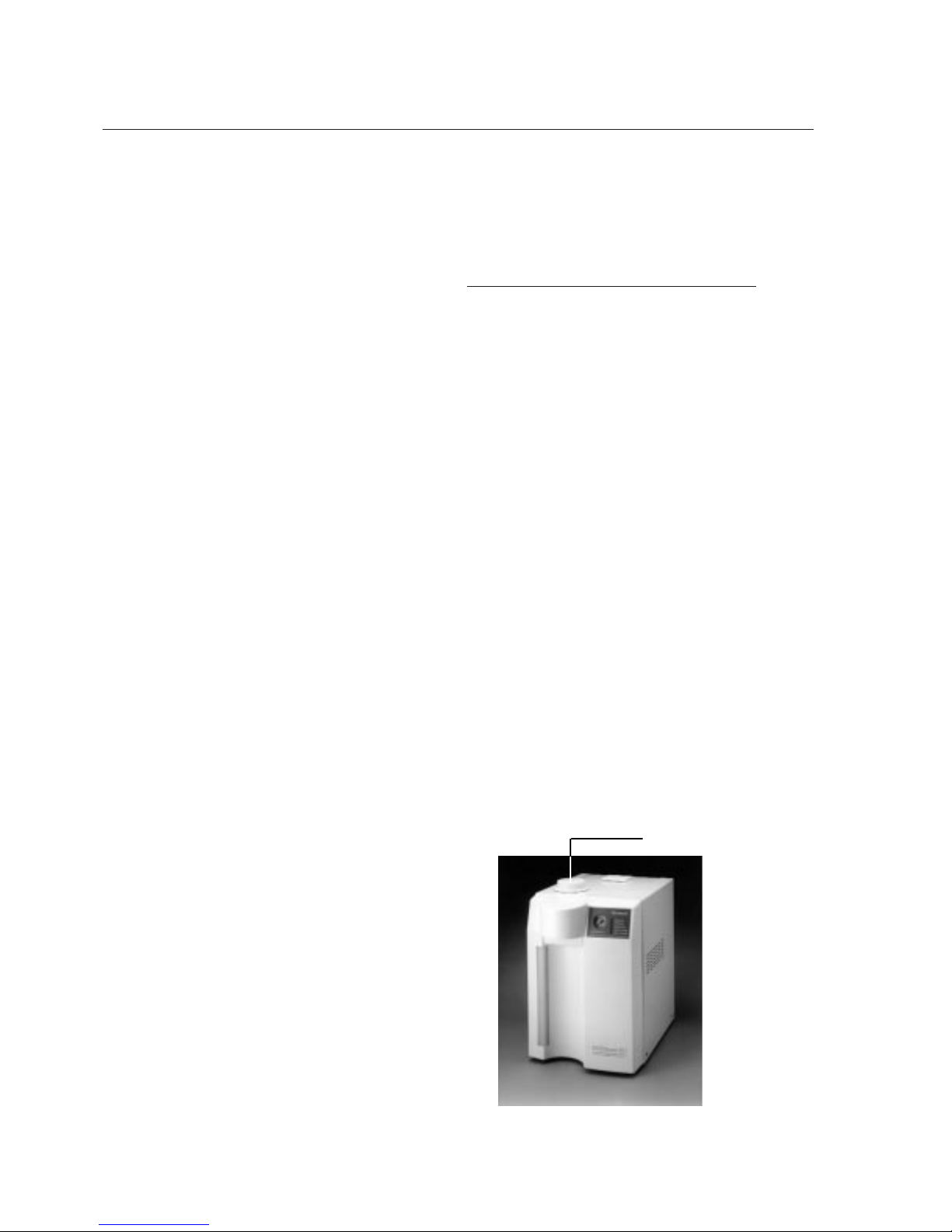
Ventgard®Filter Replacement
The materials in the Ventgard®have a limited capacity. The Ventgard®should be
replaced every 90 days or after 1,000 gallons have been drawn from the storage tank.
A Ventgard®may be stored in a cool, dry
place almost indefinitely, provided the plastic
bag has not been opened. Take the old
Ventgard®off the top of the EASYpure RO
and install a fresh one. (See Figure 12 for
location.)
General Cleaning Instructions
Wipe exterior surfaces with lightly dampened
cloth containing mild soap solution.
Ventgard®
Figure 12 Ventgard®Location
Page 31

31
Normal Unit Operation
Below is a brief description of the normal automatic
operation of the EASYpure RO. If the unit does not
operate as described below, refer to the Troubleshooting Guide.
When you activate the power switch, the follow-
ing events will occur:
1. All LEDs light momentarily to indicate that
they work.
2. After approximately 5 seconds, the automatic solenoid valves are energized. The
inlet valve opens, supplying the EASYpure
RO with water. The flush valve also
opens, diverting virtually all the water to
drain.
3. After approximately 20 seconds, the pump
energizes. The majority of the water produced goes to drain.
4. 10 seconds after the pump energizes, the
pressure switch begins monitoring the
incoming water pressure.
5. After 3 minutes, the flush solenoid valve
closes and the EASYpure RO begins making product water and sending it to the
storage reservoir.
6. The unit begins to monitor membrane performance and the storage reservoir floats
begin to monitor tank levels 5 seconds
after the flush solenoid valve closes.
During operation, the storage reservoir
floats will: 1) switch the EASYpure RO into
standby mode (pump off) when the storage reservoir is full, 2) switch the
EASYpure RO back into water production
mode (pump on) when the reservoir level
Service and Repair
Warning
Disconnect from the power
supply prior to maintenance
and servicing.
Refer servicing to qualified
personnel.
Ensure all piping connections
are tight to avoid leakage of
chemicals.
Ensure adequate ventilation
when using chemicals for
cleaning.
Follow carefully the manufacturers’ safety instructions on
labels of chemical containers
and Material Safety Data
Sheets (M.S.D.S.).
Page 32

32
drops approximately five inches, and 3)
switch off any EASYpure unit connected to
the EASYpure RO when the water level in
the EASYpure RO's storage reservoir is
too low to ensure an adequate water supply to the other EASYpure unit (this
requires the pump interlock cord to be
installed).
7. The microprocessor tracks operating time
and at pre-selected intervals illuminates
the “replace filter” light, signifying that the
carbon cartridge should be replaced.
8. When the reservoir is full and the
EASYpure RO is in standby mode, a clock
is activated which energizes the
EASYpure RO for five minutes every three
hours and fifty-five minutes. This ensures
that water will not stagnate on the membrane surface. The majority of the water
produced during this five-minute cycle will
divert to the drain.
S
ERVICE AND REPAIR
Page 33
33
Fuse Replacement
1. Disconnect the EASYpure RO from its
power source. Remove the outer cover.
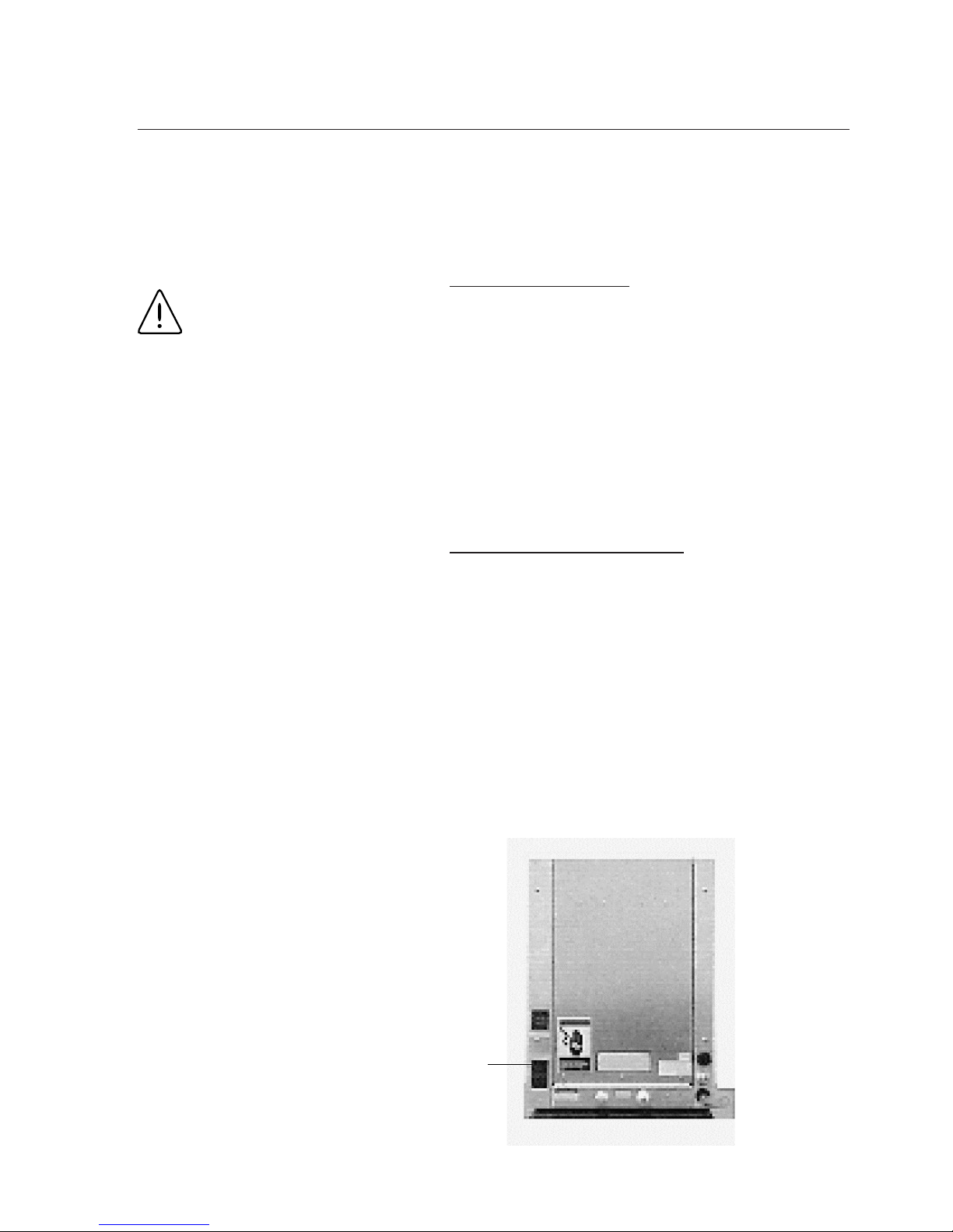
2. Locate the fuse holder, part of the power
entry module (see Figure 13 for location),
and remove.
3. Remove the burned out fuse(s) and
replace with one(s) of equal size and rating.
Membrane Replacement
A variety of factors will determine the service life of
your EASYpure RO membranes. With proper maintenance, the membranes should last approximately
one year for normal usage.
When either the "Service Membrane" or the
"Replace Membrane" Indicator lights, use the following procedure to replace the membranes:
1. Disconnect the EASYpure RO from its
power source.
2. Remove the membranes and discard.
S
ERVICE AND REPAIR
Fuse Holder
Location
Figure 13 Fuse Holder Location
Warning
Replace fuses with those of
the same type and rating.
Page 34

34
3. Install and flush new membranes
using the procedure for membrane
installation and flush listed under
"Membrane Installation."
4. After you replace the membranes,
press the "Replace Membrane"
Indicator reset button, located directly below the "Replace Prefilter"
Indicator reset button, which is in
turn directly below the switch panel
on the upper left sidewall of the
membrane compartment. (See
Figure 9, page 21, for location.)
Prefilter Replacement
It is impossible to exactly predict prefilter life
in the EASYpure RO. Due to varying amounts
of particulates and chlorine in feedwater, life
of the prefilter will vary. Replace the prefilter
when decreased water flow or repeated "Low
Pressure" shutdowns indicate that particulates have clogged the filter or when the
"Replace Prefilter" Indicator lights, indicating
that the prefilter has ceased to reliably
remove chlorine from the feedwater.
1. Disconnect the EASYpure RO from
its power source.
2. To replace the prefilter, remove the
old prefilter, then follow the procedures in "Prefilter Installation" to
install a new one.
3. After you replace the prefilter, press
the "Replace Prefilter" Indicator reset
button, located directly below the
switch panel on the upper left sidewall of the membrane compartment.
(See Figure 9, page 21, for location.)
Note
This reset button is a two
position button; it will be
either up or down. Press it
only once, to change its
position. (I.e. if it was up
before you changed the prefilter, you should press it
down after you change the
prefilter. If it was down
before you changed the prefilter, you should press it
after you change the prefilter
to allow it to come up.)
This reset button is a two
position button; it will be
either up or down. Press it
only once, to change its
position. (I.e. if it was up
before you changed the
membranes, you should
press it down after you
change the membranes. If it
was down before you
changed the membranes,
you should press it after you
change the membranes to
allow it to come up.)
Note
S
ERVICE AND REPAIR
Page 35

35
This section contains parts list information for the EASYpure RO Reverse Osmosis
System. When ordering spare parts, specify part number (Cat. No.) and quantity desired.
Also supply part number and serial number (located on the unit). When ordering electrical
parts, provide voltage and frequency information.
Recommended Spares
Consumables
Consumable parts are those required to support the day-to-day operation
of this equipment. Barnstead|Thermolyne establishes two types of consumables; those
items that must be periodically replaced to maintain performance (filters, resin cartridges,
etc.) and other items of limited service life (indicator lights, fuses, etc.) that you can expect
to replace on a more or less random basis. Wherever possible, Barnstead|Thermolyne
recommends the frequency of replacement or provides information on service life
expectancy. You thus may calculate a replacement schedule based on your usage pattern.
The replacement of consumable parts is discussed in the Maintenance section of this
manual to assist you in accomplishing your own service.
CONSUMABLES
Description Cat. No. Quantity
Pretreatment cartridge D50246 3
Ventgard®Filter Element (EASYpure RO) CV742X5A 2
Fuse 120V & 100V 04455 2
Fuse 230V (Fuse Type (T) 2a 250V) 5120-0025 2
Fuse 240V FZX37 2
Sanitization Cartridge D50245 1
Parts List
Page 36

36
Safety Stock
For critical applications where performance with MINIMUM downtime is required, Barnstead|Thermolyne recommends that you
maintain a local stock of those parts listed under “General Maintenance”
and “Safety Stock.” In the event of component failure, this safety stock
can be drawn upon by you or Barnstead|Thermolyne technicians, thereby, avoiding unnecessary delays in delivery of replacement parts.
SAFETY STOCK
Description Cat. No. Quantity
Pump 100 volt low pressure PU742X3A 1
Pump 120 volt PU742X1A 1
Pump 120 volt low pressure PU742X3A 1
Pump 230 volt PU742X2A 1
Pump 230 volt low pressure PU742X4A 1
Pump 240 volt PU742X2A 1
Pump 240 volt low pressure PU742X4A 1
Main PC Board PC742X2A 1
Pressure Switch 01407 1
Solenoid Valve 100 & 120 Volt RY631X1A 1
Solenoid Valve 230 Volt RY631X3A 1
Solenoid Valve 240 Volt RY631X3A 1
Pressure Regulating Valve* 02280 1
Reject Flow Restrictive orifice PMX101 1
Membrane D7425 2
* Not included on low pressure units, Model numbers D7423, D7428, D7429and
D7429-33.
PARTS LIST
Page 37

37
Please refer to the Specification Plate for the
complete model number, serial number, and series number when requesting service, replacement parts or in any correspondence concerning
this unit.
All parts listed herein may be ordered from the
Barnstead|Thermolyne dealer from whom you
purchased this unit or can be obtained promptly
from the factory. When service or replacement
parts are needed we ask that you check first with
your dealer. If the dealer cannot handle your
request, then contact our Customer Service Department at 319-556-2241 or 800-553-0039.
Prior to returning any materials to
Barnstead|Thermolyne Corp., please contact
our Customer Service Department for a “Return
Goods Authorization” number (RGA). Material returned without a RGA number will be refused.
Ordering Procedures
Page 38

38
Troubleshooting
Problem Possible Causes Solutions
EASYpure RO
completely inactive
(Controls not operating)
No electrical power to
EASYpure RO
Ensure EASYpure RO
power cord is installed
and connected to live
power.
Blown fuses Check/Replace fuses.
Refer to
Fuse
Replacement
for
procedure.
No water flowing (low
pressure indicator light
illuminated)
Feedwater supply valve
closed
Open feedwater supply
valve
Prefilter plugged Replace prefilter
Solenoid valve not open Replace solenoid valve
Feed pressure below
specification
Increase pressure
Illumination of service
membrane light.
Decrease in % rejection
Improperly installed
membrane
Insure membrane is
installed properly
Fouled membrane Replace membrane
Decrease in system
productivity
Decrease in water
temperature
If decline in flowrate is
unacceptable install
feedwater temperature
valve to elevate water
temperature
Membrane fouled Replace membrane
Low incoming water
pressure
Ensure prefilter is not
blocked - Increase
incoming water pressure
Low membrane
operating pressure
Increase operating
pressure
Page 39
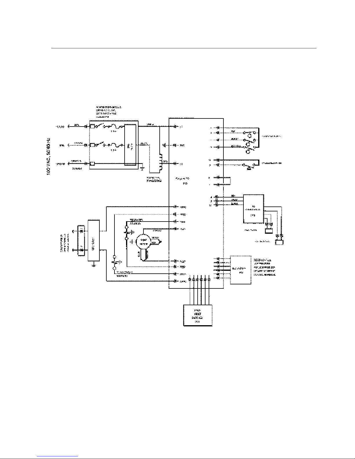
39
Wiring Diagrams
Figure 14 Wiring Diagram 100 Volt
Page 40
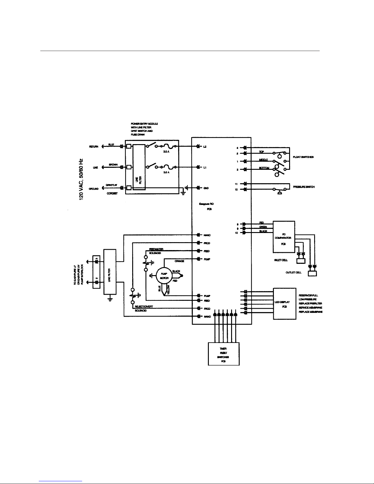
40
W
IRING DIAGRAMS
Figure 15 Wiring Diagram 120 Volt
Page 41
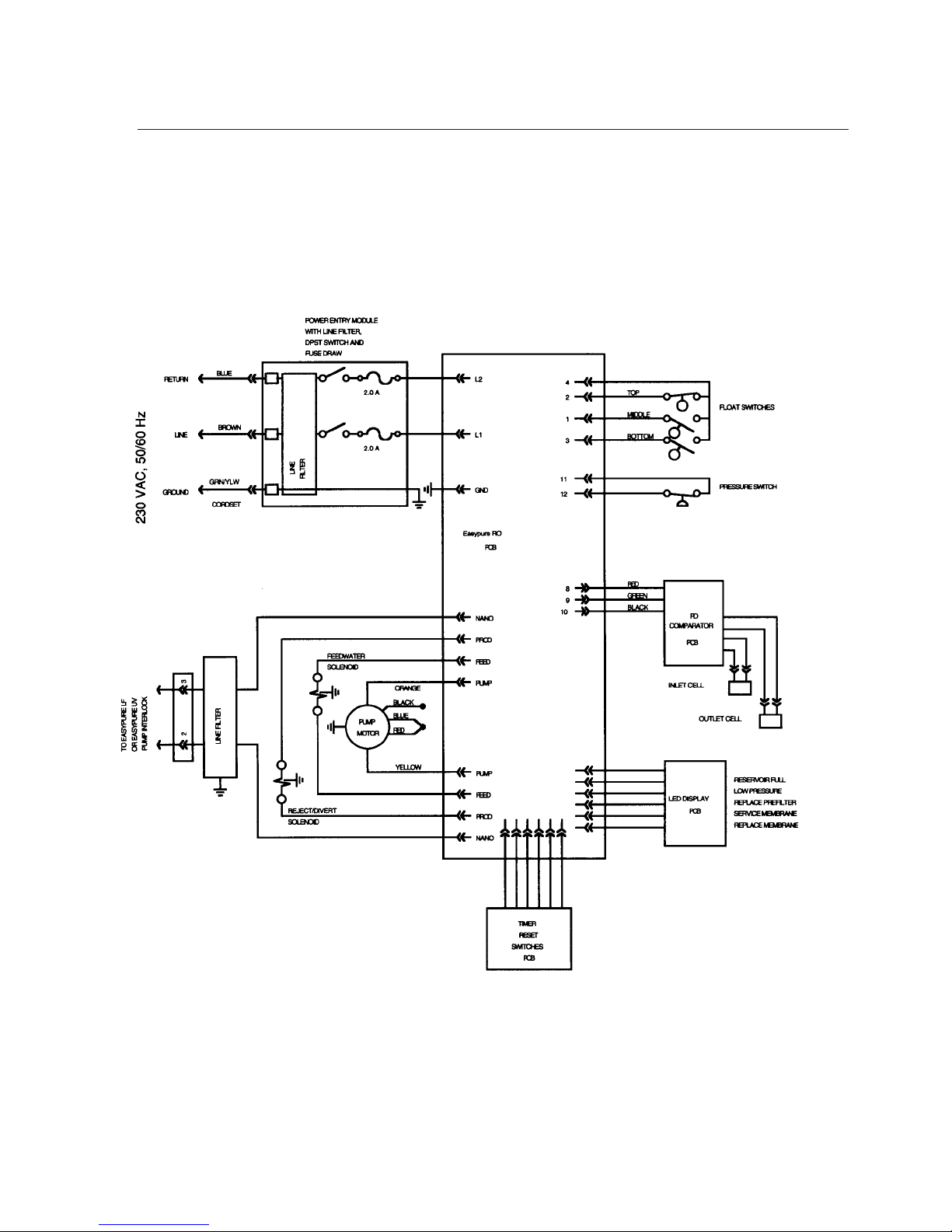
41
W
IRING DIAGRAMS
Figure 16 Wiring Diagram 230 Volts
Page 42
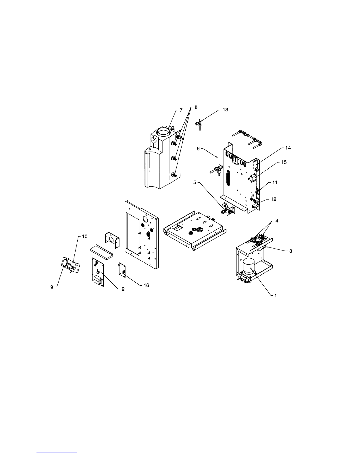
42
EASYpure RO Exploded View
Page 43

43
Exploded View Key
Key Part # Description
1. PU742X1A Pump 120 Volt
PU742X2A Pump 230 Volt
PU742X2A Pump 240 Volt
PU742X3A Pump 100 Volt & 120 Volt low pressure
PU742X4A Pump 230 Volt low pressure
PU742X4A Pump 240 Volt low pressure
2. PC742X2A Main PC Board
3. 01407 Pressure Switch
4. RY631X1A Solenoid Valve 100/120 Volt
RY631X3A Solenoid Valve 230 Volt
RY631X3A Solenoid Valve 240 Volt
5. 02280 Pressure Regulating Valve*
6. PMX101 Reject Flow Regulating Orifice (on side of rear case)
7. PM703X7A Overflow Valve
8. SW742X1A Float Switch, Reservoir
9. MEX172 Pressure Gauge
10. PC682X4A PC Board
11. CE742X1A Interlock Receptacle
12. CEX183 Power Entry Module
13. E631X1A Cell Assembly
14. PC742X1A PC Board
15. CAX44 Powerline Filter
16. PC631X3A PC Board
* Not included on low pressure units, Model numbers D7423, D7428, D7429 and D7429-33.
Page 44

44
One Year Limited Warranty
Barnstead|Thermolyne Corporation warrants that if a product manufactured by
Barnstead|Thermolyne and sold by it within the continental United States or Canada
proves to be defective in material or construction, it will provide you, without charge, for a
period of ninety (90) days, the labor, and a period of one (1) year, the parts, necessary to
remedy any such defect. Outside the continental United States and Canada, the warranty
provides, for one (1) year, the parts necessary to remedy any such defect. The warranty
period shall commence either six (6) months following the date the product is sold by
Barnstead|Thermolyne or on the date it is purchased by the original retail consumer,
whichever date occurs first.
All warranty inspections and repairs must be performed by and parts obtained from
an authorized Barnstead|Thermolyne dealer or Barnstead|Thermolyne (at its own dis-
cretion). Heating elements, however, because of their susceptibility to overheating and contamination, must be returned to our factory, and if, upon inspection, it is concluded that failure is not due to excessive high temperature or contamination, warranty replacement will be
provided by Barnstead|Thermolyne. The name of the authorized Barnstead|Thermolyne
dealer nearest you may be obtained by calling 1-800-446-6060 or writing to:
Barnstead|Thermolyne
P.O. Box 797
2555 Kerper Boulevard
Dubuque, IA 52004-0797
USA
FAX: (319) 589-0516
E-Mail: [email protected]
Barnstead|Thermolyne’s sole obligation with respect to its product shall be to repair
or replace the product. Under no circumstances shall it be liable for incidental or consequential damage.
THE WARRANTY STATED HEREIN IS THE SOLE WARRANTYAPPLICABLE TO
Barnstead|Thermolyne PRODUCTS. Barnstead|Thermolyne EXPRESSLY DISCLAIMS
ANY AND ALL OTHER WARRANTIES, EXPRESSED OR IMPLIED, INCLUDING WARRANTIES OF MERCHANTABILITY OR FITNESS FOR USE.
Barnstead Thermolyne
2555 Kerper Blvd.
P.O. Box 797
Dubuque, IA 52004-0797 USA
PHONE: 319-556-2241 • 800-553-0039
FAX: 319-589-0516
E-Mail: [email protected]
a subsidiary of
 Loading...