

Barnstead Harvey MC8, MC10 User manual

HARVEY
®
Service Manual
Models MC8 &
MC10
Steam Sterilizer
LT1203X2 • 2/16/02
y
B
I
Barnstead
Harve

2
Table of Contents
Safety Information ..............................................................................................................................................4
Alert Signals........................................................................................................................................................4
General Specifications ........................................................................................................................................5
General Information ............................................................................................................................................6
Controls ON/OFF..............................................................................................................................................7
Cycle Select Switches ......................................................................................................................................7
Cycle Start/Stop................................................................................................................................................7
Programming Switches ....................................................................................................................................8
Display Window ................................................................................................................................................8
Cycle Phase Indicators ....................................................................................................................................8
Principles of Operation ........................................................................................................ ................................9
Cycle Description..............................................................................................................................................9
Controls Description........................................................................................................................................11
Trouble Analysis................................................................................................................................................15
Fuse Replacement..........................................................................................................................................15
Diagnostic Messages......................................................................................................................................15
Diagnostics Mode............................................................................................................................................19
Testing for Leaks .............................................................................................................. ..............................19
Power Supply Circuits ....................................................................................................................................20
Heater Control Unit ........................................................................................................................................22
Solenoid Control Circuits ................................................................................................................................24
Component Check Procedures ......................................................................................................................25
Service Data................................................................................................................... ...................................29
LED Indicators ................................................................................................................................................40
Test Points ......................................................................................................................................................40
Adjustments ....................................................................................................................................................42
LED Indicators ................................................................................................................................................43
Switch Panel Functions ..................................................................................................................................43
Setup and Adjustments ....................................................................................................................................47
Voltage Conversions ......................................................................................................................................47
Software Configuration....................................................................................................................................48
Unit Calibration................................................................................................................................................54
Unit Verification ..............................................................................................................................................57
Control PC Board Adjustments ......................................................................................................................60
Display Contrast Adjustment ..........................................................................................................................61
Repair and Replacement ..................................................................................................................................62
Cabinet Removal Control Panel......................................................................................................................62
Power I/O PC board............................................................................................................. ...........................63
Control PC Board ............................................................................................................... .............................63
Control Panel ..................................................................................................................................................64
Transformer PC Board (MC10) ......................................................................................................................65
Pressure Transducer ......................................................................................................................................65
Temperature Probe ........................................................................................................................................66
Thermal Cut-Off Switch ..................................................................................................................................66
Heater ............................................................................................................................................................67
Solenoid Valves ............................................................................................................................................67

3
TABLE OF CONTENTS
Chamber Door ................................................................................................................................................68
Door Handle and Latch Replacement ............................................................................................................68
Door Cover Replacement ..............................................................................................................................69
Appendix ..........................................................................................................................................................70
4
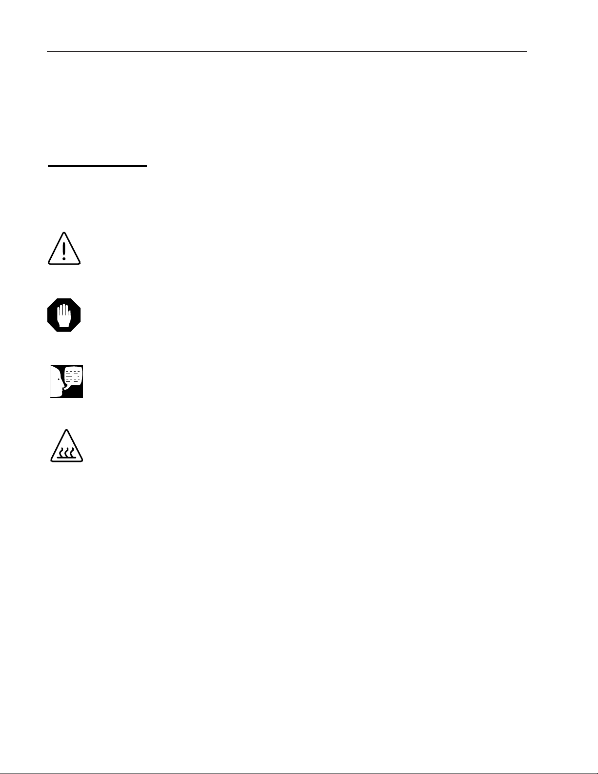
Safety Information
These symbols with related notes appear
throughout this manual.
Hot Surface
Hot surfaces alert you to a
possibility of personal injury if you
come in contact with a surface
during use or for a period of time
after use.
Caution
Cautions alert you to a possibility
of damage to the equipment.
Warning
Warnings alert you to a possibility
of personal injury.
Note
Notes alert you to pertinent facts
and conditions.
Alert Signals
NOTE:
This equipment has been tested and found to comply with the limits for a Class Adigital
device, pursuant to Part 15 of the FCC rules. These limits are designed to provide reasonable protection against harmful interference when the equipment is operated in a commercial environment. This equipment generates, uses and can rediate radiofrequency energy
and, if not installed and used in accordance with the instruction manual, may cause harmful
interference to radio communications. Operation of this equipment in a residential area is
likely to cause harmful interference in which case the user will be required to correct the
interference at his own expense.

5
General Specifications
Cabinet Size 13-1/2” W x 16” H x 22” L 16” W x 18” H x 23” L
(330 mm W x 406mm H x 559mm L) (406mm W x 457mm H x 584mm L)
Chamber Size 8” diameter x 14-1/2” usable depth 10” diameter x 15-1/2” usable depth
(203mm diameter x 368mm) (254mm diameter x 393mm)
Tray Sizes Two 14” x 6-1/4” x 7/8” One 15-1/4” x 9” x 1-1/4”
(356mm x 135mm x 22mm) (387mm x 228mm x 32mm)
Shipping Weight 72 lbs (33 kg) 92 lbs (42 kg)
Heater Wattage 1350 Watts 1425 Watts
Electrical Rating 115 VAC, 50/60 Hz, 12 Amps or 115 Vac, 50-60 Hz, 12 Amps or
230 VAC, 50/60 Hz, 6 Amps 230 VAC, 50/60 Hz, 6 Amps
(See Note) (See Note)
Reservoir Capacity 3000 ml (approx. 3 quarts) 4000 ml (approx. 4 quarts)
Maximum Rated 45 psi (310 kPa) 45 psi (310 kPa)
Operating Pressure
Environmental Conditions
Operation 10° to 40°C (50° to 104°F) 10° to 40°C (50° to 104°F)
30% to 70% relative humidity, 30% to 70% relative humidity,
non-condensing non-condensing
Storage and Transport -20° to 60°C (-4° to 140°F) -20° to 60°C (-4° to 140°F)
10% to 100% relative humidity 10% to 100% relative humidity
Printer (Optional)
Electrical Rating 9 VAC; 1 WATT (idle), 9 VAC; 1 Watt (idle),
10 Watts (running) 10 Watts (running)
Non-Recirculating Water Accessory (Optional)
Size 6-3/4” W x 13-1/2” H 15-1/4” L 6-3/4” W x 13-1/2” H 15-1/4” L
(171mm W x 343mm H x 387mm L) (171mm W x 343mm H x 387mm L)
Capacity 11.36 L (approx. 3 gallons) 11.36 L (approx. 3 gallons)
MC8 MC10
6
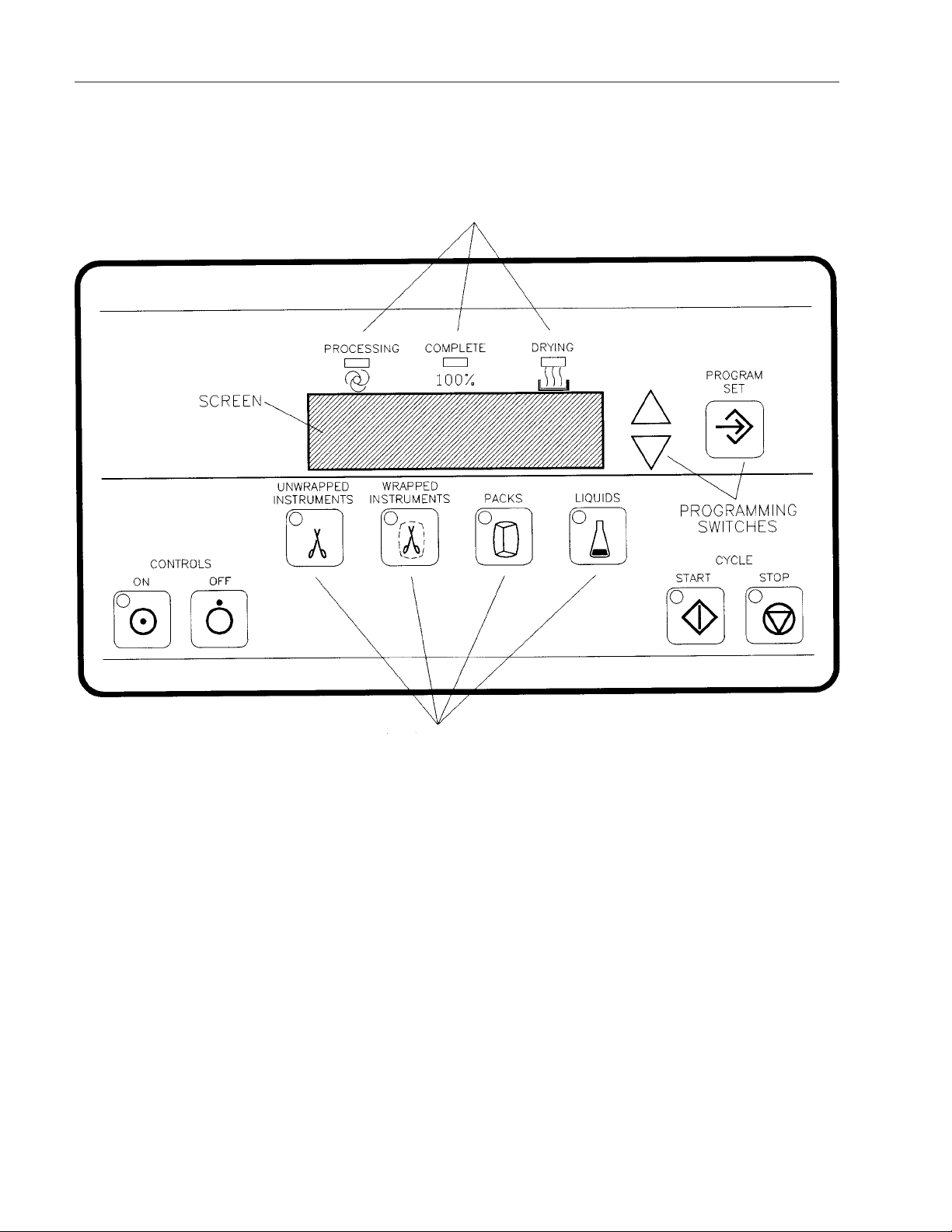
General Information
Figure 1
Control Panel
Cycle Phase Indicators
Cycle Select Switches
7
Controls ON/OFF
• CONTROLS ON: Turns ON the
Control Panel.
• CONTROLS OFF: Turns OFF the
Control Panel.
Cycle Select Switches
• UNWRAPPED INSTRUMENTS:
Selects cycle for unwrapped
instruments (3 minute exposure at
135°C).
• WRAPPED INSTRUMENTS: Selects
cycle for wrapped instruments ( 5
minute exposure at 135°C).
•PACKS: Selects cycle for linen packs
(30 minutes exposure at 121°C).
• LIQUIDS: Selects cycle for liquids and
glassware (30 minute exposure at
121°C, slow exhaust).
Cycle Start/Stop
• CYCLE START: Starts the selected
processing cycle.
• CYCLE STOP: Stops the cycle in
progress.
G
ENERAL
INFORMATION
Note
When the power cord is plugged
in and the controls are OFF, the
Control Panel will display the
time.
Note
Cycle times are adjustable from
minimum allowable exposure
time up to 99 minutes.

8
Programming Switches
• PROGRAM/SET: Used to set clock/calendar, select cycle parameters in memory.
•UPAND DOWN ARROWS: Used with
the PROGRAM/SET switch to select
operating procedures.
Display Window
A two-line LCD displays cycle parameters, counts
down exposure and drying times, and displays
messages.
Cycle Phase Indicators
• PROCESSING: Indicates load is being
processed at selected time and
temperature.
• COMPLETE: Indicates processing cycle
is complete.
•DRYING: Indicates load is drying for
selected time.
G
ENERAL I
NFORMATION
9
Cycle Description
Controls ON (Standby)
The vent valve is open when the unit is in
standby mode. The heater is turned on to warm
up the chamber.
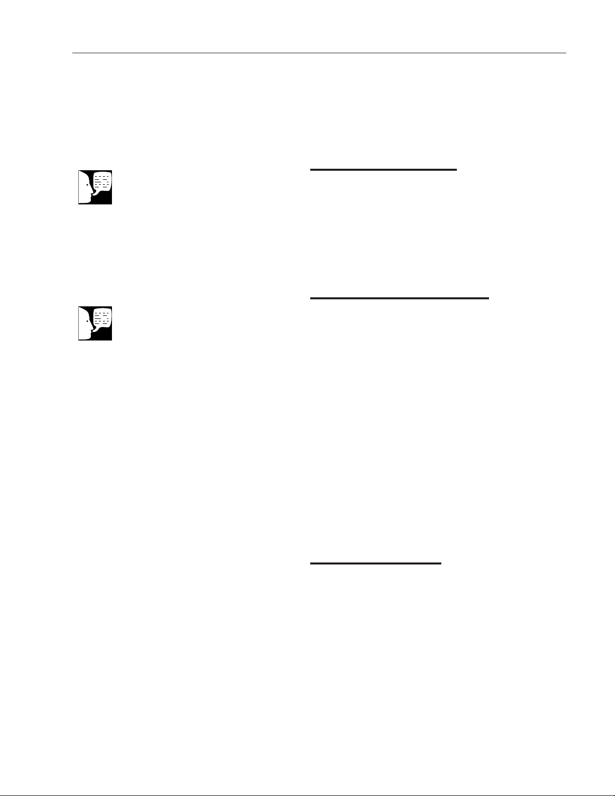
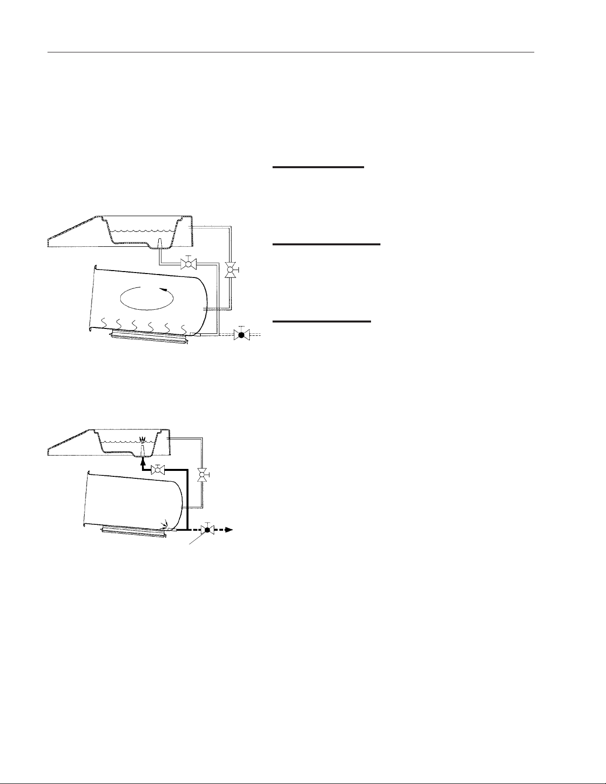
Fill Phase
When CYCLE START is pressed, a 30 second
delay begins, during which time the chamber
temperature is allowed to stabilize. For the
duration of this delay the display will read
“Cooling Chamber” and the current chamber
temperature. The sterilizer will wait up to 60
minutes for the chamber to drop below 70%
before the Fill Phase. When the chamber has
cooled, there is a 15 second delay and then
the fill valve is open for timed period. Water
from the reservoir enters the chamber.
Air Removal Phase
The fill valve is closed and the heater is turned
on. The water boils, producing pressure that
forces air out of the chamber through the vent
valve.
Principles of Operation
Figure 2
Fill Phase
Figure 3
Air Removal Phase
Note
For detailed cycle information,
refer to the cycle phase diagrams
in the Service Data section.
Reservoir
Fill
Vent
Reservoir
Heater
Air
Vent
Fill
10
Heatup Phase
The vent valve is closed and the chamber
pressure increases until the exposure set point is
reached.
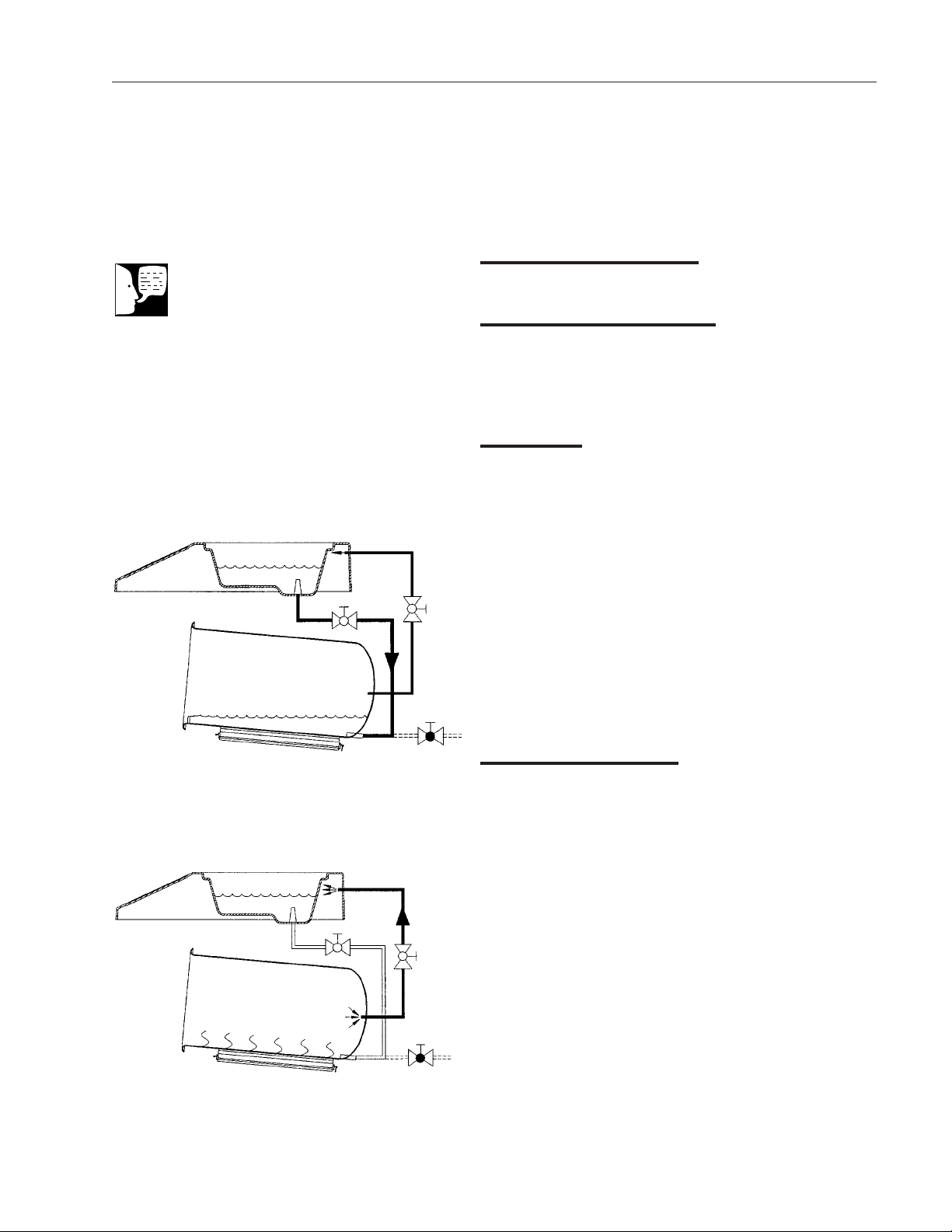
Exposure Phase
The exposure set point is maintained for a timed
period. The heater is controlled to maintain the
chamber temperature and pressure.
Exhaust Phase
Dry Goods (Recirculating Unit)
The heater is turned off and the fill (exhaust)
valve is opened. Steam exhausts back into the
reservoir. Near the end of the phase, the fill valve
is closed and the vent valve is opened to relieve
the remaining pressure.
Dry Goods (Non-Recirculating Unit)
The heater is turned off and the drain valve is
opened. Steam exhausts into the external
collection bottle. Near the end of the phase, the
drain valve is closed and the vent valve is
opened to relieve the remaining pressure.
Liquids (Recirculating Unit)
The heater is turned off and the fill (exhaust)
valve is opened and closed in small increments
to slowly bleed off the chamber pressure. Steam
exhausts back into the reservoir. Near the end of
the phase, the fill valve is closed and the vent is
opened to relieve the remaining pressure.
Liquids (Non-Recirculating Unit)
The heater is turned off and the drain valve is
opened and closed in small increments to slowly
bleed off the chamber pressure. Steam exhausts
into the external collection bottle. Near the end of
Figure 5
Exhaust Phase
PRINCIPLES OF
OPERA TION
Reservoir
Steam
Recirculating Drain
To
Collection
Bottle
Non-Recirculating
Drain
Figure 4
Exposure Phase
Fill
Heater
Reservoir
Steam

11
the phase, the drain valve is closed and the
vent valve is opened to relieve the remaining
pressure.
Drying Phase (Optional)
Open Door
The operator opens the door and leaves it ajar.
The heater is controlled to provide a heated
chamber for drying goods. The vent valve remains open.
Closed Door
The drying phase, if selected, starts
automatically at the end of the cycle. The heater is controlled to provide a heated chamber
for drying goods. The vent valve remains open.
Controls Description
The electronic controls include the following
assemblies:
• Power I/O PC Board 2A
• Control PC Board 3A
• Control Panel 4A
• Printer 5A (optional)
•Transformer PC Board 6A (optional
MC10 printer)
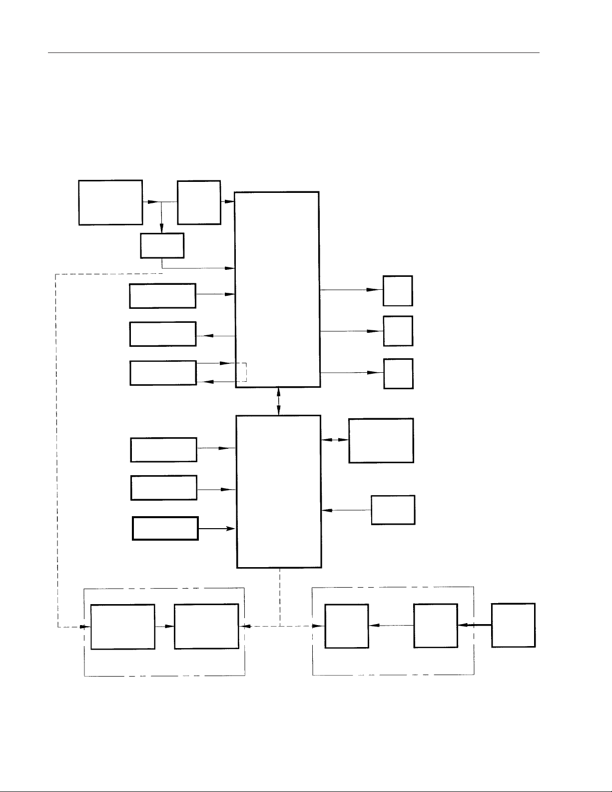
Power Input
The customer supply input (115 or 230 VAC) is
routed to the EMI filter, Power I/O PC Board,
and Transformer PC Board. The filtered input is
applied to the Power I/O Board, which produces the required operating voltages for the
controls.
P
RINCIPLES OF
OPERA TION

12
Power I/O Board
The Power I/O PC Board produces +24 VDC for
the solenoid valves and +5 VDC for the control
circuits. The unfiltered supply voltage is routed to
the heater circuit.
The Power I/O PC Board communicates with the
Control PC Board via a serial data interface. In
response to commands from the Control PC
Board, the Power I/O PC Board controls solenoid
valves 1SOL through 3SOL and heater
1HTR/2HTR. The solenoid valves are activated
by the solenoid driver on the Power I/O PC
Board. The heater is activated by solid-state
relay 1SSR, mounted on the chassis.
If an over temperature condition should occur,
thermal switch 2SW will open to remove power
from the heaters.
Control PC Board
The Control PC Board contains a microprocessor
that controls the sterilization cycle. The
microprocessor monitors temperature, pressure
and switch inputs, and controls the solenoid
valves and heaters via the Power I/O PC Board.
The input from temperature sensor 1RT is an
analog voltage that is applied to a conditioning
circuit which produces coarse and fine control
voltages. These voltages are applied to the
microprocessor for precise control of the chamber temperature.
The pressure input from 1PT is an analog voltage that is applied directly to the microprocessor.
The amplitude of the voltage is proportional to
the pressure.
P
RINCIPLES OF
OPERA TION

13
The Control PC Board communicates with the
printer over a serial data interface.
Control Panel
The control panel is a membrane switch panel
connected to the Control PC Board by a ribbon
cable.
Printer
The MC8 printer connects to the printer receptacle on the back of the sterilizer. Power for the
printer is provided by a transformer-type wall
plug.
The MC10 printer is mounted next to the
Control Panel.
Transformer PC Board
The Transformer PC Board steps down the
input voltage to the level required by the MC10
printer.
P
RINCIPLES OF
OPERA TION
14
Figure 6
MC8/MC10 Block Diagram
PRINCIPLES OF
OPERA TION
Customer
Supply Input
(See Chart)
1FL
EMI
Filter
1HTR/2HTR
Heater
1SSR
Solid State Relay
1RT
Temperature
Probe
4SW
Door
Switch
Transformer Board
6A
Printer
5A
Control Board
3A
Serial
Data
Printer
5A
Transformer
1 T
Customer
Supply
Input
120V
1PT
Pressure
Transducer
Power I/O Board
2A
1Sol
Vent
2Sol
Fill
3SOL
Non-Rc
1C
Noise Filter
25W
Thermal Switch
(Optional printer for MC8 only)
(Optional Printer for MC10 only)
Control Panel
4A
Lever
Season

15
Fuse Replacement
Main Fuses
The main fuses are located on the back panel of
the sterilizer. 115 VAC units have one or two 15A
fuse. 230 VAC units have two 8A fuses.
Transformer Board
(MC10 Printer Option)
Fuses 1F and 2F (100 mA) are soldered on the
Transformer PC Board.
Diagnostic Messages
When a malfunction occurs, the Control Panel
will display a message describing the nature of
the problem. Some malfunctions will be due to
out of tolerance conditions during the
processing cycle.
The last five malfunctions will be listed in the
error log. The error log can be viewed by
entering factory setup mode:
1. Press CONTROLS ON.
2. Press and hold the CONTROLS OFF
switch.
3. Press and hold the PROGRAM/SET
switch.
4. Release the CONTROLS OFF switch
5. Release the PROGRAM/SET switch.
6. The error log will be displayed. Use the
up and down arrows to view the last five
entries.
Trouble Analysis
Caution
Factory setup mode should only
be used by authorized service
personnel.

16
Error log entries include the following information:
• ER number. Use this number to
determine the specific malfunction (see
diagnostic message tables, pp. 17-18).
• Cycle count during which malfunction
occurred.
• Date and time at which malfunction
occurred.
• Press CYCLE STOP when finished
viewing the error log.
T
ROUBLE A
NALYSIS

17
TROUBLE A
NALYSIS
Diagnostic Messages
egasseMnoitidnoCtluaFnoitcAevitcerroC
tseTfleS
deliaF
ooTerusserP
hgiH
.gisp
.neporodetrohsDTR:3RE
.egnarfo
rorrEslortnoC
.revird
sahgniwollofehtfoenO:6RE
:derrucco
.tsetflesgniruderuliafMORPEE:1RE.draoBCPlortnoCecalpeR
04dedeecxeerusserprebmahC:2RE
tuoegatlovrecudnarterusserP:4RE
dionelosmorfnoitacidnitluaF:5RE
.tiucricretaehkcehC
.sevlavdioneloskcehC
.draoBCPlortnoCno21JtanoitcennocDTRkcehC
.DTRecalpeR
no41JtanoitcennocrecudsnarterusserpkcehC
.draoBCPlortnoC
.2-41JtaegatlovkcehC
.recudsnarterusserpecalpeR
.draoBCPlortnoCno1JtanoitcennocelbackcehC
.stiucriclortnocdioneloskcehC
.draoBCPO/IrewoPecalpeR
.draoBCPlortnoCecalpeR
hcaertondiderutarepmetrebmahC
.tratselcycfosetunim51nihtiwC°09
detelpmoctonsawesahplavomerriA
ooTputaeH
gnoL
taehrevO
ooTtneV
gnoL
.C°541
.setunim03nihtiw
.tiucricretaehkcehC
hcaertondiderutarepmetrebmahC
04nihtiwerutarepmeterusopxe
.noitavitcaretaehlaitinifosetunim
sawremit,esahperusopxeehtgniruD
.setunim01nahteromrofdednepsus
dedeecxeerutarepmetrebmahC:7RE
llaftondiderusserprebmahC:8RE
setunim01nihtiwgisp0.1woleb
.esahptnevgnirud
.tiucricretaehkcehC
.evlavdionelosllifkcehC
.neercsretlifnaelC.rebmahcnisirbedrofkcehC
-noNehtgnisufievlavgnitalucricer-nonkcehC
.erutaefgnitalucriceR
.evlavdionelostnevkcehC

18
TROUBLE
ANALYSIS
Diagnostic Messages
egasseMnoitidnoCtluaFnoitcAevitcerroC
nepOrooD.elcycgnirudneporooD:9RE
ooTerusserP
woL
.erusopxegnirud
.hctiwsroodkcehC
.msinahcemkcolroodkcehC
.sevlavdioneloskcehC
gisp01lleferusserprebmahC:01RE
tniopteserusserperusopxewoleb
.teksagroodkcehC
.skaelrofgnipipkcehC
erutarepmeT
woLooT
rorrEtinU
erutarepmeT
hgiHooT
.erusopxegnirud
.pu-rewopgnirud
.detratselcycnehw
C°01lleferutarepmetrebmahC:11RE
tniopteserutarepmeterusopxewoleb
derruccoteserremitgodhctaW:21RE
sawerutarepmetrebmahC:31RE
setunim06nahteromrofC°07evoba
.tiucricretaehkcehC
.rorreraelcotFFOsserP
eraslortnocnehwtneserpllitssinoitidnoctluaffI
;nokcabdenrut
.tinuehtgulpnU
GNIMROFREP"retfanottubFFOehtdlohdnasserP
.deyalpsidsi"TSET-FLES
ecalper,tratserretfatneserpllitssinoitidnoctluaffI
.draoBCPlortnoCeht
.tiucricretaehkcehC
.selcycneewtebregnolloocotrebmahcwollA

19
Diagnostics Mode
When diagnostics mode has been enabled in
the factory setup mode, the following features
will be available:
• Automatic Cycle Start. If the door is
not opened within 30 seconds after a
cycle is completed, the software will
automatically start another cycle.
• Cycle Phase Advance. If the down
arrow is pressed during a timed phase
(fill, air removal, exposure, or drying),
the timer will be zeroed and the cycle
will advance to the next phase.
• Enhanced Data Display. During a
cycle, additional information is
displayed on the LCD: the cycle phase
and timer in minutes and seconds.
• Enhanced Data Printout. The message DIAGNOSTICS MODE will be
added to the standard printout. If any
malfunctions occur, a detailed
message will be printed.
Testing for Leaks
If the sterilizer cannot reach or maintain chamber pressure, inspect door gasket and replace
it if worn or damaged. Check piping connections for leaks by applying soapy water and
looking for steam bubbles.
Caution
Factory setup mode should only
be used by authorized service personnel.
Note
To enable the automatic cycle
start feature, RECYCLE must be
selected at the DIAGNOSTICS
prompt in factory setup mode.
To stop a cycle from repeating,
open the door or press CYCLE
STOP during the 30 second delay
between cycles.
Caution
If the user advances through an
un-timed phase and the temperature/pressure conditions are not
met for the Enhanced Data
Display phase, an error may occur.
T
ROUBLE A
NALYSIS

20
TROUBLE ANALYSIS
Power Supply Circuits
petSerudecorPnoitcAevitcerroC
:notonsikcolcfI
.nwolbfiecalper—sesufkcehC
1.drocrewopnigulP
2
3
4
ees,tiltonsi01SDfI.draoBCPO/IrewoPno01SDkcehC
.2pets
ees,tiltonsi01SDfI.draoBCPlortnoCno01SDkcehC
.3pets
:tneserptonerasegatlovylppusrewopfI
.6Jdna3JtanoitcennoctupnicakcehC
segatlovylppusrewopkcehC
.draoBCPO/IrewoPno
.swercs
.draoBCPO/IrewopecalpeR
:tneserptonerasegatlovylppusrewopfI
segatlovylppusrewopkcehC
.draoBCPlortnoCno
NOSLORTNOCsserP
.hctiws
.draoBCPO/IrewoP
.draoBCPlortnoCecalpeR
gnitnuomknistaehrotsisnartrewopfossenthgitkcehC
dnadraoBCPlortnocneewtebnoitcennocelbackcehC
.draoBCPlortnocecalper,noitcnuftonodslortnocfI
21
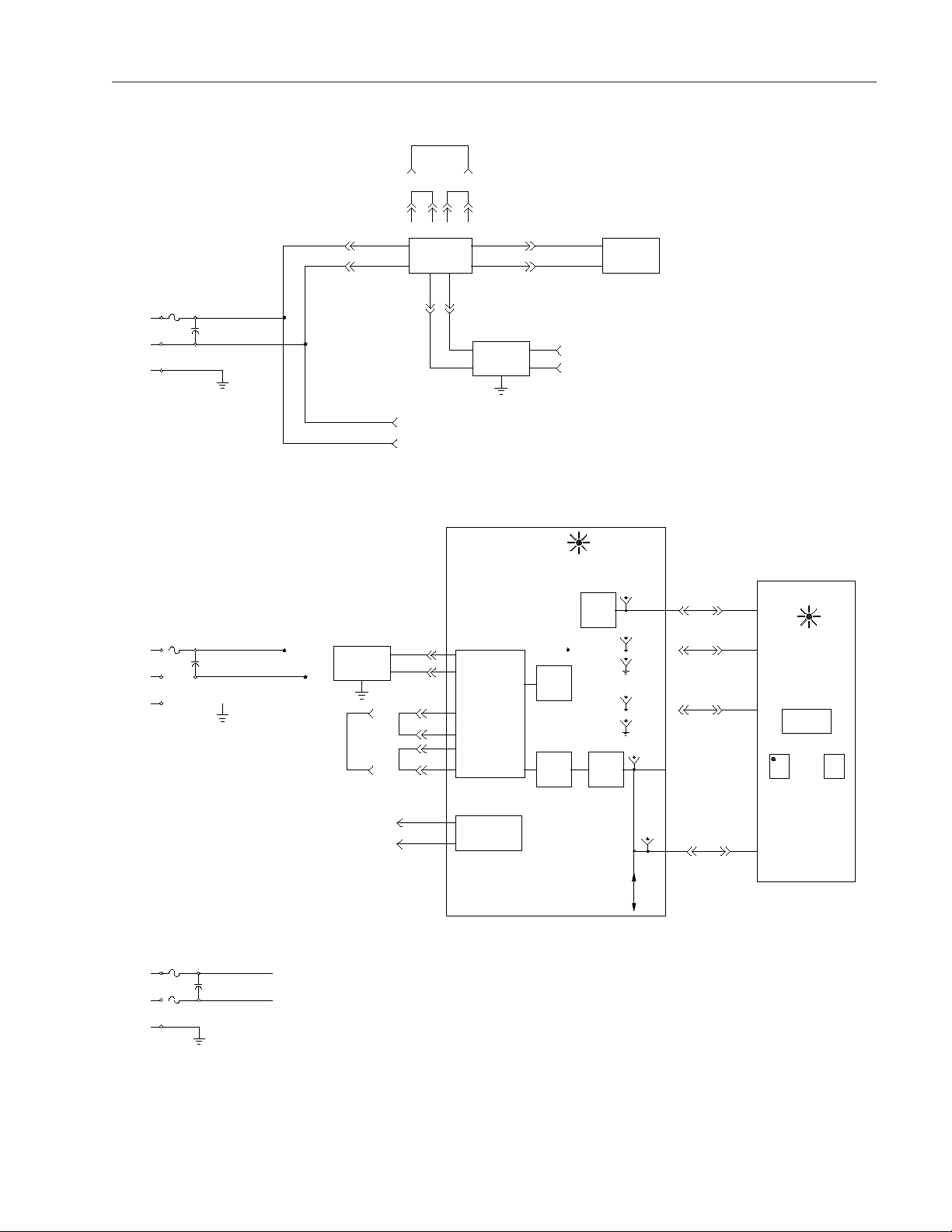
Figure 7
Power Supply Circuits
TROUBLE A
NALYSIS
230V
1
4
115V
N
GND
GND
L
L
N
4
5
TB1 TB1
4 2
5
2
3
3
IC
IC
115 VAC
(BK)
(W)
(W)
(BK)
J1
J2
LINE
FILTER
J7
J8
230 VAC 115 VAC
1 2 3 4
TRANSFORMER
J5
(BR)
J17
TO POWER
I/O BOARD
J18
J7
J5
J3
J8
BOARD
J4
J6
J6
(BL)
LINE
FILTER
TO POWER
I/O BOARD
(SEE NOTE)
TRANSFORMER
(BL)
(BR)
RECT
BRIDGE
RECT
BRIDGE
J4
J6
PRINTER
TO POWER
I/O BOARD
POWER
DS10
+5V
REG
RECT
BRIDGE
TP1
+5V
TP2
+14V
TP3
GND
TP5
+14V
TP6
GND
+24V
TP8
J2-5 J1-5
J2-2 J1-2
J2-3 J1-3
CONTROL
PC BOARD
POWER
DS10
(ON BACK
OF PCB)
DISPLAY
ON OFF
2
4
L1
IC
5
L2
GND
3
2F
230 VAC AND
DUAL VOLTAGE
MODELS
(W)
(BK)
J17
J18
HEATER
CONTROL
CIRCUIT
TP7
12V
J2-16 J1-16
TEST POINTS
TP1 -14 VDC
TP2 +14 VDC
TP3 GROUND
TP7 +5 VDC

22
TROUBLE
ANALYSIS
Heater Control Unit
petSerudecorPnoitcAevitcerroC
1
.draoBCP
otloocotrebmahcehtwollA
ehtretnE.erutarepmetmoor
sserP.sunemputesyrotcaf
ehtlitnunottubmargorpeht
TAEH"",TSETRETAEH"
sserP.deyalpsidsi"0FFO
ehtrewopotnottubtratseht
dnoces01dexifarofretaeh
yalpsidehtnehW.noitarud
kcehc"NOTAEH"swohs
O/IrewoPno)retaeH(1SD
:FFOsi1SDfI
CPO/IrewoPneewtebnoitcennocelbacnobbirkcehC
.draoBCPlortnoCdnadraoB
.draoBCPlortnoCecalpeR
.draoBCPO/IrewoPecalpeR
2
3
4.retaehfoytiunitnockcehC.tiucricnepofiretaehecalpeR
5.RSSretaehkcehC
.hctiwsffo-tuc
dna71JtatupnicarofkcehC
.draoBCPO/IrewoPno81J
lamrehtfoytiunitnockcehC
.snoitcennockcehC
.erutarepmetmoortatiucricnepofiecalpeR
 Loading...