

Page 1

3UR7DON
& HOOXOD U $ 5 8
INSTRUCTION MANUAL
1272M001
Manual Revision: 7 - July 2002
Page 2

Contents
1. Operations Overview
Cv2 capabilities ...........................1-1
What constitutes an alarm? .................1-1
How are alarms processed? .................1-2
What actions should occur when an
alarm is detected? ...................1-3
How do you want to respond to an
alarm call?..........................1-4
What if an alarm is not acknowledged? .......1-5
What do you want the Cv2 to do when
you call it?..........................1-5
Sending remote control commands ..........1-5
Indicators ..............................1-6
2. Installation
3. Configuration with the PC
Troubleshooting ..........................1-6
Antenna requirements .....................2-1
Mounting ................................2-1
Input port connections .....................2-2
Output port connections ...................2-4
Configuration programming connection .......2-4
PC requirements ..........................3-1
Installing the program......................3-1
Starting the configuration program...........3-1
The desktop ..............................3-1
Configuring the Cv2 .......................3-3
Hardware...........................3-3
Points .............................3-5
Groups .............................3-12
Directories..........................3-15
General ............................3-17
Configuration programming.................3-18
4. Voice Storage and Configuration with the Telset
Setup ...................................4-1
Access ..................................4-1
Commands ...............................4-1
Telset programming summary...............4-5
5. Specifications
General ..................................5-1
Programming features .....................5-1
Telephone ...............................5-2
Options..................................5-2
6. Warranty ...................................6-1
Page 3

Operations Overview 1-1
1. Operations Overview
The purpose of this chapter is to provide an overview of the Cv2 capabilities. Chapter topics are
organized in the same order that you would follow in setting up the system. Read this chapter
carefully before proceeding with the installation and programming of the Cv2. For more details
on configuring the operation through the programming software, refer to Chapter 3,
Configuration.
1.1 Cv2 Capabilities
When an alarm occurs, the Cv2 places a call using its built-in cellular phone and announces
the alarm condition using stored voice messages. Alarm messages consist of the site ID
phrase, the group phrase and the alarm message phrase that are stored at voice programming
time. The group phrase is used if the alarms have been grouped to provide different activities
for different alarm conditions. The unit can also be called up and interrogated to obtain
current alarm conditions and readings.
The Cv2 has eight hardware inputs that can be programmed to accept either digital or analog
signals and eight hardware outputs. Inputs can be independently configured to operate in
these modes:
digital monitoring contact closures or voltage levels
watchdog monitoring for the absence of a periodic event
totalizer counting events
interval measuring the time duration of events
analog measuring 0 to 5 volt signals
Outputs can be set to operate as either on/off controls or as timed controls.
1.2 What constitutes an alarm?
Alarm conditions can be defined for digital, watchdog and analog inputs. Totalizers and
interval inputs are used for measurement purposes and do not generate alarms. The signal at
the input is conditioned by a debounce timer that ensures the level is valid before accepting it.
A digital input has normal and alarm states that can be defined as either when the input is high
or low. After the input signal has been qualified by the debounce timer, it can be registered as
an alarm when the input is active, or it can be latched to detect a pulsed condition. The voice
message for a digital input is programmed to announce the alarm condition that it is
monitoring, e.g. “Intrusion Alarm”.
Watchdog inputs use a timer that is restarted by changes at the input. If this timer expires
because it has not been restarted within the programmed interval, an alarm will register. Like
the digital input, the watchdog can be set as either an active-only or latched alarm. The voice
message for a watchdog is similar to a digital, e.g. “Tower Strobe Failure”.
B1272M001
BARNETT ENGINEERING LTD. ProTalk Cv2
Page 4
Operations Overview 1-2
8
8
Analog inputs convert the voltage level to a digital value and perform a comparison against
the programmed low and high setpoints. An alarm is present when the measured value is
above or below the setpoint. Alarm messages are spoken using the stored phrase with either
“High” or Low” appended depending on which setpoint has been exceeded. The actual
reading, including decimal place notation and engineering units, is spoken when the Cv2 is
interrogated.
The latching alarm function is also available for analog inputs.
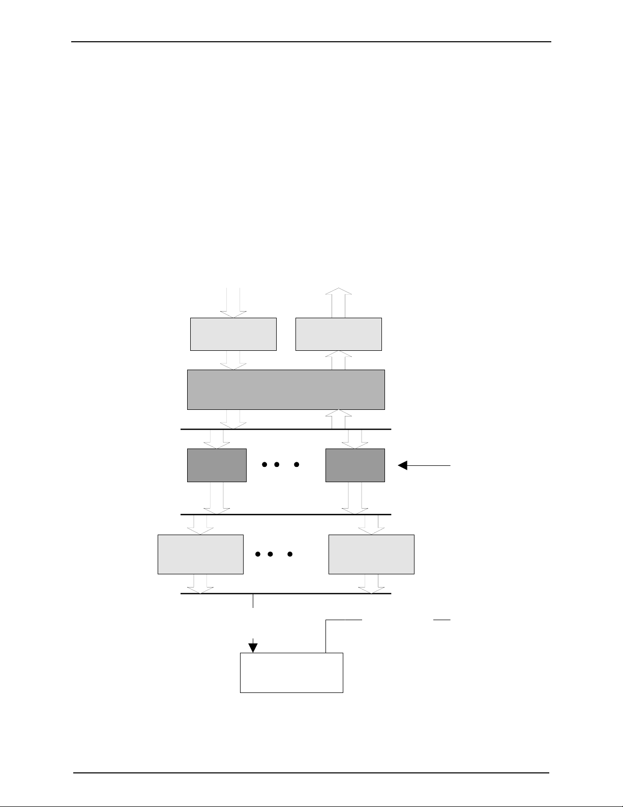
1.3 How are alarms processed?
The way in which the Cv2 processes alarms is shown in Figure 1.
INPUTS
HARDW A RE
INPUTS
UP TO 30 INPUTS OR OUTPUTS
GROUP
1
DIRECTORY
A
OUTPUTS
HARDW A RE
OUTPUTS
POINTS
GROUP
6
DIRECTORY
F
DIALOUT
COMMANDS
TELEPHONE
PORT
Figure 1 Cv2 Block Diagram
B1272M001
BARNETT ENGINEERING LTD. ProTalk Cv2
CONTROL
COMMANDS
Page 5

Operations Overview 1-3
The hardware input and output ports are activated in the Points section to become part of the
monitoring and control process. There are 30 points which can be referenced to any of the I/O
ports. This allows an analog input to be used by more than one point and monitored for
multiple setpoints, as would be the case where minor and major alarms are required.
If you do not want all of the points to generate the same response when they detect alarms,
they can be placed into different groups. Six groups are available, each with independent
timers and control codes. When a group detects an alarm condition in one of its assigned
points, it executes the sequence of actions found in the current directory. A group can use any
of the six directories to perform the callout function, plus the directory selection can be
changed by using the shift control feature.
1.4 What actions should occur when an alarm is detected?
All alarm conditions will be processed by placing a call on the cellular phone. The called
number and the activities that occur with different alarms are determined by entries in the
directories. A directory contains the sequence of actions that will occur when a group has an
active alarm. Instructions for dialing, speaking, inserting delays and signaling are placed in
the directory in the order in which they are to be performed. There are a total of six
directories; each can contain a unique sequence of activities that will be performed when
alarm conditions exist.
To best describe how a directory controls alarm reporting activities, an example directory
programming session follows. For more information on the directory summary and dialog
box, refer to Chapter 3. The opening window for a directory displays a summary of the
activities that it will perform when an alarm is detected. The directory summary is arranged
as lines; each line represents the sequence of events that will take place during one callout. If
a Dial command is the first entry on the line, the Cv2 will call the programmed number and
then execute the remainder of the commands on that line. After the last command on the line
is competed, the call will be terminated. Commands such as Auto Ack and Wait, when used
as single line commands, do not initiate a call. For a basic sequence where the Cv2 is to call a
phone number and speak the alarm message, the directory line contains the Dial and Voice
commands appearing as:
1. [DIAL]2458829 [VOICE]
This line will cause the Cv2 to place a call to 245-8829 and then speak the Site ID, Group
Name and alarm message, or messages, for all active points. Unless programmed not to, the
Cv2 will append the phrase “Enter Acknowledge Code” at the end of the alarm announcement
and wait for the code to be returned. If the code is received, the alarm sequence will be
terminated until a new alarm occurs. Failure to receive an Acknowledge Code will advance
the sequence of operations to the next line in the directory. If the commands contained in the
last directory line have been completed without reception of an Acknowledge Code, the Cv2
waits for the time interval set in the timers before repeating the process by starting over at
directory line 1.
During execution of the Voice command, the Cv2 will try to announce the alarm messages
three times with a one minute limit for the total announcement duration.
B1272M001
BARNETT ENGINEERING LTD. ProTalk Cv2
Page 6

Operations Overview 1-4
For example, to call four telephone numbers, the directory would appear as:
1. [DIAL]2458829 [VOICE]
2. [DIAL]2336700 [VOICE]
3. [DIAL]9842121 [VOICE]
4. [DIAL]9843316 [VOICE]
If you want an alert tone to precede the voice message the directory line would look like this:
1. [DIAL]2458829 [ALERT] [VOICE]
The next example shows a sequence that is used to call a numeric paging terminal. After the
call is placed there is a four second delay for the paging terminal to respond before the Cv2
sends the number to be displayed on the pager. When calling a paging terminal, it is
sometimes useful to allow the called party time to call the Cv2 back and acknowledge the
alarm before the Cv2 advances to the next line in the directory. This can be done by using the
Wait command on its own line; the entry below will cause a four minute delay before the next
line is executed.
1. [DIAL]2458829 [WAIT]4 [DTMF]4567
2. [WAIT]240
Directory lines can be added, removed, or modified and new lines can be inserted between
existing lines.
1.5 How do you want to respond to an alarm call?
After the Cv2 has finished speaking the alarm messages, it prompts the called party with the
phrase “Enter Acknowledge Code” and then waits five seconds for the code to be returned. If
the code is received, it will terminate any further callout activities until a new alarm occurs;
otherwise, it will proceed to the next line in the directory. There is a Temporary
Acknowledge Time that can be set in the General section that will override the operation of
the Acknowledge Code. If the temporary time is set to a value other than Off, and the
received Acknowledge Code has the digit # appended to it, the Cv2 will remain in the
acknowledged state only for this time interval. After the timer has expired and if the alarm
condition still exists, the Cv2 will resume alarm reporting. This feature is used as a safety
measure to ensure that an alarm cannot be acknowledged and then left unattended.
Each group has its own Acknowledge Code which only affects points that have been assigned
to the group. Other groups with different Acknowledge Codes will continue alarm reporting
if they do not receive their own code.
Using the Auto Ack command in a directory will cause the Cv2 to automatically acknowledge
any alarms that are in the group using the directory. This feature must also be enabled for that
group, since other groups of points may be using the same directory. Auto Ack must be on
the last line in a directory since any further commands will never be executed.
Another method of acknowledging the Cv2 is by activating the special function that allows
hardware inputs to be used as local acknowledge controls.
B1272M001
BARNETT ENGINEERING LTD. ProTalk Cv2
Page 7

Operations Overview 1-5
1.6 What if an alarm is not acknowledged?
When the last line in the directory has been completed without receipt of an Acknowledge
Code, a two-stage timer is used to determine when the directory sequence is repeated again.
This timer has two sections: a Short Timer which operates for the number set in Short Cycles,
and a Long Timer which begins after the Short Timer has completed its cycles. This provides
a means of varying the repetition cycle over a period of time.
1.7 What do you want the Cv2 to do when you call it?
In addition to reporting alarms, the Cv2 will also answer incoming calls. This allows you to
interrogate the unit, operate control outputs and change shifts. You can control the level of
security that is presented to incoming calls. With the lowest level, the call will be answered
with the Site ID phrase, the phrases for any groups that have alarms, followed by the prompt
“Enter Command Code”. An Access Code is not required. At the next level of security, the
Cv2 will announce the Site ID phrase and then wait ten seconds for the password code before
allowing access to alarm information or other control functions. At the highest level, the call
is answered but there are no voice prompts; the caller has ten seconds to enter the Access
Code.
Each group of alarms has its own Interrogate Code. When the code is entered, the alarm
status for points in that group is spoken. For digital and watchdog points, the stored phrase
for that point is spoken. Analog points are spoken with the stored phrase and its status -- high,
low or normal -- followed by the reading. For totalizers, the stored phrase is spoken first
followed by the current accumulated value. Interval timers respond with the stored phrase and
the last captured interval.
Control outputs respond with the stored phrase followed by either ‘On’ or ‘Off’ indicating
their current state.
1.8 Sending remote control commands
Points designated as outputs can be controlled using the programmed codes. These codes can
be sent to the Cv2 either during a reporting sequence or when a call is placed to the unit.
During the alarm reporting sequence, the control codes may be sent after the “Enter
Acknowledge Code” prompt is heard. For the next five seconds, the Cv2 will accept
Acknowledge, Interrogate or Control codes. With each received code, the command will be
performed and a prompt for another command entry will then be spoken. For a remote control
output, the status of the output will be spoken after the received code has been executed.
When the unit is called and after the Access Code, if required, has been entered, the prompt to
“Enter Command Code” will be issued.
In either case, the call will be terminated if a valid code is not received during the ten second
window.
B1272M001
BARNETT ENGINEERING LTD. ProTalk Cv2
Page 8

Operations Overview 1-6
1.9 Indicators
The Cv2 has four LED indicators to show the operation of the unit and assist in troubleshooting.
When the Cv2 is initially powered up, the four LEDs will do the following:
& All will turn on for approximately one second.
& Hook will flash on and off for one second then go out.
& Tone will flash on and off for one second then go out.
& Voice will flash on and off for one second then go out.
& Alarm will flash on and off for one second then go out.
& Hook On power-up, following the initial flashing of each LED, Hook flashes until the
Cv2 has found cellular service. Once the unit has logged onto the cellular
network, the Hook indicator goes out. Hook also flashes while a call is being
placed. After the call has been processed, Hook is on steady until the end of the
call when it goes out.
& Tone Tone blinks once for each DTMF digit that is either received or transmitted.
& Voice Voice is on when the Cv2 is speaking. On power-up, following the initial flashing
of each LED, it will go on continuously for 2 seconds if any section of the stored
database, voice or vocabulary memory is corrupt. If this occurs, the configuration
should be downloaded into the unit and the voice recordings checked for validity.
Voice flashes briefly every second to indicate that the Cv2 is operating correctly.
& Alarm If an unacknowledged alarm is present, the alarm indicator will flash. When the
alarm is acknowledged, Alarm is on steady. When no alarms are present, Alarm
is off.
1.10 Troubleshooting
Is there power to the unit?
When power is first applied to the Cv2, it will flash the Hook indicator until it establishes contact
with the cellular service. At any other time, the presence of power, and correct operation, are
indicated by the brief flashing of the Voice LED every second.
Does the cell phone work?
Use the local call feature to determine if the unit is working properly. If the call cannot be
completed, query the cell phone to see if it responds - any parameter can be used here. Query the
RSSI (Received Signal Strength Indicator) in the phone to see if there is coverage in the area.
The message “error” will be returned if there is no coverage. This can possibly be corrected by
improving the antenna system.
B1272M001
BARNETT ENGINEERING LTD. ProTalk Cv2
Page 9

Operations Overview 1-7
Are the inputs connected properly?
For digital inputs that are programmed for standard digital operation, create an alarm condition
on the input and confirm that the Alarm LED comes on. Make sure the input is applied long
enough for the debounce to time out. If the Alarm indicator does not come on, the problem is not
necessarily with the input connection. Check that the input is enabled as a valid point, the
associated group is enabled, and the directory is programmed to call out..
For analog inputs, interrogate their group to hear the scaled value at the input.
The unit does not dial out.
Check the Alarm LED to confirm that an alarm is present. If this indicator is not flashing, the
Cv2 will not call out. Check that the input is enabled as a valid point, the associated group is
enabled, and the directory is programmed to call out.
I cannot call into the unit.
If you receive a recording from the telephone company indicating the user is not available, there
may be a problem with the installation or you may be calling the wrong number. Use the
programming phone to confirm the telephone number in the unit.
B1272M001
BARNETT ENGINEERING LTD. ProTalk Cv2
Page 10
Installation 2-1
2 Installation
The Cv2 can be installed before or after the configuration has been transferred from the PC to the
unit. If the Cv2 is configured in the shop before it is installed in the field, all of the programmed
parameters and voices will remain unchanged in the unit’s non-volatile flash memory.
2.1 Antenna requirements
The antenna used for your installation will depend on the proximity of the alarm unit to the
cellular carrier facility. If the installation is very close to a cell site, a portable style antenna
can be connected directly to the RF connector on the Cv2. If the distance between the
installation and the nearest cell site does not provide adequate signal strength to operate with
the small antenna, then an outdoor or other high gain antenna will be required. Antenna
system details for this type of antenna installation -- antenna type, height and coaxial cable
type -- will depend on the particulars of the site.
If you use the directly connected antenna, it should be oriented vertically.
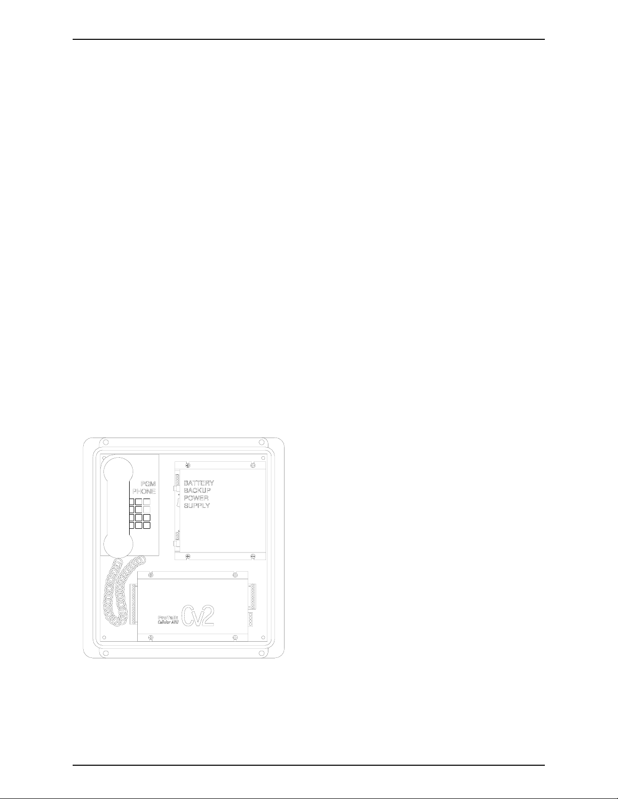
2.2 Mounting
The Cv2 is available in two versions: the packaged unit which is housed in an enclosure
complete with a battery backed power supply and a programming phone set, or the standalone version which is the Cv2 alarm reporter without the above accessories.
2.2.1 Packaged model
The packaged model should be mounted
onto a wall or other vertical surface in a
location where the temperature cannot
exceed the Cv2 rating.
Before connecting AC power, confirm that
the setting of the voltage range switch on the
power supply module is set for the correct
input, either 110 or 220 VAC.
Connect AC power to the terminal strip on
the power supply module. Connect the
antenna or coaxial feed line to the remote
antenna onto the TNC coaxial jack on the
Cv2.
Connect the input and output signal lines
between the Cv2 and the equipment that you
want to monitor and control. Details of the
Figure 3 Packaged Cv2
input and output ports are discussed later in
this chapter.
B1272M001 BARNETT ENGINEERING LTD. ProTalk Cv2
Page 11
Installation 2-2
2.2.2 Stand-alone model
The stand-alone Cv2 can be mounted on a flat surface. Make sure that there is enough room
around the unit to make connections. The environment should be clean and dry, with an
ambient temperature that
o
does not go below -20
or above +50
o
C.
C
Connect a DC power
source to the terminals on
TB2. The Cv2 requires up
to 1.5 Amps to operate;
the supply should be sized
accordingly. Input power
to the unit is protected by
a Polyswitch current
limiter. If a fault develops
in the CV2, this switch
Figure 3 Stand-alone Cv2
will become a high
resistance to prevent damage to the equipment or the power supply. Once this switch has
been activated, the fault must be removed before it will reset and allow current to pass through
to the equipment.
Connect the antenna or coaxial feed line to the remote antenna onto the TNC coaxial jack on
the Cv2.
Connect the input and output signal lines between the Cv2 and the equipment that you want to
monitor and control. Details of the input and output ports are discussed in the next section.
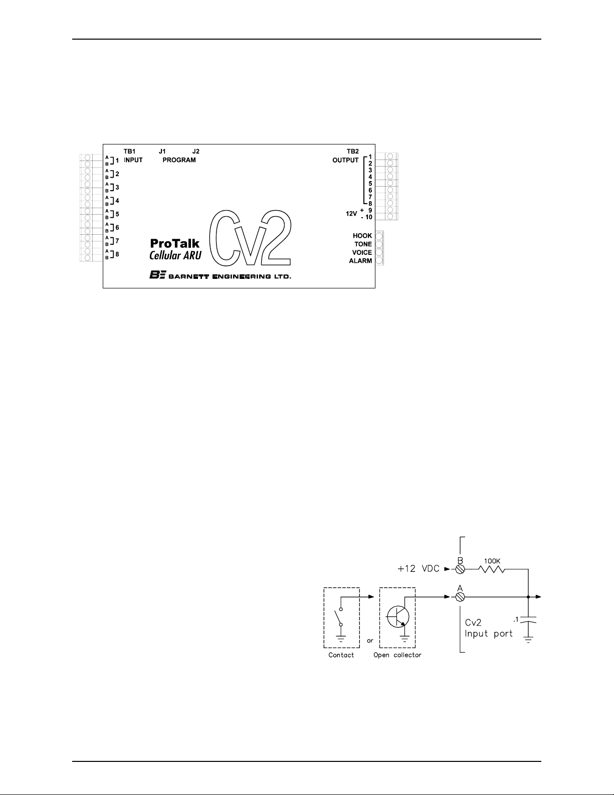
2.3 Input port connections
The input ports can be connected to a variety of contact or voltage sources for monitoring
purposes. Select a wiring configuration that matches your alarm source from one of the
following arrangements:
2.3.1 Ground closure alarm signal
For alarm sources that appear as a ground
closure, either through a mechanical contact
or an open collector driver, the input should
be wired according to Figure 4. If the input
is normally open and goes to ground during
an alarm condition, program the Hardware
section for this input as “Normally High”. If
the reverse is true, set the input to “Normally
Low”.
Figure 4 Ground Closure Input Wiring
B1272M001 BARNETT ENGINEERING LTD. ProTalk Cv2
Page 12
Installation 2-3
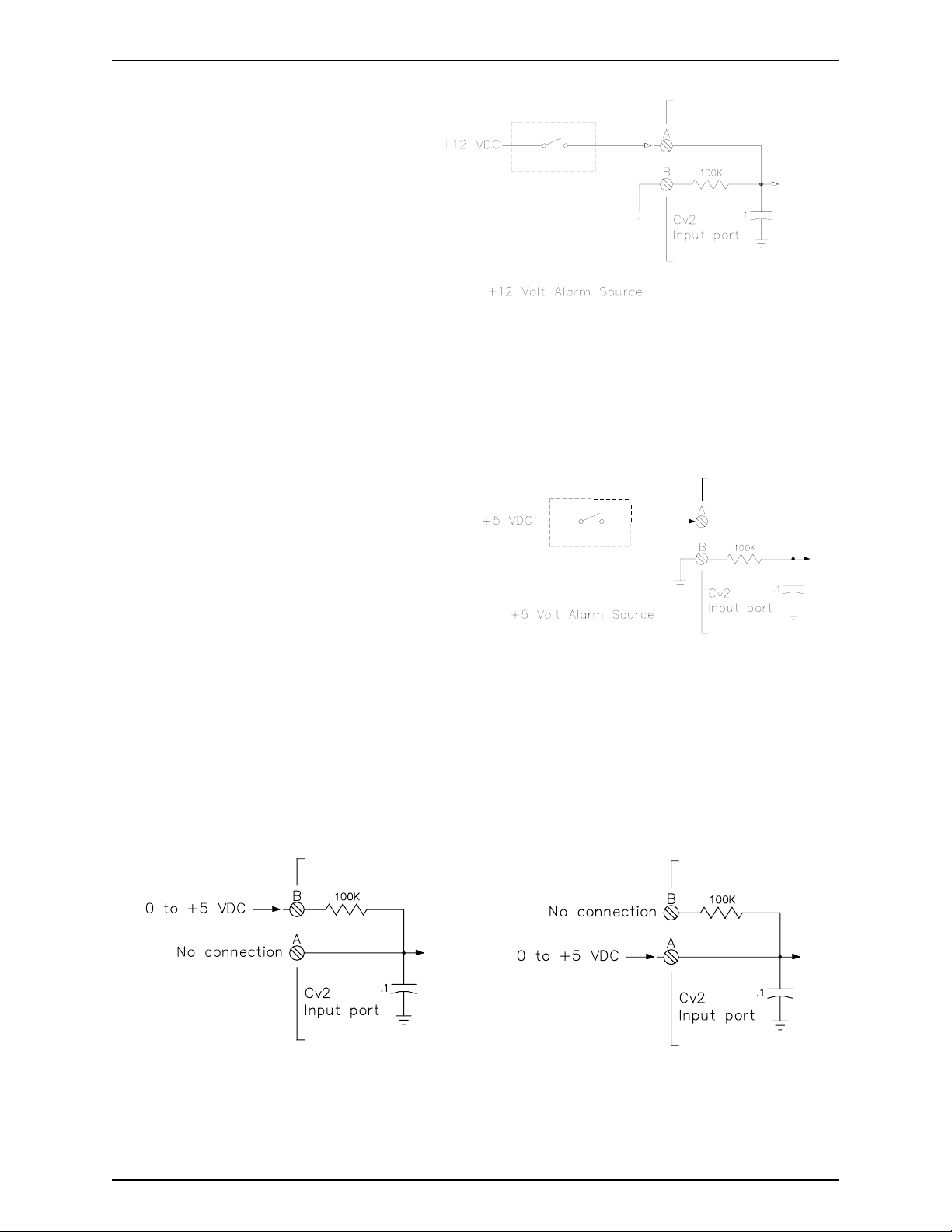
2.3.2 +12 volt alarm signal
The input will accept an alarm signal
that switches between 0 and +12 volts
with the wiring arrangement shown in
Figure 5.
If the signal switches between +12 volts
and an open circuit, as in the case of a
relay contact, the ‘B’ terminal must be
connected to ground to ensure that the
logic level goes to ground when the
voltage is removed.
Figure 5 +12 Volt Input Wiring
2.3.3 +5 volt alarm signal
Figure 6 shows how an alarm signal that
switches between +5 volts and ground is
wired. If the alarm signal does not have a
true ground level, terminal ‘B’ must be
connected to ground.
Figure 6 +5 VDC Input Wiring
2.3.4 Analog input
For analog signals, either of the wiring configurations shown in Figures 7 and 8 can be used.
The connection shown in Figure 7 will provide additional filtering of the signal.
Figure 7 Analog (filtered) Input Wiring
B1272M001 BARNETT ENGINEERING LTD. ProTalk Cv2
Figure 8 Analog (unfiltered) Input Wiring
Page 13
Installation 2-4
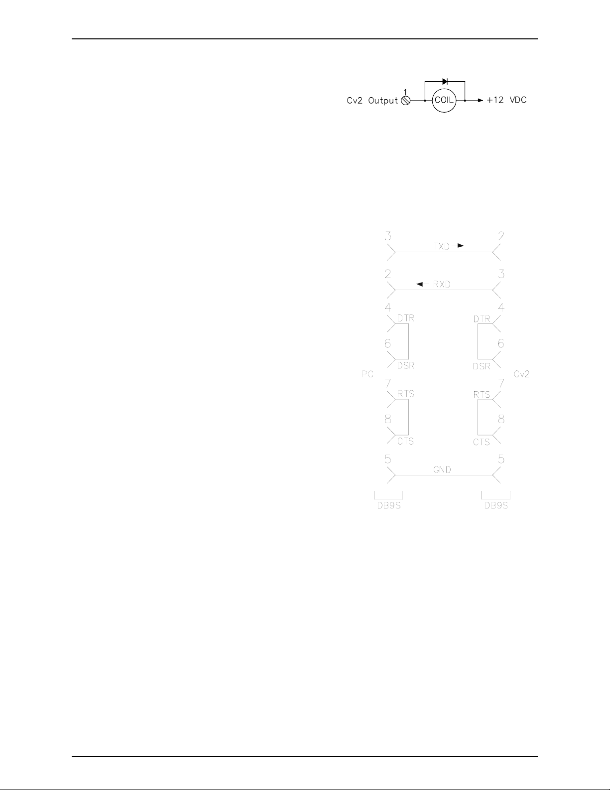
2.4 Output port connections
The output ports are open collector drivers that can
sink up to 500 mA through a load connected to a
voltage of up to +50 VDC. If an inductive load
such as a relay is connected to an output, install a
Figure 9 Output Wiring
protective reverse-biased diode across the load to
prevent damage to the output from the inductive flyback voltage. Figure 9 shows the
connection for an output used as a relay driver.
2.5 Configuration programming connection
When the configuration database is transferred from
the PC to the Cv2, a serial communications cable is
connected between the COM port of the computer and
the serial programming port, J1, on the Cv2. When
the cable is attached to the connector on the Cv2, the
DTR signal is sensed by the Cv2 and it enters the
programming mode. The cable used to connect
between the two pieces of equipment is shown in
Figure 10. To restore the Cv2 to operation, the cable
must be unplugged. The serial programming cable is
supplied with the Cv2.
J1 can also be used to program the cellular radio in
the Cv2. When the Cv2 detects that the serial port is
being used to program the cellular radio, it will
automatically route the communications to the radio.
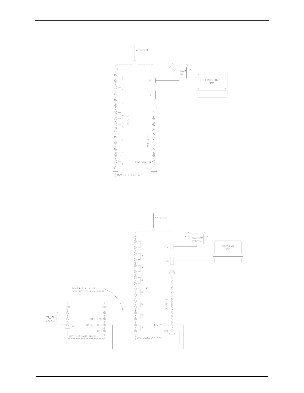
Figure 11 shows a stand-alone Cv2 installation. The
programming PC is present only when a configuration
database is be transferred to or from the Cv2; the
programming telephone can be either permanently
installed or used only for voice recording. Note that
Figure 10 Serial Cable
the phone set can also be used to place outgoing calls,
if required. If the Cv2 is to remain operational during a power outage, the DC power provided
to the unit must be uninterrupted.
Figure 12 shows a packaged Cv2 installation. The programming PC is present only when a
configuration database is be transferred to or from the Cv2; the programming phone is part of
the package and can also be used to place outgoing calls. The built-in power supply contains
an 8 AH battery and is capable of running the Cv2 for at least 12 hours during a power outage.
The power supply has a power fail output signal that can be connected to any of the input ports
on the Cv2 and programmed as an alarm point.
B1272M001 BARNETT ENGINEERING LTD. ProTalk Cv2
Page 14
Installation 2-5
Figure 11 Stand-alone Cv2
B1272M001
Figure 12 Packaged Cv2
BARNETT ENGINEERING LTD. ProTalk Cv2
Page 15

Configuration using the PC 3-1
3 Configuration using the PC
This chapter describes how to install the programming software and configure the operation of
the Cv2. When the configuration is complete, it can be viewed through the Summary command
found on the File pull-down menu. In the summary, Warnings should be checked to ensure that
there are no improper settings in the configuration before it is transferred to the Cv2.
3.1 PC requirements
The minimum requirements for the PC used to run the Cv2 programming software are:
• 386 processor
• Windows 95
• 8M RAM
• SVGA screen
• Serial COM port
3.2 Installing the program
The program diskettes supplied with the Cv2 contain the configuration software and the
software installation utility. Place disk 1 into the floppy drive and select the program
SETUP.EXE using Run in the windows Start menu. Follow the instructions and the
installation program will automatically install the configuration program onto the hard drive.
3.3 Starting the configuration program
To start the program, click on the Cv2 icon that appears in the installed location. The program
will load and search for the default startup files:
Cv2.dat - the configuration database
Cv2.cfg - the serial port setting
If these files are not found, default files will be created and a warning posted.
3.4 The desktop and how to access programming functions
At the top of the desktop are drop-down menus and buttons on the taskbar that launch the
various operations in the program. The taskbar buttons duplicate the operations found in the
menu. To activate on-line help, press F1 or select the Help menu at the top of the desktop.
Context help for the controls is available when dialog boxes are open. Press the Help
question mark in the upper right of the dialog box, place the curser with the question mark
over the control, then click the left mouse button.
The menu and button operations are summarized in the following section.
B1272M001 BARNETT ENGINEERING LTD. ProTalk Cv2
Page 16

Configuration using the PC 3-2
3.4.1 File Operations
File Open
If you do not want to edit the default database, use the File Open button to select a different
configuration file. This will bring up the standard Windows File Open dialog box where you
can open another .dat file.
File Save As
To save the current configuration under a different name, use the Save As button to bring up
the standard Windows Save As dialog box. Enter a new name and save the file. After the file
has been saved under a different name, subsequent save operations will store the configuration
data with the new name.
File Save
Use the Save button to save the current configuration database. If the name has not been
changed during this session using Save As, the data will be stored as the default Cv2.dat file.
If the name has been changed then the file will be saved under the new name.
3.4.2 Hardware
Inputs
This section is used to set the type of input for each port and select basic hardware settings.
Outputs
This section is used to set the type of output for each port and select basic hardware settings.
3.4.3 General
Settings that concern the operation of the entire Cv2 are entered in the General section.
3.4.4 Groups
Each of the six groups can be set to provide different alarm reporting operations for
selected points.
3.4.5 Points
In the points section, any of the hardware inputs and outputs can be selected for the Cv2
to use as alarm reporting or remote control functions. There are 30 points available.
B1272M001 BARNETT ENGINEERING LTD. ProTalk Cv2
Page 17

Configuration using the PC 3-3
3.4.6 Directories
When an alarm is detected, the Cv2 will perform a specific sequence of events
determined by the entries in the directory. Six directories are available, providing
different actions for different groups.
3.4.7 Programming
The programming section is used to transfer the configuration database between the PC
and the Cv2. Recorded voices can also be transferred from the Cv2 and then back.
3.5 Configuring the Cv2
When configuring the Cv2, the sequence described in the following section is the simplest
way to get the unit operational. If the Cv2 uses any of the special port functions -- Alarm
Active, New Alarm, Acknowledge Received, Local Acknowledge or the Totalizer Reset
Input -- you must consider the relationship between these functions and the Hardware, Groups
and Points sections when configuring the unit.
3.5.1 Hardware section
Start with the Hardware section to establish settings for the input and output ports. Input ports
can be configured as Digital, Analog, Watchdog, Totalizer or Interval types. Each port can be
independently set to one of these types; an individual port can have only one type assigned.
Output ports can be either On/Off or Timed types.
To select an input for configuration click on the Hardware Inputs button to bring up the
summary of the input settings. Each of the eight inputs will be shown along with its current
type and hardware settings. The input to be edited is highlighted and can be selected by
pressing Enter, double-clicking on the line, or selecting the Edit Line function from the
menubar. Selecting an input for editing will produce the dialog box for that input type.
After an input or output port has been configured, it can be activated in the Points section for
alarm reporting, monitoring or control purposes. Input ports can be changed to one of the
other types by selecting from the Change Input Port drop-down list. Changing the input type
will force any variables used in the Hardware section to the default value and will remove any
points that make use of this port. Output ports can be changed from one type to the other.
Digital Input
A Digital input represents the basic input type, responding to either high or low signals to
indicate the status of the port. Wiring of the port determines if ground closure or voltage
signals are being monitored.
Debounce times are set to qualify the state of the input before it is considered valid. Two
debounce time ranges, seconds and minutes, are available. The seconds range has a
maximum value of 1638 seconds (27 minutes) with a resolution of 25 msec. For longer
debounce times the minutes range should be used. When set to minutes, the debounce
timer has a maximum value of 65,535 minutes with a resolution of one minute. For short
B1272M001 BARNETT ENGINEERING LTD. ProTalk Cv2
Page 18

Configuration using the PC 3-4
debounce times, use the seconds timer to avoid the inaccuracy introduced by the one
minute resolution.
Default Debounce time: 0.05 sec
A Digital input port can also be used to perform special functions in the Cv2. In the
Groups section, it can be selected for the Local Acknowledge function, and in the
Hardware section it can be set to operate as a Reset Input for a Totalizer.
Watchdog Input
A Watchdog timer is used to monitor periodic events and will produce an alarm if the
event does not occur within the programmed Watchdog interval. Each time an event
occurs at the input, the timer is reloaded with the programmed value. When the timer has
expired without a refresh event, the alarm is set. Refresh activities can be changes from
low to high, changes from high to low, or both.
Watchdog input types use two timers for their operation: the Debounce timer and the
Watchdog Interval timer. Refer to the preceding Digital input description for details on the
Debounce timer. Two Watchdog time ranges, seconds and minutes, are available. The
seconds range has a maximum value of 1638 seconds (27 minutes) with a resolution of
25 msec. For longer Watchdog times the minutes range should be used. When set to
minutes, the Watchdog timer has a maximum value of 65,535 minutes with a resolution of
one minute. For short Watchdog times, use the seconds timer to avoid the inaccuracy
introduced by the one minute resolution. When setting the two timers, take into
consideration the relationship between the two. The Debounce time can not be greater than
the Watchdog Interval; otherwise a constant alarm condition will occur.
Default Watchdog time: 10 min
Interval Input
Interval timers measure the time interval that an input is active, either how long it is high or
how long it is low. The input is conditioned by the Debounce timer which is described in
the Digital input section. When setting the Debounce timer, consider the anticipated
duration of the interval. Since the Cv2 registers a change only after the Debounce time,
long debounce settings will affect the accuracy of the measurement.
Totalizer Input
Totalizer inputs measure the number of times that an event has occurred at the input. The
event can be a high to low transition, a low to high transition, or both. Before the change is
considered valid, it is conditioned by the Debounce timer - described in the Digital input
section. Take into consideration the expected time period between events when setting the
Debounce timer.
The count in the totalizer can be reset by two methods: by sending the Reset Code entered
in the Points section, or by using the Reset Input selection in the Hardware setup.
B1272M001 BARNETT ENGINEERING LTD. ProTalk Cv2
Page 19

Configuration using the PC 3-5
Analog Input
Setting the input port type to Analog allows measurement of voltages between 0 and
+5 volts. As with the other input types, the definition of an analog input is completed in
the Points section where the range, setpoints and units are assigned.
An Analog port can be changed to one of the other input types by selecting from the
Change Input Port drop-down list. Changing input type will force any variables used in the
Hardware section to the default value and will remove any points that make use of this
input.
On/Off Output
On/Off outputs operate with two DTMF codes that are set in the Points section. One code
turns the output On and the other returns it to the Off state. The output will remain in the
last commanded state indefinitely.
To make an On/Off port operational for remote control or as one of the special functions -Alarm Active or New Alarm -- it must be configured and enabled in the Points section.
Timed Output
Timed outputs are activated by receipt of a single DTMF ‘On’ code. This code is set in the
Points section. When the code is received, the output will activate and will remain in that
state until the timer expires or the DTMF ‘Off’ code is received.
Two timer ranges, seconds and minutes, are available. The seconds range has a maximum
value of 1638 seconds (27 minutes) with a resolution of 25 msec. For longer times the
minutes range should be used. When set to minutes, the timer has a maximum value of
65,535 minutes with a resolution of one minute. For short times use the seconds timer to
avoid the inaccuracy introduced by the one minute resolution.
When the command to turn on the Timed output has been received and executed, the Cv2
will announce the current state of the output port. If the timer value is set to a short
interval, it is possible that the output will have returned to the Off state by the time the
status is announced.
To make a Timed port operational for remote control or as one of the special functions -Alarm Active, New Alarm or Acknowledge Received - it must be configured and enabled
in the Points section.
3.5.2 Points section
After the Hardware ports are configured, use the Points section to specify how activities on
these ports are processed. There are 30 points available for use as either input or output
controls. It is in the Points section that inputs are given the ability to generate alarms and
outputs are enabled to perform remote control functions. Each point can be referenced to any
of the input or output ports. When a port is selected in Points it will have the characteristics
that were set in the Hardware section. If a different type of operation is required for a port, it
must be changed in the Hardware section.
B1272M001 BARNETT ENGINEERING LTD. ProTalk Cv2
Page 20

Configuration using the PC 3-6
Each point can be placed into one of the six groups. If a port is used for one of the special
functions, the Group section sets the ports.
To access a point for configuration, select the Points button to bring up the summary of the
settings. Status of the 30 points will be shown along with a brief description of their settings.
Highlight the point to be edited, then select it by pressing Enter, double-clicking on the line,
or choosing the Edit Line function from the menubar. Selecting a point will bring up the
dialog box for that type.
Depending on the type of point, the contents of the dialog box will vary. There are a number
of common settings that appear in all of the point dialog boxes:
Common Settings for Points
I/O Port Selection
If you would like to change the type of input or output, select one of the other available
ports. Changing the port will force the point to its default settings and the settings for
the current point will be lost.
If a port is being used for one of the special functions, an abbreviated Function Code
will also be displayed in the port selection list:
>ACK< Local acknowledge input for one or more groups.
>RES< Reset input for one or more totalizers.
<ALM> Output used to indicate there is an Alarm Active in one or more groups.
<NEW> Output used to indicate that there is an unacknowledged, or New Alarm,
in one or more groups.
<ACK> Output used to indicate that an Acknowledge Code has been received for
one or more groups.
Default Port Selection: Unused, not included in any reporting activities.
Point Name
The Point Name is a 16-character text field where you can enter a description of the
point. This name is used for quick identification in the point summary; otherwise it is
not required for operation of the Cv2. Normally the name assigned is the same as the
voice message programmed into the Cv2 for this point.
Default Point name: empty text string.
Using Group
Each point is placed into a group, which will determine, through a directory, what
actions take place when an alarm occurs. For example, groups could be set up to
process alarms specific to security, maintenance and/or operations. Points would then
be assigned to the group concerned.
Default group: Group 1.
B1272M001 BARNETT ENGINEERING LTD. ProTalk Cv2
Page 21

Configuration using the PC 3-7
Enabled
When a point is enabled, alarm activities will be reported and it can be interrogated for
its current status. A disabled point does not produce alarms and cannot be interrogated.
Changing the enable flag does not alter any of the other settings for this point.
Default Point state: disabled.
Digital and Watchdog Points
Settings for Watchdog points are the same as for Digital points.
Alarm State
Points can be set to register an alarm in two ways: only when the alarm condition is
present, or latched when an alarm condition is first detected. Latched operation means
that the alarm is set when the input change is first detected and will remain in that state
until the group it is using is acknowledged. If the alarm is not latched, it will be
removed as an alarm when the input condition returns to normal.
Default alarm state: when active.
DTMF Tag
The DTMF Tag is used to generate signaling messages for remote equipment. If a
DTMF tag is available, it will be sent if the [SIGNAL] command is present in the
Directory.
The tag can consist of 1 to 7 digits and may use any of the 16 DTMF digits including A,
B, C, and D.
Default DTMF Tag: empty string - no signaling.
Interval Point
An Interval Point uses only the common settings. It cannot generate alarms, but can be
interrogated to obtain readings.
Totalizer Point
Totalizers cannot generate alarms, but can be interrogated to obtain readings. In addition
to the common ones, the totalizer also has the these settings:
Decimal Place
A decimal place can be inserted into the spoken message for a totalizer. Five decimal
locations are available:
XXXXX.
XXXX.Y
XXX.YY
XX.YYY
X.YYYY
B1272M001 BARNETT ENGINEERING LTD. ProTalk Cv2
Page 22

Configuration using the PC 3-8
When the message is spoken, the digits to the left of the decimal (represented by X) and
the digits to the right of the decimal (represented by Y) are spoken with the word ‘point’
between them. The format with the decimal at the far right with no ‘Y’ component is
spoken without the word ‘point’.
Default Decimal Place: no decimal place spoken.
Clear Code
The Clear Code is used to clear the totalizer to a zero reading. When the code is
received, the Cv2 announces that the point has been cleared. The code can consist of 1
to 7 digits and may use any of the 16 DTMF digits including A, B, C, and D.
Default Clear Code: empty string - no code.
Units
If you require the Cv2 to speak engineering units after the numeric value of the
Totalizer, set them in the Units section. Units are subdivided into three components
-- Prefix, Unit and Suffix -- as shown below:
Prefix Unit Suffix
NONE NONE NONE
THOUSAND CUBIC METERS PER DAY
MILLION CUBIC YARDS PER HOUR
MILLI CUBIC FEET PER MINUTE
CENTI PSI PER SECOND
KILO POUNDS
MEGA METERS
GIGA RPM
GALLON
BARRELS
PERCENT
PARTS PER MILLION
Select from the three columns to construct a phrase describing the units for the point.
One, two or three of the selections can be used; if all are set to NONE then nothing will
be spoken after the numeric value.
Default Units: for all three sections is NONE.
Analog Point
Analog points generate alarms when the input value exceeds either the low or high
setpoints. Like Digital and Watchdog points, they have Alarm State and DTMF Tag
settings. The other settings in the Analog Point dialog box are unique to this type of point.
B1272M001 BARNETT ENGINEERING LTD. ProTalk Cv2
Page 23

Configuration using the PC 3-9
Calibrate
Calibration of an analog allows the conversion of the input voltage reading to a value
that is expressed in engineering units. Setpoints are then assigned to the actual
corresponding measurement, and when the point is interrogated, the reading is
announced in engineering units. Calibrate is a secondary dialog box that is activated
from the Analog Point dialog box.
The relationship between the binary reading from the input analog converter and the
decimal value that is used for setpoints and annunciation is established by setting the
Binary and Decimal limits.
Binary Values
The full scale binary range, when an input port is configured for analog operation, is
determined by the internal A to D converter which provides eight bits of resolution.
The minimum binary value is 0 and the maximum value is 255 for the input range of
0 to +5 VDC.
If the sensor that is driving the input port does not produce a full scale output that
corresponds to the Cv2 range, then the binary values can be adjusted to match the
sensor. For example, if a sensor with a full scale range of 1 volt to 5 volts is used,
then set the Cv2 with the binary minimum at 51 (255 x 1/5) and the binary maximum
at 255. If the sensor produces outputs of between 0 and 2.5 volts, then set the binary
minimum to 0 and the binary maximum to 127 (255 x 2.5/5).
The range of the sensor should use as much of the available Cv2 analog input range
as possible in order to maintain a high resolution for the readings.
The minimum and maximum Binary values will correspond to the Decimal
minimum and maximum that represent the actual readings, in engineering units,
being monitored by the sensor.
Default Binary Values: 0 for the minimum and 255 for the maximum.
Decimal Values
Decimal values represent the real physical measurement being monitored by the
sensor. For example, the current or voltage signals correspond to some engineering
value such as gallons or PSI.
Set the decimal minimum to the low end of the range being measured. Set the
decimal maximum to the high end of the sensor scale.
For example, if the minimum for the sensor is 50 rpm and maximum is 800 rpm,
enter these values in the decimal section. Decimal values may be negative, e.g. a
o
temperature range of -40
C to +60oC.
The range allowed for the decimal limits is -999.9 to +999.9. If values greater than
these settings are needed, use a suitable prefix or suffix from Units and scale the
reading to fit in the allowed range. If a sensor was connected to a meter with a range
of 0 to 10,000 gallons per hour, then a suitable scale in the decimal values would be
B1272M001 BARNETT ENGINEERING LTD. ProTalk Cv2
Page 24

Configuration using the PC 3-10
0 as the minimum, 10 as the maximum, with Units set to read ‘thousand’ as the
prefix before gallons.
Once the range of the decimal scale has been entered, then the high and low setpoints
can follow. Both setpoints can be used within a single point. If the low setpoint is
not required, set it to the decimal minimum; if the high setpoint is not needed, set it
to the decimal maximum.
Default Decimal Values:
Minimum: 0
Maximum: +100.0
Low Setpoint: +25.0
High Setpoint: +75.0
Hysteresis
Hysteresis is a quick method of establishing the reset values for the high and low
setpoints. After an analog reading has exceeded the setpoint, either high or low, it
must pass through the reset value before it is considered to have returned to normal.
This prevents a reading that is hovering around a setpoint from constantly going in
and out of alarm. The more unstable the reading, the larger should be the hysteresis.
Hysteresis is calculated as a percentage of the decimal span and then used as an
offset from the setpoint. For the low setpoint, the reset will be above the setpoint and
for a high setpoint, the reset level will be below.
Default Hysteresis: 10% of decimal span.
Units
If you require engineering units to be announced after the numeric value of the
Analog Point, set them in the Units section. Available units are listed in the Points Totalizer section.
On/Off Output Point
In addition to the common settings described previously, there are two DTMF control
codes used with an On/Off output point.
DTMF On Code
When the Cv2 receives the DTMF On code, it sets the output port to the On state. After
the code has been received and the output port set, the Cv2 announces the current status
of the output.
This code can be 1 to 7 digits in length and may use any of the 16 DTMF digits
including A, B, C, and D.
Default DTMF On Code: an empty string - no On Code.
B1272M001 BARNETT ENGINEERING LTD. ProTalk Cv2
Page 25

Configuration using the PC 3-11
DTMF Off Code
When the Cv2 receives the DTMF Off code, it sets the output port to the Off state.
After the Off code has been received and the output port cleared, the Cv2 announces the
current status of the output.
This code can be 1 to 7 digits in length and may use any of the 16 DTMF digits
including A, B, C, and D.
Default DTMF Off Code: an empty string - no Off Code.
Timed Output Point
In addition to the common settings, there are two DTMF control codes used with an Timed
output point.
DTMF On Code
When the Cv2 receives the DTMF On code, it sets the output port to the On state and
the timer begins operation. After the On code has been received and the output port set,
the Cv2 announces the current status of the output. If the timer is set for a short
interval, the output port may have returned to the Off state before the announcement is
made.
This code can be 1 to 7 digits in length and may use any of the 16 DTMF digits
including A, B, C, and D.
Default DTMF On Code: an empty string - no On Code.
DTMF Off Code
When the Cv2 receives the DTMF Off code it sets the output port to the Off state and
terminates the timer operation if it is currently running. The DTMF Off code will have
no effect if the output timer has already expired. After the Off code has been received
and the output port cleared, the Cv2 announces the current status of the output.
This code can be 1 to 7 digits in length and may use any of the 16 DTMF digits.
Default DTMF Off Code: an empty string - no Off Code.
3.5.3 Group section
In some applications, there may be a requirement for different types of alarms to alert different
people. This is handled in the Cv2 by assigning alarms to different groups; there are six
groups available for this purpose. Each alarm point has a selection list for setting the Using
Group parameter. In the group dialog, the directory that it will be using is selected in the Shift
control section. If the group activities are not going to be altered by changing shifts, use the
shift 1 selection for all groups. If the use of directories by a group is going to change through
the Shift Control, enter the appropriate directory into the shift selections.
Each Group has its own Acknowledge Code, Interrogate Code and Timer settings. Activities
for a particular group are performed according to the Shift that is selected. Each shift uses one
of the directories as the instruction source for the sequence of actions that occur during alarm
B1272M001 BARNETT ENGINEERING LTD. ProTalk Cv2
Page 26

Configuration using the PC 3-12
conditions. If a different type of activity is required, such as after hours or weekends, the
change can be quickly made by using another shift to control the Cv2 operation. There are
also a number of special function settings that enable outputs and inputs to operate as controls
and indicators for some internal Cv2 activities.
The settings that can be entered for each group are defined below:
Group Name
The Group Name is a 16-character text field where you may enter a description of the
group. The name is used only for identification purposes; otherwise it is not required for
operation of the Cv2. Normally the name is the same as the voice message programmed
into the Cv2 for this group.
Default Group Name: an empty text string.
Acknowledge Code
The Acknowledge Code is a 1 to 7 digit DTMF string that is used to acknowledge the
group and stop alarm transmission until a new alarm is detected. Each group can have a
unique Acknowledge Code, or different groups can use the same code in order to be
acknowledged simultaneously. In special cases where it is not desirable to have the
Acknowledge Code permanently silence the alarm condition, append the digit ‘#’ when
you send the code and the Temporary Acknowledge Time in the General section will be
used as an override.
Default Acknowledge Code: an empty text string.
Interrogate Code
The Interrogate Code is a 1 to 7 digit DTMF string that is used to make the Cv2 announce
the condition of points in the group. Each group can have a unique Interrogate Code, or
different groups can use the same code in order to generate the status of all groups at once.
Default Interrogate Code: an empty text string.
Enable This Group
To allow this group to be used for alarm reporting, this setting must be enabled. Points that
are used for ‘interrogate only’ have this setting turned off. Groups may also be enabled or
disabled via the local (or remote) programming phone.
Default Group Enable: disabled
Enable Auto Ack
If the Auto Ack function is used as a Directory command, it must enabled here for it to be
valid for this group.
Default Auto Ack: disabled
B1272M001 BARNETT ENGINEERING LTD. ProTalk Cv2
Page 27

Configuration using the PC 3-13
Enable Ack Request
At the completion of an alarm announcement sequence, the Cv2 will query the called party
with the phrase “Enter Acknowledge Code’. If this prompt is not required, clear the enable
setting.
Default Ack Request: enabled
Timers
The Cv2 uses a two-stage timer to schedule the interval between alarm reporting
sequences. The first stage is controlled by the Short Timer interval which will repeat for
the number of times set in Short Cycles before moving to the Long Timer. Once the Cv2
has reached the Long Timer stage it will continue to use this timer until a new alarm
occurs.
Short Timer
The Short Timer can be set to any value between 0 and 255 minutes.
Default Short Timer: 5 min.
Short Cycles
The maximum number of short cycles is 9.
Default Short Cycles: 4
Long Timer
The Long Timer can be set to any value between 0 and 255 minutes.
Default Long Timer: 30 min.
Shift Selection
There are four shifts that can be used to alter the way that the Cv2 reports alarms. The
group will use the currently active shift to select a directory for its operations. The shift in
use at any particular time is determined by the last time that a Shift Change Code message
was received. The Cv2 retains the current shift when it is powered down and will return to
that shift when power is restored. Each time a Shift Change Code is received, the shift
advances by one; if the Cv2 is currently set to shift 4 and the Shift Change Code is
received, it will go to the shift 1 setting. After receipt of the Shift Change Code, the Cv2
responds with a spoken message indicating the new shift setting. The Shift Change Code is
set in the General section.
This code can be 1 to 7 digits in length and may use any of the 16 DTMF digits including
A, B, C, and D.
Default Shift Selection: Directory A for all shifts.
B1272M001 BARNETT ENGINEERING LTD. ProTalk Cv2
Page 28

Configuration using the PC 3-14
Special Function Outputs
Outputs can be assigned to indicate certain conditions within the Cv2. The three special
function outputs are:
Alarm Active
This control allows any one of the eight output ports to be used as an indicator that
an alarm is present in this group. The selected output will remain active while an
alarm is present, acknowledged or not.
New Alarm
This control allows any one of the eight output ports to be used as an indicator that
an unacknowledged alarm (New Alarm) is present in this group. The selected output
will remain active until the group is acknowledged or all new alarms are removed.
Acknowledge Received
This control allows any one of the eight output ports to be used as an indicator that
an Acknowledge Code has been received for this group. The output selected for this
function should be set as a timed output port in the Hardware section. When an
Acknowledge Code is received, the output will turn on and will remain on for the
timed interval.
If the Cv2 is using more than one group, special function outputs of the same type
can be assigned to the same output port in each group to provide a common
indicator, or different groups can use different outputs in order to distinguish
between the groups. Each output that is selected for either Alarm Active, New
Alarm or Acknowledge Received can be used only for that one function. An output
cannot be shared between two of these functions.
If the output selected for one of these functions is currently in use as a remote control
point, with DTMF codes for On and Off operation, the codes will be removed and
the point will become the special function output.
To make any of these functions operational, the output must be selected in the Points
section and enabled.
Default Special Function Output: NONE.
Special Function Input - Acknowledge In
This special function can be used to designate one of the input ports as a local
acknowledge for this group. When the specified input is active, the group will be
acknowledged as though it had received a DTMF Acknowledge Code. If more than
one group is being used, this setting can be the same port to create a common
acknowledge, or different inputs can be selected to provide unique acknowledge
controls.
B1272M001 BARNETT ENGINEERING LTD. ProTalk Cv2
Page 29

Configuration using the PC 3-15
Only Digital inputs can be used for this purpose. The selection shown in the list box
is restricted to inputs that are set to digital in the Hardware section.
To use this feature, the input must be selected in the Points section and enabled.
Default Special Function Input: NONE.
3.5.4 Directories
The Directories contain the sequences of actions that will occur when an alarm is activated in
a group. Instructions for dialing, speaking, inserting delays and signaling are placed in the
directory in the order in which they are to be performed. Each of the six directories can
contain unique operational sequences. The directory summary displays the sequence of events
in a line-by-line format. A line represents one complete action, usually a cellular call. Edit
the highlighted line by pressing Enter, double-clicking on the line, or selecting the Edit Line
command from the menubar in the summary window. Lines can also be removed or inserted.
The editor dialog box displays two columns on the left, one for the Command entry and the
other for the Value entry, if any. Buttons for each type of command are arranged on the right.
Commands are entered when you click on the buttons on the right side of the dialog box. The
command appears at the location currently selected -- shown by an active option button. If the
command has an associated Value such as a telephone number or waiting interval, then the
value field to the right of the command will be accessible for data entry. Commands can be
added at the end of the list or inserted into the middle of the list.
The commands and their functions are:
Dial
The Dial command is the first command entry. Associated with the Dial command is a
telephone number that is entered in the Value field; this is the number that will be called
when an alarm condition is detected. The maximum length of the telephone number is 39
digits. The special character ‘!’ can be inserted anywhere in the telephone number to create
a two second delay in the dialing sequence.
When this command is encountered in the directory, the Cv2 initiates a callout on the
cellular network and then maintains the call until the last command in the line is executed.
Dial can only appear as the first entry in the list.
Default Dial value: 0000
Wait
The Wait command is used to insert delays into the sequence. Associated with the Wait
command is the time delay in seconds; range of the delay is from 0 to 255 seconds.
Wait can be a single entry on a line but if it is entered in a line with other commands it must
be preceded by a Dial command.
Default Wait value: 0000
B1272M001 BARNETT ENGINEERING LTD. ProTalk Cv2
Page 30

Configuration using the PC 3-16
Auto Ack
If enabled for the group using this directory, the Auto Ack command causes the Cv2 to
automatically acknowledge its alarms without receipt of any other code or signal. This
command is used when it is anticipated that the called party will have no means of
acknowledging the call. Unless absolutely necessary, this command should not be used
since there is no assurance that the alarm message was properly received.
The Auto Ack command should be the last entry in the directory and must appear on a line
by itself.
DTMF
The DTMF command will result in the string of DTMF digits in the associated Value field
being transmitted. The maximum length of the DTMF string is 39 characters and the
characters can be any of the 16 digits including A, B, C, and D. The special character ‘!’
can be inserted anywhere in the DTMF string to create a two second delay.
DTMF must be preceded by a Dial command; it cannot be the first entry in the list. It can
be used more than once in a list.
Default DTMF value: 0000
Alert
The Alert command generates a tone sequence that is used to alert the called party that a
message will follow. The tone sequence consists of eight 100 msec bursts of 1 kHz tone
separated by 100 msec of quiet.
Alert must be preceded by a Dial command; it cannot be the first entry in the list. It can be
used more than once in a list.
Voice
The Voice command causes stored voice messages for the Site ID, Group IDs and any
points in the alarm state to be spoken. If Voice is the only command after Dial, the Cv2
will speak the alarm message three times or for one minute, whichever comes first. If other
commands are used, either before or after Voice, the messages will be spoken once.
Voice must be preceded by a Dial command; it cannot be the first entry in the list. It can be
used only once in a list.
Answer
The Answer command causes the Cv2 to monitor the called line for activity before it begins
to speak the alarm message. If the Cv2 is calling a voice or numeric paging terminal with
an automated attendant, the Answer command will cause it to wait for the voice prompt
before transmitting the pager number. Do not place the Answer command immediately
after a Dial command if Call Progress is selected in the General section. This will cause
the Cv2 to look for a voice response twice in a row and may prevent alarm announcements.
B1272M001 BARNETT ENGINEERING LTD. ProTalk Cv2
Page 31

Configuration using the PC 3-17
Signal
If a DTMF tag is programmed for a point and the Signal command is set, then only the
DTMF tag for this point will be sent and the voice message will not be spoken.
Signal must be preceded by a Dial command; it cannot be the first entry in the list. It can
be used once in a list.
Delete
Delete removes the selected command from the list. Commands that followed the deleted
one are moved to fill in the empty space. If the first command is selected, then Delete will
remove all commands for this line.
3.5.5 General
Settings that affect the overall operation of the Cv2 are entered in the General section.
Site Name
The Site Name is a 16 character text field that allows you to enter a description of the site
where the Cv2 is to be located. Other than viewing in the General dialog box, this name
has no other use. Normally it is set to match the voice message that is programmed as the
Site Identifier.
Default Site Name: an empty text string.
Security Level
The Security level setting determines the actions that the Cv2 will perform when it receives
an incoming call.
Level 1 The Cv2 announces the Site ID, any groups that are in the alarm state
and prompts the caller to “Enter Command Code”.
Level 2 When the incoming call is answered by the Cv2, only the Site ID is
announced; for further access to the Cv2 the caller must enter the
Access Code.
Level 3 An incoming call results in the Cv2 coming off-hook with no
announcement; the Access Code must be entered within ten seconds or
the Cv2 will hang up.
Default Security Level: Level 1
Access Code
If you plan to use the remote programming features where changes are made
by calling the unit from a remote phone, an access code must be programmed.
For remote programming, all security levels require the Access code. For local
programming, the Access code must be entered if the unit has this code. Local
B1272M001 BARNETT ENGINEERING LTD. ProTalk Cv2
Page 32

Configuration using the PC 3-18
programming is always available if there is no Access code in the unit.
This code can be 1 to 7 digits in length and may use any of the 16 DTMF digits
including A, B, C, and D.
Default Access Code: an empty string.
Shift Change Code
The shift that is being used at any particular time is determined by the last time that a Shift
Change Code message was received. The Cv2 retains the current shift when it is powered
down and returns to that shift when power is restored. Each time a Shift Change Code is
received, the shift advances by one. If the Cv2 is currently set to shift 4 and the change
code is received, it will go to the shift 1 setting.
This code can be 1 to 7 digits in length and may use any of the 16 DTMF digits including
A, B, C, and D.
Default Shift Change Code: an empty string.
Temporary Acknowledge Time
Temporary Acknowledge time is used as a safeguard with the Acknowledge Code. When
the Temporary Acknowledge Time is set to Off it has no effect on Cv2 operations.
Normally, receipt of the Acknowledge Code for a group will cause that group to cease
alarm reporting activities until a new alarm is detected. When this control is set to any of
the four available times (30, 60, 120 and 240 minutes), receipt of the Acknowledge Code,
with the digit ‘#’ appended to it, will cause the alarm activities to cease only for the time
period set by the Temporary Time. After this timer expires, if the alarm condition has not
been removed, the Cv2 will continue alarm functions as though the Acknowledge Code had
not been received.
Default Temporary Acknowledge Time: Off
Call Progress
When Call Progress is enabled, the Cv2 will wait for the called party to speak before
beginning the voice announcement. When Call Progress is enabled, there should not be
any Answer commands directly following a Dial command in the directories. This will
cause the Cv2 to look for a voice response twice in a row and may prevent alarm
announcements.
Default Call Progress: disabled
3.5.6 Configuration Programming
Three types of data can be transferred between the Cv2 and the programming PC. The
programming cable must be connected between the PC and the Cv2 before any data transfer is
initiated. Select the correct COM port for the attached cable in the Serial Port box.
While the serial cable is attached, the Cv2 will be in programming mode and will not be
B1272M001 BARNETT ENGINEERING LTD. ProTalk Cv2
Page 33

Configuration using the PC 3-19
operational.
Data is transferred in four-kilobyte packets at 9600 baud. The configuration database will
take two packets to transfer; the number of packets in a voice data transfer will vary
depending on how many points are used and how long the messages are.
Configuration Data
To transfer configuration data, use the two buttons in the Configuration box. Press the
Write To Cv2 button to transmit the configuration database from the PC into the Cv2 or
press the Read From Cv2 button to transfer the configuration from the Cv2 to the PC .
Voice Messages
To transfer voice data, use the buttons in the Voice box. Press the Write to Cv2 button to
move voice messages from a file in the PC to the Cv2. The recorded messages in the Cv2
can be read and stored to a file by pressing the Read From Cv2 button. At the end of each
voice programming session, it is advisable to read the voice information in the Cv2 and
store it to file.
Vocabulary
If the stored vocabulary section in the Cv2 memory is corrupt it will be necessary to
transfer the vocabulary from the PC to the Cv2. The most common symptom associated
with a corrupt vocabulary is the absence of the female voice prompts during operation and
programming. If problems are experienced with any of the voice operations the vocabulary
should be replaced. This is done by pressing the Write Vocabulary button to transmit the
vocabulary data to the Cv2.
Writing the vocabulary to the Cv2 will delete all of the user stored messages. If these
messages were previously saved to a file they can be transferred after the vocabulary is
written into the Cv2, otherwise they will have to be recorded again.
B1272M001 BARNETT ENGINEERING LTD. ProTalk Cv2
Page 34

Voice Storage and Configuration with the Telset 4-1
4 Voice Storage and Configuration with the Telset
4.1 Setup
After the configuration database has been transferred to the Cv2, it is ready to accept the
voice messages that will be used in the alarm reporting process and it is possible to change
some of the configuration data that was transferred from the PC. First ensure a database
has been downloaded from the PC to the Cv2. The Cv2 must contain a valid database in
order to determine which points have associated voice messages.
The usual method for voice programming is with a phone set plugged directly into the unit;
however it is also possible to program voice messages remotely by calling the Cv2 over the
phone network.
If you are programming a stand-alone Cv2, a DTMF (TouchTone) telephone set is required
to enter the voice messages. A rotary dial pulse telephone set will not work here. Connect
the phone set to port J1. If you have a package model, the phone set will already be in the
enclosure.
In place of the Enter key or carriage return which you would use to enter data from a
keyboard, the Cv2 interprets the characters UU as the Enter command. The programming
sequence is controlled by pressing a single digit followed by the UU digits. Ensure that no
more than one second separates the two U digits.
4.2 Access
To begin a local programming session, lift the telephone handset to your ear. To perform
remote programming call the site from a remote telephone set.
The Cv2 has stored voice prompts to guide you through the programming mode. The first
message you will hear is “Enter Command Code.” At this time you can interrogate,
acknowledge or control the unit. If the Access Code is entered, the prompt changes to
“Enter Program Code” and all LEDs illuminate. The same action occurs if you are calling
in remotely.
With the security level set to ‘1' with local programming, the Cv2 will advance to the
program mode automatically after 5 seconds if an access code is not entered. An access
code is needed for remote programming with all security level settings and locally for
levels 2 and 3.
4.3 Commands
After the security requirements have been met, you can begin programming voices or
changing the configuration by entering a command code. Each code produces a response
from the Cv2 as described below:
0UU - Edit Directories
Cv2: “Enter Directory Code”
After the Cv2 responds with this prompt it waits for you to enter a selection from the
B1272M001
BARNETT ENGINEERING LTD. ProTalk Cv2
Page 35

Voice Storage and Configuration with the Telset 4-2
directory menu. The choices at this point are:
0UU - Speak the Directory Codes
These codes correspond to buttons found in the Directory Editor dialog box used for
PC programming. They are used to enter the new configuration.
#0 DIAL Initiate a phone call
#1 WAIT Measured in seconds with a maximum value of 255
#2 AUTO ACK
#3 DTMF Send the a DTMF string
#4 ALERT Send the alert signal
#5 ANSWER Wait for answer detection before speaking
#6 VOICE Speak the stored voice messages
#7 SIGNAL Send the DTMF string entered in Points - no voice
#8 ‘!’ Two second delay used in dial or DTMF strings
## ‘#’ Char Used to enter the ‘#’ character in a dial or DTMF string
UU OK Accept or end of sequence
1UU ... 6UU - Select the required directory
When a directory is selected the Cv2 speaks the current settings for the first line in
the directory in this manner:
Cv2: “Directory One Line One is DIAL 2559544 WAIT 3 VOICE”
This setting can be accepted or edited according to these commands available in the
directory sub-menu:
2UU Change current entry
Cv2: “beep”
To change the directory line, a complete sequence of codes and values for the
line must be entered. The codes defining the activities are those shown
previously as Directory Codes. A maximum of 250 keystrokes can be entered.
For example, if the setting for line 1 in directory 1 was to be changed so that
the wait time was 5 seconds instead of 3, the entry would be:
#0 2559544 #1 5 #6 UU
which would be the same as [DIAL]2559544 [WAIT]5 [VOICE] in the PC
programming. When the Cv2 detects the UU at the end of the entry, it speaks
the new entry.
B1272M001
Cv2: “Directory One Line One is DIAL 2559544 WAIT 5 VOICE”
You can either accept the new entry (UU), repeat the change command (2UU)
or use either the delete (3UU) or insert (4UU) functions.
If an invalid keystroke is detected in the sequence, the Cv2 will speak the line
as entered with the word “Error” at the end.
BARNETT ENGINEERING LTD. ProTalk Cv2
Page 36

Voice Storage and Configuration with the Telset 4-3
If a sequence is entered without a Voice command, the Cv2 will add the word
“Warning” when it speaks the line.
3UU Delete current entry
Cv2: “beep”
This command will remove the selected line from the directory. If there are
any lines following the deleted line, they will be moved up to fill in the empty
line created by this command. The Cv2 will respond with the new setting for
this line.
Cv2: “Directory One Line One is DIAL 2559544 DTMF 1234 VOICE”
(Former entry for line 2)
‘Empty’ will be spoken if there are no entries for this line. You can either
accept the new entry or perform one of the other editing functions.
4UU Insert before current entry
Cv2: “beep”
This command will place a new line entry in the selected directory line and
move all of the lines, including the current setting for this line down by one
line. The new setting will be spoken after the entry is complete.
Cv2: “Directory One Line One is DIAL 2559544 VOICE” (new entry)
Entering the new line is done in the same way as changing the current entry
described previously. You can either accept the new entry or perform one of
the other editing functions.
#UU Exit
The Exit command will return the Cv2 to the ‘Enter Directory’ prompt.
UU Accept
Accepting an entry advances the selection to the next line in the directory. The
Cv2 will speak the line and wait for a command.
#UU Exit and return to the ‘Enter Program Code’ prompt.
UU Exit and return to the ‘Enter Program Code’ prompt.
1UU - Record or Play Back Site ID and Group Voices
Cv2: “Site ID is Ajax Compressor Station”
(The first time the site ID, or any other voice message, is programmed, the Cv2 will
have either no voice message or a factory test message.)
To record the new site ID, press 2UU and speak the desired name after the prompt
‘beep’ is returned.
The Cv2 detects when you stop speaking, and automatically plays back the message.
B1272M001
BARNETT ENGINEERING LTD. ProTalk Cv2
Page 37

Voice Storage and Configuration with the Telset 4-4
Pauses between words may cause the recording to terminate.
If the message is acceptable, press UU to advance to the next voice.
If it is not, keep using 2UU and repeat the message until it is satisfactory, then press UU
to accept the current recording. The next prompt you will hear is:
Cv2: “Group One is Electrical”
Again, use 2UU to record the name of the group, and UU to advance. The Cv2 will
automatically advance through all six groups, then return to the “Enter Program Code”
prompt.
If you don’t need to go through all the groups, press #UU at any time to go back to the
main menu (“Enter Program Code” prompt).
2UU - Record or Play Back Points Voices
Cv2: “Point One is Power Failure”
As with the Site and Group IDs (Program Code 1), press 2UU to record a new voice
message, UU to advance to the next voice, or #UU to exit to the main menu.
Unless you exit, the Cv2 will automatically advance through all the enabled points, then
back to the main menu.
3UU - Group Enable/Disable
Cv2: “Electrical ON” or “Electrical OFF.”
Press 1UU to enable the group, 0UU to disable the group, UU to advance to the next
group, or #UU to exit.
Unless you exit, the Cv2 automatically advances through all six groups, then returns to
the main menu.
4UU - Query Number Assignment Module (NAM)
Cv2: “Code Four is One” or “Code Four is Two.”
The cell phone in the Cv2 can be programmed to use one of two telephone numbers.
Program Code 4 allows you to interrogate the unit as to which number assignment is
currently being used. After speaking this message, the Cv2 returns to the main menu.
5UU - Query Mobile Identification Number (MIN - phone number)
Cv2: “Code Five is One Two Three Four ...”
The Cv2 speaks the mobile number as a series of digits, then returns to the main menu.
6UU - Query Electronic Serial Number (ESN)
Cv2: “Code Six is One Two Three Four ...”
The Cv2 speaks the ESN as a series of digits, then returns to the main menu.
B1272M001
BARNETT ENGINEERING LTD. ProTalk Cv2
Page 38

Voice Storage and Configuration with the Telset 4-5
8UU - Received Signal Strength
Cv2: “Code Eight is One, One, Two, One, ...”
The Cv2 speaks a number from One to Thirteen. Each increment corresponds to
approximately 5 dBm, with 0 representing roughly -121 dBm and 13 representing
-56 dBm. The LEDs show a binary representation of the spoken value, where the
ALARM LED is the most significant bit and the HOOK LED is the least significant.
This is the only time during programming when all LEDs will not be lit.
The message repeats continuously, as the Cv2 reads and then announces the current
value of signal strength measured by the cell phone, until another DTMF code is
detected or the program phone goes on-hook. At the completion of programming, hang
up the handset and disconnect the cable to allow the Cv2 to return to normal operation.
9UU - Outside Line
Cv2: “beep”
This function is available only with the local telset - not when programming remotely
though the cell phone. In order to use the cell phone to make a call, enter the
programming mode, then press 9UU. The unit responds with a ‘beep’ and then expects
the outgoing telephone number to be entered. A two second pause after a digit is
equivalent to pressing the “Send’ button.
4.4 Telset Programming Summary
The telset programming process is shown in this section in chart form.
If the Edit Directories command is selected, the following codes are used to represent the
commands found in the PC programming:
[DIAL] [VOICE]
[WAIT] [SIGNAL]
[AUTO ACK] ‘!’ 2 second pause in Dial or DTMF
[DTMF] ‘#’ digit
[ALERT] Accept
[ANSWER]
Starting from the “Enter Program Code” prompt:
B1272M001
BARNETT ENGINEERING LTD. ProTalk Cv2
Page 39

Voice Storage and Configuration with the Telset 4-6
Cv2: "Enter Program Code"
Edit Directories
Cv2: "Enter Directory Code"
Cv2: Speaks the list of Directory Codes described previously
Speak Directory Codes
,
Cv2: "Directory One Line One is DIAL 2559544 WAIT 3 VOICE"
Cv2: "beep"
Cv2: "Directory One Line One is DIAL 2559544 WAIT 5 VOICE"
Cv2: "beep"
Cv2: "Directory One Line One is DIAL 2559544 DTMF 1234 VOICE"
Cv2: "beep"
...
Change Current Entry
Delete Entry
Insert Before Current Entry
Select Directory
Cv2: "Site ID is
Cv2: "Directory One Line One is DIAL 2559544 VOICE"
Record Sites and Groups
Cv2: "beep"
You: "
Cv2: "Site ID is
Accept
Cv2: "beep"
Cv2: "Directory One Line Two is DIAL 2559598 VOICE" or
Cv2: "Directory Two Line One is ..." (next directory if current one is done)
Exit
Exit
Ajax Compressor Station
Record
Acme Pump Station
Acme Pump Station"
"
"
B1272M001
BARNETT ENGINEERING LTD. ProTalk Cv2
Page 40

Voice Storage and Configuration with the Telset 4-7
Cv2: "Group One is
Cv2: "Point One is
Record Points
Exit
Accept
Electrical
Record
Cv2: "beep"
You: "
Cv2: "Group One is
And so on for the remaining groups
Record
Mechanical
Exit
Accept
Power Failure
"
"
Mechanical
"
"
And so on for the remaining points
"
Electrical
Cv2: "beep"
You: "
Cv2: "Point One is
Cv2: "
Cv2: "
Generator Low Voltage"
Exit
Accept
Enable Groups
On" or "
Disable this group
Electrical
Enable this group
Electrical
Exit
Electrical
Off"
On"
Generator Low Voltage
Off"
"
B1272M001
BARNETT ENGINEERING LTD. ProTalk Cv2
Accept
And so on for the remaining groups
Page 41

Voice Storage and Configuration with the Telset 4-8
Query NAM
Cv2: "Code Four is One" or "Code Four is Two"
Query MIN
Cv2: "Code Five is Two Three Eight ..."
Query ESN
Cv2: "Code Six is Nine Four Four..."
Query RSSI
Cv2: "Code Eight is One, One, Two, One ..."
User Call
Cv2: "beep"
- call placed
B1272M001
BARNETT ENGINEERING LTD. ProTalk Cv2
Page 42

Specifications 6-1
5 Specifications
5.1 General
Alarm Inputs • 8 inputs: analog or digital, latching or momentary; plug in
screw terminal block.
• analog: 0 to 5 VDC, 100k input impedance
• digital: normally open or normally closed, ground closure
or +10 to +30 VDC input; optionally configured for
acknowledge input.
Control Outputs • 8 independent open collector outputs controlled by
DTMF codes; voice announcement when operated; plug
in screw terminal block; optionally configured for alarm
status indication. Rated 0.4 A, 50 volts max.
Programming Connection • DB9 - RS232, 9600 baud
Record Connection • RJ11, using standard telephone set
Voice Quality • Digitized, toll quality, 32 kbps ADPCM
Power • +11 to +28 VDC, 125 mA idle, 1.2 A transmitting; plug
in screw terminal block
Environment • -20oC to +50oC
Physical • 8.5"L x 6.0"W x 3.0"D
Cellular Telephone • Internal
RF Output Power • Approx. 3.0 watts, maximum (class 1)
Sensitivity • -116 dBm for 12 dB SINAD
Antenna Impedance • 50 ohms
5.2 Programmable Features
Voice Messages • Site identification, Group identification, Alarm inputs,
and control outputs; 60 seconds maximum, non-volatile
Alarm Type • Individually configured for digital normally open, digital
normally closed, or analog 0-5 V
Analog Alarm Range • -999.9 to +999.9
B1272M001 BARNETT ENGINEERING LTD. ProTalk Cv2
Page 43

Specifications 6-1
Alarm Groups • Alarms can be assigned to one of 8 groups. All alarms in
a group use the same directory when calling out.
Shifts • Up to 4 shifts can be used. The current setting of the shift
instructs a group to use one of the six directories.
Interval Timer • Two-stage timer which uses the short interval several
times before switching to a long interval. Short and long
intervals are adjustable from 1 to 249 minutes; the short
timer can be used from 1 to 9 times.
Acknowledge Code • Stops the transmission cycle when received. 1 to 7
DTMF digits with individual codes allowed for each
group.
Interrogate Code • Forces annunciation of all active alarms; analog levels,
totalizer readings and interval timers. 1 to 7 DTMF digits
with individual codes allowed for each group.
5.3 Telephone
Directory Structure • Up to 20 numbers in each of the 6 directories; each
directory can hold up to 200 digits.
Access • Multiple methods of security are available to restrict
access and to control the unit.
5.4 Options
Packaged model • NEMA 4 enclosure
• Battery-backed power supply
• Programming and callout telephone set
B1272M001 BARNETT ENGINEERING LTD. ProTalk Cv2
Page 44

Specifications 6-1
6 Warranty
Barnett Engineering Ltd. warrants that all equipment supplied shall be free from defects in
material or workmanship at the time of delivery. Such warranty shall extend from the time
of delivery for a period of one year. Buyer must provide written notice to Barnett
Engineering Ltd. within this prescribed warranty period of any defect. If the defect is not
the result of improper usage, service, maintenance, or installation and equipment has not
been otherwise damaged or modified after delivery, Barnett Engineering Ltd. shall either
replace or repair the defective part or parts of equipment or replace the equipment or refund
the purchase price at Barnett Engineering LTD.’s option after return of such equipment by
buyer to Barnett Engineering Ltd. Shipment to Barnett Engineering LTD.’s facility shall be
borne on account of buyer.
(1)Consequential Damages: Barnett Engineering Ltd. shall not be liable for any incidental
or consequential damages incurred as a result of any defect in any equipment sold
hereunder and Barnett Engineering LTD.’s liability is specifically limited to its obligation
described herein to repair or replace a defective part or parts covered by this warranty.
(2)Exclusive Warranty: The warranty set forth herein is the only warranty, oral or written,
made by Barnett Engineering Ltd. and is in lieu of and replaces all other warranties,
expressed or implied, including the warranty of merchantability and the warranty of fitness
for particular purpose.
B1272M001 BARNETT ENGINEERING LTD. ProTalk Cv2
 Loading...