

Page 1
®
Manual Index
BARNES
INSTALLATION MANUAL
Submersible Effl uent, Sump & Sewage Ejectors
Series: *BP314 & BP324, .3Hp
*SE411 & SE421, .4Hp
SE511 & SE521, .5Hp
SEV511 & SEV521, .5Hp
1750 RPM, 60 Hz.
*(Standard & High Temperature)
IMPORTANT! Read all instructions in this manual before operating pump.
As a result of Crane Pumps & Systems, Inc., constant product improvement program,
product changes may occur. As such Crane Pumps & Systems reserves the right to
change product without prior written notifi cation.
A Crane Co. Company
420 Third Street 83 West Drive, Bramton
Piqua, Ohio 45356 Ontario, Canada L6T 2J6
Phone: (937) 778-8947 Phone: (905) 457-6223
Fax: (937) 773-7157 Fax: (905) 457-2650
www.cranepumps.com
Form No. 098846-Rev.AD
Page 2

TABLE OF CONTENTS
A. PUMP SPECIFICATIONS ............................................................................................ 4
PUMP DIMENSIONS ................................................................................................... 5 - 6
B. GENERAL INFORMATION
(Receiving, Storage, Service Centers) ......................................................................... 7
C. INSTALLATION INSTRUCTIONS
(Location, Submergence, Discharge) (Fig. 1) .............................................................. 7
(Level Controls, Power Cable) (Fig. 2 & 3) .................................................................. 7 - 8
(Overload Protection, Wire Size) .................................................................................. 8
(Electrical Data) ............................................................................................................ 9
D. START-UP OPERATION
(Check, Voltage, Phase & Rotation, Start-Up Report, Insulation & Pump-Down test) . 10
E. PREVENTATIVE MAINTENANCE ............................................................................... 10
F. SERVICE AND REPAIR
(Lubrication, Checking Oil, Testing Oil, Replacing Oil) ................................................ 10
(Pressure test, Impeller & Volute, Motor, Bearing & Cable Service)
(Fig. 4, 5, 6, 7, 8, 9, 10) ................................................................................................ 11 - 14
(Shaft Seal Service) (Fig. 11, 12, 13) ........................................................................... 14 - 15
G. REPLACEMENT PARTS .............................................................................................. 15
WARNINGS AND SAFETY PRECAUTIONS ............................................................... 3
TROUBLE SHOOTING ................................................................................................ 16
BP SERIES - CROSS-SECTION (Fig. 14) ................................................................... 17
` BP SERIES - EXPLODED VIEW (Fig. 15) ................................................................... 18
BP SERIES - PARTS LIST ........................................................................................... 19 - 21
SE SERIES - CROSS-SECTION (Fig. 16) ................................................................... 22
` SE SERIES - EXPLODED VIEW (Fig. 17) ................................................................... 23
SEV SERIES - CROSS-SECTION (Fig. 18) ................................................................ 24
` SEV SERIES - EXPLODED VIEW (Fig. 19) ................................................................ 25
SE & SEV SERIES - PARTS LIST ............................................................................... 26 - 28
PERFORMANCE CURVE - BP314, BP324, BP314HT, BP324HT Series ................... 29
PERFORMANCE CURVE - SE511, SE521, SEV511, SEV521 Series ........................ 29
PERFORMANCE CURVE - SE411 & SE421 ............................................................... 30
PERFORMANCE CURVE - SE411HT & SE421HT ..................................................... 30
RETURN GOODS POLICY .......................................................................................... 32
WARRANTY
START UP REPORT
WARRANTY REGISTRATION
SPECIAL TOOLS and EQUIPMENT:
INSULATION TESTER ( MEGGER )
DIELECTRIC TESTER
SEAL TOOL KIT (see parts list)
PRESSURE GAUGE KIT (see parts list)
Other brand and product names are trademarks or registered trademarks of their respective holders.
® Barnes is a registered trademark of Crane Pumps & Systems, Inc.
1997, 2002, 01/04, 9/05, 2/06, 9/06 Alteration Rights Reserved
2
Page 3
SAFETY FIRST!
Please Read This Before Installing Or Operating Pump.
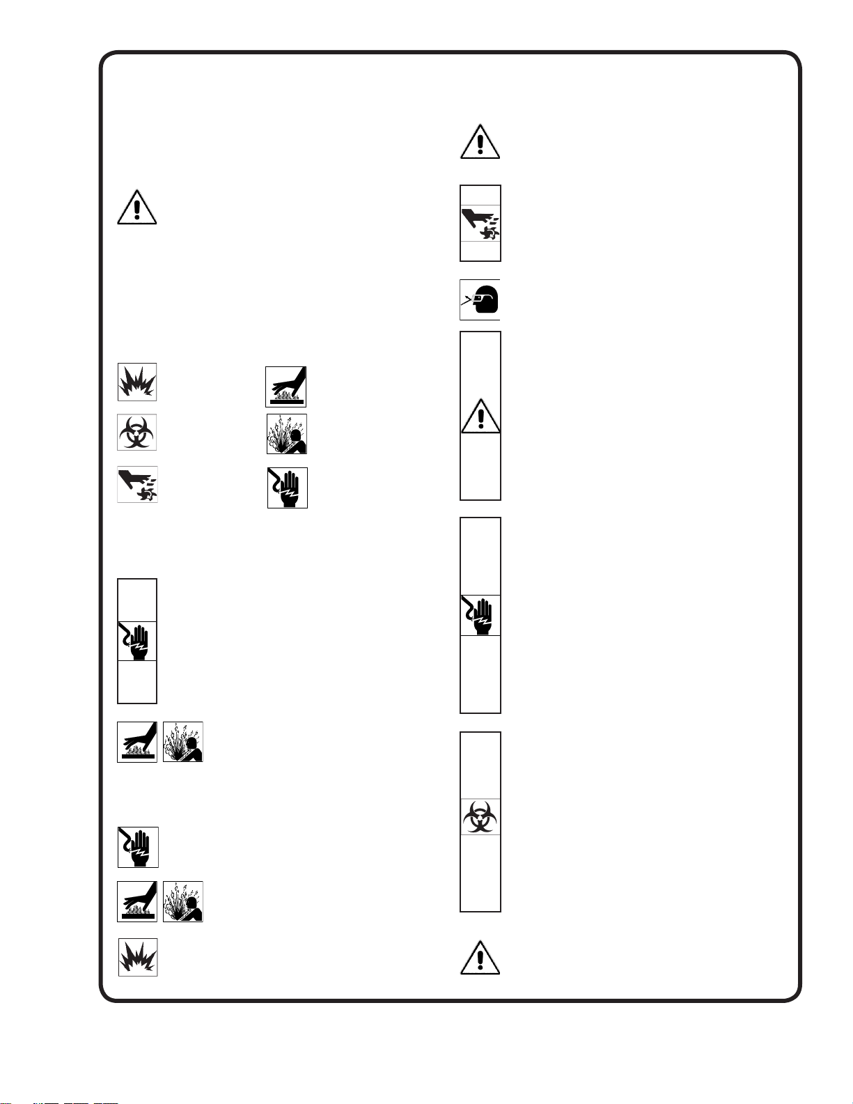
This information is provided for SAFETY and to PREVENT
EQUIPMENT PROBLEMS. To help recognize this information,
observe the following symbols:
IMPORTANT! Warns about hazards that can result
in personal injury orIndicates factors concerned with
assembly, installation, operation, or maintenance which
could result in damage to the machine or equipment if
ignored.
CAUTION! Warns about hazards that can or will cause minor
personal injury or property damage if ignored. Used with symbols
below.
WARNING! Warns about hazards that can or will cause serious
personal injury, death, or major property damage if ignored. Used
with symbols below.
Hazardous fl uids can
cause fi re or explosions, burnes or death
could result.
Biohazard can cause
serious personal injury.
Rotating machinery
Amputation or severe
laceration can result.
Only qualifi ed personnel should install, operate and repair
pump. Any wiring of pumps should be performed by a qualifi ed
electrician.
WARNING ! To reduce risk of electrical shock, pumps and
control panels must be properly grounded in accordance
with the National Electric Code (NEC) or the Canadian
Electrical Code (CEC) and all applicable state, province,
local codes and ordinances. Improper grounding voids
warranty.
WARNING! To reduce risk of electrical shock, always
disconnect the pump from the power source before
handling or servicing. Lock out power and tag.
WARNING! Operation against a closed
discharge valve will cause premature bearing
and seal failure on any pump, and on end
suction and self priming pump the heat build
may cause the generation of steam with resulting dangerous
pressures. It is recommended that a high case temperature
switch or pressure relief valve be installed on the pump body.
CAUTION ! Never operate a pump with a plug-in type
power cord without a ground fault circuit interrupter.
CAUTION ! Pumps build up heat and pressure
during operation-allow time for pumps to cool
before handling or servicing.
WARNING ! Do not pump hazardous materials
(fl ammable, caustic, etc.) unless the pump is specifi cally
designed and designated to handle them.
Extremely hot - Severe
burnes can occur on contact.
Hazardous fl uids can Hazardous pressure, eruptions or explosions could cause personal
injury or property damage.
Hazardous voltage can
shock, burn or cause death.
CAUTION ! Do not block or restrict discharge hose, as
discharge hose may whip under pressure.
WARNING ! Do not wear loose clothing that may
become entangled in moving parts.
WARNING ! Keep clear of suction and discharge
openings. DO NOT insert fi ngers in pump with power
connected.
Always wear eye protection when working on pumps.
Make sure lifting handles are securely fastened each
time before lifting. DO NOT operate pump without safety
devices in place. Always replace safety devices that
have been removed during service or repair. Secure the
pump in its operating position so it can not tip over, fall
or slide.
DO NOT exceed manufacturers recommendation for
maximum performance, as this could cause the motor
to overheat.
DO NOT remove cord and strain relief. DO NOT connect
conduit to pump.
WARNING ! Cable should be protected at all times to
avoid punctures, cut, bruises and abrasions. Inspect
frequently. Never handle connected power cords with
wet hands.
WARNING ! To reduce risk of electrical shock, all wiring
and junction connections should be made per the NEC
or CEC and applicable state or province and local
codes. Requirements may vary depending on usage
and location.
WARNING! Submersible Pumps are not approved for
use in swimming pools, recreational water installations
decorative fountains or any installation where human
contact with the pumped fl uid is common.
WARNING! Products returned must be cleaned,
sanitized, or decontaminated as necessary prior to
shipment, to insure that employees will not be exposed
to health hazards in handling said material. All Applicable
Laws And Regulations Shall Apply.
Bronze/brass and bronze/brass fi tted pumps may
contain lead levels higher than considered safe for
potable water systems. Lead is known to cause cancer
and birth defects or other reproductive harm. Various
government agencies have determined that leaded
copper alloys should not be used in potable water
applications. For non-leaded copper alloy materials of
construction, please contact factory.
Crane Pumps & Systems, Inc. is not responsible for
losses, injury, or death resulting from a failure to observe
these safety precautions, misuse or abuse of pumps or
equipment.
3
Page 4
PUMP SPECIFICATIONS SERIES:
STANDARD SERIES:
DISCHARGE ....................... 2” NPT, Female, Vertical
LIQUID TEMPERATURE:
115 Volt ................................ 77°F (25°C) Continuous
230 Volt................................ 104°F (40°C) Continuous
MOTOR HOUSING ............. Cast Iron ASTM A-48, Class 30
VOLUTE .............................. Cast Iron ASTM A-48, Class 30
(BP-BR) Bronze 81-3-7-9
SEAL PLATE ...................... Cast Iron ASTM A-48, Class 30
(BP-BR) Bronze 81-3-7-9
IMPELLER: Design ............ 2-vane, Open with Pump Out Vanes on
Back Side. Dynamically Balanced,
ISO G6.3
BP314 & BP324 Series:
Material ........... Polypropylene with Stainless Insert
BP314BR & BP324BR Series:
Material ........... Bronze 81-3-7-9
SE411 & SE421 Series:
Material ........... Cast Iron ASTM A-48, Class 30
SE511 & SE521 Series:
Material ........... Cast Iron ASTM A-48, Class 30
IMPELLER - SEV511 & SEV521
Design ............ 12-vane, Open with Pump Out Vanes on
Back Side. Dynamically Balanced,
ISO G6.3
Material ........... Cast Iron ASTM, A-48, Class 30
SHAFT ................................. 416 Stainless Steel
O-RINGS ............................. Buna-N
HARDWARE ....................... 300 Series Stainless Steel
PAINT .................................. Air dry enamel
SEAL Design ............. Single Mechanical, Oil Filled reservoir
Secondary Exclusion Seal
Material ........... Carbon/Ceramic/Buna-N
Hardware - 300 series stainless steel
CORD ENTRY ..................... 15 Ft. (5m) Quick disconnect cord
with plug on 115 volt, pressure
gromment for sealing and strain relief.
UPPER BEARING:
Design ............. Single Row, Ball, Oil Lubricated
Load ................ Radial
LOWER BEARING:
Design ............. Single Row, Ball, Oil Lubricated
Load ................ Radial & Thrust
HIGH TEMPERATURE SERIES:
DISCHARGE .............................2” NPT, Female, Vertical
LIQUID TEMPERATURE ..........200°F (93°C) Continuous
VOLUTE .....................................Cast Iron ASTM A-48, Class 30
MOTOR HOUSING ....................Cast Iron ASTM A-48, Class 30
SEAL PLATE ............................Cast Iron ASTM A-48, Class 30
IMPELLER: Design ................2 Vane, Open with pump out
vanes on back side. Dynamically
Balanced, ISO G6.3
BP314HT & BP324HT Series:
Material .............Bronze 81-3-7-9
SE411HT & SE421HT Series:
Material .............Cast Iron ASTM A-48, Class 30
SHAFT ......................................416 Stainless Steel
SQUARE RINGS .......................Buna-N
HARDWARE ..............................300 Series Stainless Steel
PAINT .........................................Air Dry Enamel
SEAL: Design .............. Single Mechanical, Oil Filled
Reservoir, Secondary Exclusion
Seal
Material ..............Carbon/Ceramic/Buna-N
Hardware -300 Series Stainless
CORD ENTRY ...........................15 ft. (5m) Cord with plug On 115
volt, Pressure Gromment for
sealing and strain relief
UPPER BEARING ......................Single Row, Ball, Oil Lubricated
LOWER BEARING ..................... Single Row, Ball, Oil Lubricated
MOTOR: Design ...............NEMA L Torque Curve, Oil Filled,
Squirrel Cage Induction
Insulation ..........Class B
SINGLE PHASE .........................Permanent Split Capacitor (PSC)
Includes Overload Protection in
Motor
LEVEL CONTROL
A .........................Wide Angle, PVC, Mechanical,
15 ft (5m) cord with Piggy-Back
Plug, N/O
AU ......................Wide Angle, Polypropylene,
Mechanical, N/O Integral to pump.
ON and OFF Points are adjustable
OPTIONAL EQUIPMENT ...........Seal Material, Additional Cord,
Strainer
MOTOR: Design ............. NEMA L Torque Curve. Oil Filled
Squirrel Cage Induction
Insulation ........ Class B
SINGLE PHASE .................. Permanent Split Capacitor (PSC)
Includes Thermal Overload
Protection in motor
LEVEL CONTROLS:
A ...................... Wide Angle, PVC, Mechanical,
15 Ft. (5m) Cord w/Piggy-back plug
N/O, Pipe Mounted
AU ................... Wide Angle, Polypropylene,
Mechanical, N/O, Integral to pump.
ON and OFF Points are Adjustable
VF ................... Vertical Float, PVC, Snap Action,
15 Ft. (5m) Cord w/Piggy-back plug
OFF Point only is Adjustable.
OPTIONAL EQUIPMENT .... Seal Material, Additional Cord,
and Cast Iron Impeller
4
Page 5
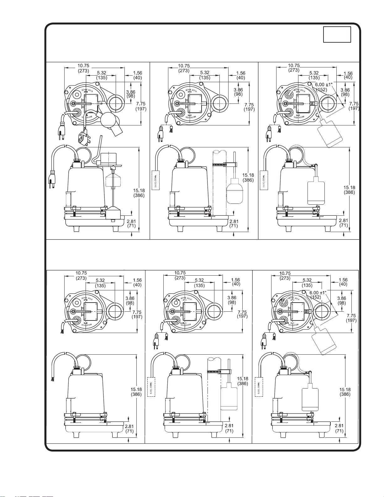
BP314VF, BP314VFBR
SERIES: BP314 & BP324
BP314A, BP314ABR
BP314, BP314BR, BP324, BP324BR (Less Float)
inches
(mm)
BP314AU, BP314AUBR
BP324AU, BP324AUBR
BP314HT, BP314HTBR
BP324HT, BP324HTBR
BP314HTA, BP314HTABR
BP314HTAU, BP314HTAUBR
BP324HTAU, BP324HTAUBR
5
Page 6
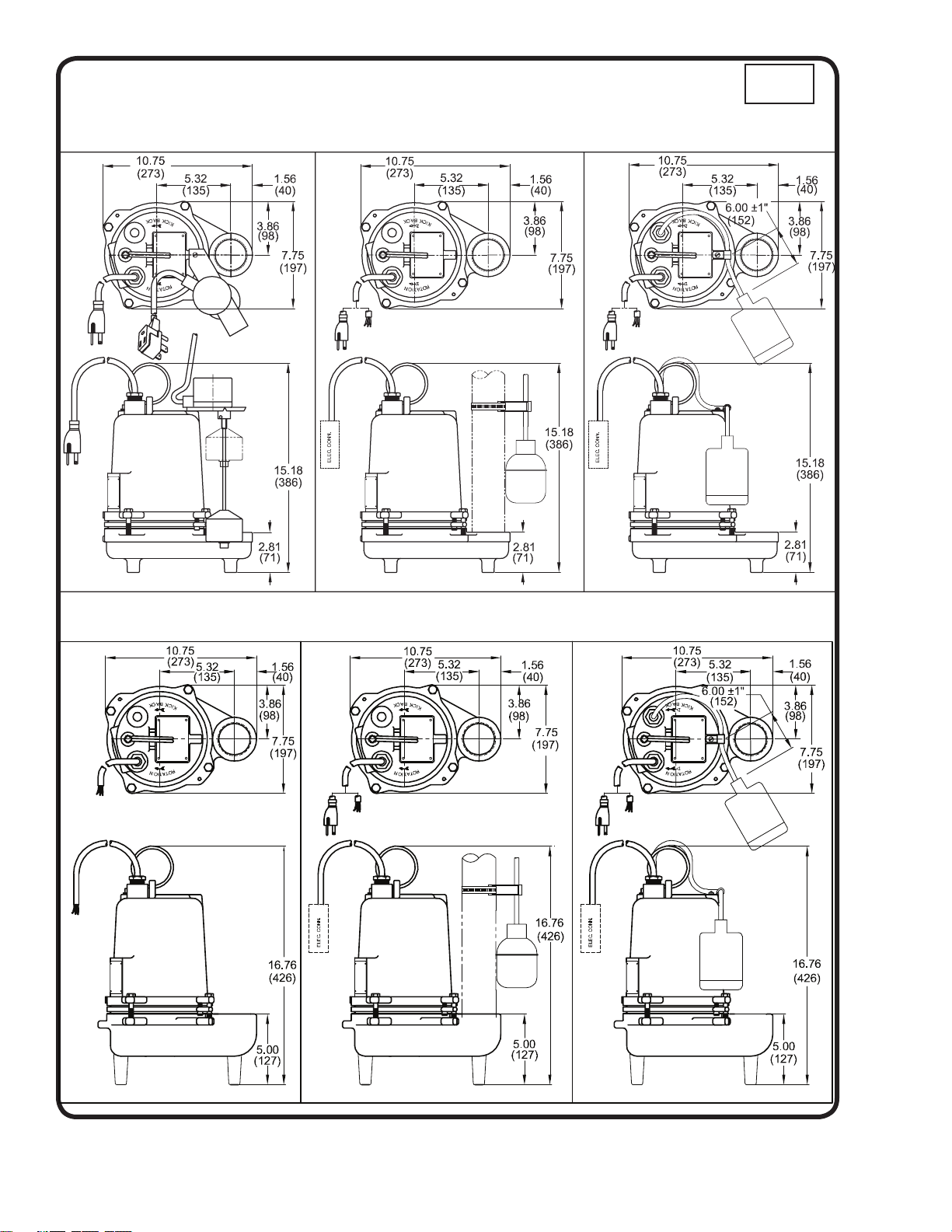
SERIES: SE411, SE421, SE511, SE521, SEV511 & SEV521
SE411VF
SE511VF, SEV511VF
SE411, SE421, SE511, SE521 (Less Float)
SEV511, SEV521 (Less Float)
SE411A, SE511A, SEV511A
inches
(mm)
SE511AU, SE521AU, SEV511AU,
SEV521AU
SE411HT, SE421HT SE411HTA
SE411HTAU, SE421HTAU
6
Page 7

SECTION B: GENERAL INFORMATION
B-1) To The Purchaser:
Congratulations! You are the owner of one of the fi nest
pumps on the market today. Barnes® Pumps are products
engineered and manufactured of high quality components.
Over one hundred years of pump building experience
along with a continuing quality assurance program
combine to produce a pump which will stand up to the
toughest applications.
Check local codes and requirements before installation.
Servicing should be performed by knowledgeable pump
service contractors or authorized service stations.
The pump is packaged ready for installation and no
connections or adjustments are necessary except for
attaching discharge piping and plugging in service cord.
B-2) Receiving:
Upon receiving the pump, it should be inspected for
damage or shortages. If damage has occurred, fi le a claim
immediately with the company that delivered the pump.
If the manual is removed from the crating, do not lose or
misplace.
B-3) Storage:
Short Term- Barnes Pumps are manufactured for effi cient
performance following long inoperative periods in storage.
For best results, pumps can be retained in storage, as
factory assembled, in a dry atmosphere with constant
temperatures for up to six (6) months.
ANSI/NFPA 70 or Canadian Electric Code (CEC). Never
install the pump in a trench, ditch, or hole with a dirt
bottom; the legs will sink into the dirt and the suction will
become plugged.
C-1.1) Submergence:
The pump should always be operated in the submerged
condition. The minimum sump liquid level should never
be less than A Dimension, A = 3 inches on BP Series and
A = 6 inches on SE Series above the pump bottom. The
recommended level should not drop below the top of the
motor housing (see Fig. 1).
Long Term- Any length of time exceeding six (6) months,
but not more than twenty four (24) months. The units
should be stored in a temperature controlled area, a roofed
over walled enclosure that provides protection from the
elements (rain, snow, wind blown dust, etc..), and whose
temperature can be maintained between +40 deg. F and
+120 deg. F. Pump should be stored in its original shipping
container and before initial start up, rotate impeller by hand
to assure seal and impeller rotate freely.
B-4) Service Centers:
For the location of the nearest Barnes Service Center, check
your Barnes representative or Crane Pumps & Systems, Inc.,
Service Department in Piqua, Ohio, telephone (937) 778-8947
or Crane Pumps & Systems Canada, Inc., Bramton, Ontario,
(905) 457-6223.
SECTION C: INSTALLATION
C-1) Location:
These pumping units are self-contained and are
recommended for use in a sump or basin. The sump or
basin shall be vented in accordance with local plumbing
codes. This pump is designed to pump effl uent or
wastewater, nonexplosive and noncorrosive liquids and
shall NOT be installed in locations classifi ed as hazardous
in accordance with the National Electrical Code (NEC),
FIGURE 1
C-2) Discharge:
Discharge piping should be as short as possible. Both a
check valve and a shut-off valve are recommended for
each pump being used. The check valve is used to prevent
backfl ow into the sump. Excessive backfl ow can cause
fl ooding and/or damage to the pump. The shut-off valve
is used to stop system fl ow during pump or check valve
servicing.
Barnes Pumps supplies a Stainless Rail Package and also
a variety of break-away fi tting discharge systems designed
to allow the submersible wastewater pump to be installed
or removed without requiring personnel to enter the wet
well. Contact your local Barnes Pumps distributor for
complete details.
C-3) Liquid Level Controls:
Figure 2 shows a typical installation for any submersible
pump using a level control mounted to the discharge piping
with a piggy-back plug.
7
Page 8
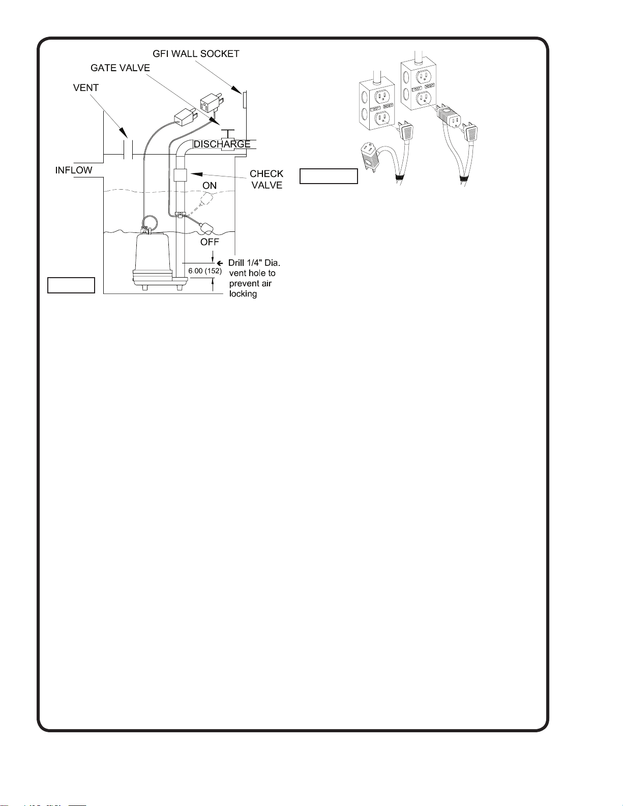
FIGURE 2
General Comments:
1) Never work in the sump with the power on.
2) Level controls are factory set for a pumping differential
of 9 inches. If that is the cycle desired, simply circle
the discharge pipe with the pipe mounting strap, feed
the end through the worm drive, and tighten with a
screwdriver. Be certain that the level control cannot
hang up or foul in its swing. Also, make certain the
pump impeller is still submerged when the level control
is in the “OFF” mode.
3) If a higher pump differential is needed, grip the cord
near the neck of the fl oat, then using the other hand,
exert a steady force on the lower edge of the cable
clamp. The cable clamp should slide up to the new
pivot point. Attach the level control to the discharge
hose in the manner described above.
4) Plug the level control plug into the GFI receptacle,
then plug the pump into the piggyback plug. One cycle
of operation should be observed, so that any potential
problems can be corrected.
5) It is recommended that the fl oat should be set to
insure that the sump well liquid level never drops
below the top of the motor housing or a minimum level
of 3 inches on BP Series and 6 inches on SE Series
above the pump bottom.
Manual
FIGURE 3
Automatic
Automatic - Plug fl oat cord into GFI outlet, then plug pump
cord into fl oat cord.
Manual - Plug pump cord directly into GFI outlet.
C-4) Electrical Connections:
C-4.1) Power Cable:
The cord assembly mounted to the pump must not be
modifi ed in any way except for shortening to a specifi c
application. Any splice between the pump and the control
panel must be made in accordance with the electric codes.
It is recommended that a junction box, if used, be mounted
outside the sump or be of at least NEMA 4 (EEMAC-4)
construction if located within the wet well. Do not use the
power cable to lift pump. NOTE: THE WHITE WIRE IS
NOT A NEUTRAL OR GROUND LEAD, BUT A POWER
CARRYING CONDUCTOR.
C-4.2) Overload Protection:
Single Phase - The type of in-winding overload protector
used is referred to as an inherent overheating protector
and operates on the combined effect of temperature and
current. This means that the overload protector will trip out
and shut the pump off if the windings become too hot, or
the load current passing through them becomes too high.
It will then automatically reset and start the pump up
after the motor cools to a safe temperature. In the event
of an overload, the source of this condition should be
determined and rectifi ed immediately. DO NOT LET THE
PUMP CYCLE OR RUN IF AN OVERLOAD CONDITION
OCCURS !
C-4.3) Wire Size:
Consult a qualifi ed electrician for proper wire size. See
table for electrical information.
6.) Figure 3 shows a typical connection for pumps with the
wide angle fl oat and piggy-back plug, for manual and
automatic operations.
8
Page 9
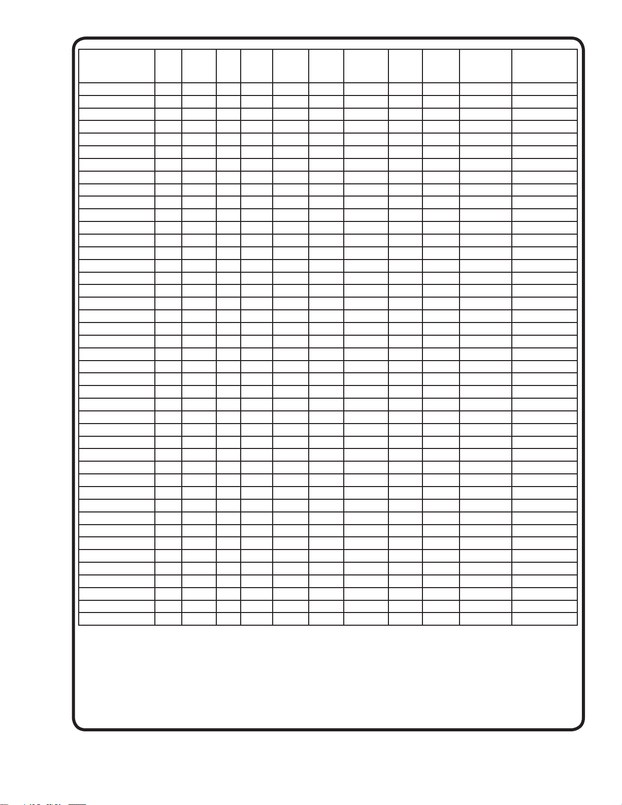
MODEL NO HP VOLT/PHHz RPM
(Nom)
BP314 1/3 115/1 60 1750 A 8.0 19.0 14/3 SJTOW 0.375 (9.5) 2.14 - 30.5
BP314A 1/3 115/1 60 1750 A 8.0 19.0 14/3 SJTOW 0.375 (9.5) 2.14 - 30.5
BP314AU 1/3 115/1 60 1750 A 8.0 19.0 14/3 SJTOW 0.375 (9.5) 2.14 - 30.5
BP314VF 1/3 115/1 60 1750 A 8.0 19.0 14/3 SJTOW 0.375 (9.5) 2.14 - 30.5
BP314BR 1/3 115/1 60 1750 A 8.0 19.0 14/3 SJTOW 0.375 (9.5) 2.14 - 30.5
BP314ABR 1/3 115/1 60 1750 A 8.0 19.0 14/3 SJTOW 0.375 (9.5) 2.14 - 30.5
BP314AUBR 1/3 115/1 60 1750 A 8.0 19.0 14/3 SJTOW 0.375 (9.5) 2.14 - 30.5
BP314VFBR 1/3 115/1 60 1750 A 8.0 19.0 14/3 SJTOW 0.375 (9.5) 2.14 - 30.5
BP324 1/3 230/1 60 1750 A 4.0 13.0 14/3 SJTOW 0.375 (9.5) 5.45 - 16.7
BP324AU 1/3 230/1 60 1750 A 4.0 13.0 14/3 SJTOW 0.375 (9.5) 5.45 - 16.7
BP324BR 1/3 230/1 60 1750 A 4.0 13.0 14/3 SJTOW 0.375 (9.5) 5.45 - 16.7
BP324AUBR 1/3 230/1 60 1750 A 4.0 13.0 14/3 SJTOW 0.375 (9.5) 5.45 - 16.7
BP314HT 1/3 115/1 60 1750 A 8.0 19.0 14/3 SOOW 0.560 (14.2) 2.14 - 30.5
BP314HTA 1/3 115/1 60 1750 A 8.0 19.0 14/3 SOOW 0.560 (14.2) 2.14 - 30.5
BP314HTAU 1/3 115/1 60 1750 A 8.0 19.0 14/3 SOOW 0.560 (14.2) 2.14 - 30.5
BP314HTBR 1/3 115/1 60 1750 A 8.0 19.0 14/3 SOOW 0.560 (14.2) 2.14 - 30.5
BP314HTABR 1/3 115/1 60 1750 A 8.0 19.0 14/3 SOOW 0.560 (14.2) 2.14 - 30.5
BP314HTAUBR 1/3 115/1 60 1750 A 8.0 19.0 14/3 SOOW 0.560 (14.2) 2.14 - 30.5
BP324HT 1/3 230/1 60 1750 A 4.0 13.0 14/3 SOOW 0.560 (14.2) 5.45 - 16.7
BP324HTAU 1/3 230/1 60 1750 A 4.0 13.0 14/3 SOOW 0.560 (14.2) 5.45 - 16.7
BP324HTBR 1/3 230/1 60 1750 A 4.0 13.0 14/3 SOOW 0.560 (14.2) 5.45 - 16.7
BP324HTAUBR 1/3 230/1 60 1750 A 4.0 13.0 14/3 SOOW 0.560 (14.2) 5.45 - 16.7
SE411 0.4 115/1 60 1750 C 12.0 19.0 16/3 SJTOW 0.310 (7.9) 2.14 - 30.5
SE411A 0.4 115/1 60 1750 C 12.0 19.0 16/3 SJTOW 0.310 (7.9) 2.14 - 30.5
SE411VF 0.4 115/1 60 1750 C 12.0 19.0 16/3 SJTOW 0.310 (7.9) 2.14 - 30.5
SE421 0.4 230/1 60 1750 C 6.2 13.0 14/3 SJTOW 0.375 (9.5) 5.45 - 16.7
SE411HT 0.4 115/1 60 1750 A 10.0 26.0 14/3 SOOW 0.560 (14.2) 1.37 - 15.2
SE411HTA 0.4 115/1 60 1750 A 10.0 26.0 14/3 SOOW 0.560 (14.2) 1.37 - 15.2
SE411HTAU 0.4 115/1 60 1750 A 10.0 26.0 14/3 SOOW 0.560 (14.2) 1.37 - 15.2
SE421HT 0.4 230/1 60 1750 A 4.0 13.0 14/3 SOOW 0.560 (14.2) 5.45 - 16.7
SE421HTAU 0.4 230/1 60 1750 A 4.0 13.0 14/3 SOOW 0.560 (14.2) 5.45 - 16.7
SE511 0.5 115/1 60 1750 A 12.0 26.0 14/3 SJTOW 0.375 (9.5) 1.37 - 15.2
SE511A 0.5 115/1 60 1750 A 12.0 26.0 14/3 SJTOW 0.375 (9.5) 1.37 - 15.2
SE511AU 0.5 115/1 60 1750 A 12.0 26.0 14/3 SJTOW 0.375 (9.5) 1.37 - 15.2
SE511VF 0.5 115/1 60 1750 A 12.0 26.0 14/3 SJTOW 0.375 (9.5) 1.37 - 15.2
SE521 0.5 230/1 60 1750 A 6.2 13.0 14/3 SJTOW 0.375 (9.5) 5.45 - 16.7
SE521AU 0.5 230/1 60 1750 A 6.2 13.0 14/3 SJTOW 0.375 (9.5) 5.45 - 16.7
SEV511 0.5 115/1 60 1750 A 12.0 26.0 14/3 SJTOW 0.375 (9.5) 1.37 - 15.2
SEV511A 0.5 115/1 60 1750 A 12.0 26.0 14/3 SJTOW 0.375 (9.5) 1.37 - 15.2
SEV511AU 0.5 115/1 60 1750 A 12.0 26.0 14/3 SJTOW 0.375 (9.5) 1.37 - 15.2
SEV511VF 0.5 115/1 60 1750 A 12.0 26.0 14/3 SJTOW 0.375 (9.5) 1.37 - 15.2
SEV521 0.5 230/1 60 1750 A 6.2 13.0 14/3 SJTOW 0.375 (9.5) 5.45 - 16.7
SEV521AU 0.5 230/1 60 1750 A 6.2 13.0 14/3 SJTOW 0.375 (9.5) 5.45 - 16.7
NEMA
START
CODE
FULL
LOAD
AMPS
LOCKED
ROTOR
AMPS
CORD
SIZE
CORD
TYPE
CORD
O.D
inch (mm)
WINDING
RESISTANCE
MAIN - START
Winding Resistance ± 5%. Pump rated for operation at ± 10% voltage at motor.
Mechanical Switch on A, cord 16/2, SJOW, Piggy-Back Plug.
Mechanical Switch on AU, cord 14/2, SJOW
Vertical Switch on VF, cord 16/2, SJOW, Piggy-Back Plug
Mechanical Switch on HTA, cord 14/2, SJOOW, 0.370 (9.4MM) O.D., Piggy-Back Plug.
Mechanical Switch on HTAU, cord 14/2, SJOOW, 0.370 (9.4MM) O.D.
9
Page 10

SECTION: D START-UP OPERATION
D-1) Check Voltage and Phase:
Before operating pump check to make sure that the
voltage and phase information stamped on the pump’s
identifi cation plate matches the available power.
D-2) Check Pump Rotation:
Before putting pump into service for the fi rst time, the
motor rotation must be checked. Improper motor rotation
can result in poor pump performance and can damage
the motor and/or pump. To check the rotation, suspend
the pump freely, momentarily apply power and observe
the “kickback”. “Kickback” should always be in a counterclockwise direction as viewed from the top of the pump
(“kickback” is always opposite to impeller rotation).
“Rotation” and “kickback” direction is noted on the pump
motor housing.
1) Inspect motor chamber for oil level and contamination
and repair as required per section F-1.
2) Inspect impeller and body for excessive build-up or
clogging and repair as required per section F-2.
3) Inspect bearing and replace as required per section F-3.
4) Inspect seal for wear or leakage and repair as required
per section F-4.
SECTION F: SERVICE AND REPAIR
NOTE: All item numbers ( ) refer to Figures 14 & 15, for
BP Series, 16 & 17 for SE series and 18 & 19 for SEV
series.
F-1) Lubrication:
Anytime the pump is removed from operation and at least
every twelve (12) months, the cooling oil in the motor
housing (12) must be checked visually for oil level and
contamination.
D-2.1) Incorrect Rotation for Single-Phase:
In the unlikely event that the rotation is incorrect for a
single-phase pump, contact a Barnes Pumps Service
Center.
D-3) Identifi cation Plate:
Record the numbers off the pump’s identifi cation plate
onto the START-UP REPORT provided at the end of the
manual for future reference.
D-4) Start-Up Report:
Included at the end of this manual are two start-up report
sheets. These sheets are to be completed as applicable.
Return one copy to Barnes Pumps and store the second
in the control panel or with the pump manual if no
control panel is used. It is important to record this data at
initial start-up since it will be useful to compare to when
servicing the pump in the future.
Insulation Test:
Before the pump is put into service, an insulation (megger)
test should be performed on it. The ohm values as well
as the volts and amps should be recorded on the start-up
sheet and stored safely in the control panel or with the
pump manual if no control panel is used.
Pump-Down Test:
After the pump has been properly wired and lowered into
the basin, sump, or lift station, it is advisable to check
the system by fi lling with liquid and allowing the pump
to operate through its pumping cycle. The time needed
to empty the system, or pump-down time, should be
recorded on the start-up sheet.
F-1.1) Checking Oil:
To check oil, set unit upright. Remove pipe plug (24). With
a fl ashlight, visually inspect the oil in the motor housing
(14) to make sure it is clean, clear and that the oil level is
above all internal componentry. If oil appears satisfactory,
replace pipe plug. If oil is low or appears contaminated,
test oil as per section F-1.2
F-1.2) Testing Oil:
1. Place pump on it’s side, remove pipe plug (24) and
drain oil into a clean, dry container.
2. Check oil for contamination using an oil tester with a
range to 30 kilovolts breakdown.
3. If oil is found to be clean and uncontaminated
(measures above 15 KV. breakdown), refi ll the motor
housing as per section F-1.3.
4. If oil is found to be dirty or contaminated (or measures
below 15KV. breakdown), then the pump must be
carefully inspected for leaks at the shaft seal (3),
cord inlet (9), o-ring (13), and pipe plug (24)
before refi lling with oil. To locate the leak, perform a
pressure test as per section F-1.4. After leak is
repaired, refi ll with new oil as per section F-1.3.
F-1.3 Replacing Oil in Motor Housing:
Drain all oil from motor housing and dispose of properly.
Refi ll with 58 ounces of new cooling oil as per Table 1. An
air space must remain in the top of the motor housing to
compensate for air expansion. Set unit upright and fi ll only
until oil level from top of pipe plug boss is 3” ± 1/4”.
When refi lling with oil after servicing the shaft seal (3), a
pressure test as per section F-1.4 should be done. If shaft
seal was not disturbed during service, then apply pipe
sealant and replace the pipe plug (24).
SECTION E: PREVENTATIVE MAINTENANCE
As the motor is oil fi lled, no lubrication or other
maintenance is required, and generally Barnes pumps will
give very reliable service and can be expected to operate
for years on normal sewage pumping without failure.
However, as with any mechanical piece of equipment a
preventive maintenance program is recommended and
suggested to include the following checks:
WARNING ! - DO NOT overfi ll oil. Overfi lling of
motor housing with oil can create excessive
and dangerous hydraulic pressure which
can destroy the pump and create a hazard.
Overfi lling oil voids warranty.
10
Page 11
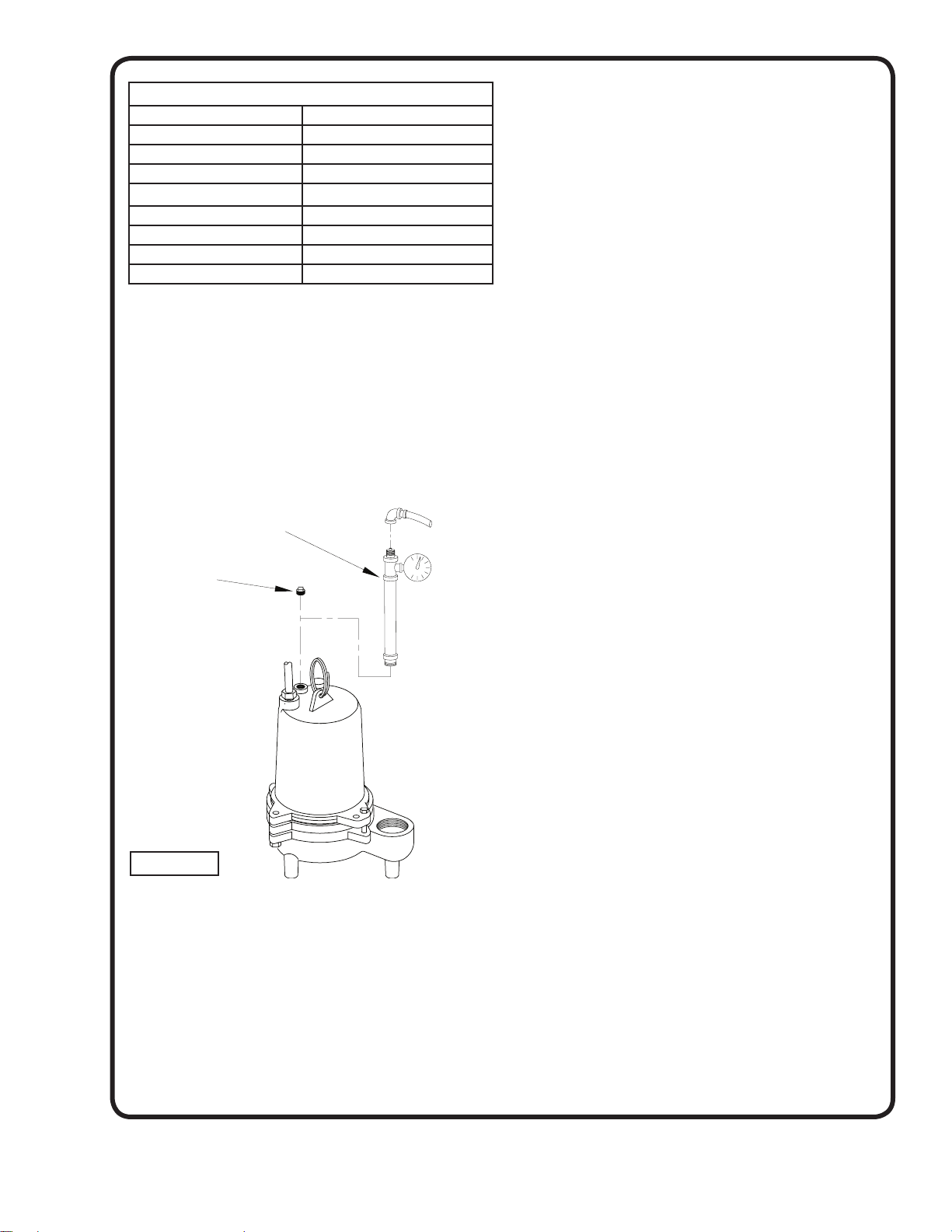
TABLE 1 - COOLING OIL - Dielectric
SUPPLIER GRADE
BP Enerpar SE100
Conoco Pale Paraffi n 22
Mobile D.T.E. Oil Light
G & G Oil Circulating 22
Imperial Oil Voltesso-35
Shell Canada Transformer-10
Texaco Diala-Oil-AX
Woco Premium 100
F-1.4) Pressure Test:
Before checking the pump for leaks around the shaft
seal, square ring, and cord inlet, the oil level should be
full as described in section F1.3. Apply pipe sealant to the
pressure gauge assembly and tighten into fi ll plug hole
(see fi g.4). Pressurize motor housing to 10 P.S.I. Use a
soap solution around the sealed areas and inspect joints
for “air bubbles”. If, after fi ve minutes, the pressure is still
holding constant, and no “bubbles” are observed, slowly
bleed the pressure and remove the gauge assembly.
Replace the pipe plug using a sealant. If the pressure
does not hold, then the leak must be located.
Pressure Gauge Assembly
(See Parts List)
Remove Pipe
Plug
ç 10 PSI
AIR
F-2.2) Reassembly:
Before installing impeller (17), inspect threads on shaft
and impeller to assure that they are clean. Place exclusion seal on shaft with the thin lip toward the motor (see
section F-4.3). Apply a thread-locking compound to shaft
threads and screw impeller onto shaft and tighten. Rotate
impeller to check for binding. Position gasket (19) on body
and install impeller and motor housing on pump body.
Apply thread locking compound to each cap screw (21),
thread into body, and torque to 11 ft. lbs. Check for free
rotation of impeller.
F-3) Motor, Bearing and Cable Service
F-3.1) Disassembly and Inspection:
BP & SE Series, Motor - To examine or replace the mo-
tor (1) or bearing (4), remove body and impeller as per
section F-2.1. Drain oil from motor housing as per section
F-1.2. Remove gland nut (9a) and friction ring (9b) from
motor housing (14). Pull cord through opening and disconnect the motor wires from the terminals on cable (9), see
Figure 5. Remove socket head screws (15) and lift motor
housing (14) from seal plate (2). Remove o-ring (13) and
inspect for breaks. Loosen motor screws and pull motor
(1) straight up and off seal plate (2). Inspect all parts for
signs of wear and check motor resistance values.
On “AU” series pumps gland nut (29a) and friction ring
(29b) must also be removed from motor housing (14) and
pulled though opening and motor wires from the terminals
on cable (2), see Figure 5.
FIGURE 4
F-2) Impeller and Volute Service:
F-2.1) Disassembly and Inspection:
To clean out body (20), or to replace impeller (17),
disconnect power, remove hex bolts (21), and vertically lift
motor and seal assembly from body (20). Clean out body
if necessary . Clean and examine impeller (17) for pitting
or wear and replace if required. Inspect gasket (19) and
replace if cut or damaged. The impeller (17) is threaded
onto the shaft and to remove, unscrew impeller, holding
shaft with a large screwdriver. Remove exclusion seal (16)
and replace if needed.
BP-HT & SE-HT Series, Motor - To examine or replace
the motor (1) or bearing (4), remove body and impeller
as per section F-2.1. Drain oil from motor housing as
per section F-1.2. Remove socket head screws (15) and
loosen gland nut (9a) and push cord through while lifting
motor housing (14) off of seal plate (2). Disconnect motor
wires from cord set (9). Pull cord through motor housing
along with two friction rings and one gromment. (See
Figure 6). Remove o-ring (13) and inspect for breaks.
Loosen motor screws and pull motor (1) straight up and
off seal plate (2). Inspect all parts for signs of wear and
check motor resistance values.
On “HTAU” series pumps gland nut (29a), must also be
loosened from motor housing (14). Push cord through
while lifting motor housing (14) off of seal plate (2).
Disconnect motor wires from cord set (29). Pull cord
through motor housing along with friction rings (29b) and
grommet (29c), see Figure 6.
Check capacitor (7) with an Ohm meter by grounding the
capacitor by placing a screwdriver across both terminals
and then removing the screwdriver. Connect Ohm meter
(set on high scale) to terminals, if needle moves to infi nity
( ∞ ) then drifts back, the capacitor is good. If needle does
not move or moves to infi nity ( ∞ ) and does not drift back,
replace capacitor (7).
11
Page 12
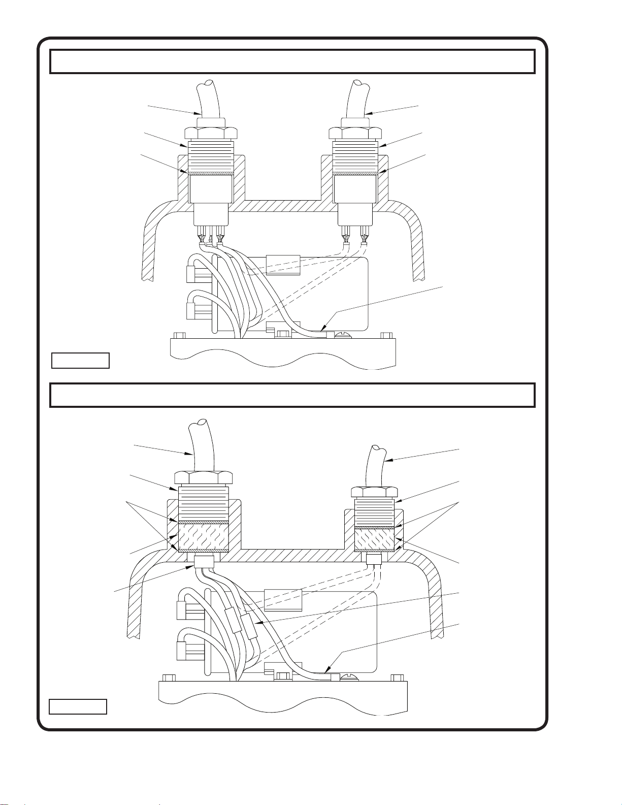
STANDARD CONNECTIONS
CORD SET (29) IS FOR “AU” MODEL ONLY
CORD SET (9)
GLAND NUT (9A)
FRICTION RING (9B)
FIGURE 5
CORD SET FOR HIGH TEMPERATURE MODELS ONLY
CORD SET (29)
GLAND NUT (29A)
FRICTION RING (29B)
GREEN - GROUND
CORD SET (9)
GLAND NUT (9A)
FRICTION RING (9B)
GROMMET (9C)
EPOXY SEALER
FIGURE 6
CORD SET (29) IS FOR “AU” MODEL ONLY
CORD SET (29)
GLAND NUT (29A)
FRICTION RING (29B)
GROMMET (29C)
CONNECTORS (45)
GREEN - GROUND
12
Page 13
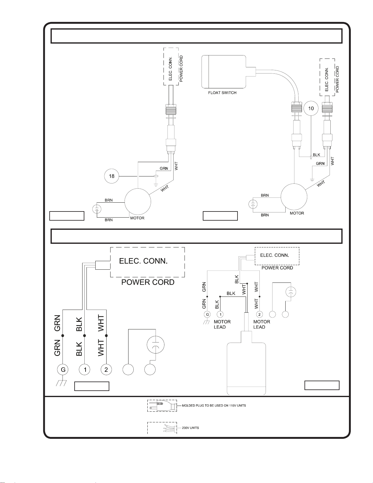
STANDARD CONNECTIONS
FIGURE 7 FIGURE 8
CORD SET FOR HIGH TEMPERATURE MODELS ONLY
FIGURE 9
FIGURE 10
Electrical Connections:
13
Page 14
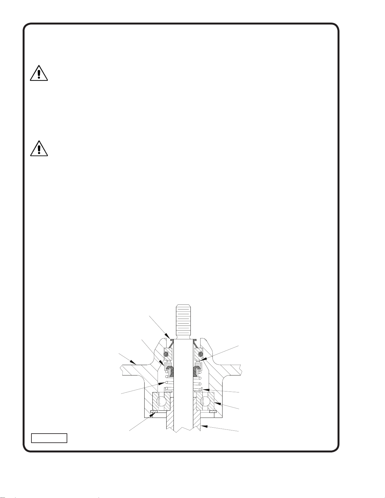
Bearings - Disassemble motor as per section F-3.1.
Remove snap ring (6) with snap ring pliers and pull motor
(1) and lower bearing (4) straight off of seal plate (2).
Inspect all parts for signs of wear and replace as needed.
CAUTION! Handle seal parts with extreme care.
do not scratch or mar lapped surfaces.
F-3.2) Replacing Bearing:
When replacing bearing, be careful to not damage the
rotor or shaft threads. Press the old bearing off the
shaft with an arbor press or gear puller. Clean the shaft
thoroughly. Apply adhesive compound to shaft and press
new bearing on, pushing only on the inner race, until it
seats against shoulder of shaft (see fi g.12).
IMPORTANT! - All parts must be clean before
reassembly.
F-3.3) Reassembly:
Make sure shaft seal (3) is clean and in proper position as
per section F-4.2 before reassembling rotor and bearing.
Slide lower bearing and rotor shaft squarely into the seal
plate (2) until bearing seats on the bottom. Insert snap
ring (6) into seal plate with fl at edge against outer race of
bearing. Place motor stator squarely onto seal plate (2)
and tighten motor screws. Install o-ring (13) onto seal plate
(2).
On BP & SE Series, slip motor wires through opening in
motor housing (14) see Figure 5. Connect motor wires to
cord set as per Figure 7. Place friction ring (9b) and gland
nut (9a) into motor housing (14) and tighten gland nut to
17.5 ft. lbs. On “AU” series pumps slip fl oat wires through
opening in motor housing (14) and connect to fl oat cable
(29) see Figure 8. Place friction ring (29b) and gland nut
(29a) into motor housing (14) and tighten gland nut to 17.5
ft. lbs.
PUMP
(Outboard End)
Place motor housing (14) squarely onto seal plate (2).
Tighten socket head screws (15) into motor housing. Refi ll
with cooling oil as per paragraph F-1.3.
On BP-HT & SE-HT Series, slide the gland nut, friction
rings and grommet onto cord set (see Figure 6) and slip
cord through motor housing (14). Connect motor wires
per Figure 9. Place motor housing (14) squarely onto
seal plate while pulling excess cord through hole. Tighten
socket head screws (15) into motor housing. Slide the
friction rings (9b), grommet (9c) and gland nut (9a) into
motor housing and tighten gland nut to 17.5 ft. lbs. Refi ll
with cooling oil as per paragraph F-1.3. On “HTAU” series
pumps slide the gland nut, friction rings and grommet onto
cord set (see Figure 6) and slip cord (29) through motor
housing (14). Connect wires per Figure 10.
F-4) Shaft Seal Service
F-4.1) Dissassembly and Inspection:
Disassemble pump motor as per section F-3.1. Inspect
seal for signs of wear such as uneven wear pattern on
the stationary member or chips and scratches on either
sealing face. Do not interchange seal components.
Replace entire seal if damage occurs.
F-4.2) Replacing Shaft Seal (refer to fi g. 11, 12 & 13):
When replacing the shaft seal (3), remove used rotating
member (3c), spring (3b), and spring retainer (3a) from
motor shaft. Press used stationary member (3d) from the
seal plate (2). At reassembly, clean seal cavity thoroughly
and apply a light coat of oil. Lightly oil the rubber ring (DO
NOT use grease) and press the stationary member fi rmly
into the seal plate using a seal pusher (See Parts ListSeal Tool Kit), nothing but pusher to come in contact with
seal face (see Fig. 11). Insert so that the fi nished surface
is up and the grooved surface is against the seal plate.
Make sure the stationary member is in straight and that the
rubber ring is not out of it’s groove.
END
FIGURE 12
Exclusion Seal
Rotating Member (3c)
Seal Plate
Spring (3b)
Retaining Ring (6)
Stationary (3d)
Polished Mating Surface
Retaining Ring (3a)
Bearing (4)
Sleeve (27)
MOTOR END
(Inboard End)
14
Page 15
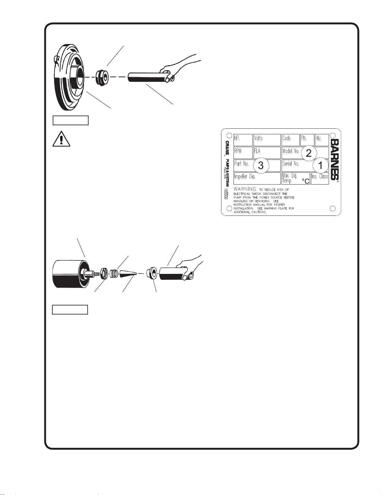
Stationary Member
(3d) Polished Face Out
Seal Pusher
Seal Plate
FIGURE 11
DO NOT HAMMER ON THE SEAL PUSHER - IT
WILL DAMAGE THE SEAL FACE.
Place spring retainer and spring onto motor shaft. Lightly
oil shaft (DO NOT use grease) and inner surface of
bellows of rotating member. With fi nished end away from
motor, slide rotating member over bullet and onto shaft
until it engages spring (see Fig. 13). Carefully assemble
shaft to seal plate as per section F-3.3. It is extremely
important to keep seal faces clean during assembly. Dirt
particles lodged between these faces will cause the seal
to leak. When seal plate is assembled to motor, it will
properly align and seat the seal (3) and bearing (4). Follow
complete reassembly instructions as per section F-3.3.
Motor, Sleeve &
Bearing
Seal Pusher
Spring
SECTION: G REPLACEMENT PARTS
G-1 ORDERING REPLACEMENT PARTS:
When ordering replacement parts, ALWAYS furnish the
following information:
1. Pump serial number and date code. (Paragraph G-4)
2. Pump model number. (Paragraph G-3)
3. Pump part number. (Paragraph G-2)
4. Part description.
5. Item part number.
6. Quantity required.
7. Shipping instructions.
8. Billing Instructions.
G-2 PART NUMBER:
The part number consists of a six (6) digit number, which
appears in the catalog. A one or two letter suffi x may follow
this number to designate the design confi guration. This
number is used for ordering and obtaining information.
Retaining Ring (3a)
FIGURE 13
Bullet
Rotating Member (3c)
F-4.3) Replacing Exclusion Seal:
The exclusion seal (16), helps to keep debris away from
the shaft seal where it could cause damage. The exclusion
seal should be replaced whenever the shaft seal is
replaced. To replace the exclusion seal, pull the old seal off
the shaft, and slide the new seal on with the thin lip toward
the motor. Be sure not to damage the lip of the seal. Finger
pressure is all that is needed to install the exclusion seal.
G-3 MODEL NUMBER:
This designation consists of numbers and letters which
represent the discharge size, series, horsepower, motor
phase and voltage, speed and pump design. This number is
used for ordering and obtaining information.
G-4 SERIAL NUMBER:
The serial number block will consist of a six digit number,
which is specifi c to each pump and may be preceded by
an alpha character, which indicates the plant location.
This number will also be suffi xed with a four digit number,
which indicates the date the unit was built (Date Code).
EXAMPLE: A012345 0490.
Reference the six digit portion (Serial Number) of this
number when referring to the product.
15
Page 16
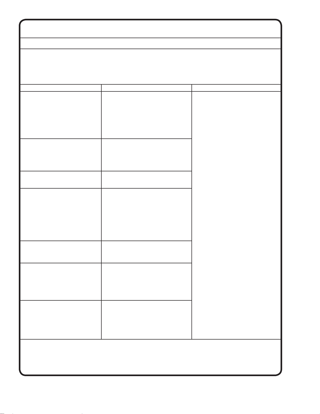
TROUBLE SHOOTING
CAUTION ! Always disconnect the pump from the electrical power source before handling.
If the system fails to operate properly, carefully read instructions and perform maintenance recommendations.
If operating problems persist, the following chart may be of assistance in identifying and correcting them:
MATCH “CAUSE” NUMBER WITH CORRELATING “CORRECTION” NUMBER.
NOTE: Not all problems and corrections will apply to each pump model.
PROBLEM C
Pump will not run 1. Poor electrical connection, blown fuse,
Pump will not turn off 2a. Float movement restricted.
Pump hums but does not run 1. Incorrect voltage
Pump delivers insuffi cient capacity 1. Incorrect voltage.
Pump cycles too frequently or runs
periodically when fi xtures are not in use
Pump shuts off and turns on independent of switch, (trips thermal overload
protector). CAUTION! Pump may start
unexpectedly. Disconnect power supply.
Pump operates noisily or vibrates
excessively
tripped breaker or other interruption of power,
improper power supply.
2. Motor or switch inoperative (to isolate
cause, go to manual operation of pump).
2a. Float movement restricted.
2b. Switch will not activate pump or is defective.
2c. Defective motor
3. Insuffi cient liquid level.
2b. Switch will not activate pump or is defective.
4. Excessive infl ow or pump not properly sized
for application.
9. Pump may be airlocked
14. H-O-A switch on panel is in “HAND” position
8. Impeller jammed or loose on shaft, worn or
damaged, impeller cavity or inlet plugged.
4. Excessive infl ow or pump not properly sized
for application.
5. Discharge restricted.
6. Check valve stuck closed or installed backwards.
7. Shut-off valve closed.
8. Impeller jammed or loose on shaft, worn or
damaged, impeller cavity or inlet plugged.
9. Pump may be airlocked.
10. Pump running backwards
6. Check valve stuck closed or installed
backwards.
11. Fixtures are leaking.
15. Ground water entering basin.
1. Incorrect voltage.
4. Excessive infl ow or pump not properly sized
for application.
8. Impeller jammed, loose on shaft, worn or
damaged, impeller cavity or inlet plugged.
12. Excessive water temperature.
(internal protection only)
2c. Worn bearings, motor shaft bent.
8. Debris in impeller cavity or broken impeller
10. Pump running backwards
13. Piping attachments to buiding structure too
rigid or too loose.
AUSE CORRECTION
1. Check all electrical connections for
security. Have electrician measure current
in motor leads, if current is within ±20%
of locked rotor Amps, impeller is probably
locked. If current is 0, overload may be
tripped. Remove power, allow pump to cool,
then recheck current.
2a. Reposition pump or clean basin as
required to provide adequate clearance for
fl oat.
2b. Disconnect level control. Set ohmmeter
for a low range, such as 100 ohms full scale
and connect to level control leads. Actuate
level control manually and check to see that
ohmmeter shows zero ohms for closed switch
and full scale for open switch. (Float Switch).
2c. Check winding insulation (Megger Test)
and winding resistance. If check is outside
of range, dry and recheck. If still defective,
replace per service instructions.
3. Make sure liquid level is at least equal to
suggested turn-on point.
4. Recheck all sizing calculations to
determine proper pump size.
5. Check discharge line for restrictions,
including ice if line passes through or into
cold areas.
6. Remove and examine check valve for
proper installation and freedom of operation.
7. Open valve.
8. Check impeller for freedom of operation,
security and condition. Clean impeller and
inlet of any obstruction.
9. Loosen union slightly to allow trapped air
to escape.Verify that turn-off level of switch
is set so that the suction is always fl ooded.
Clean vent hole.
10. Check rotation. If power supply is three
phase, reverse any two of three power supply
leads to ensure proper impeller rotation..
11. Repair fi xtures as required to eliminate
leakage.
12. Check pump temperature limits & fl uid
temperature.
13. Replace portion of discharge pipe with
fl exible connector.
14. Turn to automatic position.
15. Check for leaks around basin inlet and
outlets.
16
Page 17
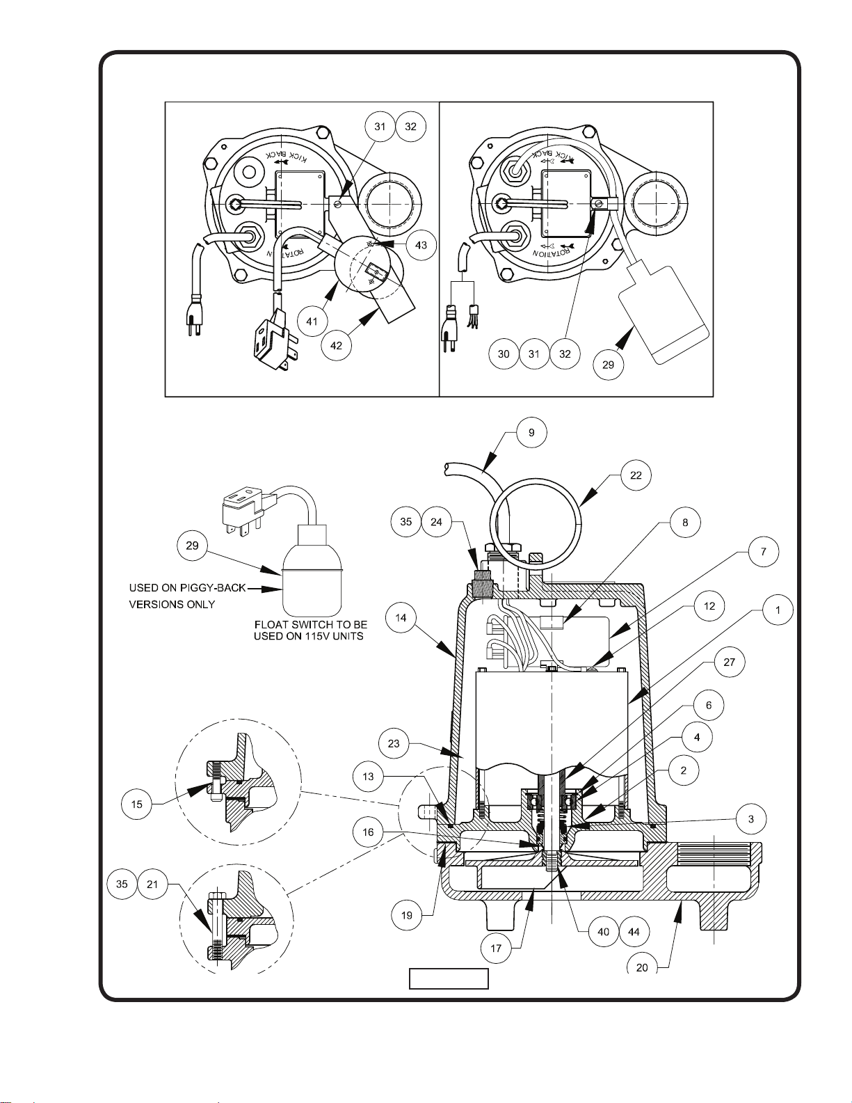
SERIES: BP314 & BP324
FIGURE 14
17
Page 18

SERIES: BP314 & BP324
FIGURE 15
18
Page 19

SERIES: BP314 & BP324
PARTS KITS
Overhaul Kit............... P/N: 085201 (†) 3,4,6,13,16,19,24
Seal Kit....................... P/N: 085202 (◊) 3,13,16,19
Pressure Gauge Kit....P/N: 085343
PARTS LIST
ITEM QTY PART No. DESCRIPTION
1 1 See TABLE 2 Motor & Sleeve
2 1 093063 Seal Plate, BP Series Cast Iron
093247 Seal Plate, BP-BR Series Bronze
3 1 068988 נ Shaft Seal, (Standard) Carbon/Ceramic/Buna-N
068988SB Tungsten/Tungsten/Buna-N
068988SD Silicon/Silicon/Buna-N
4 1 017414 † Bearing
6 1 017415 † Retaining Ring
7 1 112985 ‡ Capacitor, BP314 300V 35MFD
070965 Capacitor, BP324 370V 25MFD
8 1 039858 Capacitor Bracket
----STANDARD TEMPERATURE----
9 1 See TABLE 3 Power Cable Assembly
9a 1 051448 * Gland Nut 1-16
9b 2 051449 * Friction Ring
----HIGH TEMPERATURE----
9 1 See TABLE 3 Power Cable Assembly
9a 1 051448 * Gland Nut 1-16
9b 2 051449 * Friction Ring
9c 1 051451 * Grommet (High Temp.)
10 1 099290 Jumper Wire Assy. “AU” Series
12 1 016660 Self Tapping Screw 8-32 x 3/8 lg Stainless
13 1 019289 נ O-Ring
14 1 See TABLE 2 Motor Housing
15 2 11-32-1 Socket Hd. Cap Screw 1/4-20 x 1.25” Stainless
16 1 068053 נ Exclusion Seal
17 1 096725 Impeller, BP Series 5.63” Dia., Polypropylene
096721 Impeller, BP-BR & Hi-Temp 5.63” Dia., Bronze
18 1 099295 Ground Wire Assy
19 1 068984 נ Gasket
20 1 096724 Volute, BP Cast Iron
1 096724B Volute, BP-BR Bronze
21 4 1-140-1 Cap Screw 5/16-18 x 2.00” Stainless
22 1 027271 Handle
23 58 oz 029034 Oil
24 1 015000 † Pipe Plug
25 A/R ----- Loctite #RC609
26 A/R ----- Loctite #242
27 1 ----- Bearing Sleeve PART OF MOTOR ASSEMBLY
(*) Included with item 9
(‡) Units with a Build Code date before 1
1/01 may use capacitor Part Number 070964 or 035864
19
Page 20

SERIES: BP314 & BP324
29 1 Float Switch w/Plug, Mechanical, Series: A & ABR
101758 15FT
101758XA 20FT
101758XC 30FT
101758XF 50FT
29 1 Float Switch High Temp w/Plug, Series: HTA & HTABR
090269 15FT
090269XB 25FT
090269XC 30FT
090269XF 50FT
29 1 099262 Float Switch, Mechanical Series: AU,& AUBR
29 1 090622 Float Switch High Temp, Mech. Series: HTAU & HTAUBR
ITEMS 29A thru 35 ARE FOR MODELS: AU, AUBR, USED WITH 099262 FLOAT.
29a 1 051448 Gland Nut 1-16
29b 1 051449 Friction Ring
30 1 090516 Cord Clip
31 1 20-12-1 Lockwasher #10 Stainless
32 1 2-88-1 Rd Hd Screw 10-32 x 3/8 Lg. Stainless
35 A/R ----- Permatex Sealant #2C
ITEMS 29A thru 35 ARE FOR MODELS: HTAU, HTAUBR, USED WITH 090622 FLOAT.
29a 1 051762 Gland Nut 1-16 Stainless
29b 2 089121 Friction Ring
29c 1 090103 Grommet
30 1 090516 Cord Clip
31 1 20-12-1 Lockwasher #10 Stainless
32 1 2-88-1 Rd Hd Screw 10-32 x 3/8 Lg. Stainless
35 A/R ----- Permatex Sealant #2C
40 A/R ----- Loctite, #242
41 1 100829 Vertical Float Switch Series: VF & VFBR
42 1 100547 Mounting Bracket
43 2 021337 Pan Hd, Self-Taping Screw 10-16, Stainless
44 1 098679 Shim, .030”
45 2 074449 Screw-on Connector Hi-Temp Only
3 074449 Screw-on Connector (HTAU) Hi-Temp Only
46 2 022229 Shrink Tube Hi-Temp Only
3 022229 Shrink Tube (HTAU) Hi-Temp Only
20
Page 21
SERIES: BP314 & BP324
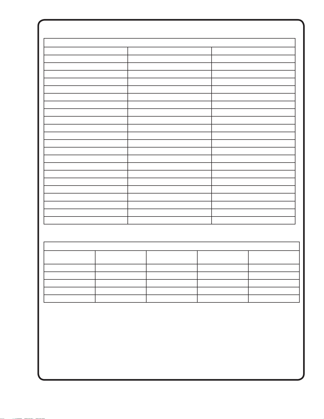
TABLE 2 - MOTOR and HOUSING
PUMP MODEL MOTOR HOUSING (Item #14) MOTOR SLEEVE (Item #1)
BP314 093065 102260
BP314A 093065 102260
BP314AU 093066 102260
BP314VF 093065 102260
BP314BR 093211 102260
BP314ABR 093211 102260
BP314AUBR 093212 102260
BP314VFBR 093211 102260
BP324 093065 098835
BP324AU 093066 098835
BP324BR 093211 098835
BP324AUBR 093212 098835
BP314HT 093065 102260
BP314HTA 093065 102260
BP314HTAU 093066 102260
BP314HTBR 093211 102260
BP314HTABR 093211 102260
BP314HTAUBR 093212 102260
BP324HT 093065 098835
BP324HTAU 093066 098835
BP324HTBR 093211 098835
BP324HTAUBR 093066 098835
TABLE 3 - POWER CORDS SETS
MODELS/
LENGTH
15 FT (5m) STD 099260 099261 100502 100525
20 Ft. (6m) 099260XA 099261XA - -
25 Ft. (7.5m) - - 100502XB 100525XB
30 Ft. (9m) 099260XC 099261XC - -
50 Ft. (15m) 099260XF 099261XF 100502XF 100525XF
ITEM #9
BP314 Series
ITEM #9
BP324 Series
ITEM #9
BP314HT Series
ITEM #9
BP324HT Series
21
Page 22
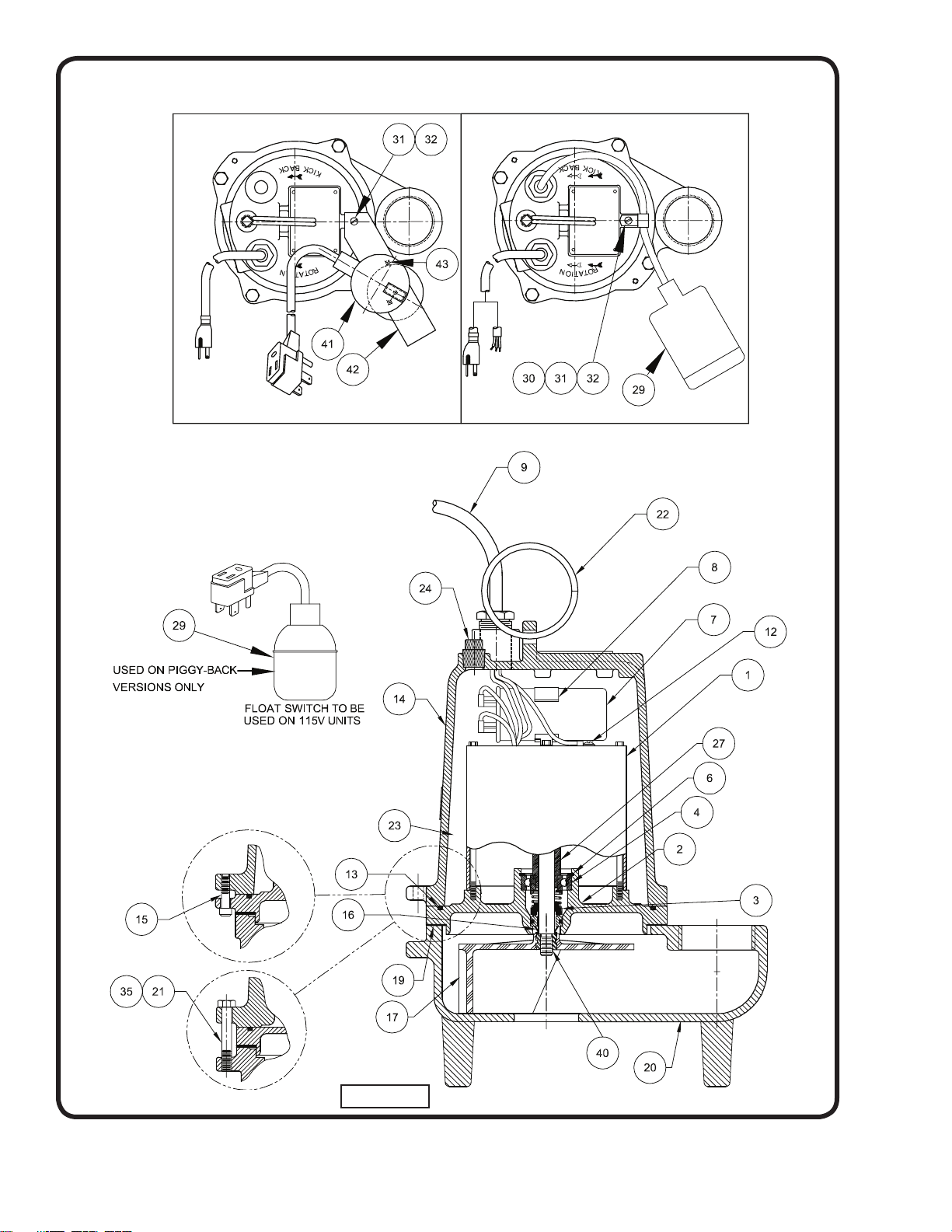
SERIES: SE
FIGURE 16
22
Page 23
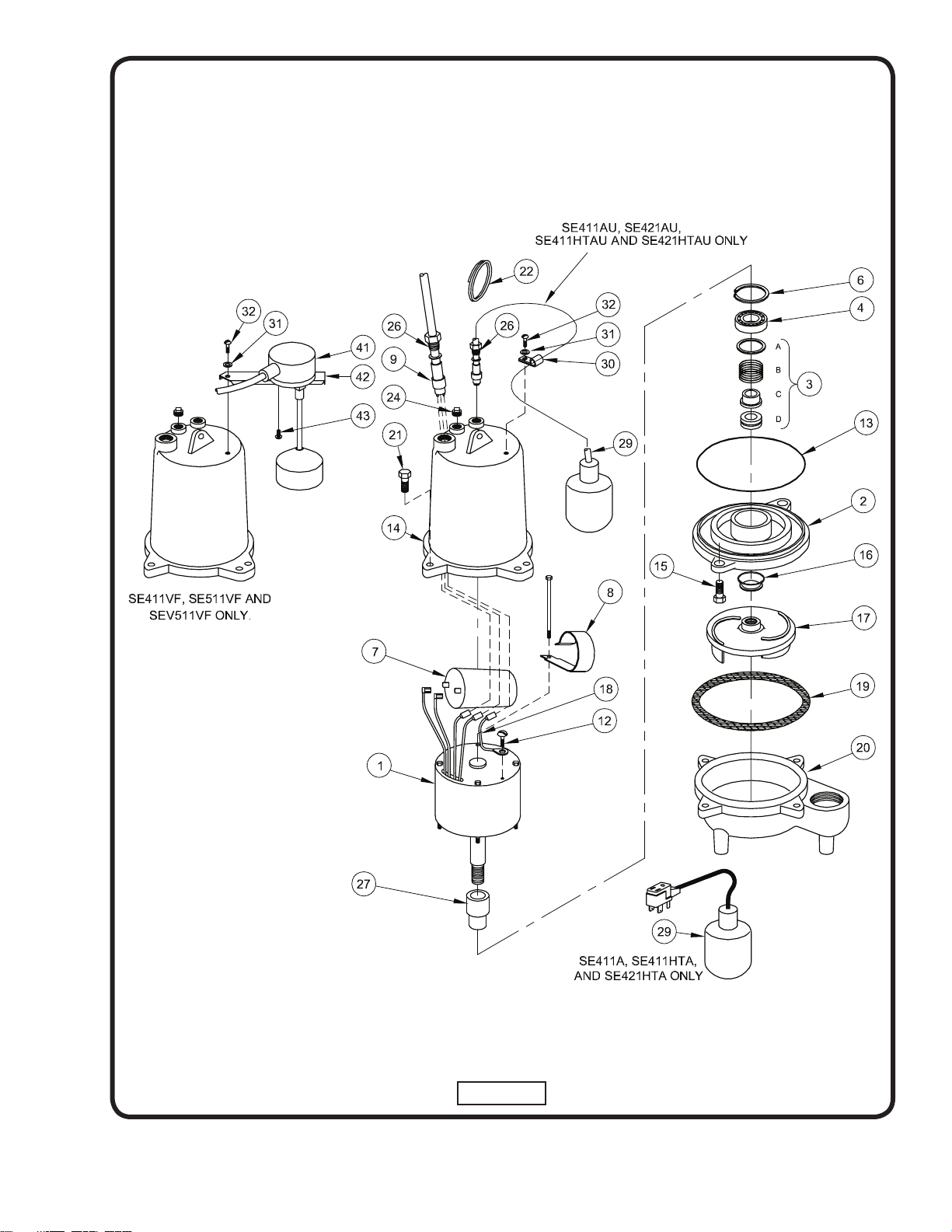
SERIES: SE
FIGURE 17
23
Page 24
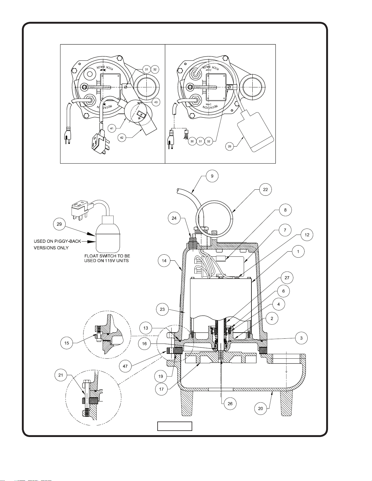
SERIES: SEV
FIGURE 18
24
Page 25
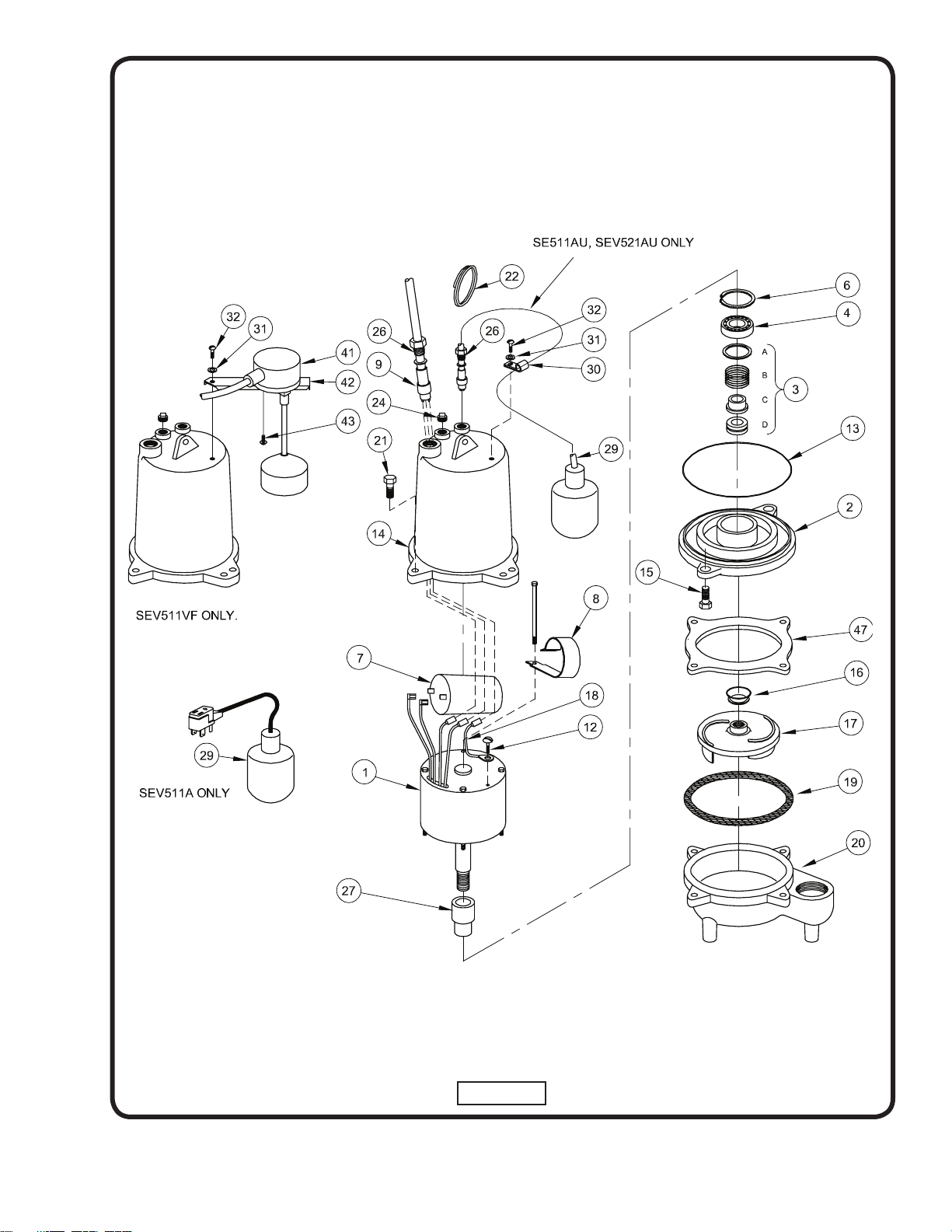
SERIES: SEV
FIGURE 19
25
Page 26

SERIES: SE & SEV
P
ARTS KITS
Overhaul Kit..................... P/N: 085201 (†) 3,4,6,13,16,19,24
Seal Kit............................. P/N: 085202 (◊) 3,13,16,19
PRESSURE GAUGE KIT.. P/N: 085343
PARTS LIST
ITEM QTY PART No. DESCRIPTION
1 1 See TABLE 2 Motor & Sleeve
2 1 093063 Seal Plate Cast Iron
3 1 068988 נ Shaft Seal, (Standard) Carbon/Ceramic/Buna-N
068988SB Tungsten/Tungsten/Buna-N
068988SD Silicon/Silicon/Buna-N
4 1 017414 † Bearing
6 1 017415 † Retaining Ring
7 1 112985 ‡ Capacitor, SE411 300V 35MFD
070965 Capacitor, SE421 & Hi-Temp 370V 25MFD
070965 Capacitor, SE511-521, SEV511-521, 370V 25MFD
8 1 039858 Capacitor Bracket
----STANDARD TEMPERATURE----
9 1 See TABLE 3 Power Cable Assembly
9a 1 051448 * Gland Nut 1-16
9b 2 051449 * Friction Ring
----HIGH TEMPERATURE----
9 1 See TABLE 3 Power Cable Assembly
9a 1 051448 * Gland Nut 1-16
9b 2 051449 * Friction Ring
9c 1 051451 * Grommet
10 1 099290 Jumper Wire Assy. “AU” Series
12 1 016660 Self Tapping Screw 8-32 x 3/8 lg Stainless
13 1 019289 נ O-Ring
14 1 See TABLE 2 Motor Housing
15 2 084948 Socket Hd. Cap Screw 1/4-20 x 1.25” Stainless
16 1 068053 נ Exclusion Seal
17 1 112561 Impeller, SE411-421 5.44” Dia., Cast Iron**
089369TG Impeller, SE411-421 Hi-Temp 4.50” Dia., Cast Iron
096722 Impeller, SE511-521 5.63” Dia., Cast Iron
096723CI Impeller, SEV511-521 5.63” Dia., Cast Iron
18 1 099295 Ground Wire Assy
19 1 068984 נ Gasket
20 1 089120 Volute Cast Iron
21 4 1-172-1 Hex Hd Cap Screw , SEV511-521 5/16-18 x 3.25” Stainless
4 1-299-1 Hex Hd Cap Screw , SE411-421 5/16-18 x 2.75” Stainless
22 1 027271 Handle
23 58 oz. 029034 Oil
24 1 015000 † Pipe Plug
25 A/R ----- Loctite #RC609
26 A/R ----- Loctite #242
27 1 ----- Bearing Sleeve PART OF MOTOR ASSEMBLY
(*) Included with item 9
(**) Cast Iron Impeller replaces Zytel Impeller 089116, 5/02.
(‡) Units with a Build Code date before 11/01 may use capacitor Part Number 070964 or 035864
26
Page 27

SERIES: SE & SEV
29 1 Float Switch w/Plug, Mechanical Series: A
101758 15FT
101758XA 20FT
101758XC 30FT
101758XF 50FT
29 1 Float Switch High Temp w/Plug Series: HTA
090269 15FT
090269XB 25FT
090269XC 30FT
090269XF 50FT
29 1 099262 Float Switch, Mechanical Series: AU
29 1 090622 Float Switch High Temp, Mech. Series: HTAU
ITEMS 29A thru 35 ARE FOR MODELS: AU, USED WITH 099262 FLOAT.
29a 1 051448 Gland Nut 1-16
29b 1 051449 Friction Ring
30 1 090516 Cord Clip
31 1 20-12-1 Lockwasher #10 Stainless
32 1 2-88-1 Rd Hd Screw 10-32 x 3/8 Lg. Stainless
35 A/R ----- Permatex Sealant #2C
ITEMS 29A thru 35 ARE FOR MODELS: HTAU, USED WITH 090622 FLOAT.
29a 1 051762 Gland Nut 1-16 Stainless
29b 2 089121 Friction Ring
29c 1 090103 Grommet
30 1 090516 Cord Clip
31 1 20-12-1 Lockwasher #10 Stainless
32 1 2-88-1 Rd Hd Screw 10-32 x 3/8 Lg. Stainless
35 A/R ----- Permatex Sealant #2C
40 A/R ----- Loctite, #242
41 1 100829 Vertical Float Switch Series: VF
42 1 100547 Mounting Bracket
43 2 021337 Pan Hd, Self-Taping Screw 10-16, Stainless
45 2 074449 Screw-on Connector Hi-Temp Only
3 074449 Screw-on Connector (HTAU) Hi-Temp Only
46 2 022229 Shrink Tube Hi-Temp Only
3 022229 Shrink Tube (HTAU) Hi-Temp Only
47 1 096726 Adapter Plate SEV, Only
27
Page 28
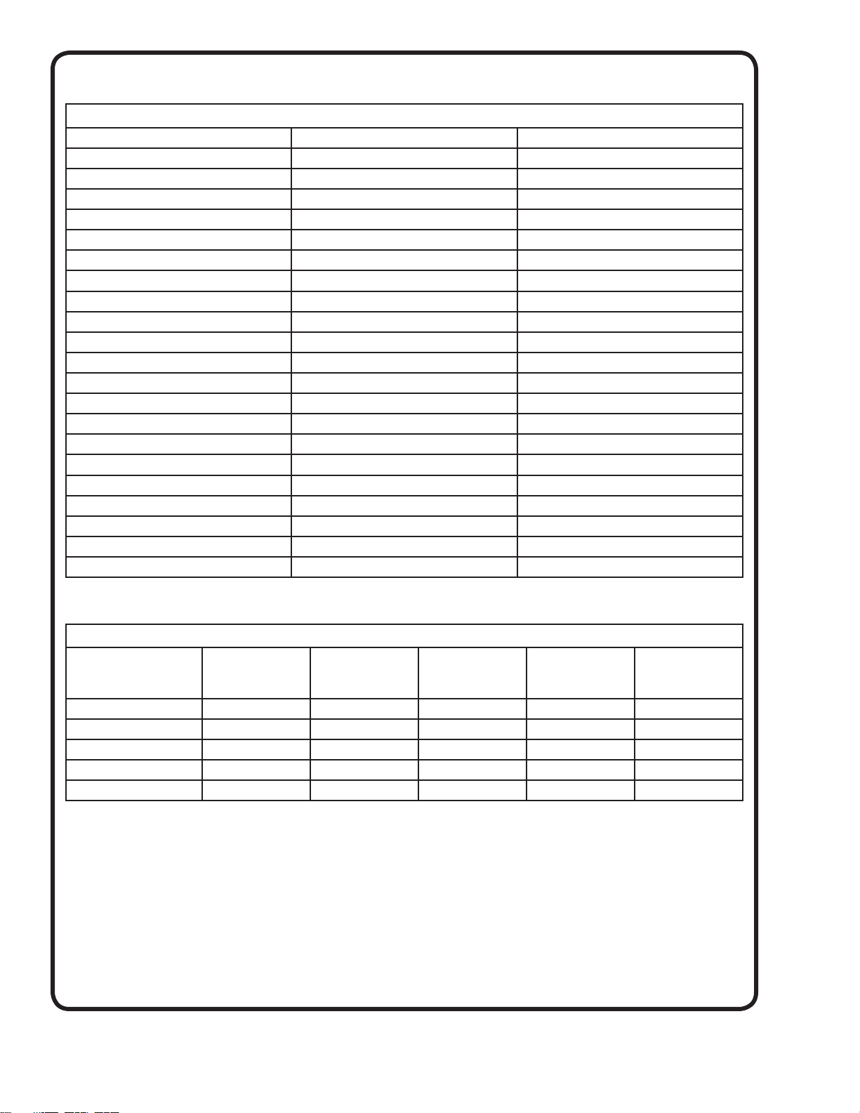
SERIES: SE & SEV
TABLE 2 - MOTOR and HOUSING
PUMP MODEL MOTOR HOUSING (Item #14) MOTOR SLEEVE (Item #1)
SE411 093065 102260
SE411A 093065 102260
SE411VF 093065 102260
SE421 093065 098835
SE411HT 093065 098838
SE411HTA 093065 098838
SE411HTAU 093066 098838
SE421HT 093065 098835
SE421HTAU 093066 098835
SE511 093065 098838
SE511A 093065 098838
SE511AU 093066 098838
SE511VF 093065 098838
SE521 093065 098835
SE521AU 093066 098835
SEV511 093065 098838
SEV511A 093065 098838
SEV511AU 093066 098838
SEV511VF 093065 098838
SEV521 093065 098835
SEV521AU 093066 098835
TABLE 3 - POWER CORDS SETS
MODELS/
LENGTH
15 FT (5m) STD 138154 099260 099261 100502 100525
20 Ft. (6m) 138154XA 099260XA 099261XA - -
25 Ft. (7.5m) - - - 100502XB 100525XB
30 Ft. (9m) 138154XC 099260XC 099261XC - -
50 Ft. (15m) 138154XF 099260XF 099261XF 100502XF 100525XF
ITEM #9
SE411 Series
ITEM #9
SE511, SEV511
ITEM #9
SE421 Series &
SE521, SEV521
ITEM #9
SE411HT Series
ITEM #9
SE421HT Series
28
Page 29
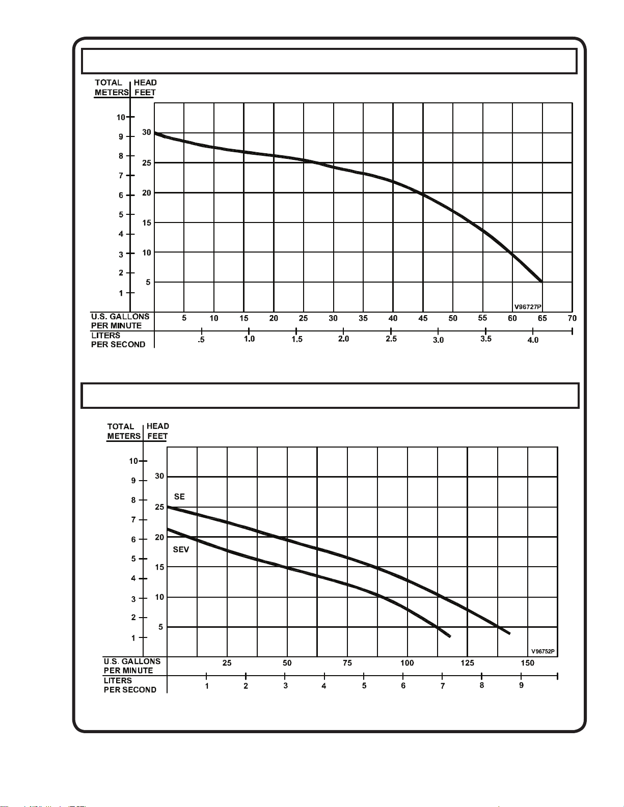
SERIES: BP314, BP324, BP314HT & BP324HT
SERIES: SE511, SE521, SEV511 & SEV521
Testing is performed with water specifi c gravity of 1.0 @ 68˚F (20˚C), other fl uids may vary performance
29
Page 30
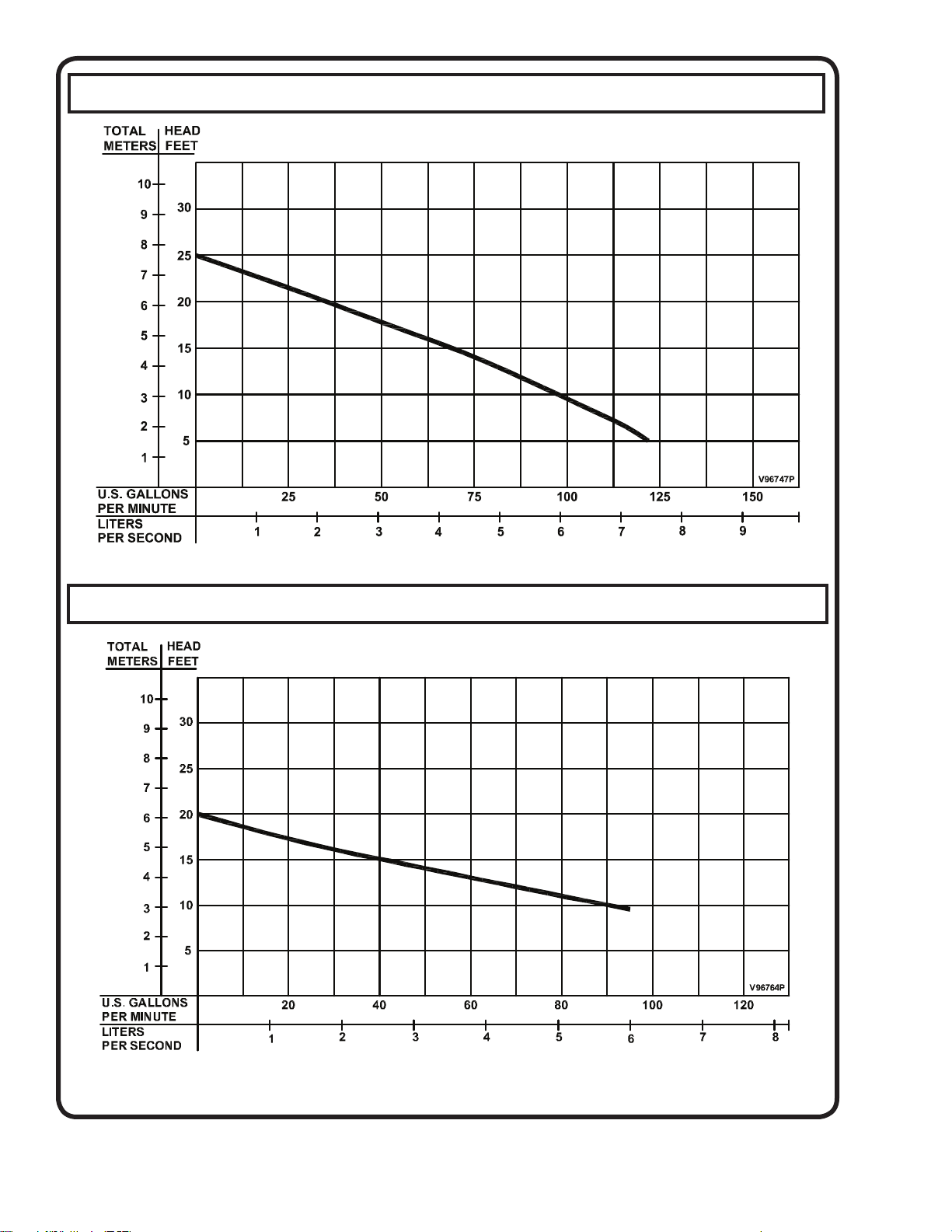
SERIES: SE411 & SE421
SERIES: SE411HT & SE421HT
Testing is performed with water specifi c gravity of 1.0 @ 68˚F (20˚C), other fl uids may vary performance
30
Page 31
A Crane Co. Company
Limited 24 Month Warranty
Crane Pumps & Systems warrants that products of our manufacture will be free of defects in material and workmanship
under normal use and service for twenty-four (24) months after manufacture date, when installed and maintained
in accordance with our instructions.This warranty gives you speci• c legal rights, and there may also be other rights
which vary from state to state. In the event the product is covered by the Federal Consumer Product Warranties Law
(1) the duration of any implied warranties associated with the product by virtue of said law is limited to the same
duration as stated herein, (2) this warranty is a LIMITED WARRANTY, and (3) no claims of any nature whatsoever
shall be made against us, until the ultimate consumer, his successor, or assigns, noti• es us in writing of the defect,
and delivers the product and/or defective part(s) freight prepaid to our factory or nearest authorized service station.
Some states do not allow limitations on how long an implied warranty lasts, so the above limitation may not apply.
THE SOLE AND EXCLUSIVE REMEDY FOR BREACH OF ANY AND ALL WARRANTIES WITH RESPECT TO ANY
PRODUCT SHALL BE TO REPLACE OR REPAIR AT OUR ELECTION, F.O.B. POINT OF MANUFACTURE OR
AUTHORIZED REPAIR STATION, SUCH PRODUCTS AND/OR PARTS AS PROVEN DEFECTIVE. THERE SHALL BE
NO FURTHER LIABILITY, WHETHER BASED ON WARRANTY, NEGLIGENCE OR OTHERWISE. Unless expressly
stated otherwise, guarantees in the nature of performance speci• cations furnished in addition to the foregoing material
and workmanship warranties on a product manufactured by us, if any, are subject to laboratory tests corrected for
• eld performance. Any additional guarantees, in the nature of performance speci• cations must be in writing and such
writing must be signed by our authorized representative. Due to inaccuracies in • eld testing if a con! ict arises between
the results of • eld testing conducted by or for user, and laboratory tests corrected for • eld performance, the latter
shall control. RECOMMENDATIONS FOR SPECIAL APPLICATIONS OR THOSE RESULTING FROM SYSTEMS
ANALYSES AND EVALUATIONS WE CONDUCT WILL BE BASED ON OUR BEST AVAILABLE EXPERIENCE AND
PUBLISHED INDUSTRY INFORMATION. SUCH RECOMMENDATIONS DO NOT CONSTITUTE A WARRANTY OF
SATISFACTORY PERFORMANCE AND NO SUCH WARRANTY IS GIVEN.
This warranty shall not apply when damage is caused by (a) improper installation, (b) improper voltage (c) lightning
(d) excessive sand or other abrasive material (e) scale or corrosion build-up due to excessive chemical content. Any
modi• cation of the original equipment will also void the warranty. We will not be responsible for loss, damage or labor
cost due to interruption of service caused by defective parts. Neither will we accept charges incurred by others without
our prior written approval.
This warranty is void if our inspection reveals the product was used in a manner inconsistent with normal industry practice
and\or our speci• c recommendations. The purchaser is responsible for communication of all necessary information
regarding the application and use of the product. UNDER NO CIRCUMSTANCES WILL WE BE RESPONSIBLE FOR
ANY OTHER DIRECT OR CONSEQUENTIAL DAMAGES, INCLUDING BUT NOT LIMITED TO TRAVEL EXPENSES,
RENTED EQUIPMENT, OUTSIDE CONTRACTOR FEES, UNAUTHORIZED REPAIR SHOP EXPENSES, LOST
PROFITS, LOST INCOME, LABOR CHARGES, DELAYS IN PRODUCTION, IDLE PRODUCTION, WHICH DAMAGES
ARE CAUSED BY ANY DEFECTS IN MATERIAL AND\OR WORKMANSHIP AND\OR DAMAGE OR DELAYS IN
SHIPMENT. THIS WARRANTY IS EXPRESSLY IN LIEU OF ANY OTHER EXPRESS OR IMPLIED WARRANTY,
INCLUDING ANY WARRANTY OF MERCHANTABILITY OR FITNESS FOR A PARTICULAR PURPOSE.
No rights extended under this warranty shall be assigned to any other person, whether by operation of law or otherwise,
without our prior written approval.
420 Third Street 83 West Drive
Piqua, Ohio 45356 Brampton, Ont. Canada L6T 2J6
(937) 778-8947 (905) 457-6223
Fax (937) 773-7157 Fax (905) 457-2650
www.cranepumps.com
Page 32
RETURNED GOODS
RETURN OF MERCHANDISE REQUIRES A “RETURNED GOODS AUTHORIZATION”.
CONTACT YOUR LOCAL CRANE PUMPS & SYSTEMS, INC. DISTRIBUTOR.
Products Returned Must Be Cleaned, Sanitized,
Or Decontaminated As Necessary Prior To Shipment,
To Insure That Employees Will Not Be Exposed To Health
Hazards In Handling Said Material. All Applicable Laws
And Regulations Shall Apply.
IMPORTANT!
WARRANTY REGISTRATION
Your product is covered by the enclosed Warranty.
To complete the Warranty Registration Form go to:
http://www.cranepumps.com/ProductRegistration/
If you have a claim under the provision of the warranty, contact your local
Crane Pumps & Systems, Inc. Distributor.
 Loading...