


2ADE11
Barnes 2ADE11, 2ADE13, 2CDE11, 2CDE13, 3ADE151 Installation And Operation Manual
...
BARNES
®
BARNES
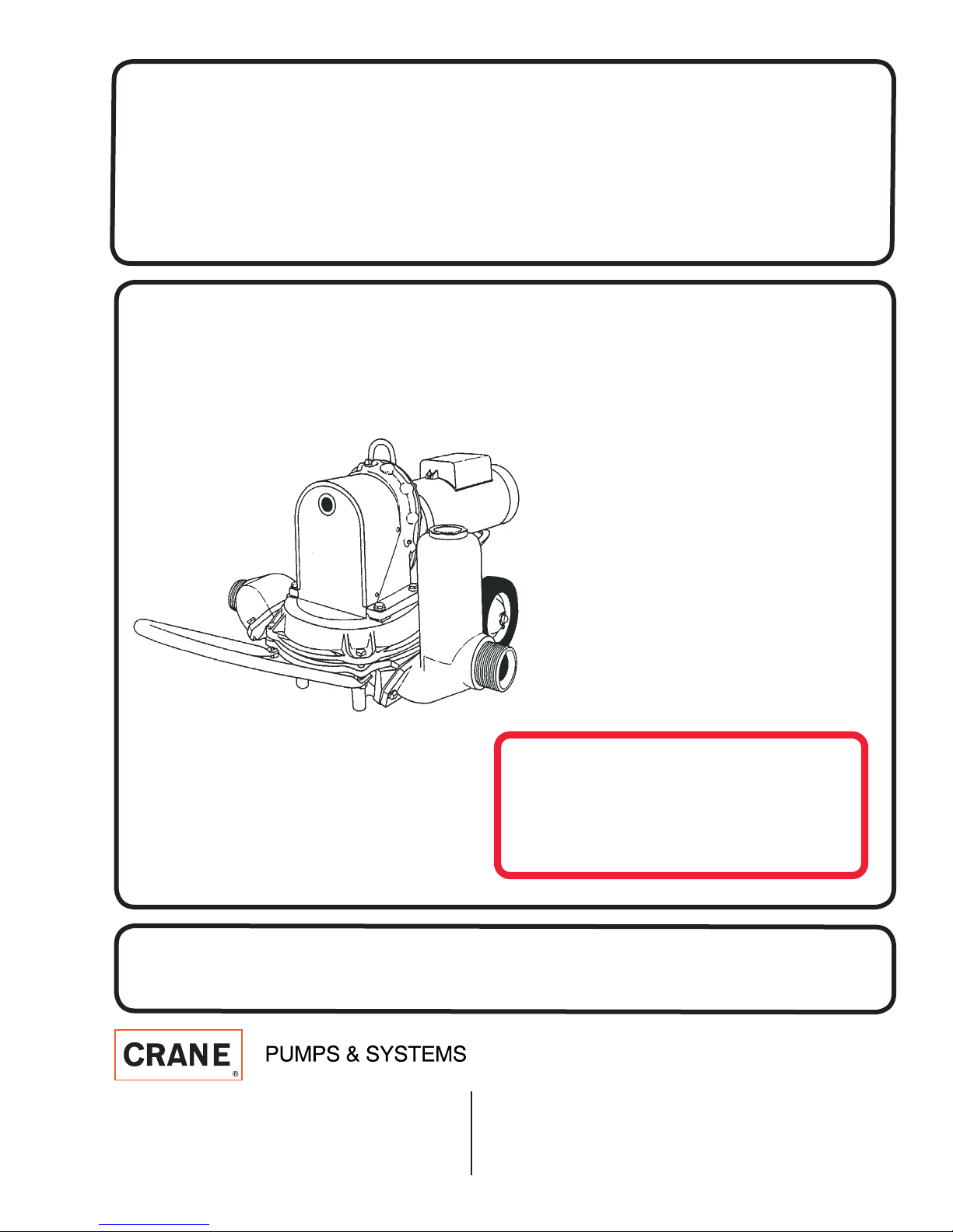
INSTALLATION and OPERATION MANUAL
Diaphragm Pumps
Models:
2ADE11, 2CDE11
2ADE13, 2CDE13
3ADE151, 3CDE151
3ADE153, 3CDE153
DISCONTINUED
Parts NOT available
IMPORTANT! Read all instructions in this manual before operating pump.
As a result of Crane Pumps & Systems, Inc., constant product improvement program,
product changes may occur. As such Crane Pumps & Systems reserves the right to
change product without prior written notifi cation.
A Crane Co. Company
420 Third Street 83 West Drive, Bramton
Piqua, Ohio 45356 Ontario, Canada L6T 2J6
Phone: (937) 778-8947 Phone: (905) 457-6223
Fax: (937) 773-7157 Fax: (905) 457-2650
www.cranepumps.com
Form No. 082924-Rev. F

TABLE OF CONTENTS
SAFETY FIRST ............................................................................................... 3
A. PUMP SPECIFICATIONS ............................................................................... 4 - 5
B. GENERAL INFORMATION ............................................................................. 6
C. PREPARE PUMP FOR OPERATION ............................................................. 6
D. MAINTENANCE INSTRUCTIONS .................................................................. 7
E. TROUBLE SHOOTING ................................................................................... 7
F. REPLACEMENT PARTS ................................................................................. 7
EXPLODED VIEW .......................................................................................... 8
PARTS LIST - SERIES 2CDE & 3CDE ........................................................... 9 - 10
PARTS LIST - SERIES 2ADE & 3ADE ........................................................... 11 - 12
RETURNED GOODS POLICY ........................................................................ 13
WARRANTY .................................................................................................. 14
START-UP REPORT ....................................................................................... 17 - 18
WARRANTY REGISTRATION
Other brand and product names are trademarks or registered trademarks of their respective holders.
® Barnes is a registered trademark of Crane Pumps & Systems, Inc
1987, 1997, 1998, 2002, 3/06, 9/06 Alteration Rights Reserved
2
SAFETY FIRST!
Please Read This Before Installing Or Operating Pump.
This information is provided for SAFETY and to PREVENT
EQUIPMENT PROBLEMS. To help recognize this information,
observe the following symbols:
IMPORTANT! Warns about hazards that can result
in personal injury or Indicates factors concerned with
assembly, installation, operation, or maintenance which
could result in damage to the machine or equipment if
ignored.
Always wear eye protection when working on pumps.
Make sure lifting handles are securely fastened each
time before lifting. DO NOT operate pump without
safety devices in place. Always replace safety devices
that have been removed during service or repair.
Secure the pump in its operating position so it can not
tip over, fall or slide.
CAUTION ! Warns about hazards that can or will cause minor
personal injury or property damage if ignored. Used with symbols
below.
WARNING ! Warns about hazards that can or will cause serious
personal injury, death, or major property damage if ignored. Used
with symbols below.
Hazardous fl uids can
cause fi re or explosions, burnes or death
could result.
Biohazard can cause
serious personal injury.
Rotating machinery
Amputation or severe
laceration can result.
Toxic Fumes Breathing can cause
nausea, fainting or death
Extremely hot - Severe
burnes can occur on contact.
Hazardous fl uids can Hazardous pressure, eruptions or explosions could cause personal
injury or property damage.
Hazardous voltage can
shock, burn or cause death.
Eye protectiong required
Only qualifi ed personnel should install, operate and repair pump.
WARNING! Operation against a closed
discharge valve will cause premature bearing
and seal failure on any pump, and on end
suction and self priming pump the heat build
may cause the generation of steam with resulting dangerous
pressures. It is recommended that a high case temperature
switch or pressure relief valve be installed on the pump body.
CAUTION! Pumps build up heat and pressure
during operation-allow time for pumps to cool
before handling or servicing.
WARNING! - DO NOT pump hazardous materials
(fl ammable, caustic, etc.) unless the pump is specifi cally
designed and designated to handle them.
CAUTION! - Do not block or restrict discharge hose, as
discharge hose may whip under pressure.
WARNING! - DO NOT wear loose clothing that may
become entangled in the impeller or other moving parts.
Always wear appropriate safety gear, such as safety
glasses, when working on the pump or piping.
WARNING! - Keep clear of suction and discharge
openings. DO NOT insert fi ngers in pump with power
connected.
DO NOT exceed manufacturers recommendation for
maximum performance, as this could cause the motor
to overheat.
When towing pump behind a vehicle, make sure hitch is
properly attached, always attach safety chains.
WARNING! If Engine driven, never operate in an
enclosed building or area where exhaust gases can
accumulate. Never operate near a building where
exhaust gases can seep inside. Never operate in a
pit or sump without making provisions for adequate
ventilation.
WARNING! Do not breathe exhaust fumes when
working in the area of the engine. (Exhaust gases are
odorless and deadly poison.)
WARNING! Allow exhaust system to cool before
touching.
Never add fuel to the tank while the engine is running.
Stop engine and allow to cool.
Do not smoke while refueling the engine
Do not refuel near open fl ame
Carefully read instruction manuals supplied by engine
manufacture before attempting to assemble, operate
or service the engine or any part. The “WARNING”
statements indicate potentially hazardous conditions for
operator or equipment.
WARNING! Products Returned Must Be Cleaned,
Sanitized, Or Decontaminated As Necessary Prior
To Shipment, To Insure That Employees Will Not Be
Exposed To Health Hazards In Handling Said Material.
All Applicable Laws And Regulations Shall Apply.
Bronze/brass and bronze/brass fi tted pumps may
contain lead levels higher than considered safe for
potable water systems. Lead is known to cause cancer
and birth defects or other reproductive harm. Various
government agencies have determined that leaded
copper alloys should not be used in potable water
applications. For non-leaded copper alloy materials of
construction, please contact factory.
IMPORTANT! - Crane Pumps & Systems, Inc. is not
responsible for losses, injury, or death resulting from a
failure to observe these safety precautions, misuse or
abuse of pumps or equipment.
3
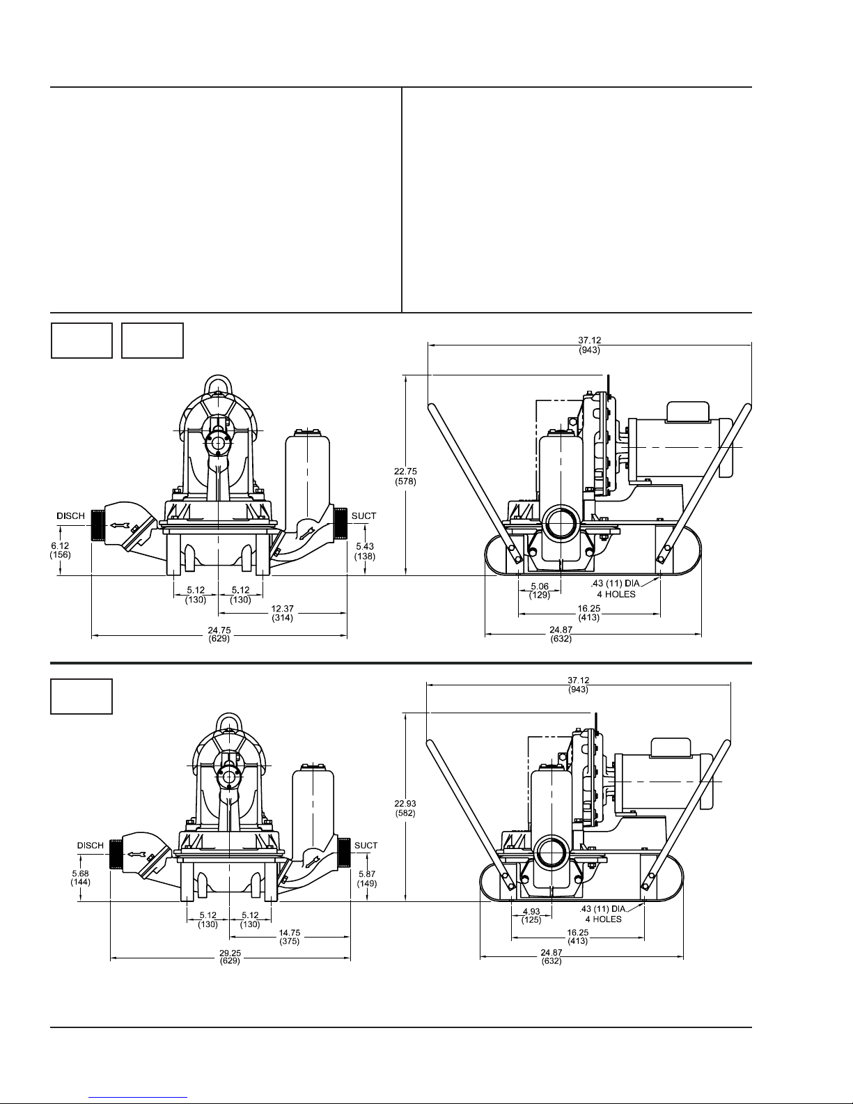
SECTION: A - PUMP SPECIFICATIONS: Skid Mounted
SUCTION/DISCHARGE:
2ADE-2CDE ....... 2” x 2" NPT
3ADE-3CDE ........ 3” x 3” NPT
LIQUID TEMPERATURE ... 160°F (71°C) Continuous
SUCT/DISCH CHAMBER
ADE ..................... Aluminum, Class 319
CDE ..................... Cast Iron ASTM A-48, Class 30
WATER BOX
ADE .................... Aluminum, Class 319
CDE ..................... Cast Iron ASTM A-48, Class 30
DIAPHRAGM BOTTOM
ADE ..................... Aluminum, Class 319
CDE ..................... Cast Iron ASTM A-48, Class 30
DIAPHRAGM ..................... Thermal Plastic Elastomer (TPE)
inches
(mm)
2”
BEARING ........................... Ball
FLAP VALVE ...................... Natural Rubber
PAINT ................................. Air Dry Enamel
TRANSMISSION ................ Enclosed, Oil Bath, Double
Reduction
GEAR RATIO ................. 43:1
OUTPUT STROKES .......... 41 Per Minute
MOTOR: Design ................. TEFC NEMA B Torque curve,
C-Face, Squirrel cage induction
Insulation ............. Class B
SINGLE PHASE ................. Dual Voltage 115/230
THREE PHASE ................. Dual Voltage 230/460
OPTIONAL EQUIPMENT ... Across the Line Manual Starter
3”
IMPORTANT !
1.) DO NOT USE FOR PUMPING FLUIDS WITH A FLASH POINT OF LESS THAN 100°F.
2.) MAKE CERTAIN THAT PUMP AND/OR MOTOR ASSEMBLY AND CONTROLS HAVE THE APPROPRIATE RATINGS FOR THE GIVEN APPLICATION
AREA CLASSIFICATION. (ie DIVISION I, AGENCY LISTING ETC.)
4
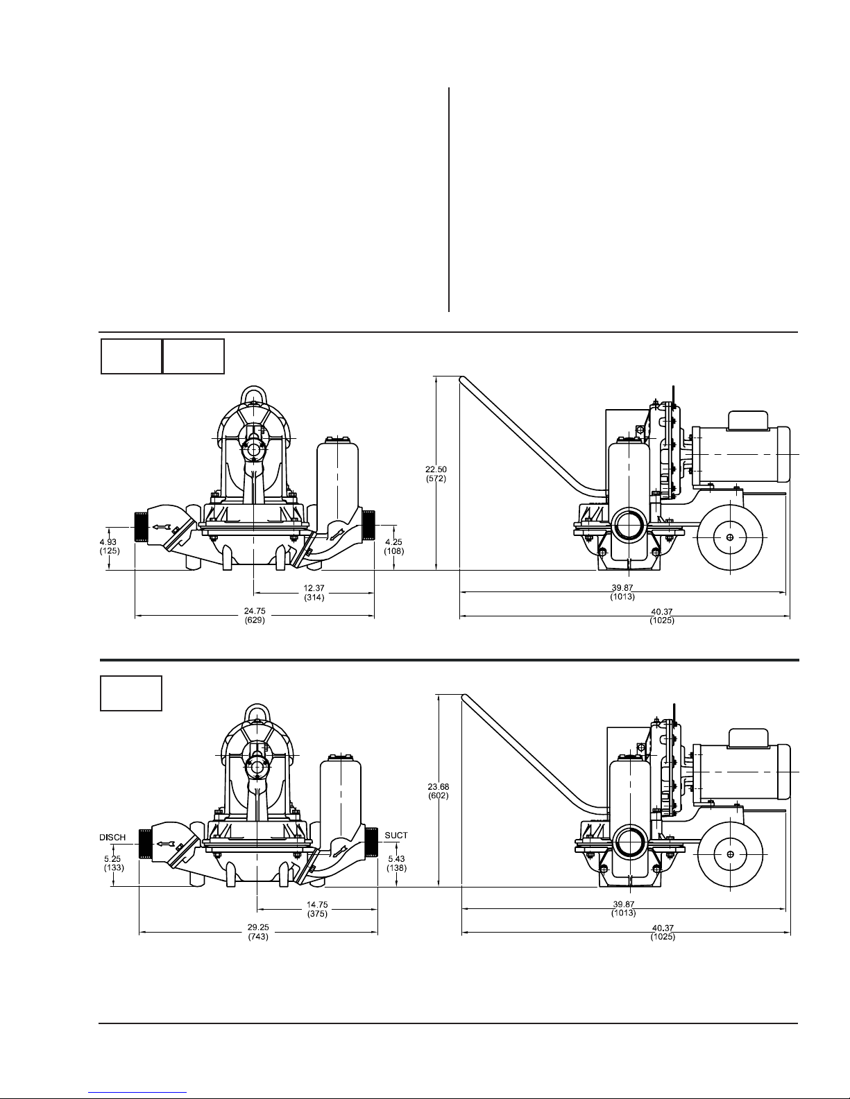
SECTION: A - PUMP SPECIFICATIONS: Wheel Mounted
SUCTION/DISCHARGE:
2ADE-2CDE ....... 2” x 2" NPT
3ADE-3CDE ........ 3” x 3” NPT
LIQUID TEMPERATURE ... 160°F (71°C) Continuous
SUCT/DISCH CHAMBER
ADE ..................... Aluminum, Class 319
CDE ..................... Cast Iron ASTM A-48, Class 30
WATER BOX
ADE .................... Aluminum, Class 319
CDE ..................... Cast Iron ASTM A-48, Class 30
DIAPHRAGM BOTTOM
ADE ..................... Aluminum, Class 319
CDE ..................... Cast Iron ASTM A-48, Class 30
DIAPHRAGM ..................... Thermal Plastic Elastomer (TPE)
BEARING ........................... Ball
inches
(mm)
2”
FLAP VALVE ...................... Natural Rubber
PAINT ................................. Air Dry Enamel
TRANSMISSION ................ Enclosed, Oil Bath, Double
Reduction
GEAR RATIO ..................... 43:1
OUTPUT STROKES .......... 41 Per Minute
TIRES ................................. 8” x 1.75 (used on ADE & CDE11-1
............................................ ADE & CDE13-1
MOTOR: Design ................. TEFC NEMA B Torque curve,
C-Face, Squirrel cage induction
Insulation ............. Class B
SINGLE PHASE ................. Dual Voltage 115/230
THREE PHASE ................. Dual Voltage 230/460
OPTIONAL EQUIPMENT ... Across the Line Manual Starter
3”
IMPORTANT !
1.) DO NOT USE FOR PUMPING FLUIDS WITH A FLASH POINT OF LESS THAN 100°F.
2.) MAKE CERTAIN THAT PUMP AND/OR MOTOR ASSEMBLY AND CONTROLS HAVE THE APPROPRIATE RATINGS FOR THE GIVEN APPLICATION
AREA CLASSIFICATION. (ie DIVISION I, AGENCY LISTING ETC.)
5

SECTION B: GENERAL INFORMATION
B-1) To the Purchaser:
Congratulations! You are the owner of one of the fi nest pumps
on the market today. Barnes® Pumps are products engineered
and manufactured of high quality components. Over one
hundred years of pump building experience along with a
continuing quality assurance program combine to produce a
pump which will stand up to the toughest applications.
This Barnes Pumps manual will provide helpful information
concerning installation, maintenance, and proper service
guidelines.
B-2) Receiving:
Upon receiving the pump, it should be inspected for damage
or shortages. If damage has occurred, fi le a claim immediately
with the company that delivered the pump. If the manual is
removed from the packaging, do not lose or misplace.
B-3) Storage:
Short Term - Barnes Pumps are manufactured for effi cient
performance following long inoperative periods in storage.
For best results, pumps can be retained in storage, as factory
assembled, in a dry atmosphere with constant temperatures
for up to six (6) months.
Long Term - Any length of time exceeding six (6) months, but
not more than twenty four (24) months. The units should be
stored in a temperature controlled area, a roofed over walled
enclosure that provides protection from the elements (rain,
snow, wind blown dust, etc..), and whose temperature can be
maintained between +40 deg. F and +120 deg. F.
If extended high humidity is expected to be a problem, all
exposed parts should be inspected before storage and all
surfaces that have the paint scratched, damaged, or worn
should be recoated with a water base, air dry enamel paint. All
surfaces should then be sprayed with a rust-inhibiting oil.
Pump should be stored in its original shipping container.
B-4) SERVICE CENTERS:
For the location of the nearest Barnes Service Center, your
Barnes representative or Crane Pumps & Systems, Inc.,
Service Department in Piqua, Ohio, telephone (937) 778-8947
or Crane Pumps & Systems Canada Inc., Bramton, Ontario
(905) 457-6223.
SECTION C: PREPARE PUMP FOR OPERATION :
1. Before making electrical power connections, check for
proper grounding of motor and application. All electrical
contacts and connections must be properly insulated and
enclosed.
2. Prior to connecting to the power line, check nameplate
for proper voltage. The motor should be installed in
compliance with the National Electrical Code or the
Canadian Electrical Code and any other applicable codes.
Voltage at motor NOT to exceed + or - 10% of nameplate
voltage.
3. For best performance locate pump as close to water as
possible. Vertical suction lift should not exceed
25 ft. (7.6M) At high lifts, 15 ft. (4.5M) and up, a foot valve
is recommended, and a size smaller suction hose, will
give better operation and same capacity.
4. Extra heavy faced nipples in suction and discharge
connections protect the threads in these castings.
To connect a hose fi tted with a male nipple, use a
coupling or union. Seal threads with grease or thread
sealer to prevent air leaks. To connect a hose fi tted with
a female coupling, gasket must be in place and in good
condition. Suction hose must be in good condition with
no leaks and lining tight. A loose lining will collapse under
suction and keep liquid from being drawn into pump. A
coarse strainer at end of suction hose is advisable if there
is a possibility of pumping large, hard, unbreakable solids,
such as, rocks, wood, tin cans, etc., that could be caught
between connecting rod and water box, causing pump
damage.
5. To lead water away, connect non-collapsible suction hose
to nipple in discharge connection. Discharge hose should
not be smaller than suction hose and not kinked. It is
helpful to use a short piece of hose at any time, with
open end raised a foot or so above discharge connection.
This retains water to seal the discharge valve and
improves capacity and operation. Discharge head should
never exceed 25 ft. (7.6M).
6. On high lifts, or if pump has been idle and valves are dry,
remove cap on suction chamber and pour water into pump.
This will seal valves and speed up priming. Replace cover
securely to keep air from leaking into suction line.
7. Drain pump in freezing weather by tipping unit toward
discharge side with hoses disconnected.
8. Check oil level in the pump transmission. If it is not up to
the oil level plug in the cover, top off with an
SAE 80 - 90 EP gear lube. Transmission oil capacity is
20 oz. (550 ml).
MODEL NO SIZE
NPT
INCHES
2ADE11 2 1.0 115/230/1 60 1750 K 12.8/6.4 37
2ADE13 2 1.0 230/460/3 60 1750 J 3.8/1.9 22
2CDE11 2 1.0 115/230/1 60 1750 K 12.8/6.4 37
2CDE13 2 1.0 230/460/3 60 1750 J 3.8/1.9 22
3ADE151 3 1.5 115/230/1 60 1750 J 17.2/8.6 52
3ADE153 3 1.5 230/460/3 60 1750 J 4.6/2.3 29
3CDE151 3 1.5 115/230/1 60 1750 J 17.2/8.6 52
3CDE153 3 1.5 230/460/3 60 1750 J 4.6/2.3 29
(*) Electrical data subject to Motor manufacture.
HP VOLT/PH Hz RPM
(Nom)
NEMA
START
CODE *
FULL
LOAD
AMPS *
LOCKED
ROTOR
AMPS *
6
 Loading...