

Page 1
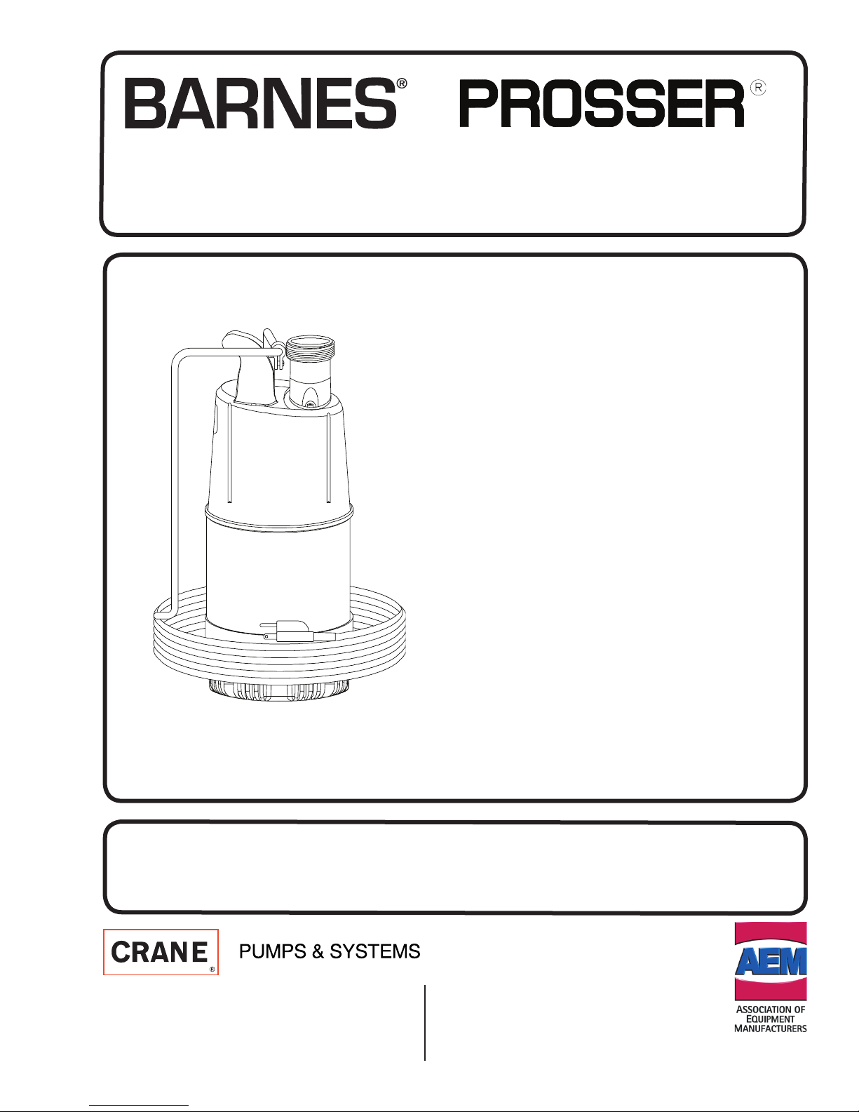
INSTALLATION MANUAL
Portable Submersible Pump
70 Series
0.7 HP, 120 Volt
0.7 HP, 240 Volt
125 Series
1.25 HP, 120 Volt
1.25 HP, 240 Volt
IMPORTANT! Read all instructions in this manual before operating pump.
As a result of Crane Pumps & Systems, Inc., constant product improvement program,
product changes may occur. As such Crane Pumps & Systems reserves the right to
change product without prior written notifi cation.
A Crane Co. Company
420 Third Street 83 West Drive, Bramton
Piqua, Ohio 45356 Ontario, Canada L6T 2J6
Phone: (937) 778-8947 Phone: (905) 457-6223
Fax: (937) 773-7157 Fax: (905) 457-2650
www.cranepumps.com
Form No. 115150-Rev. J
Page 2
SAFETY FIRST!
Please Read This Before Installing Or Operating Pump.
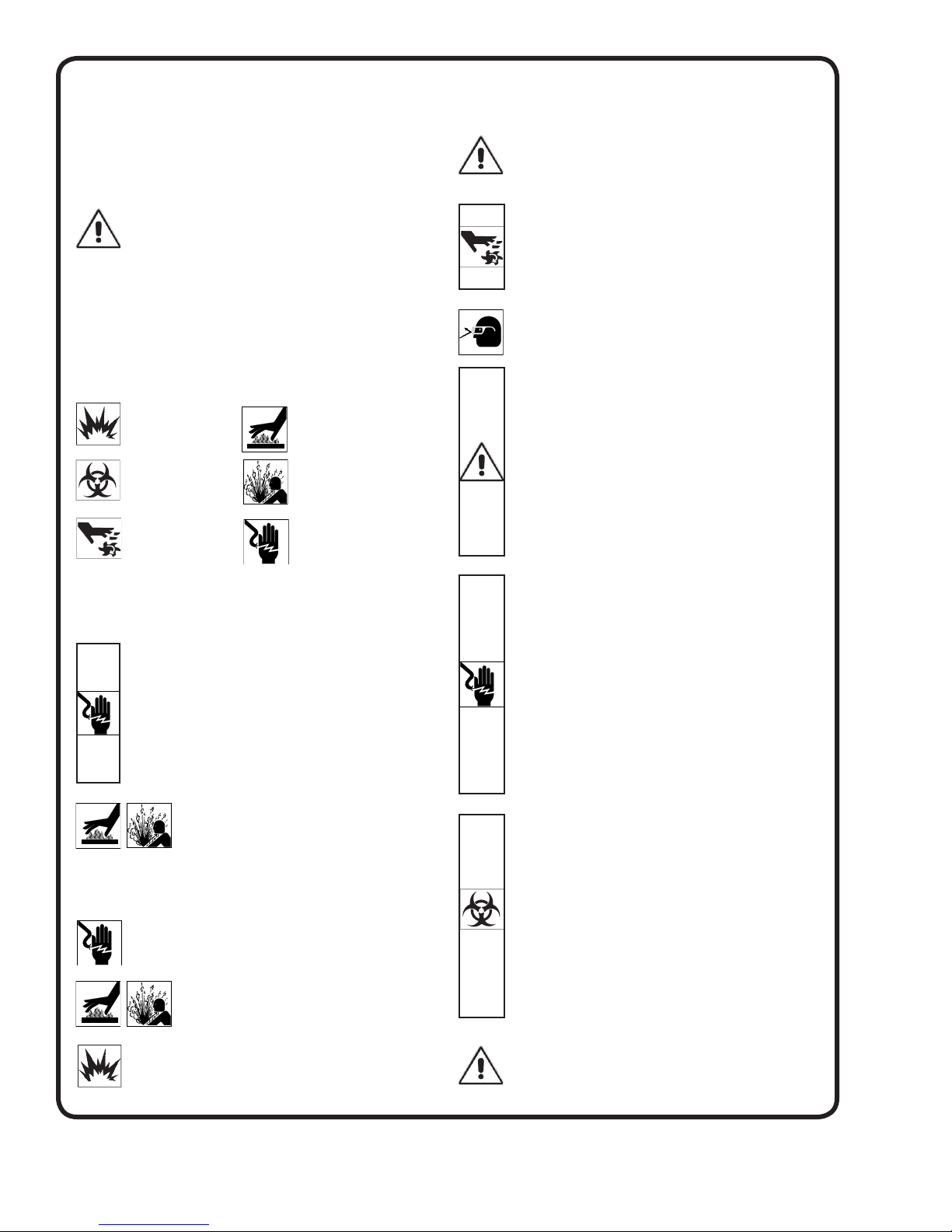
This information is provided for SAFETY and to PREVENT
EQUIPMENT PROBLEMS. To help recognize this information,
observe the following symbols:
IMPORTANT! Warns about hazards that can result
in personal injury orIndicates factors concerned with
assembly, installation, operation, or maintenance which
could result in damage to the machine or equipment if
ignored.
CAUTION! Warns about hazards that can or will cause minor
personal injury or property damage if ignored. Used with symbols
below.
WARNING! Warns about hazards that can or will cause serious
personal injury, death, or major property damage if ignored. Used
with symbols below.
Hazardous fl uids can
cause fi re or explosions, burnes or death
could result.
Biohazard can cause
serious personal injury.
Rotating machinery
Amputation or severe
laceration can result.
Only qualifi ed personnel should install, operate and repair
pump. Any wiring of pumps should be performed by a qualifi ed
electrician.
WARNING ! To reduce risk of electrical shock, pumps
and control panels must be properly grounded in
accordance with the National Electric Code (NEC) or
the Canadian Electrical Code (CEC) and all applicable
state, province, local codes and ordinances. Improper
grounding voids warranty.
WARNING! To reduce risk of electrical shock, always
disconnect the pump from the power source before
handling or servicing. Lock out power and tag.
WARNING! Operation against a closed
discharge valve will cause premature bearing
and seal failure on any pump, and on end
suction and self priming pump the heat build
may cause the generation of steam with resulting dangerous
pressures. It is recommended that a high case temperature
switch or pressure relief valve be installed on the pump body.
CAUTION ! Never operate a pump with a plug-in type
power cord without a ground fault circuit interrupter.
CAUTION ! Pumps build up heat and pressure
during operation-allow time for pumps to cool
before handling or servicing.
WARNING ! Do not pump hazardous materials
(fl ammable, caustic, etc.) unless the pump is specifi cally
designed and designated to handle them.
Extremely hot - Severe
burnes can occur on contact.
Hazardous fl uids can Hazardous pressure, eruptions or explosions could cause personal
injury or property damage.
Hazardous voltage can
shock, burn or cause death.
CAUTION ! Do not block or restrict discharge hose, as
discharge hose may whip under pressure.
WARNING ! Do not wear loose clothing that may
become entangled in moving parts.
WARNING ! Keep clear of suction and discharge
openings. DO NOT insert fi ngers in pump with power
connected.
Always wear eye protection when working on pumps.
Make sure lifting handles are securely fastened each
time before lifting. DO NOT operate pump without safety
devices in place. Always replace safety devices that
have been removed during service or repair. Secure the
pump in its operating position so it can not tip over, fall
or slide.
DO NOT exceed manufacturers recommendation for
maximum performance, as this could cause the motor
to overheat.
DO NOT remove cord and strain relief. DO NOT connect
conduit to pump.
WARNING ! Cable should be protected at all times to
avoid punctures, cut, bruises and abrasions. Inspect
frequently. Never handle connected power cords with
wet hands.
WARNING ! To reduce risk of electrical shock, all wiring
and junction connections should be made per the NEC
or CEC and applicable state or province and local
codes. Requirements may vary depending on usage
and location.
WARNING! Submersible Pumps are not approved for
use in swimming pools, recreational water installations
decorative fountains or any installation where human
contact with the pumped fl uid is common.
WARNING! Products returned must be cleaned,
sanitized, or decontaminated as necessary prior to
shipment, to insure that employees will not be exposed
to health hazards in handling said material. All Applicable
Laws And Regulations Shall Apply.
Bronze/brass and bronze/brass fi tted pumps may
contain lead levels higher than considered safe for
potable water systems. Lead is known to cause cancer
and birth defects or other reproductive harm. Various
government agencies have determined that leaded
copper alloys should not be used in potable water
applications. For non-leaded copper alloy materials of
construction, please contact factory.
Crane Pumps & Systems, Inc. is not responsible for
losses, injury, or death resulting from a failure to observe
these safety precautions, misuse or abuse of pumps or
equipment.
Other brand and product names are trademarks or registered trademarks of their respective holders.
® Prosser and ® Barnes are registered trademarks of Crane Pumps & Systems, Inc.
2003, 10/04, 5/06, 9/06 Alteration Rights Reserved
2
Page 3
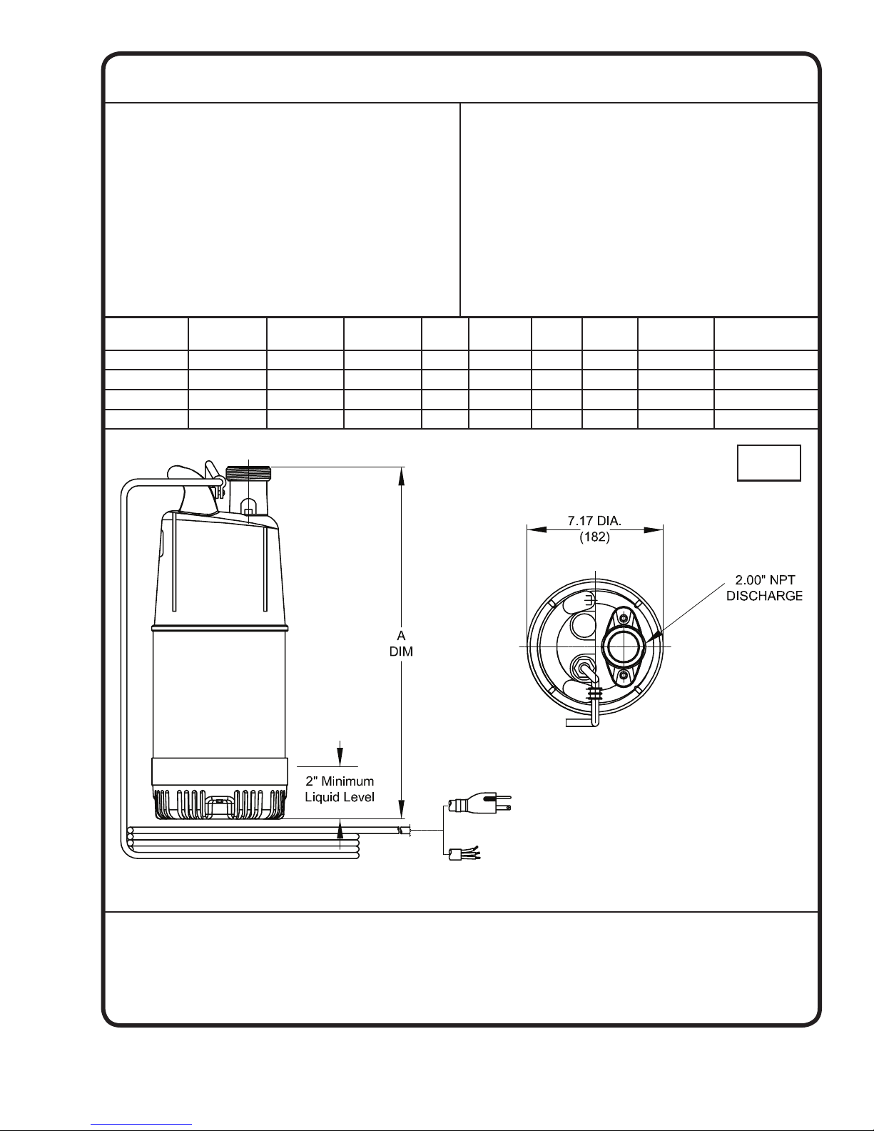
PUMP SPECIFICATIONS:
DISCHARGE ....................... 2” NPT (M), Vertical
LIQUID TEMPERATURE .... 104°F (40°C) Max.
VOLUTE .............................. Non-Metallic
MOTOR SHELL .................. Stainless Steel
IMPELLER .......................... Non-Matallic
SHAFT ................................. 420 Stainless Steel
HARDWARE ....................... 300 Series Stainless Steel
SEAL Design ............. Tandem Mechanical, Oil-Filled
Reservoir
Material:
Stationary Face.Silicon/Carbide, Pump End
Ceramic, Motor End
Rotating Face ... Carbon
CORD ENTRY ..................... 50 Ft. (15m) Cord with Plug on 120
Volt. Molded for strain relief and
compression seal
SPEED ................................ 3450 RPM (Nominal)
MOTOR: Design ............. NEMA Design L-Single Phase,
Air-Filled, Squirrel Cage Induction
Insulation ........ Class F
SINGLE PHASE .................. Capacitor Start and Run
Includes Overload protection in motor
LIFTING ROPE ................... 3/8” (9.7mm) Polypropylene,
25 Ft (7.6m)
STRAINER .......................... .25” (6mm) Openings, Non-Metallic
LIFTING HANDLE ............... Non-Matallic
Elastomer .........Buna-N
Hardware ..........300 series stainless steel
MODEL NO. BARNES
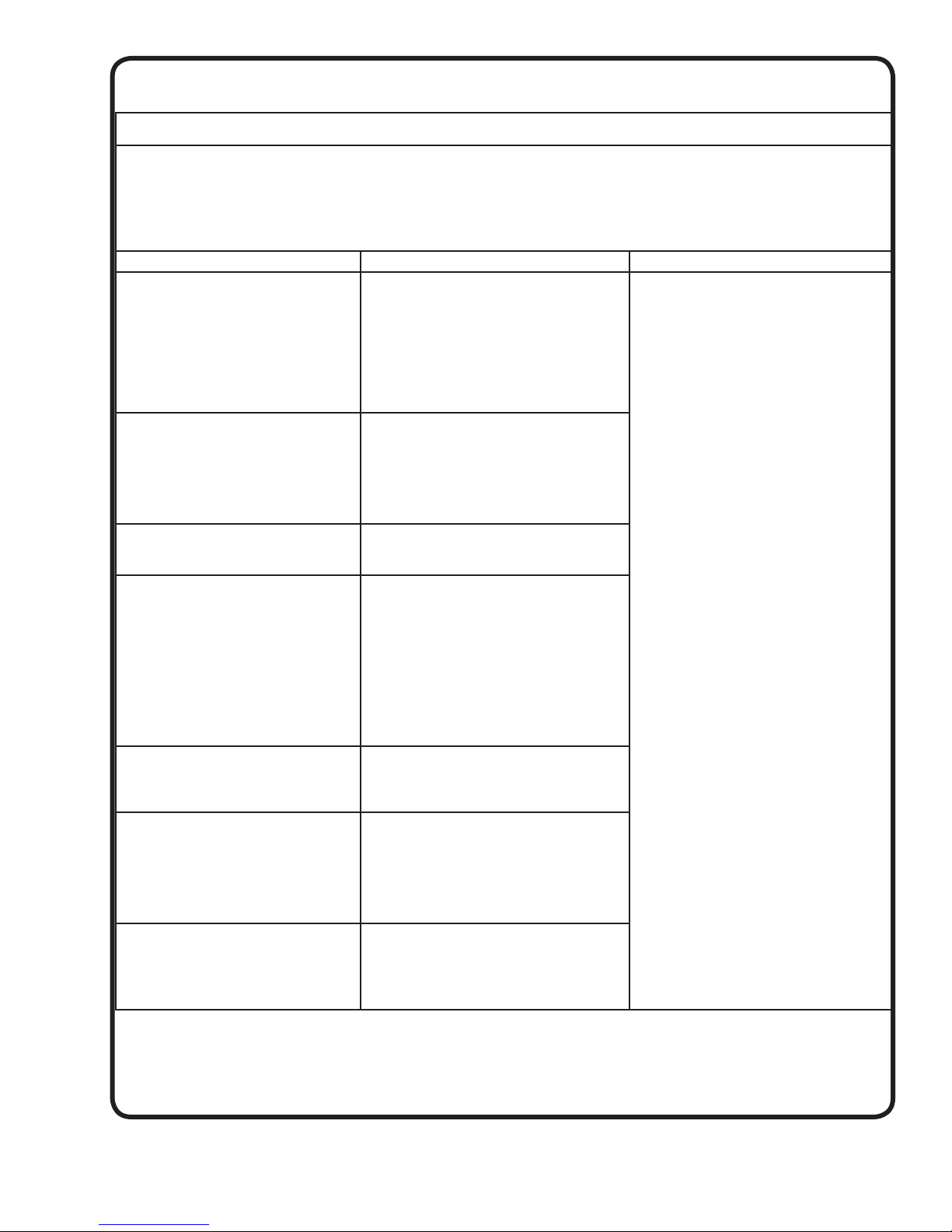
PART NO.
PROSSER
PART NO.
A - Dim
Inch (mm)
HP VOLT PH HERTZ RPM FULL LOAD
70 115070 115165 17.76 (451) 0.7 120 1 60 3450 8.0
71 115071 115166 17.76 (451) 0.7 240 1 60 3450 4.0
125 115125 115167 18.54 (471) 1.25 120 1 60 3450 15.0
126 115126 115168 18.54 (471) 1.25 240 1 60 3450 7.6
AMPS
inches
(mm)
IMPORTANT !
1.)
PUMP MAY BE OPERATED “DRY” FOR EXTENDED PERIODS WITHOUT DAMAGE TO MOTOR AND/OR SEALS.
2.) INSTALLATIONS SUCH AS DECORATIVE FOUNTAINS OR WATER FEATURES PROVIDED FOR VISUAL ENJOYMENT MUST BE INSTALLED IN
ACCORDANCE WITH THE NATIONAL ELECTRIC CODE ANSI/NFPA 70 AND/OR THE AUTHORITY HAVING JURISDICTION. THIS PUMP IS NOT
INTENDED FOR USE IN SWIMMING POOLS, RECREATIONAL WATER PARKS, OR INSTALLATIONS IN WHICH HUMAN CONTACT WITH
PUMPED MEDIA IS A COMMON OCCURRENCE.
Plug On 120 Volt Only
3
Page 4

SECTION B: GENERAL INFORMATION
SECTION C: INSTALLATION
B-1) To the Purchaser:
Congratulations! You are the owner of one of the fi nest
pumps on the market today. CP&S pumps are products
engineered and manufactured of high quality components. Over one hundred years of pump building experience along with a continuing quality assurance program
combine to produce a pump which will stand up to the
toughest applications.
This manual will provide helpful information concerning
installation, maintenance, and proper service guidelines.
B-2) Receiving:
Upon receiving the pump, it should be inspected for damage or shortages. If damage has occurred, fi le a claim
immediately with the company that delivered the pump. If
the manual is removed from the packaging, do not lose or
misplace.
B-3) Storage:
Short Term- CP&S Pumps are manufactured for effi cient
performance following short inoperative periods in storage. For best results, pumps can be retained in storage,
as factory assembled, in a dry atmosphere with constant
temperatures for up to six (6) months.
Long Term- Any length of time exceeding six (6) months,
but not more than twenty-four (24) months. The unit
should be stored in a temperature controlled area, a
roofed over walled enclosure that provides protection
from the elements (rain, snow, wind-blown dust, etc.), and
whose temperature can be maintained between +40 deg.
F and +120 deg. F. (4.4 - 49°C).
Pump should be stored in its original shipping container.
On initial start up, rotate impeller by hand to assure seal
and impeller rotate freely. If it is required that the pump be
installed and tested before the long term storage begins,
such installation will be allowed provided:
1.) The pump is not installed under water for more than
one (1) month.
2.) Immediately upon satisfactory completion of the test,
the pump is removed, thoroughly dried, repacked in
the original shipping container, and placed in a
temperature controlled storage area.
B-4) Service Centers:
For the location of the nearest Barnes or Prosser Center,
check your Barnes or Prosser representative or
Crane Pumps & Systems, Inc., Service Department in
Piqua, Ohio, telephone (937) 778-8947 or Crane Pumps &
Systems Canada, in Brampton, Ontario, (905) 457-6223.
C-1) Location:
These pumps are recommended for general and light
construction, for sump and dewatering drainage, for dewatering manholes and transformer vaults, for pit, tunnel and
trench dewatering, and for fl ood, fi re and other emergency
service cleanup.
Before pumping fl uids other than water, consult the
factory, giving fl uid, fl uid temperature, specifi c gravity,
viscosity, capacity in USGPM and total head and/or pressure requirements, including friction loss through discharge line, fi ttings, valves, etc. Pump may run dry for 5 to
10 minutes in air without damage where air can circulate
freely through the pump. DO NOT allow pump to be buried in mud or sand.
C-2) Discharge:
Discharge hose is recommended. If rigid pipe is used,
install so that there is no weight or strain on the pump.
C-3) Liquid Level Controls: (If Applicable)
Attach “ON” fl oat to discharge hose or pump cable at
desired pump “ON” level. Attach “OFF” fl oat to discharge
hose or pump cable at desired pump “OFF” level. The
“OFF” fl oat must be below the “ON” fl oat. To attach the
fl oats, thread the cable strap through the buckle with
the ratchet pawl, cinch up tight, thread excess strapping
through outer buckle slot. Be certain the level controls
cannot hang up or foul in its swing. It is recommended that
the pump is completely submerged when the level control
is in the “OFF” mode.
C-4.1) Electrical Connections:
The pump comes with a three wire cord and a three prong
grounded plug on the 120 volt models and a three wire cord
without a plug on the 240 volt models.
The 120 volt model’s cord assembly should not be
modifi ed in any way and must be connected into a three
wire grounded Ground Fault receptacle.
There are many different prong confi gurations for 240 volt
applications. An appropriate 240 volt plug to match your
receptacle will be required. Make sure the plug meets the
pump amp requirements found on the nameplate. Follow
the plug manufacturer’s wiring installation instructions.
DO NOT USE THE POWER CABLE TO LIFT PUMP.
C-4.2) Overload Protection:
An automatic thermal overload protects the motor. The
type of in-winding overload protector used is referred to
as an inherent overheating protector and operates on the
combined effect of temperature and current. This means
that the overload protector will trip out and shut the pump
off if the windings become too hot or the current passing
through them becomes too high.
4
Page 5
It will then automatically reset and restart the pump after
the motor cools to a safe temperature. In the event of an
overload, the source of this condition should be determined and rectifi ed immediately. DO NOT LET THE
PUMP CYCLE OR RUN IF AN OVERLOAD CONDITION
OCCURS!
SECTION D - START UP OPERATION
E-4) Fasteners:
All bolts, nuts, screws and other means of fastenings shall
be in place, properly tightened and secured.
E-5) Cable Requirements:
Special care shall be taken in handling the cable (7)
against mechanical injury and wear. Connections and
wiring to the power source shall be in accordance with all
electrical and safety codes.
D-1) Check Pump Rotation:
Before putting pump into service for the fi rst time, the
motor rotation must be checked. This is especially true
on 240 volt pumps after installing the appropriate cable
plug. Improper motor rotation can result in poor pump
performance and can damage the motor and/or pump. To
check the rotation, suspend the pump freely, momentarily
apply power and observe the “kick”. “Kick” should always
be in a counterclockwise direction as viewed from the top
of the pump motor housing. Pump “kick” is the opposite
direction of pump rotation.
D-2) Start Up:
DO NOT attempt to start a frozen pump.
Instead, submerge pump in water for twenty
minutes before starting. DO NOT attempt to
thaw a frozen pump with a torch.
D-3) Warranty Registration:
Fill in the Warranty Registration at the end of this manual
and send it in to our Warranty / Service Department. Also,
record the model number and date code numbers in
Section F-1 of this manual for future reference if needed.
SECTION E - PREVENTATIVE MAINTENANCE
The following procedure must be followed to assure
proper pump operation.
E-1) General Safety:
Frequent inspections shall be made. All electrical parts,
including the portable cable and wiring shall be kept in
a safe condition. KEEP CABLE GLAND NUT TIGHT.
CHECK FREQUENTLY. There shall be no openings in the
casing of the electrical parts. The operating voltage shall
match the voltage rating of the motor.
E-2) Servicing:
Pump shall be restored to the state of original safety with
respect to all lead entrances, etc. following disassembly.
E-3) Renewals and Repairs:
Special care shall be taken in making renewals and repairs. Leave no parts off. Use replacement parts furnished
by the manufacturer. When any lead entrance is disturbed,
the original leads or exact duplicates thereof shall be
used.
E-6) Shaft Seals:
The seals (12 & 16) should be inspected every 400 or
500 operating hours for wear (more often if abrasives are
present). To make a quick check of the seal’s condition,
drain and inspect the oil in the seal chamber (see Section
F1.1). If oil removed from the pump contains water or
abrasives, replace the seals.
SECTION F - SERVICE AND REPAIR
F-1) Lubrication:
F-1.1) Checking Oil - To check the seal chamber oil,
invert the pump and remove the screws (26) lockwashers
(11) strainer (25), suction case (24), impeller nut (15),
washers (14 & 22) and Impeller (21). Remove the socket
head screw (9) with o-ring (8) from the hole marked “OIL”.
With a fl ashlight, visually inspect the oil in the seal cavity
to make sure it is clean and clear, light amber in color and
free from suspended particles. Milky white oil indicates
the presence of water. If the oil looks milky white, pour
the oil out of the oil chamber and let it settle in a clean
dry container. If any water settles out in the bottom of
the container or if the oil is white and thick (emulsifi ed),
replace the mechanical seals and oil.
You can also check oil for contamination by using an oil
tester with a range to 30 Kilovolts breakdown. If oil is
found to be clean and uncontaminated (measure at or
above 15KV. Breakdown), refi ll the seal cavity. If the oil
is found to be dirty, or contaminated (or measures below
15KV. Breakdown), replace the mechanical seals and oil.
F-1.2) Replacing Oil:
Follow steps in E-2.1 to remove socket head screw (9)
with o-ring (8) from the hole marked “OIL”. Turn pump
over to drain oil from seal chamber. Dispose oil properly.
Flush inside seal chamber of diffuser thoroughly to be
sure it is clean and free of abrasives. Refi ll seal chamber
with 3 oz. (90 ml) of an approved oil. The oil shall be of a
highly refi ned paraffi nic base, straight mineral oil, free of
all additives (called non-inhibited or non-detergent). Refer
to Table 1 for recommendations.
5
Page 6
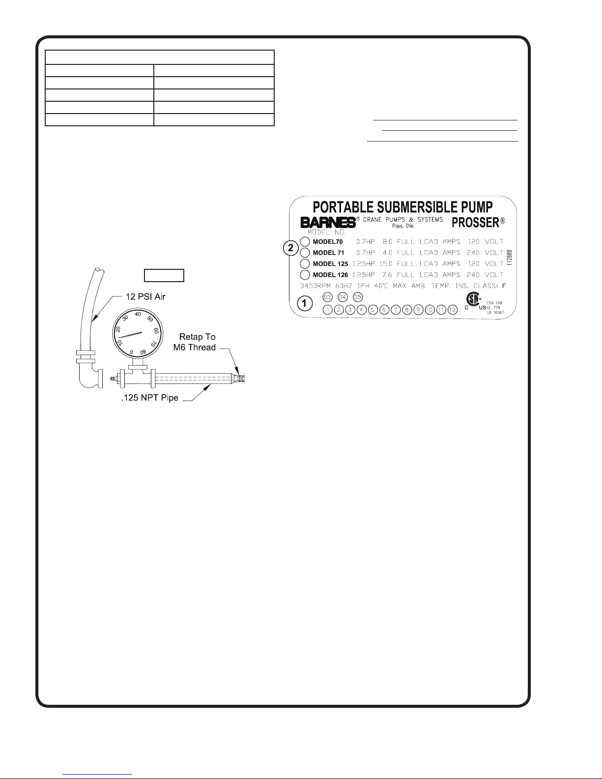
TABLE 1 - COOLING OIL - Dielectric
SUPPLIER GRADE
Shell Turbo oil 32
Texaco Rando HD32
Mobile D.T.E. Oil Light
G & G Oil Circulating 22
F-1.3) Seal Cavity Pressure Test:
Remove the socket head screw (9) and o-ring (8) from
the hole marked “OIL” and check for correct amount of
oil. Apply pipe sealant to pressure gauge assembly and
tighten into hole (See Figure 1). Pressure seal chamber
to 12 PSI and check for leaks. If after fi ve minutes,
the pressure is still holding constant, and no leaks are
observed, slowly bleed the pressure and remove the
gauge assembly. Replace socket head screw (9) with
o-ring (8) using a sealant. If the pressure does not hold,
then the leak must be located and repaired.
Figure 1
SECTION G - WARRANTY REPAIR AND
REPLACEMENT PARTS
G-1) Information Needed:
Always furnish the following information:
1. Pump Part Number
2. Pump Model Number
3. Pump Date Code
NOTE: Record your pump information here for future
reference.
G-2) Part Number:
The Part Number consists of a six (6) digit number, which
appears in the catalog and page 3 of this manual. This
number is used for ordering and obtaining information.
F-2) Impeller Replacement:
Please refer to instructions included with the Repair Parts
Kit.
F-3) Mechanical Seal Replacement:
Please refer to instructions included with the Repair Parts
Kit.
F-4) Power Supply Cord Replacement:
Please refer to instructions included with the Repair Parts
Kit.
F-5) Discharge Nozzle Replacement:
Please refer to instructions included with the Repair Parts
Kit.
F-6) Strainer Replacement:
Please refer to instructions included with the Repair Parts
Kit.
G-3) Model Number:
This designation consists of numbers and letters which
represents the horsepower, motor phase, voltage and
pump design.
G-4) Date Code:
The Date Code consists of two numbers that are punched
holes in the nameplate. This specifi es the month and year
indicating the date the unit was built.
6
Page 7
TROUBLE SHOOTING
CAUTION ! Always disconnect the pump from the electrical power source before handling.
If the system fails to operate properly, carefully read instructions and perform maintenance recommendations.
If operating problems persist, the following chart may be of assistance in identifying and correcting them:
MATCH “CAUSE” NUMBER WITH CORRELATING “CORRECTION” NUMBER.
NOTE: Not all problems and corrections will apply to each pump model.
PROBLEM CA
Pump will not run 1. Poor electrical connection, blown fuse,
Pump will not turn off 2a. Float movement restricted.
Pump hums but does not run 1. Incorrect voltage
Pump delivers insuffi cient capacity 1. Incorrect voltage.
Pump cycles too frequently or runs
periodically when fi xtures are not in use
Pump shuts off and turns on independent of switch, (trips thermal overload
protector). CAUTION! Pump may start
unexpectedly. Disconnect power supply.
Pump operates noisily or vibrates
excessively
tripped breaker or other interruption of power,
improper power supply.
2. Motor or switch inoperative (to isolate
cause, go to manual operation of pump).
2a. Float movement restricted.
2b. Switch will not activate pump or is defective.
3. Insuffi cient liquid level.
2b. Switch will not activate pump or is defec-
tive.
4. Excessive infl ow or pump not properly sized
for application.
9. Pump may be airlocked.
14. H-O-A switch on panel is in “HAND” position
8. Impeller jammed or loose on shaft, worn or
damaged, impeller cavity or inlet plugged.
4. Excessive infl ow or pump not properly sized
for application.
5. Discharge restricted.
6. Check valve stuck closed or installed
backwards.
7. Shut-off valve closed.
8. Impeller jammed or loose on shaft, worn or
damaged, impeller cavity or inlet plugged.
9. Pump may be airlocked.
10. Pump stator damaged/torn.
6. Check valve stuck closed or installed
backwards.
11. Fixtures are leaking.
15. Ground water entering basin.
1. Incorrect voltage.
4. Excessive infl ow or pump not properly sized
for application.
8. Impeller jammed or loose on shaft, worn or
damaged, impeller cavity or inlet plugged
12. Excessive water temperature (Internal
protection only).
2c. Worn bearings, motor shaft bent
8. Debris in impeller cavity or broken impeller.
10. Pump running backwards.
13. Piping attachments to buiding structure too
rigid or too loose.
USE CORRECTION
1. Check all electrical connections for
security. Have electrician measure current
in motor leads, if current is within ±20%
of locked rotor Amps, impeller is probably
locked. If current is 0, overload may be
tripped. Remove power, allow pump to cool,
then recheck current.
2a. Reposition pump or clean basin as
required to provide adequate clearance for
fl oat.
2b. Disconnect level control. Set ohmmeter
for a low range, such as 100 ohms full scale
and connect to level control leads. Actuate
level control manually and check to see that
ohmmeter shows zero ohms for closed switch
and full scale for open switch. (Float Switch).
2c. Check winding insulation (Megger Test)
and winding resistance. If check is outside
of range, dry and recheck. If still defective,
replace per service instructions.
3. Make sure liquid level is at least equal to
suggested turn-on point.
4. Recheck all sizing calculations to
determine proper pump size.
5. Check discharge line for restrictions,
including ice if line passes through or into
cold areas.
6. Remove and examine check valve for
proper installation and freedom of operation.
7. Open valve.
8. Check cutter for freedom of operation,
security and condition. Clean cutter and inlet
of any obstruction.
9. Loosen union slightly to allow trapped air
to escape.Verify that turn-off level of switch
is set so that the suction is always fl ooded.
Clean vent hole.
10. Check rotation. If power supply is three
phase, reverse any two of three power supply
leads to ensure proper impeller rotation.
11. Repair fi xtures as required to eliminate
leakage.
12. Check pump temperature limits & fl uid
temperature.
13. Replace portion of discharge pipe with
fl exible connector.
14. Turn to automatic position.
15. Check for leaks around basin inlet and
outlets.
7
Page 8
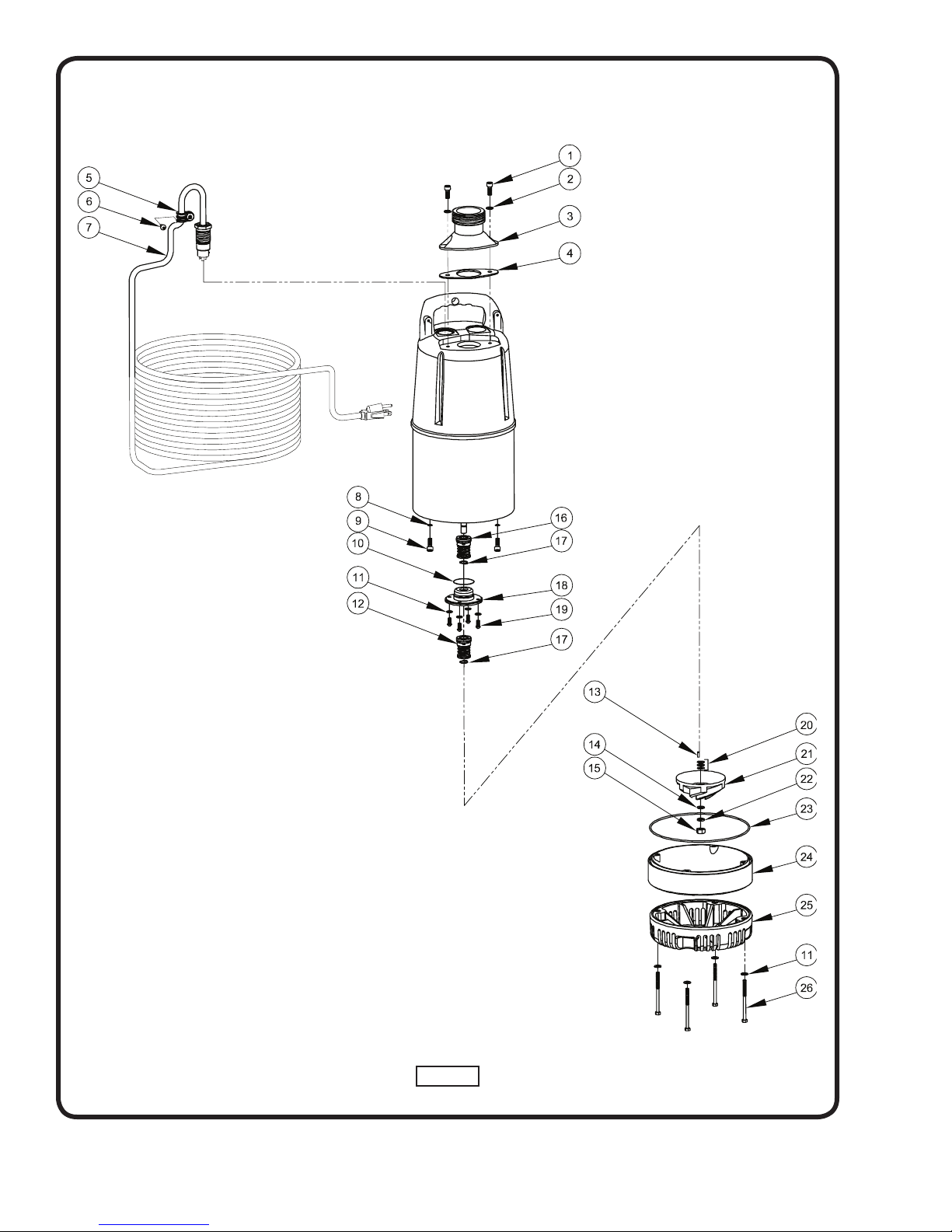
Figure 2
8
Page 9
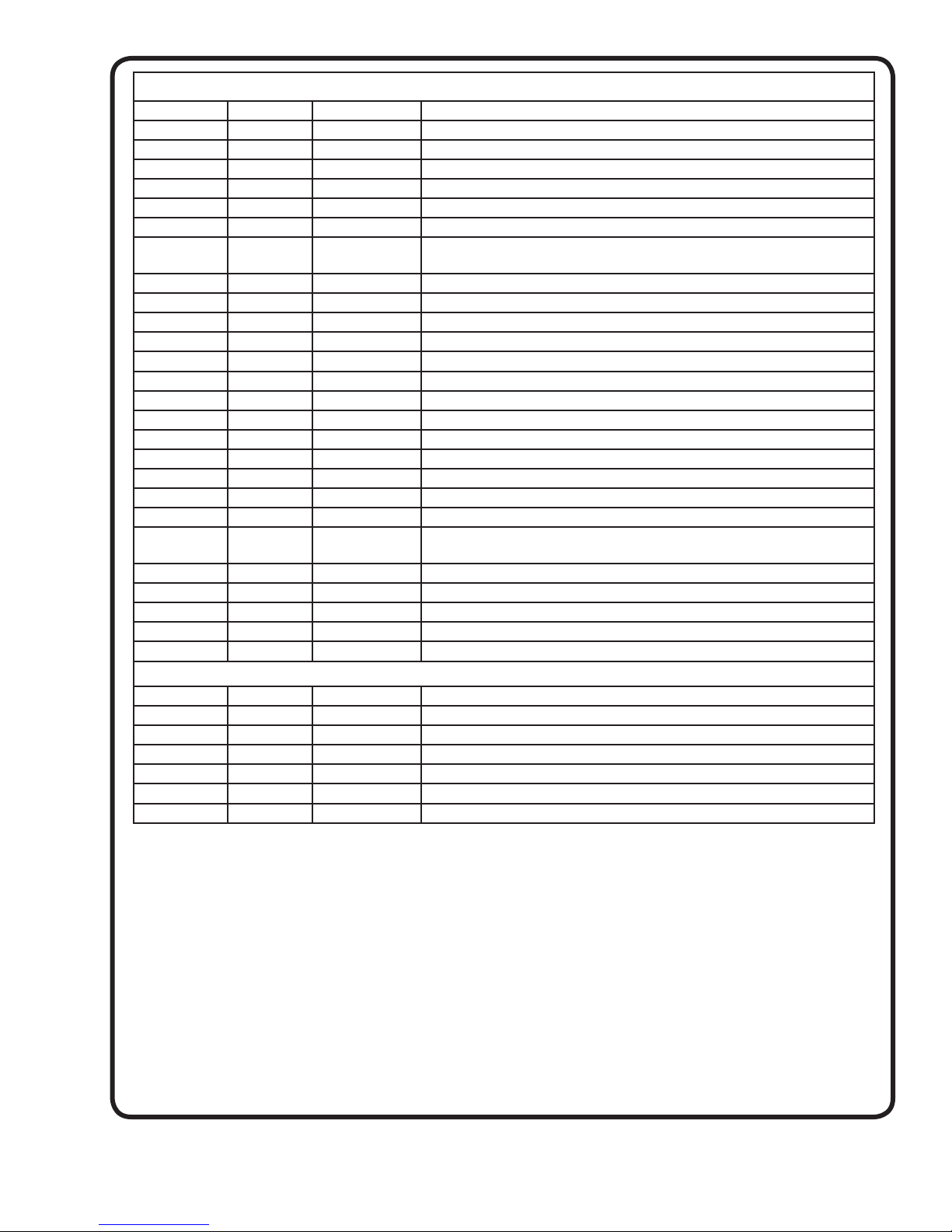
PARTS LIST
ITEM QTY PART NO. DESCRIPTION
1 2 115084 SkHd Screw, M6 x 15, SS
2 2 115085 Flatwasher, 6mm, SS
3 1 115083 Discharge Outlet, 2” NPT
4 1 115086 Discharge Gasket
5 1 115081 Cable Clamp
6 1 115082 Self-Tapping Screw M4.8 x 16, SS
7 1 115078
115079
8 2 115131 O-ring 6mm Dia. x 1.9mm
9 2 115130 SkHd Screw M6 x 10, SS
10 1 115124 O-ring 35mm Dia. x 3.1mm
11 8 115138 Flatwasher 5mm, SS
12 1 130825 Mechanical Seal
13 1 115140 Impeller Key, 3mm x 10mm, SS
14 1 115142 Flatwasher 8mm, SS
15 1 115141 Hex Nut, 8mm, SS
16 1 068988 Mechanical Seal
17 2 115106 Snap Ring
18 1 Seal Plate
19 4 115135 RdHd Screw, M5 x 10, SS
20 3 115139 Impeller Shim
21 1 115121
115122
22 1 115143 Lockwasher, 8mm, SS
23 1 115103 O-ring, 170mm Dia. x 2.5mm
24 1 115137 Suction Case
25 1 115145 Suction Strainer
26 4 115144 Screw, M5 x 72, SS
Cable, w/Plug 120 Volt
Cable w/o Plug 240 Volt
0.7 HP (70 & 71 Series) Impeller
1.25 HP (125 & 126 Series) Impeller
REPAIR PARTS KITS
115073 120 Volt Cord Kit - Items 5, 6 & 7
115074 240 Volt Cord Kit - Items 5, 6 & 7
115075 Discharge Nozzle Kit - Items 1, 2, 3 & 4
115077 Strainer Kit - Items 11, 25 & 26
115072 0.7 HP Impeller Kit - Items 13, 14, 15, 20, 21, 22 & 24
115127 1.25 HP Impeller Kit - Items 13, 14, 15, 20, 21, 22 & 24
115076 Mechanical Seal Kit - Items 8, 9, 10, 11, 12, 16, 17 & 19
Repair parts are available in REP
procedures and illustrations to assist in replacement of the necessary parts
AIR PARTS KITS ONLY. Each kit contains an instruction sheet with
9
Page 10
A Crane Co. Company
Limited 24 Month Warranty
Crane Pumps & Systems warrants that products of our manufacture will be free of defects in material and workmanship
under normal use and service for twenty-four (24) months after manufacture date, when installed and maintained
in accordance with our instructions.This warranty gives you speci• c legal rights, and there may also be other rights
which vary from state to state. In the event the product is covered by the Federal Consumer Product Warranties Law
(1) the duration of any implied warranties associated with the product by virtue of said law is limited to the same
duration as stated herein, (2) this warranty is a LIMITED WARRANTY, and (3) no claims of any nature whatsoever
shall be made against us, until the ultimate consumer, his successor, or assigns, noti• es us in writing of the defect,
and delivers the product and/or defective part(s) freight prepaid to our factory or nearest authorized service station.
Some states do not allow limitations on how long an implied warranty lasts, so the above limitation may not apply.
THE SOLE AND EXCLUSIVE REMEDY FOR BREACH OF ANY AND ALL WARRANTIES WITH RESPECT TO ANY
PRODUCT SHALL BE TO REPLACE OR REPAIR AT OUR ELECTION, F.O.B. POINT OF MANUFACTURE OR
AUTHORIZED REPAIR STATION, SUCH PRODUCTS AND/OR PARTS AS PROVEN DEFECTIVE. THERE SHALL BE
NO FURTHER LIABILITY, WHETHER BASED ON WARRANTY, NEGLIGENCE OR OTHERWISE. Unless expressly
stated otherwise, guarantees in the nature of performance speci• cations furnished in addition to the foregoing material
and workmanship warranties on a product manufactured by us, if any, are subject to laboratory tests corrected for
• eld performance. Any additional guarantees, in the nature of performance speci• cations must be in writing and such
writing must be signed by our authorized representative. Due to inaccuracies in • eld testing if a con! ict arises between
the results of • eld testing conducted by or for user, and laboratory tests corrected for • eld performance, the latter
shall control. RECOMMENDATIONS FOR SPECIAL APPLICATIONS OR THOSE RESULTING FROM SYSTEMS
ANALYSES AND EVALUATIONS WE CONDUCT WILL BE BASED ON OUR BEST AVAILABLE EXPERIENCE AND
PUBLISHED INDUSTRY INFORMATION. SUCH RECOMMENDATIONS DO NOT CONSTITUTE A WARRANTY OF
SATISFACTORY PERFORMANCE AND NO SUCH WARRANTY IS GIVEN.
This warranty shall not apply when damage is caused by (a) improper installation, (b) improper voltage (c) lightning
(d) excessive sand or other abrasive material (e) scale or corrosion build-up due to excessive chemical content. Any
modi• cation of the original equipment will also void the warranty. We will not be responsible for loss, damage or labor
cost due to interruption of service caused by defective parts. Neither will we accept charges incurred by others without
our prior written approval.
This warranty is void if our inspection reveals the product was used in a manner inconsistent with normal industry practice
and\or our speci• c recommendations. The purchaser is responsible for communication of all necessary information
regarding the application and use of the product. UNDER NO CIRCUMSTANCES WILL WE BE RESPONSIBLE FOR
ANY OTHER DIRECT OR CONSEQUENTIAL DAMAGES, INCLUDING BUT NOT LIMITED TO TRAVEL EXPENSES,
RENTED EQUIPMENT, OUTSIDE CONTRACTOR FEES, UNAUTHORIZED REPAIR SHOP EXPENSES, LOST
PROFITS, LOST INCOME, LABOR CHARGES, DELAYS IN PRODUCTION, IDLE PRODUCTION, WHICH DAMAGES
ARE CAUSED BY ANY DEFECTS IN MATERIAL AND\OR WORKMANSHIP AND\OR DAMAGE OR DELAYS IN
SHIPMENT. THIS WARRANTY IS EXPRESSLY IN LIEU OF ANY OTHER EXPRESS OR IMPLIED WARRANTY,
INCLUDING ANY WARRANTY OF MERCHANTABILITY OR FITNESS FOR A PARTICULAR PURPOSE.
No rights extended under this warranty shall be assigned to any other person, whether by operation of law or otherwise,
without our prior written approval.
420 Third Street 83 West Drive
Piqua, Ohio 45356 Brampton, Ont. Canada L6T 2J6
(937) 778-8947 (905) 457-6223
Fax (937) 773-7157 Fax (905) 457-2650
www.cranepumps.com
Page 11
RETURNED GOODS
RETURN OF MERCHANDISE REQUIRES A “RETURNED GOODS AUTHORIZATION”.
CONTACT YOUR LOCAL CRANE PUMPS & SYSTEMS, INC. DISTRIBUTOR.
Products Returned Must Be Cleaned, Sanitized,
Or Decontaminated As Necessary Prior To Shipment,
To Insure That Employees Will Not Be Exposed To Health
Hazards In Handling Said Material. All Applicable Laws
And Regulations Shall Apply.
IMPORTANT!
WARRANTY REGISTRATION
Your product is covered by the enclosed Warranty.
To complete the Warranty Registration Form go to:
http://www.cranepumps.com/ProductRegistration/
If you have a claim under the provision of the warranty, contact your local
Crane Pumps & Systems, Inc. Distributor.
Page 12

Notes
 Loading...