

Barmesa Pumps 2AHS051, 2AHS101A, 2AHS051A, 2AHS101, 2AHS103 Installation, Operation & Maintenance Manual
...Page 1
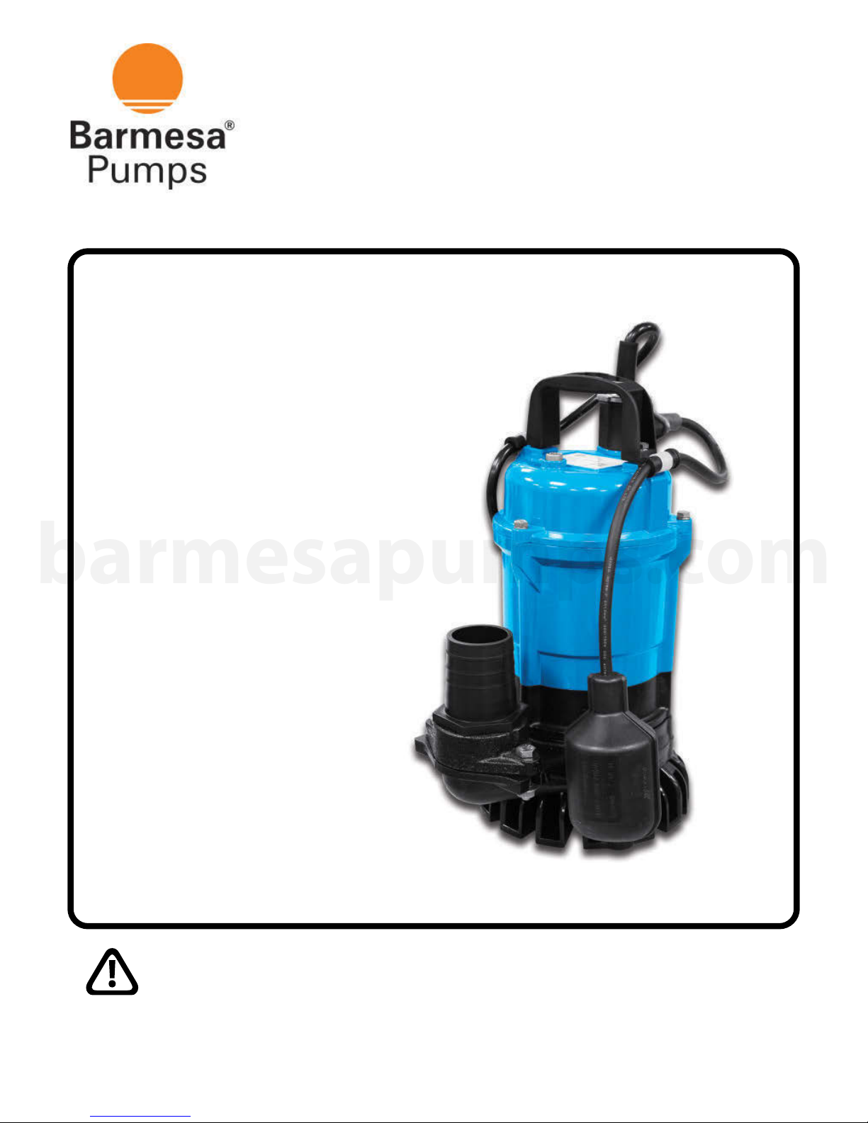
2AHS
0.5, 1 & 2 HP
@ 3500 RPM
Installation, Operation &
Maintenance Manual
Submersible Dewatering Pumps
barmesapumps.com
IMPORTANT! - Read all instructions in this manual before operating or servicing
a pump.
Page 2
General Safety Information
Before installation, read the following
instructions carefully. Failure to
follow instruction and safety
information could cause serious
bodily injury, death and/or property
damage. Each Barmesa product is
carefully inspected to insure proper
performance. Closely following these
instructions will eliminate potential
operating problems, assuring years
of trouble-free service.
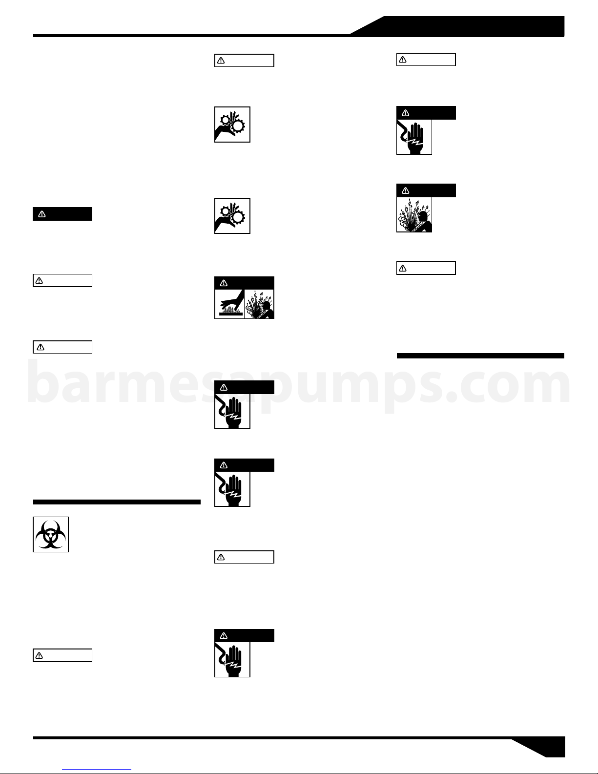
DANGER
nently hazardous situation which, if
not avoided, WILL result in death or
serious injury.
WARNING
nenty hazardous situation which, if
not avoided, MAY result in death or
serious injury.
CAUTION
hazardous situation which, if not
avoided, MAY result in minor or
moderate injury.
Indic ates an i mmi-
Indicate s an immi-
Indicates a potentially
barmesapumps.com
IMPORTANT! - Barmesa Pumps is not
responsible for losses, injury or
death resu lting from fai lure to
observe these safety precautions,
misuse, abuse or misapplication of
pumps or equipment.
A L L R E T U R N E D
P R O D U C T S M U S T B E
CLEANED, SANITIZED, OR
DECONTA M I N AT ED P RIOR TO
SHIPMENT, TO INSURE EMPLOYEES
WILL NOT BE EXPOSED TO HEALTH
HAZA RD S IN HAN DLING S AID
MATERIAL. ALL APPLICABLE LAWS
AND REGULATIONS SHALL APPLY.
WARNING
junc tio n co nne ct ion s must be in
accordance with the National Electric
Code and all applicable state and local
codes. Requirements may vary depending
on usage and location.
Installation, wiring, and
WARNING
se rvicing is to be conducted by
qualified personnel only.
power connected; the rotating cutter
and/or impeller can cause serious
injuty.
may become entangled in moving
parts.
DANGER
before handling or servicing the
p u m p o r a ny accessory i t e m s
associated with or near the pump.
DANGER
human contact with pumped fluid.
DANGER
handling any aspect of the pumping
system. Lock out power & tag.
WARNING
pumps in water over 104 °F. Do not
exceed manufactures recommended
maximum performance, as this could
cause the motor to overheat.
DANGER
shock, burns or death. Never handle
connected power cords with wet
hands. Use appropriate lifting device.
I n s t a l l a t i o n a n d
Keep clear of suction and
discharge openings. Do not
insert fingers in pump with
Always wear eye protection
when working on pumps. Do
not wear loose clothing that
Pumps build up heat
and pressure during
operation. Allow time
fo r p umps t o c ool
T h i s p u m p i s n o t
i n t e n d e d f o r u s e i n
swimming pools or water
installations where there is
Risk of electric shock. To
reduce risk of electric shock,
always disco nnect pump
from power source before
D o n o t u se t h e se
Do not lift, carry or
hang pump by the electrical
c a b l e s . D amage to t h e
electrical cables can cause
WARNING
Interrupter (GFCI) to be used with
plug-in type power cord.
DANGER
burns or death.
DANGER
Electric Code, ANSI/NFPA 70.
WARNING
Code (UP C) s tat es that sew age
systems shall have an audio and visual
alarm that signals a malfunction of the
systems, that are required to reduce
the potencial for property damage.
IMPORTANT! - Prior to installation,
record Model Number, Serial, Amps,
Voltage, Phase and HP from pump
name plate for the future reference.
Also record the Voltage and Current
Readings at Startup:
Model Number:_____________________
Serial:_____________________________
Amps:___________ Volts:____________
Phase:____________ HP:_____________
Ground Fault Circuit
Failure to permanently
ground the pump, motor and
controls before connecting
to power can cause shock,
These pumps are not to
be i nstal led in l ocati ons
classified as hazardous in
accordance with the National
The Uniform Plumbing
01
Page 3
Specifications & Dimensions
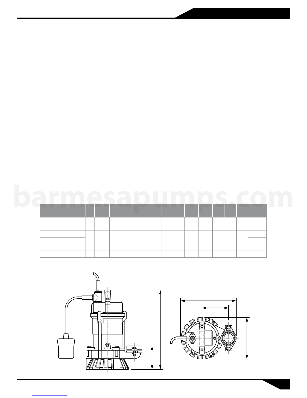
DISCHARGE: 2" NPT, vertical, adapter included.
SPHERICAL SLD HNDLG: 1/2"
LIQUID TEMPERATURE: 104 °F (40 °C) max.
PUMP BODY: Cast iron FC-200.
MOTOR HOUSING: Aluminum alloy ADC12.
OIL CHAMBER: Cast iron FC-200.
IMPELLER: 8 vane, semi-open Vortex. Hytrel® thermoplastic elastomer.
SHAFT: 410 series stainless steel.
HARDWARE: 304 series stainless steel.
O-RINGS: .Nitrile rubber (NBR)
PAINT: Air dry enamel, water based.
SEAL: Double mechanical, oil filled chamber. Upper part of carbon-ceramic, lower part of
silicone carbide. Stainless steel hardware.
CORD ENTRY: 15 ft of neoprene cord , sealed against moisture.
BEARINGS: Ball, single row, permanently oil lubricated for 60,000 hours of work. Designed for
radial and axial loads.
MOTOR: Dry type submersible motor, 1 & 3 phase, 115 & 230 volts, 60 Hz, 3500 RPM. For
continuous duty, with thermal protector IP68 in winding, insulation class B.
STRAINER: Polyvinyl chloride (PVC).
HANDLE: Nylon 6.
PUMP OPERATION: Available as "A" Automatic model or Manual operation (no level control).
barmesapumps.com
MODEL PART No. HP VOLTS PHASE
2AHS051 62180101 27
2AHS051A 62180102 28
2AHS101 62180103 33
2AHS101A 62180104 34
2AHS103 70090005 1 230 3 3500 3 16 AWG/3C 14.84" 10.98" Ø7" 4.75" 5,24" 34
2AHS203 70090007 2 230 3 3500 7 14 AWG/3C 18.27" 12.32" Ø7.5" 5.13" 6.1" 42
A = Automatic Float Switch. A control panel is needed for the 3 phase pumps to operate in automatic.
115
1
1
RPM
(Nominal)
3500 6 16AWG/3C 13.86" 9.57"0.51115
MAX
AMPS
CORD
SIZE
AAA
A B C D E
Ø7" 4.25" 4.61"
10.98"14.84"16 AWG/3C123500
BBB
EEE
WEIGHT
(pounds)
5.24"4.75"Ø7"
CCC
DDD
02
Page 4
Installation
Receiving inspection
Upon receiving the pump, it should
be inspected for damage or
shortages. If damage has occurred,
file a claim immediately with the
company that delivered the pump. If
the manual is removed from the
packaging, do not lose or misplace.
Storage
Any product that is stored for a
period longer than six (6) months
from the date of purchase should be
bench tested prior to installation. A
bench test consists of, checking the
impeller to assure it is free turning
and a run test to assure the motor
(and switch if provided) operate
properly.
Before Installation
Insulation resistance measurement
With the motor and cable (excluding
the power supply cable) immersed in
water, use a megger to measure the
insulation resistance between
ground and each phase of the motor,
and again between each phase of the
barmesapumps.com
motor. The megger should indicate
an insulation resistance of not less
than 20 mega ohms. While making
the measurement, keep the power
supply cable off the ground. We
recommend that an auxiliary
pump be kept on hand in case of
emergency.
Installation
WARNING
should cable be pulled while the
pump is bein g t r ansporte d o r
installed. Attach a chain or rope to the
grip and install the pump.
1.This pump must not be installed
on its side or operated in a dry
condition. Ensure that it is
installed upright on a secure base.
2.Install the pump at a location in
the tank where there is the least
turbulence.
Under no circumstances
3.If there is a flow of liquid inside
the tank, support the piping
where appropriate. Install piping
so that air will not be entrapped. If
piping must be installed in such a
way that air pockets are
unavoidable, install an air release
valve wherever such air pockets
are most likely to develop.
4.Do not permit end of discharge
piping to be submerged, as
backflow will result when the
pump is shut down.
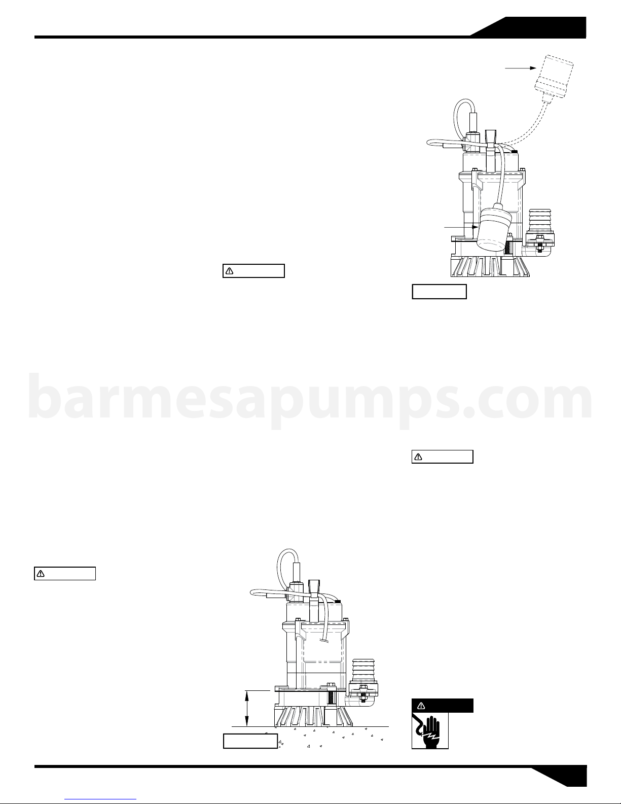
WARNING
(models 2AHS), have an automatic
operating system bump operating
water leve l n e ar the minim um
operating level as the automatic cutoff switch incorporated inside the
motor will be activated. To avoid dry
oper atio n, ins ta ll an auto m atic
operating system, as shown in Figure 1
and maintain a safe operating water
level (C.W.L.: continuous water level =
90 mm).
5.For automatic pumps (models
2AHS-A), install the floats as
shown in figure 2. The pump may
not start if a floats switch touches
the wall of the water tank or the
piping. Install the floats so that
this will not happen.
C.W.L.
Figure 1
Non-automatic pumps
ON
OFF
Figure 2
Wiring:
a) Wire as indicated for the
appropiate start system as shown
in figure 3.
b) Loose connections will stop the
pump. Make sure all electrical
connections are secure.
Cable:
WARNING
the cable contact water.
d) If the cable is extended, do not
immerse the splice in water.
e) Fasten the cable to the discharge
piping with tape or vinyl strips.
f) Install the cable so that it will not
overheat. Overheating caused by
coiling the cable and exposing it to
direct sunlight.
Grounding:
Connect the green wire to ground.
Under no circumstances should the
green wire be connected to the
power supply.
DANGER
c) Never let the end of
U s e s h o r t c i r c u i t
breakers to prevent danger of
electrical shock.
03
Page 5
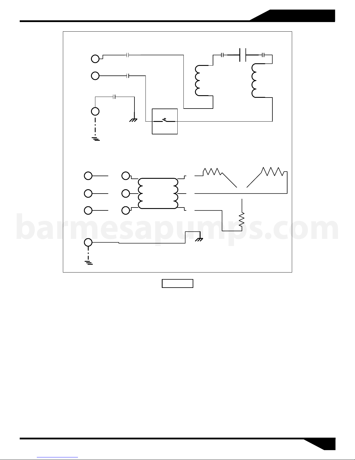
Single phase
Electrical Wiring
Capacitor
Black
(Brown)
White
(Blue)
Green
(Green/Yellow)
Frame
Grounding
Ground
Three phase
Black
R
(Black)
White
S
(Blue)
T
Red
(Brown)
barmesapumps.com
(Green/Yellow)
Ground
U
V
W
Green
Protector
U2
V2
W2
Grounding
Frame
Main
Coil
Starting
Coil
Overload
Protector
Figure 3
04
Page 6
Operation & Maintenance
Before Starting the Pump
1) After completing installation,
measure the insulation resistance
again as described in Installation.
2) Check water level. If the pump is
operated continuously for an
extended period of time in a dry
condition or at the lowest water
level, the motor protector will be
activated. Constant repetition of
this action will shorten pump
service life. Do not start the pump
again in such a situation until
after the motor has completely
cooled.
Test operation
Automatic (2AHS-A) and nonautomatic (2AHS) pump:
1) Turn the operating switch on and
off a couple of times to check for
normal pump start.
For the 2AHS-A:
Floating switch must be raised for
the pump to start.
2) Next, check direction and rotation.
barmesapumps.com
If discharge volume is low or
unusual sounds are heard when
the pump is operating, rotation
has been reversed. When this
happens, reverse two of the wires.
Monthly inspections:
Measure the insulation resistance.
The value should be more than 1M
ohm. If resistance starts to fall rapidly
even with an initial indication of over
1M ohm, this may be an indication of
trouble and repair work is required.
Annual inspections:
To extend the service life of the
mechanical seal, replace the oil in the
mechanical seal chamber once a
year. Water mixed with the oil or
cloudy textures are indications of a
defective mechanical seal requiring
replacement. When replacing the oil,
lay the pump on its side with filler
plug on top. Inject suitable amount
turbine oil no. 32 (ISO VG-32).
Inspections at 3-5 year intervals:
Conduct an overhaul of the pump.
These intervals will preclude the
possibility of future trouble.
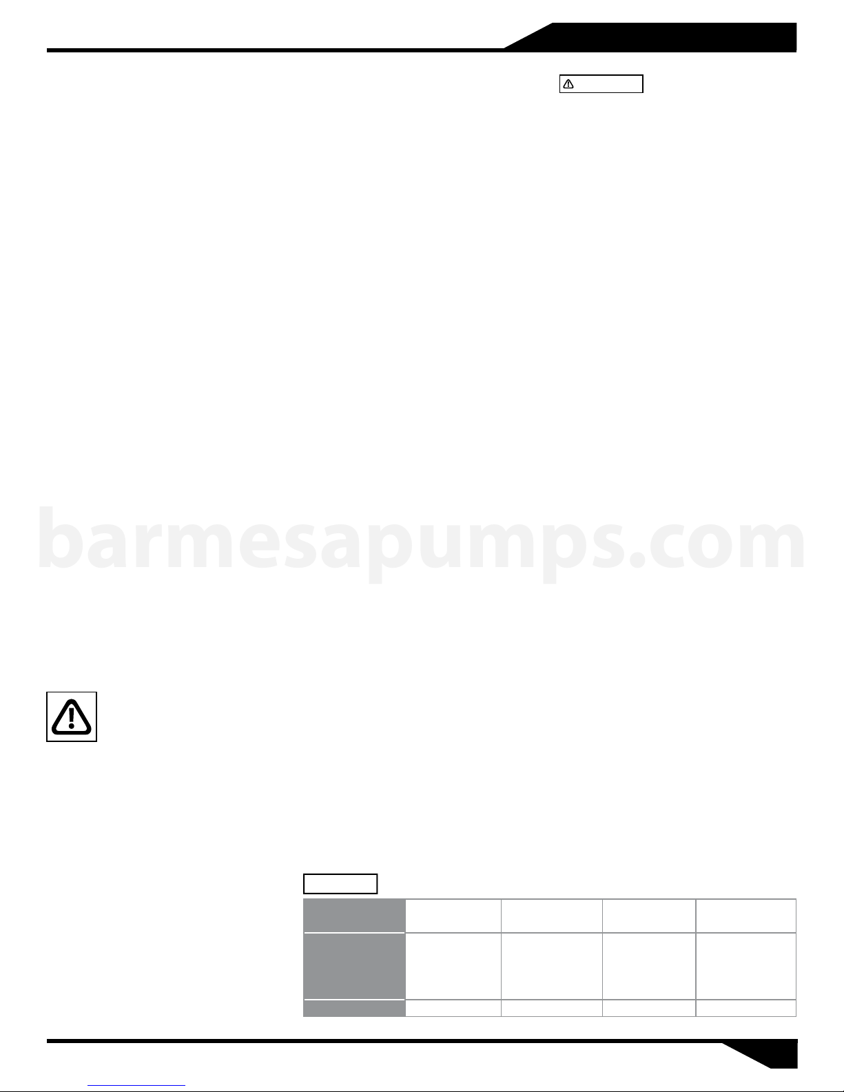
Parts that will need to be replaced:
Replace the appropriate part when
the following conditions are
apparent. See figure 4. (Note:
replacement schedule is based on
normal operating conditions)
Disassembly
Maintenance
Check pressure, output,
voltage, current and other
specifications. Unusual
readings may indicate. Refer to
Troubleshooting and correct as
soon as possible.
Daily inspections:
1) Check current and ammeter
fluctuation daily. If ammeter
fluctuation is great, even though
within the limits of pump rating,
foreign matter may be clogging
the pump. If the quantity of liquid
discharged falls suddenly, foreign
matter may be blocking the
suction inlet.
When disassembling pump, have a
piece of cardboard or wooden board
ready to place the different parts on
as you work. Do not pile parts on top
of each other. They should be laid out
neatly in rows. The o-ring and gasket
cannot be used again once they are
removed. Have replacement parts
ready. Disassemble in the following
order, referring to the sectional view.
Figure 4
REPLACEABLE
PART
REPLACEAMENT
GUIDE
FREQUENCY Annually Every 6 months Every 6 months Annually
Mechanical seal
Whenever oil in
mechanical seal
chamber is
clouded
Oil filler plug
gasket
Whenever oil is
replaced or
inspected
WARNING
source before disassembly.
1. Remove pump casing bolts, raise
the motor section and remove pump
casing.
2. Remove shaft head bolt and
impeller.
3. Remove oil filler plug and drain
lubricating oil.
4. Remove intermediate casing bolts
and intermediate oil chamber.
(Remember that any lubricating oil
remaining in the mechanical seal
chamber will flow out.)
5. Carefully remove mechanical seal,
taking care not to scratch sliding
surface or motor shaft.
Be sure to cut off power
Assembly
Re-assemble in reverse order of
disassembly. Be careful of the
following points:
6. During re-assembly, rotate the
impeller by hand and check for
smooth rotation. If rotation is not
smooth, perform steps (3) through
(5) again.
7. Upon completion of re-assembly
step 1 rotate the impeller by hand
from the suction the suction inlet
and check that it rotates smoothly
without touching the suction cover
before operating the pump.
Please obtain o-rings, packing, shaft
seals and other parts from pump
dealer.
Lubricating oil O-ring
Whenever
clouded or dirty
Whenever pump
is overhauled
05
Page 7
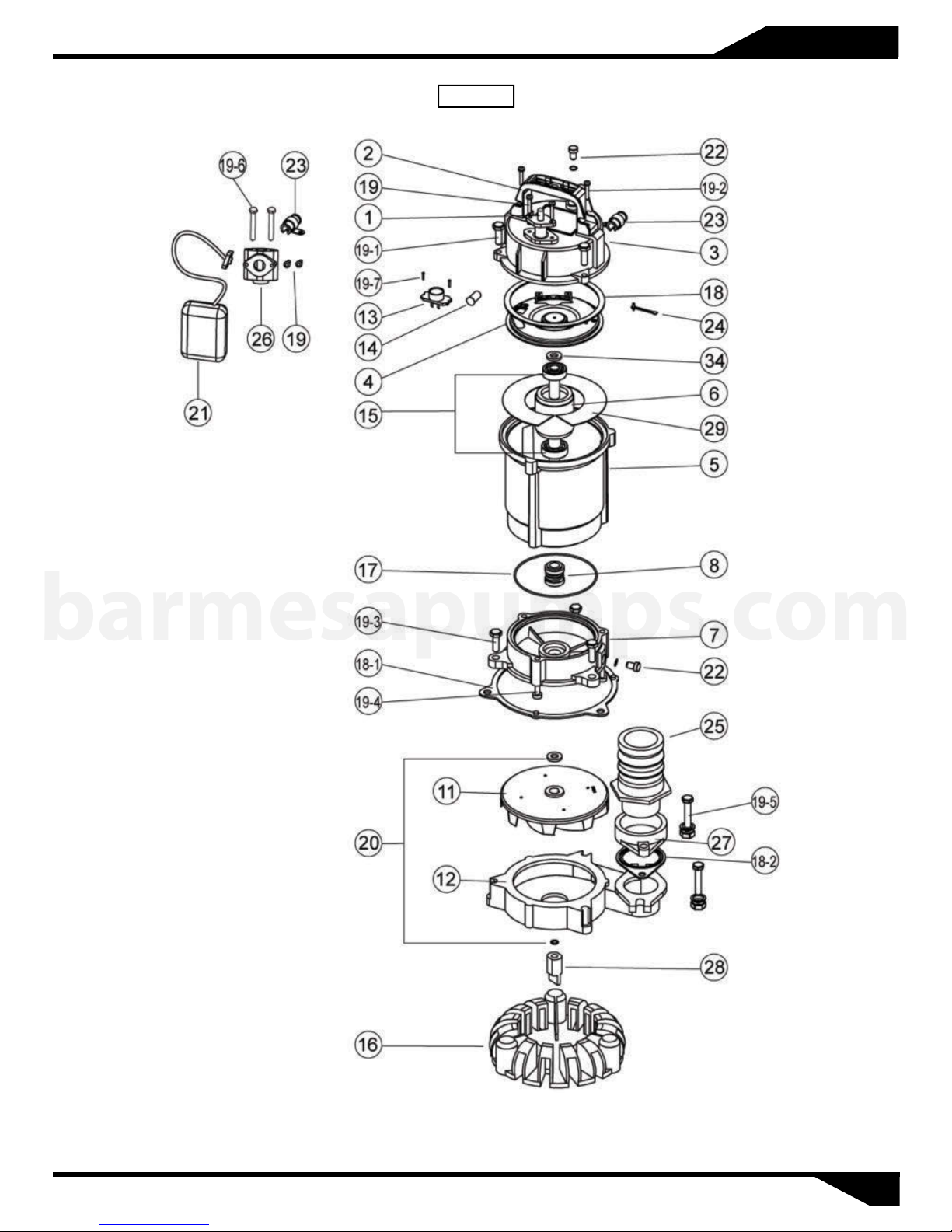
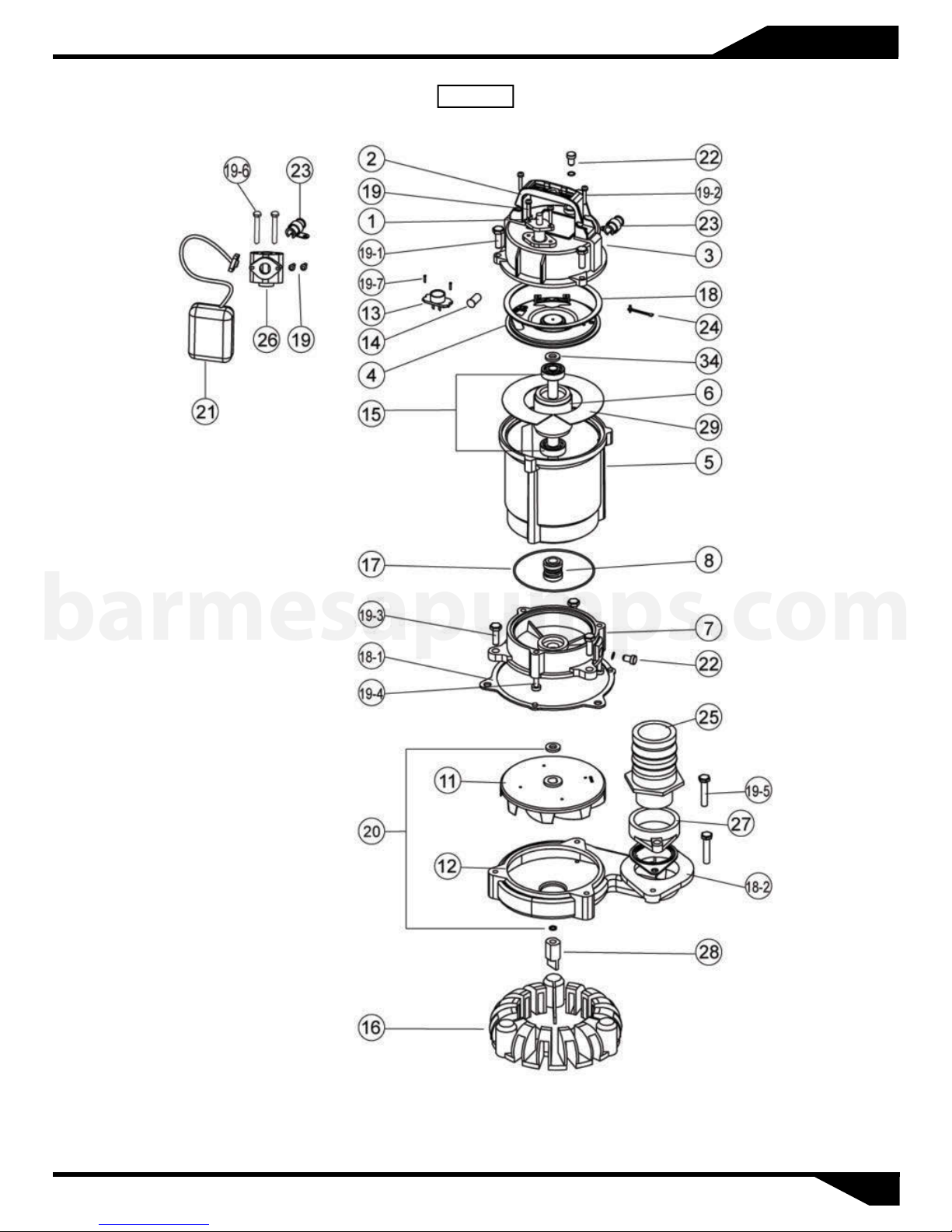
2AHS 0.5 HP
Repair Parts
Figure 5
barmesapumps.com
For repair part please supply: Model Number and Serial as shown on Name Plate, and Part Description and Part Number as shown
on Parts List.
06
Page 8
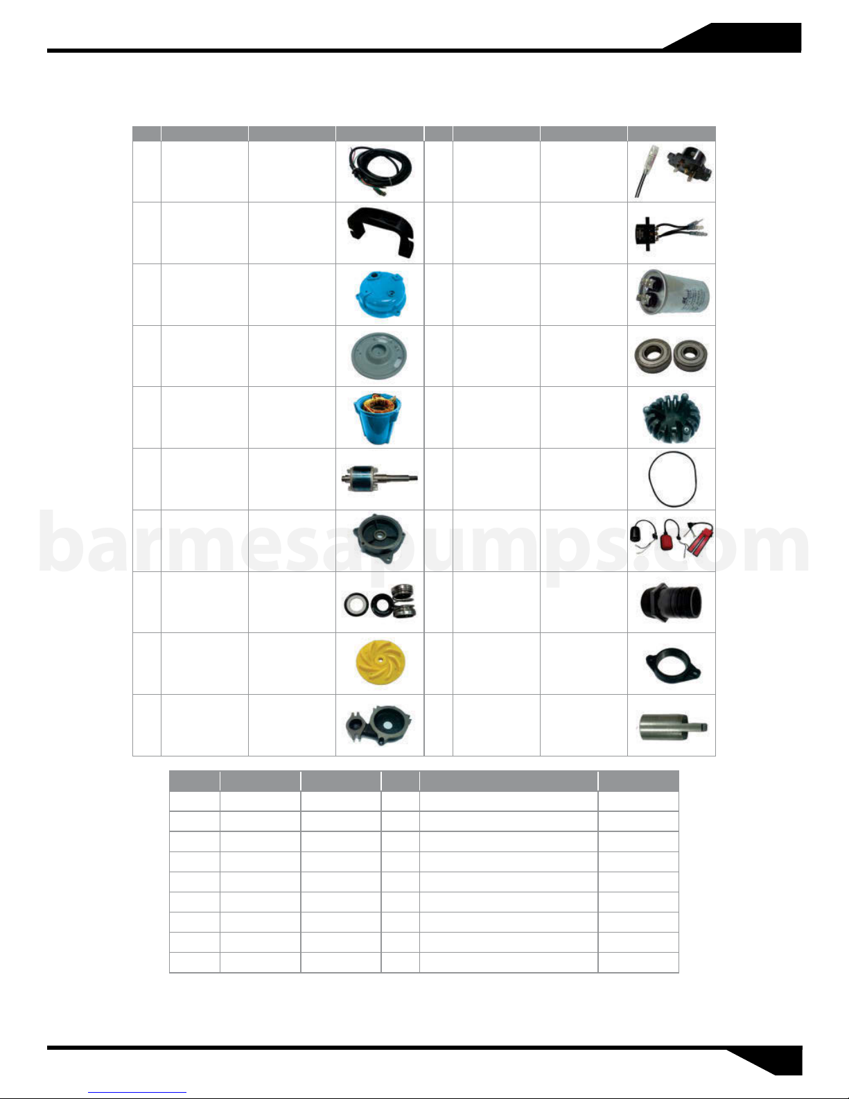
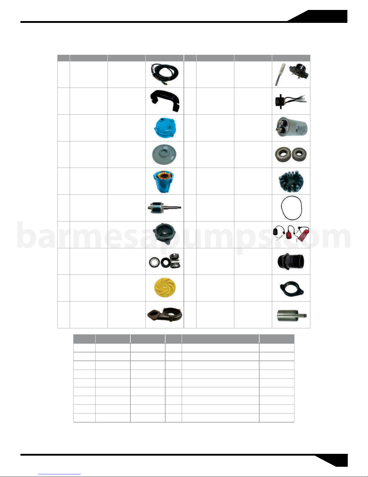
2AHS 0.5 HP
ITEM NAME MATERIAL PHOTO ITEM NAME MATERIAL PHOTO
Parts List
1 CABLE H07/UL 13
2 HANDLE NYLON 6 13
3
4 BRACKET SECC 15 BEARING
5
6
7 OIL CHAMBER CAST IRON 21
MOTOR
COVER
MOTOR HOUSING
+ STATOR
SHAFT WITH
ROTOR
ADC12 14 CAPACITOR
ADC12 16 STRAINER PVC
SUS410 17 O-RING NBR
PROTECTOR
(1 PHASE)
(OPTIONAL)
PROTECTOR
(3 PHASE)
FLOAT SWITCH
(OPTIONAL)
barmesapumps.com
MECHANICAL
8
11 IMPELLER HYTREL 27 FLANGE FC-15
12 PUMP CASING CAST IRON 28 AGITATOR SMF5030
SEAL
UPPER: CA/CE
LOWER: SIC/SIC
25
PLASTIC
HOSETAIL
ITEM NAME MATERIAL ITEM NAME MATERIAL
18 GASKET NBR 19-6 SCREW SUS 304
18-1 GASKET NBR 19-7 SCREW SUS 304
18-2 GASKET NBR 20 WASHER SUS 304
19 SCREW SUS 304 22 SCREW WITH O-RING
19-1 SCREW SUS 304 23 CABLE SEAT
19-2 SCREW SUS 304 24 EARTH LINE AND SCREW
19-3 SCREW SUS 304 26 "T" ADAPTER (OPTIONAL)
19-4 SCREW STEEL 29 INSULATING PAPER
19-5 SCREW SUS 304 34 CORRUGATED SPRING STEEL
For repair part please supply: Model Number and Serial as shown on Name Plate, and Part Description and Part Number as shown
on Parts List.
07
Page 9
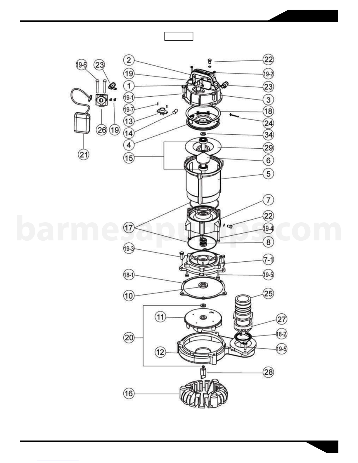
2AHS 1 HP
Repair Parts
Figure 6
barmesapumps.com
For repair part please supply: Model Number and Serial as shown on Name Plate, and Part Description and Part Number as shown
on Parts List.
08
Page 10
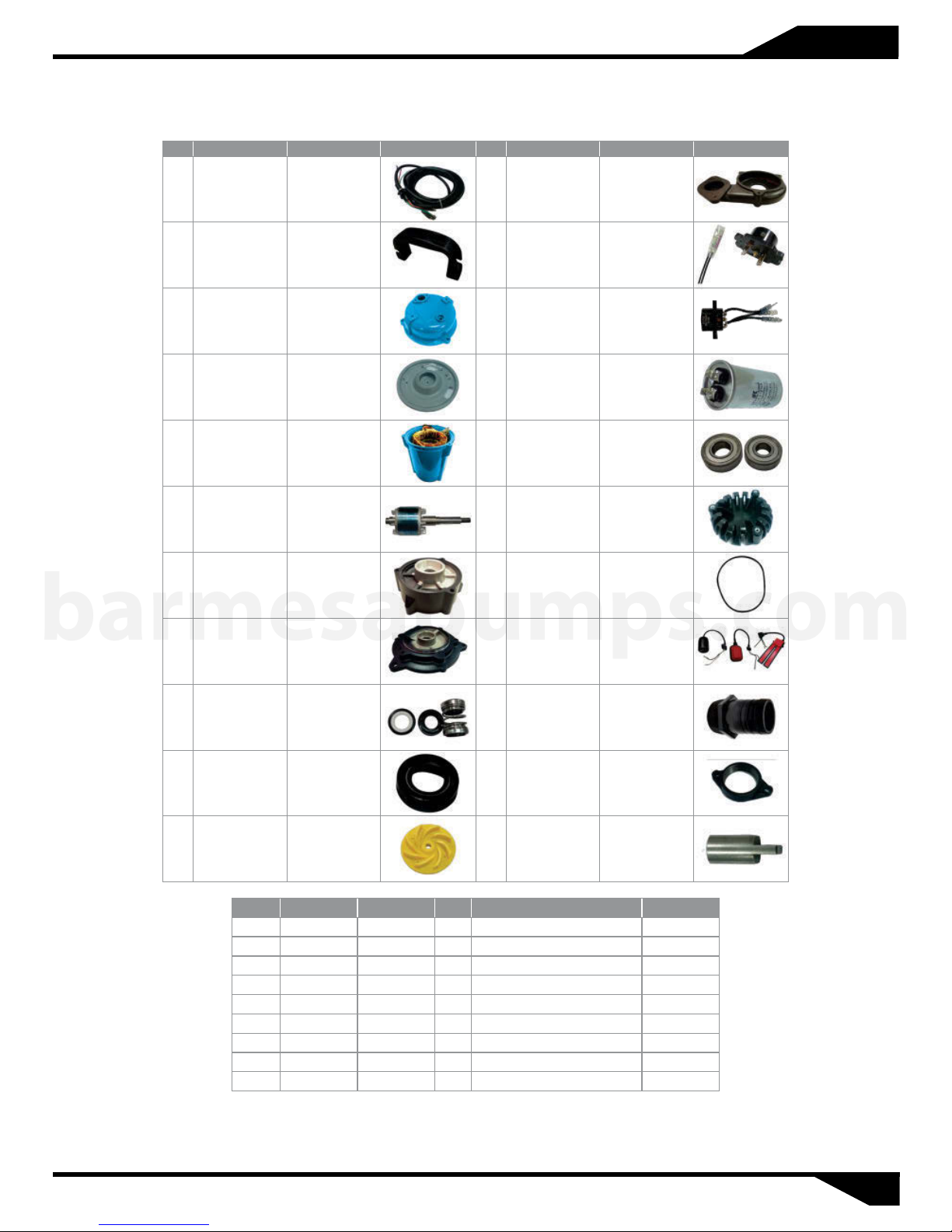
2AHS 1 HP
Parts List
ITEM NAME MATERIAL PHOTO ITEM NAME MATERIAL PHOTO
1 CABLE H07/UL 13
2 HANDLE NYLON 6 13
3
4 BRACKET SECC 15 BEARING
5
6
7 OIL CHAMBER CAST IRON 21
MOTOR
COVER
MOTOR HOUSING
+ STATOR
SHAFT WITH
ROTOR
ADC12 14 CAPACITOR
ADC12 16 STRAINER PVC
SUS410 17 O-RING NBR
PROTECTOR
(1 PHASE)
(OPTIONAL)
PROTECTOR
(3 PHASE)
FLOAT SWITCH
(OPTIONAL)
barmesapumps.com
MECHANICAL
8
11 IMPELLER HYTREL 27 FLANGE FC-15
12 PUMP CASING CAST IRON 28 AGITATOR SMF5030
SEAL
UPPER: CA/CE
LOWER: SIC/SIC
25
PLASTIC
HOSETAIL
ITEM NAME MATERIAL ITEM NAME MATERIAL
18 GASKET NBR 19-6 SCREW SUS 304
18-1 GASKET NBR 19-7 SCREW SUS 304
18-2 GASKET NBR 20 WASHER SUS 304
19 SCREW SUS 304 22 SCREW WITH O-RING
19-1 SCREW SUS 304 23 CABLE SEAT
19-2 SCREW SUS 304 24 EARTH LINE AND SCREW
19-3 SCREW SUS 304 26 "T" ADAPTER (OPTIONAL)
19-4 SCREW STEEL 29 INSULATING PAPER
19-5 SCREW SUS 304 34 CORRUGATED SPRING STEEL
For repair part please supply: Model Number and Serial as shown on Name Plate, and Part Description and Part Number as shown
on Parts List.
09
Page 11
2AHS 2 HP
Repair Parts
Figure 7
barmesapumps.com
For repair part please supply: Model Number and Serial as shown on Name Plate, and Part Description and Part Number as shown
on Parts List.
10
Page 12
2AHS 2 HP
Parts List
ITEM NAME MATERIAL PHOTO ITEM NAME MATERIAL PHOTO
1 CABLE H07/UL 12 PUMP CASING CAST IRON
2 HANDLE NYLON 6 13
3 MOTOR COVER ADC12 13
4 BRACKET SECC 14 CAPACITOR
MOTOR HOUSING
5
+ STATOR
SHAFT WITH
6
7 OIL CHAMBER A A356 17 O-RING NBR
ROTOR
ADC12 15 BEARING
SUS410 16 STRAINER PVC
barmesapumps.com
7-1 OIL CHAMBER B A356 21
PROTECTOR
(1 PHASE)
(OPTIONAL)
PROTECTOR
(3 PHASE)
FLOAT SWITCH
(OPTIONAL)
MECHANICAL
8
10 OIL SEAL NBR 27 FLANGE FC-15
11 IMPELLER HYTREL 28 AGITATOR SMF5030
SEAL
ITEM NAME MATERIAL ITEM NAME MATERIAL
18 GASKET NBR 19-6 SCREW SUS 304
18-1 GASKET NBR 19-7 SCREW SUS 304
18-2 GASKET NBR 20 WASHER SUS 304
19 SCREW SUS 304 22 SCREW WITH O-RING
19-1 SCREW SUS 304 23 CABLE SEAT
19-2 SCREW SUS 304 24 EARTH LINE AND SCREW
19-3 SCREW SUS 304 26 "T" ADAPTER (OPTIONAL)
19-4 SCREW STEEL 29 INSULATING PAPER
19-5 SCREW SUS 304 34 CORRUGATED SPRING STEEL
UPPER: CA/CE
LOWER: SIC/SIC
25
PLASTIC
HOSETAIL
For repair part please supply: Model Number and Serial as shown on Name Plate, and Part Description and Part Number as shown
on Parts List.
11
Page 13
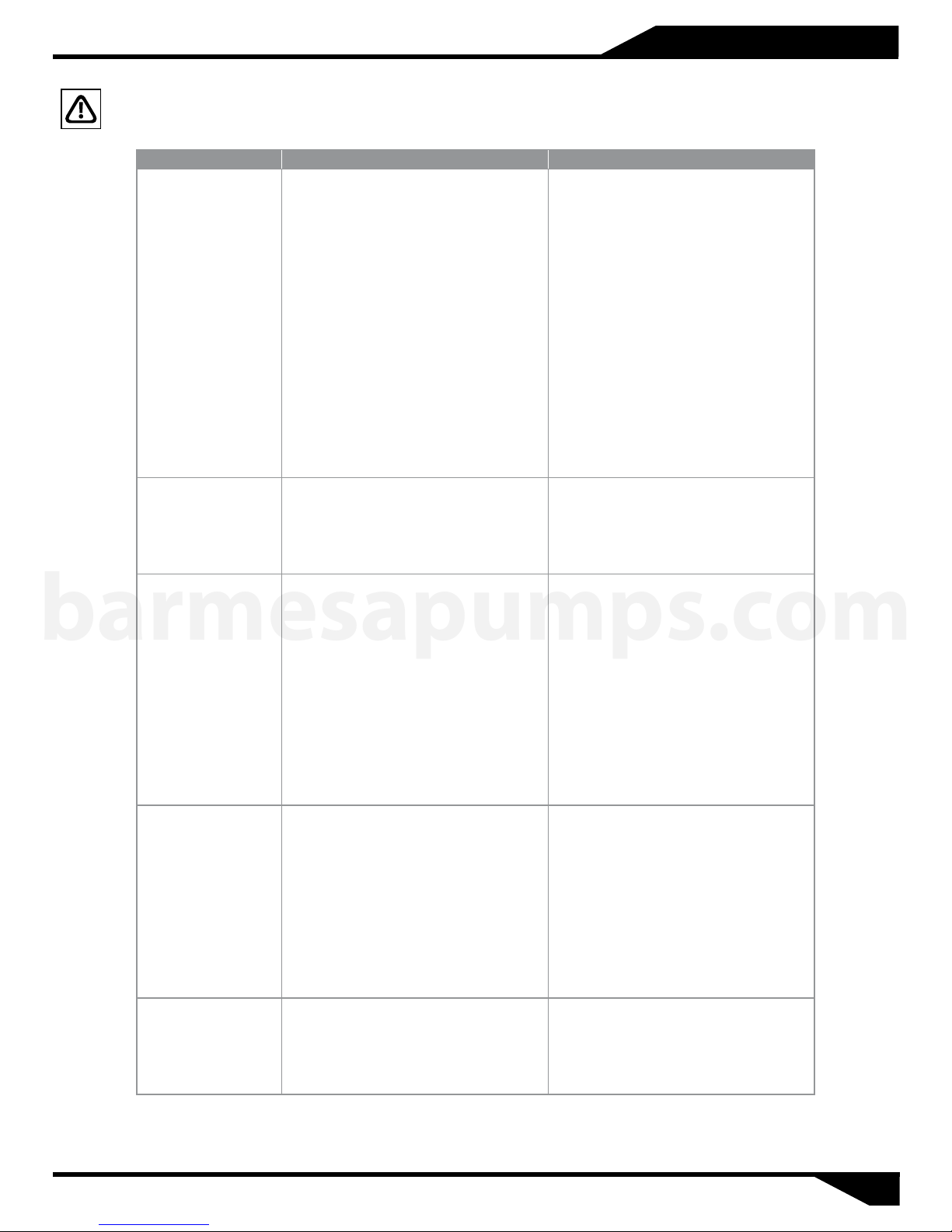
Troubleshooting Chart
Risk of electric shock. Always disconnect the pump from the power source before handling inspections or repairs.
Symptom Possible Cause(s) Corrective Action
(1) Power failure
(2) Large discrepancy between power
source and voltage
(3) Significant drop in voltage
(4) Motor phase malfunction
(5) Electric circuit connection faulty
(6) Faulty connection of control circuit
Does not start. Starts,
but imediately stops.
Operates, but stops
after a while.
barmesapumps.com
Does not pump.
Inadequate volume.
Over current.
Pump vibrates;
excessive operating
noise.
(7) Fuses is blown
(8) Faulty magnetic switch
(9) Water is not at level indicated by float
(10) Float is not in appropriate level
(11) Float is not effective
(12) Short circuit breaker is functioning
(13) Foreign matter clogging pump
(14) Motor burned out
(15) Motor bearing broken
(1) Prolonged dry operation has activated
motor protector and caused pump to stop
(2) High liquid temperature has activated
motor protector and caused pump to stop
(3) Reverse rotation
(1) Reverse rotation
(2) Significant drop in voltage
(3) Operating a 60 Hz pump with 50 Hz
(4) Discharge head is high
(5) Large piping loss
(6) Low operating water level causes air
suction
(7) Leaking from discharge piping
(8) Clogging of discharge piping
(9) Foreign matter in suction inlet
(10) Foreign matter clogging pump
(11) Worn impeller
(1) Unbalanced current and voltage
(2) Significant voltage drop
(3) Motor phase malfunction
(4) Operating 50 Hz pump on 60 Hz
(5) Reverse rotation
(6) Low head. Excessive volume of water
(7) Foreign matter clogging pump
(8) Motor bearing is worn out or damaged
(1) Reverse rotation
(2) Pump clogged with foreign matter
(3) Piping resonates
(4)Strainer is closed too far
(1)~(3) Contact electric power company
and devise counter-measures
(4) Inspect electric circuit
(5) Correct wiring
(6) Inspect connections and magnetic coil
(7) Check circuit then replace fuse
(8) Replace with correct one
(9) Raise water level
(10) Adjust the position of float
(11) Repair or replace
(12) Repair location of short circuit
(13) Remove foreign matter
(14) Repair or replace
(15) Repair or replace
(1) Raise water level to C.W.L.
(2) Lower liquid temperature
(3) Correct rotation
(1) Correct rotation (see Operation)
(2) Contact electric power company
(3) Check nameplate
(4) Recalculate and adjust
(5) Recalculate and adjust
(6) Raise water level or lower pump
(7) Inspect, repair
(8) Remove foreign matter
(9) Remove foreign matter
(10) Remove foreign matter
(11) Replace impeller
(1) Contact electric power company
(2) Contact electric power company and
devise counter-measure
(3) Inspect connections and magnetic
switch
(4) Check nameplate
(5) Correct rotation (see Operation 2)
(6) Replace pump with high head pump
(7) Remove foreign matter
(8) Replace bearing
(1) Correct rotation
(2) Disassemble and remove foreign
matter
(3) Improve piping
(4) Open strainer
NOTE: Barmesa Pumps assumes no responsibility for damage or injury due to disassembly in the field. Disassembly of the pumps or supplied accessories other
than at Barmesa Pumps or its authorized service centers, automatically voids warranty.
12
Page 14
Page 15

 Loading...