

Bargman N7000 User Manual [fr, en, es]
Guide d’installation
1. Effectuez le montage en mettant le bout du
couvercle (pincé le bout) en haut.
2. Montez le dispositif dans un endroit qui
n’est pas sujet à l’eau de pluie ou au
brouillard salin.
3. ATTENTION Dans l’état normal de
fonctionnement, l’interrupteur deviendra
chaud. ll faut choisir un employment de
montage permettant à la chaleur de se
dissiper.
4. ATTENTION Pour réduire le risque de
dommages accidentels causés par une surcharge de circuit, utilisez un disjoncteur
approprié au moment de relier le câblage à la
borne POSITIVE (+) de la batterie.
5. Le calibre de fil indiqué ci-dessous pour la
connexion de batterie est une exigence
minimale. Pour accroître la vitesse de charge
de la batterie secondaire, augmenter
le calibre du fil.
6. Le boîtier de l’interrupteur à 3 bornes assure
le retour de masse. Cette caractéristique
permet ne pas utiliser de fil de retour à la
masse dans le cas d’un montage effectué
sur un châssis d’automobile.
7. Le boîtier de l’interrupteur quadripôle est
doté d’isolant. On l’utilise habituellement
pour un montage sur des matériaux non
conducteurs: fibre de verre, bois, etc.
Cependant, l’interrupteur doit ici être monté
sur une plaque métallique de 6 po x 6 po ( 15
cm x 15 cm) pour empêcher la surchauffe.
8. Pour assistance technique et informations
concenant la garantie, prière de composer le:
1-888-785-5832 ou www.tekonsha.com
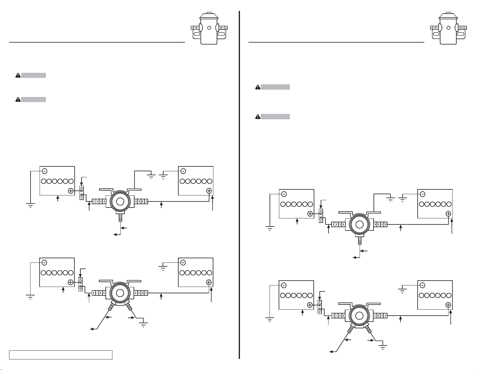
Directives pour l’interrupteur à 3 bornes, no de pièce 7000
et l’interrupteur à 4 bornes, no de pièce 7001
Directives D'Installation
3 Terminal Switch P/N 7000
4 Terminal Switch P/N 7001
Installation Instructions
P/N: 871 REV E 06/03
CHÂSSIS
D’AUTOMOBILE
CHÂSSIS
D’AUTOMOBILE
CHÂSSIS
D’ AUTOMOBILE
CHÂSSIS
D’AUTOMOBILE
BATTERIE
SECONDAIRE
BATTERIE
SECONDAIRE
FIL DE
10 GA
FIL DE
10 GA
FIL DE
16 GA
FIL DE
10 GA
FIL DE
10 GA
FIL DE
16 GA
BATTERIE
PRIMAIRE
BATTERIE
PRIMAIRE
CHÂSSIS D’AUTOMOBILE
SECONDARY BATTERY
10 GA
WIRE
16 GA
WIRE
10 GA
WIRE
TO 12 VOLT ACCESSORY SOURCE
ACTIVATED BY THE IGNITION SWITCH
PRIMARY
BATTERY
AUTO
CHASSIS
AUTO CHASSIS
SECONDARY BATTERY
10 GA
WIRE
10 GA
WIRE
16 GA
WIRE
AUTO CHASSIS
AUTO CHASSIS
PRIMARY
BATTERY
AUTO
CHASSIS
3 Terminal Switch Model P/N 7000
Modèle d’interrupteur à 3 bornes, no de pièce 7000
Modèle d’interrupteur à 4 bornes, no de pièce 7001
4 Terminal Switch Model P/N 7001
À LA SOURCE ACCESSOIRE DE 12 VOLTS
ACTIVÉE PAR LE COMMUTATEUR D’IGNITION
À LA SOURCE ACCESSOIRE DE 12 VOLTS
ACTIVÉE PAR LE COMMUTATEUR D’IGNITION
TO 12 VOLT ACCESSORY SOURCE
ACTIVATED BY THE IGNITION SWITCH
Installation Guide
1. Mount with cap end (crimped end) up.
2. Mount unit in an area that is not subjected
to water, rain or salt spray.
3. CAUTION Under normal operating
conditions the switch will become hot.
Mounting location should be selected to
allow for the heat to dissipate.
4. CAUTION To minimize the possibility of
accidental damage due to circuit overload,
use an appropriate circuit breaker inline when
wiring to the POSITIVE (+) terminal of the
battery.
5. The wire size indicated below for battery
connection is a minimum requirement. To
improve the secondary battery charge rate,
increase this wire size.
6. The three terminal switch housing provides
the ground return. This eliminates the need
for a ground return wire when mounted on
the auto chassis
7. The four terminal switch has an isolated case.
This would be used when mounting on a
non-conductive material, fiberglass, wood,
etc. However, to keep switch from
overheating it should be mounted on a
6” X 6” metal plate.
8.
For Technical Assistance and Warranty
Information call: 1-888-785-5832 or
www.tekonsha.com
30A AUTO-RESET
CIRCUIT BREAKER
(NOT SUPPLIED)
30A AUTO-RESET
CIRCUIT BREAKER
(NOT SUPPLIED)
DISJONCTEUR À
RÉENCLENCHEME
NT AUTOMATIQUE
30A (NON FOURNI)
DISJONCTEUR À
RÉENCLENCHEME
NT AUTOMATIQUE
30A (NON FOURNI)
Guía de instalación
1. Monte el extremo de la tapa
(extremo plegado) hacia arriba.
2. Monte la unidad en un lugar que no esté
sujeto a agua de la lluvia o rociado de sal.
3. ATENCIÓN Bajo condiciones normales de
operación, el interruptor se celentará.
La unbicatición del interruptor en el momento de instalación se debe seleccionar de
manera que permita que el calor se disipe.
4. ATENCIÓN Para reducir la posibilidad de
daños accidentales debido a la sobrecarga del
circuito, use un interruptor de circuito en
línea apropiado cuando conecta el cable al
borde POSITIVO (+) de la batería.
5. El tamaño del alambre indicado a
continuación para la conexión de la batería
es el requerimiento mínimo. Para mejorar la
velocidad de carga de la batería secundaria,
aumente el tamaño del alambre.
6. El armazón del interruptor de tres terminales
incluye el retorno a tierra. Esto elimina la
necesidad de instalar un alambre de retorno
a tierra cuando se lo monta en el chasis
del automóvil.
7. El interruptor de cuatro terminales tiene una
caja aislada. Esto se unsaría al instalarse en
un material sin conducción: fibra de vidrio,
madera, etc. Sin embarago, para evitar que el
interruptor se sobrecalliente, se debe instalar
en una chapa metálica de 6”x 6”
(15 cm x 15 am).
8. Para obtener asistencia técnica e información
de la garantía llame al: 1-888-785-5832 o
www.tekonsha.com
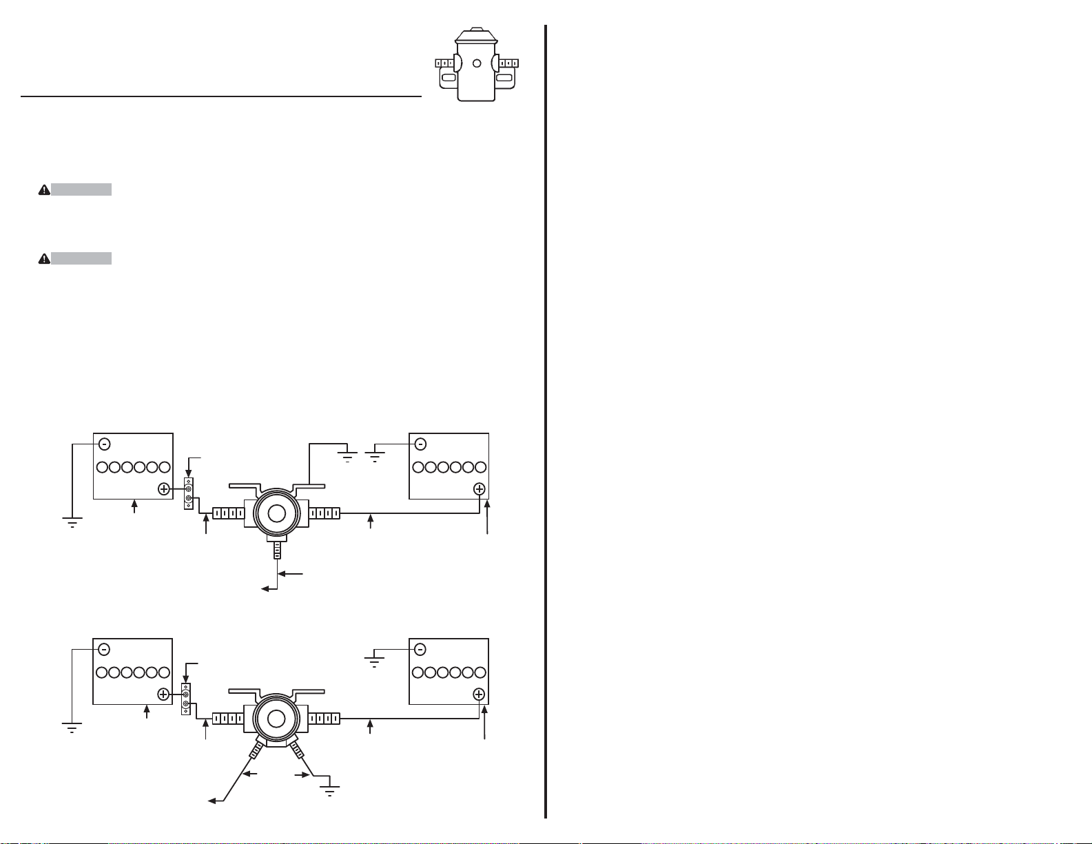
Instrucciones Interruptor de 3 bornes N/P 7000
Interruptor de 4 bornes N/P 7001
Instrucciones De Instalación
CHASIS DEL
AUTOMÓVIL
CHASIS DEL
AUTOMÓVIL
CHASIS DEL
AUTOMÓVIL
CHASIS DEL
AUTOMÓVIL
BATERÍA
PRIMARIA
BATERÍA
PRIMARIA
ALAMBRE
CALIBRE 10
ALAMBRE
CALIBRE 16
ALAMBRE
CALIBRE 10
ALAMBRE
CALIBRE 10
ALAMBRE
CALIBRE 10
ALAMBRE
CALIBRE 16
BATERÍA SECUNDARIA
BATERÍA SECUNDARIA
CHASIS DEL AUTOMÓVIL
HACIA LA FUENTE ACCESORIA DE 12 VOLTIOS
ACTIVADA POR EL INTERRUPTOR DE IGNICIÓN
Interruptor de 3 bornes N/P 7000
Interruptor de 4 bornes N/P 7001
HACIA LA FUENTE ACCESORIA DE
12 VOLTIOS ACTIVADA POR EL
INTERRUPTOR DE IGNICIÓN
DISYUNTOR DE CIRCUITOS PARA AUTOREINICIALIZACIÓN 30A
(NO INCLUIDO)
DISYUNTOR DE CIRCUITOS PARA AUTOREINICIALIZACIÓN 30A
(NO INCLUIDO)
 Loading...