

Page 1
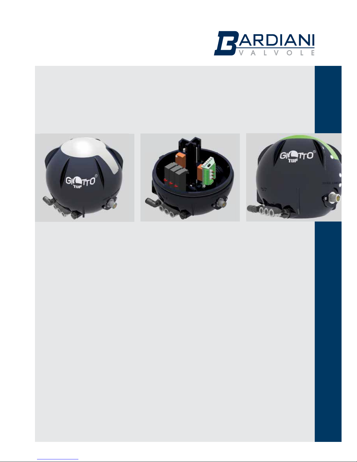
Instruction, Use and Maintenance Manual
CONTROL UNITS
Bardiani Valvole S.p.A.
via G. di Vittorio, 50/52 - 43045 Fornovo di Taro (PR) - Italy
tel. +39 0525 - Fax 0525 3408
[email protected] - www.bardiani.com
GB-IST-GIOT360-0816
GIOTTO TOP
®
Page 2

Instruction, Use and Maintenance Manual
GB-IST-GIOT360-0816
MANUAL REVISION DAT E
2
Page 3

Instruction, Use and Maintenance Manual
GB-IST-GIOT360-0816
INDEX
1 Safety,Warning and Mandatory Signs 5
2 General safety warnings 6
3 Technical Data 7
4 Giotto Top
®
Installation 8
5 Giotto Top
®
Pneumatic connections 10
6 Giotto Top
®
Electrical connections 13
7 Giotto Top
®
Control unit 16
8 Giotto Top
®
Assembly / Disassembly 17
9 Troubleshooting 21
10 Maintenance and Cleaning 22
11 Ce Certificate 23
12 Warranty 24
13 Recommendations 25
3
Page 4

Instruction, Use and Maintenance Manual
GB-IST-GIOT360-0816
INTRODUCTION
This “Instruction, Use and Maintenance Manual” has been drawn up expressly for expert
technical personnel. Consequently any information which can easily be deducted from reading
the text and/or examining the illustrations and/or drawings provided herein shall not be the
object of further explanation.
It forms an integral part of the Products supplied and must be read prior to any installation,
operation and/or maintenance of all types of valves provided.
This manual must be saved for future reference and be kept readily available at the unit.
With regards to the use of valves compliant with EU Directive 2014/34/UE (ATEX), consultation
of a specic manual is mandatory.
The essential characteristics of all types of valves described herein being consistent, the
Manufacturer reserves the right to alter and or complement and or update at any time and with
no obligation to notify so in writing, the data and or information relevant to the use of the valves
described in this "Instruction, Use and Maintenance Manual".
A constantly updated version of this "Instruction, Use and Maintenance Manual" is available
at the Manufacturer's website www.bardianivalvole.it.
Under no circumstance shall the Manufacturer be held liable for consequences resulting
from failure and or improper use of the instructions contained in this Manual and relating to
the installation, operating, maintenance and storage of the products.
All rights reserved.
Full or part reproduction, transfer and or recording of any part of this "Instruction, Use and
Maintenance Manual" by all means, whether it be electronic, on hard copy, mechanical or any
other means or recording or reuse is strictly prohibited without the prior written consent of the
Manufacturer and for any use other than that of the Buyer.
(Translation of the Original Instructions in the italian Language)
4
Page 5
Instruction, Use and Maintenance Manual
GB-IST-GIOT360-0816
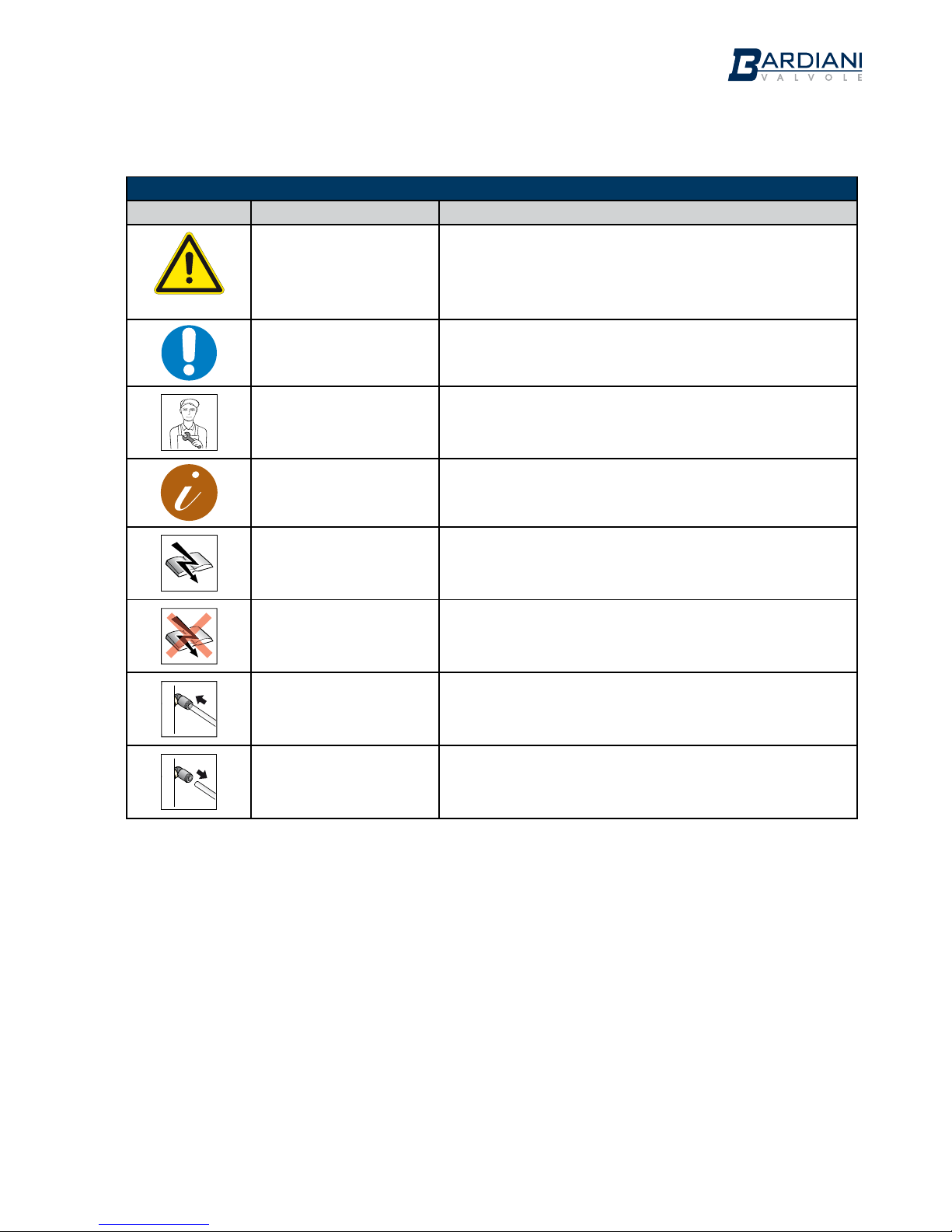
1 Safety,Warning and Mandatory Signs
SIGNALS
Pictogram Description Notes
WARNING!
General
This tells the person in question that the operation
described involves (when not performed in accordance
with the relative safety regulations) the risk of personal
injury.
OBLIGATION
General
Special instructions must be followed to avoid injury to
persons.
PERSONAL
PERSONNEL
Dismantling/Assembling and maintenance operations
must be carried out by expert technicians only.
NOTE
Follow the indicated note with care
ELECTRICAL
CONNECTION
Electrical connection to the control unit
ELECTRICAL
DISCONNECTION
Electrical disconnection from the control unit
PNEUMATIC
CONNECTION
Compressed air connection to the control unit
PNEUMATIC
DISCONNECTION
Compressed air disconnection from the control unit
5
Page 6
Instruction, Use and Maintenance Manual
GB-IST-GIOT360-0816
2 General safety warnings
The control unit has been designed to control the pneumatically controlled process valves manufactured
by Bardiani Valvole S.p.A.. It is possible to fit the Giotto Top® with a maximum of three solenoid valves
for controlling the process valve and up to a maximum of four inductive sensors, including an external
one for controlling the position.
For the electrical connections inside the control unit, there are three different configurations:
• LED terminal block: the LEDs indicate, in the presence of the relative inductive sensor, the status of
the valve: green light = valve open; yellow light = valve closed; white light = bottom or top lift activated.
• AS-i card: the LEDs indicate the status of the corresponding solenoid valve.
• 10-pole terminal block: no LEDs.
General warnings
• Always read the technical data carefully before machine installation, operation and maintenance.
• The Giotto Top
®
must always be installed, operated and maintained by authorized personnel. Said
personnel must know and understand both the unit and the contents of the manual.
• Take care over any separate parts of the Giotto Top® when removing it from its packaging.
• Always connect the air supply carefully and disconnect it after use.
• Always connect the power supply carefully and disconnect it after use.
• Never touch the moving parts in the Giotto Top® or valves.
• Always handle detergents with care.
Prohibited use
Use of the control unit is not envisaged:
• for any operations other than those for which it was designed.
WARNING
The machine may not he used inside premises where there is a potentially explosive atmosphere or risk
of fire unless otherwise stated by the manufacturer (in the case of valves certified in accordance with
Directive 2014/34/EU please refer to the ATEX Manual).
WARNING
The control unit contains circuits classified as LOW VOLTAGE LIMITED ENERGY CIRCUIT. For correct use
in North America dimension the protection circuits in accordance with Standard UL508A.
WARNING
ALWAYS make sure the electrical and pneumatic connections are NOT active when executing operations
on the Giotto Top® and that the power supply voltage is only 24 Vdc.
BARDIANI VALVOLE S.p.A. declines all liability for
installation, use or maintenance which fails to comply with
the indications provided in this manual!
6
Page 7
Instruction, Use and Maintenance Manual
GB-IST-GIOT360-0816
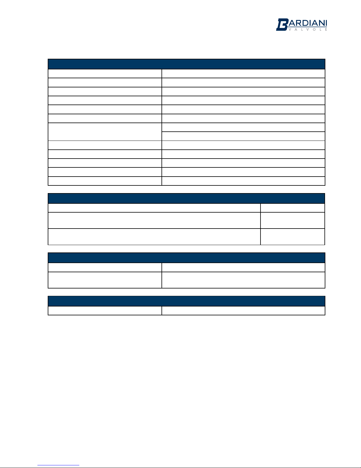
3 Technical Data
CONTROL UNIT TECHNICAL DATA
Weight from 0.55 Kg to 0.65 Kg depending on the configuration
Casing material PA66 + PA6-GF30 (glass fibre reinforced nylon)
Gaskets material NBR
Protection class IP67
Air supply and vent connections 1/8” BSP
Air line connections 6 mm / 1/4” (ON REQUEST)
Electrical connections 7-pole connector or M12 5- or 8-pole connector
Threaded fitting for cable gland PG11 or M20x1.5
Field bus connections Actuator Sensor interface (AS-i).
Vibrations 1mm amplitude f=10..55Hz
Storage temperature -25..+70°C
Operating temperature -10...+50°C
Air supply Class 2,4,3 according to ISO 8573-1
SOLENOID VALVE APPLICATION CRITERIA
Single Acting Valves 1 Solenoid valve
Double Acting Valves (1 normally open and 1 normally closed), Mixproof and
Twin-Stop valves (2 normally closed)
2 Solenoid valves
Mixproof valves with air supply for opening, top and bottom lift (3 normally
closed)
3 Solenoid valves
SOLENOID VALVE TECHNICAL DATA
Electrical power supply 24 Vdc
Air pressure supply max. 7bar
min. 6bar
INDUCTIVE SENSOR TECHNICAL DATA
Electrical power supply 24 Vdc
In the event of any doubt, please contact Bardiani Valvole S.p.A.
7
Page 8
Instruction, Use and Maintenance Manual
GB-IST-GIOT360-0816
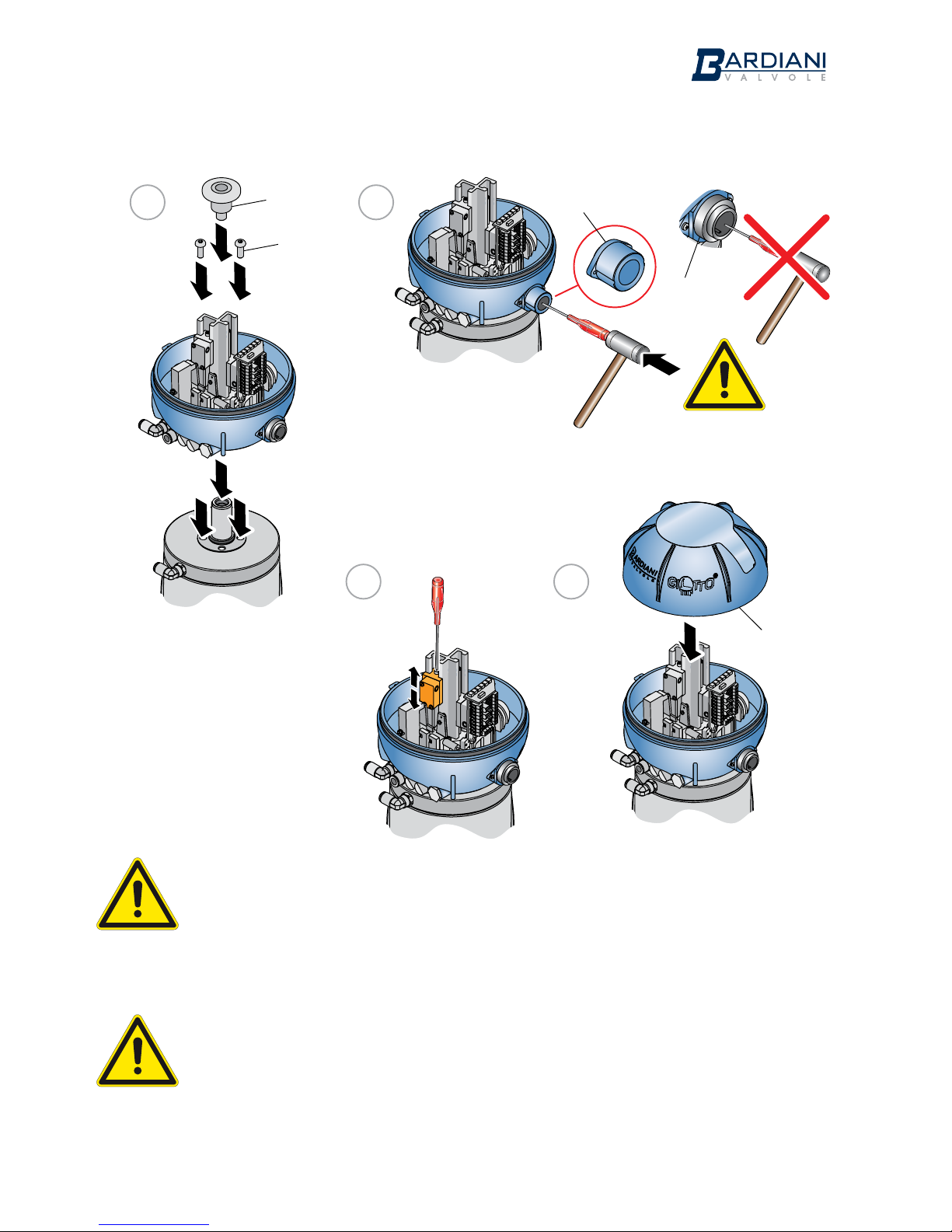
4 Giotto Top® Installation
WARNING
Always make sure that all wires are connected and securely fastened to the terminals and that the
solenoid valves, solenoid valves support, AS-i card and LED terminal block (when present) and any other
parts inside the Giotto Top ® are well assembled and secured.
WARNING
Always make sure that the electrical and pneumatic connections are disconnected when carrying out
operations on the Giotto Top®.
8
114b
114c
114d
25
22
1 2
3
26
4
114a
Page 9
Instruction, Use and Maintenance Manual
GB-IST-GIOT360-0816
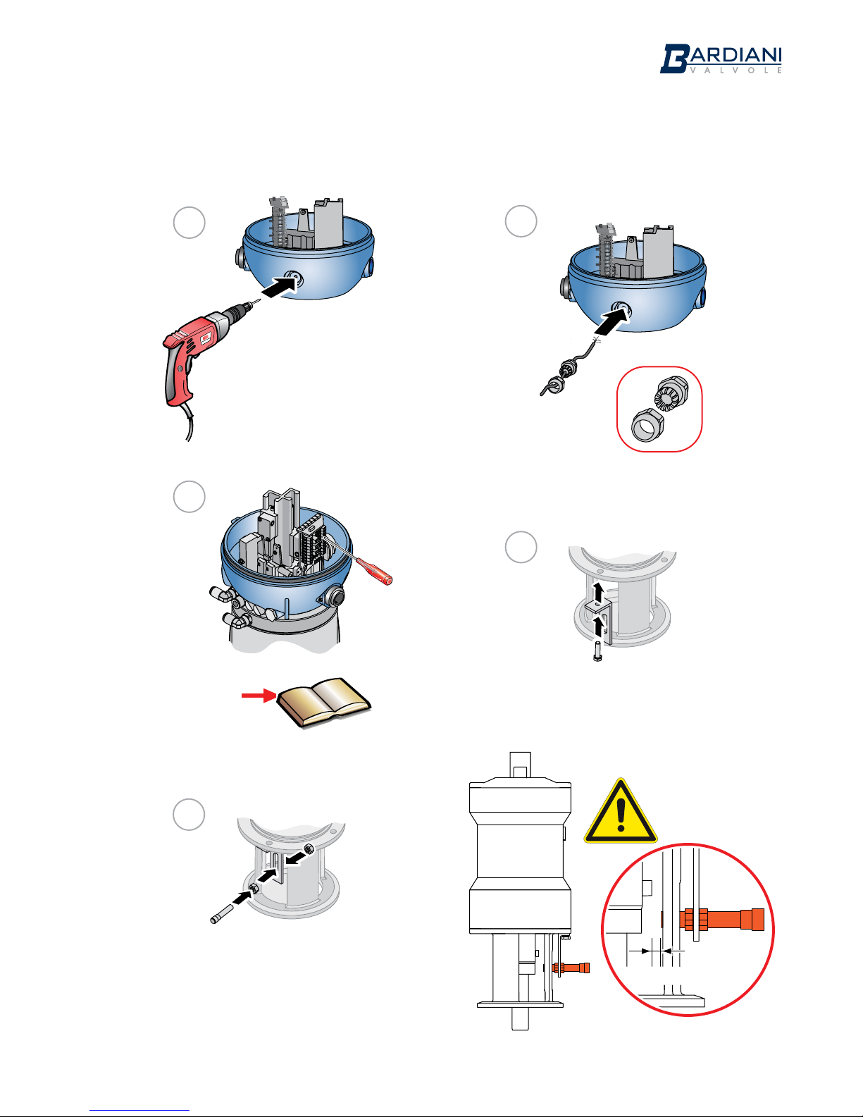
External inductive sensor installation
Pages 13-16
9
1
2
3
4
Ø 1,5 мм
Ø 12,5 мм
PG7
(M12x1,5)
5
Page 10
Instruction, Use and Maintenance Manual
GB-IST-GIOT360-0816
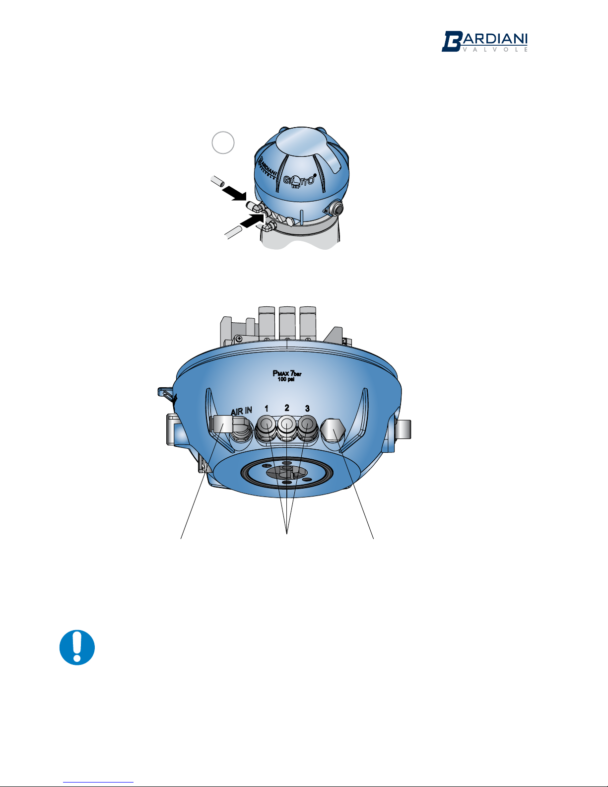
5 Giotto Top® Pneumatic connections
Compressed Air
inlet 1/8”
(BSP)
Connections
for air tting
1/8”
Air vent 1/8”
(BSP)
WARNING
Use only pipes with an external diameter of 6 mm.
Cut these pipes with a suitable cutter to avoid damaging the pipe which could lead to Giotto Top®
malfunctions.
Select a suitable length of pipe which allows the Giotto Top® to be removed without unscrewing the
anchoring.
10
6
Page 11
Instruction, Use and Maintenance Manual
GB-IST-GIOT360-0816
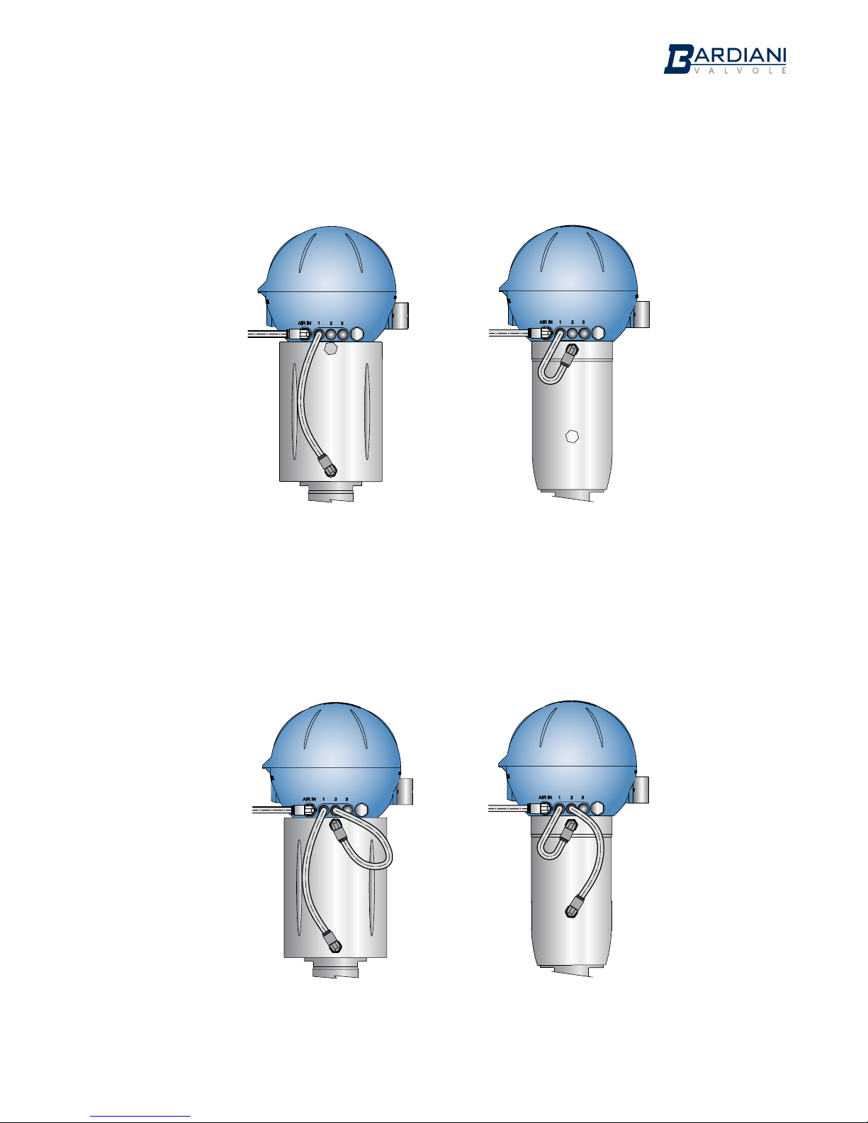
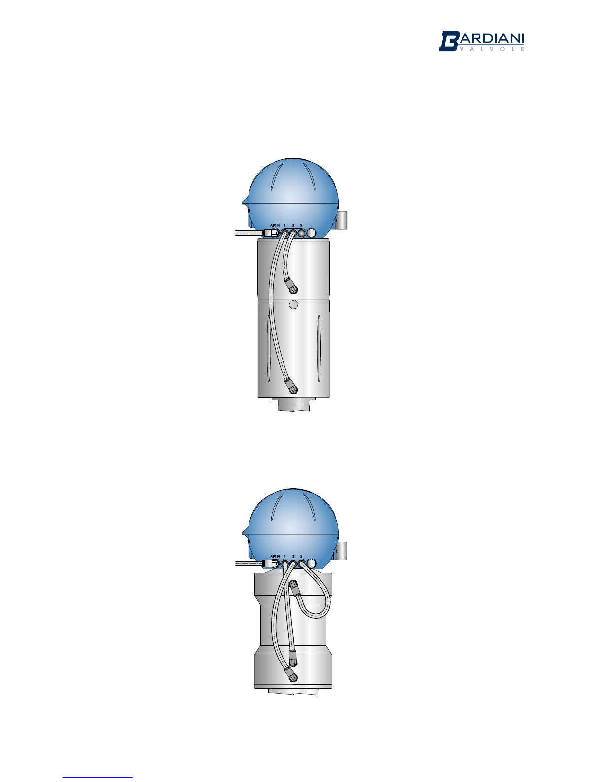
Valve with single acting actuator
Valve with double acting actuator
11
Page 12
Instruction, Use and Maintenance Manual
GB-IST-GIOT360-0816
Valve with single acting actuator with Twin Stop
Mixproof valve
12
Page 13
Instruction, Use and Maintenance Manual
GB-IST-GIOT360-0816
6 Giotto Top® Electrical connections
Solenoid valve 3
Solenoid valve 1
N.C.
Solenoid valve 1
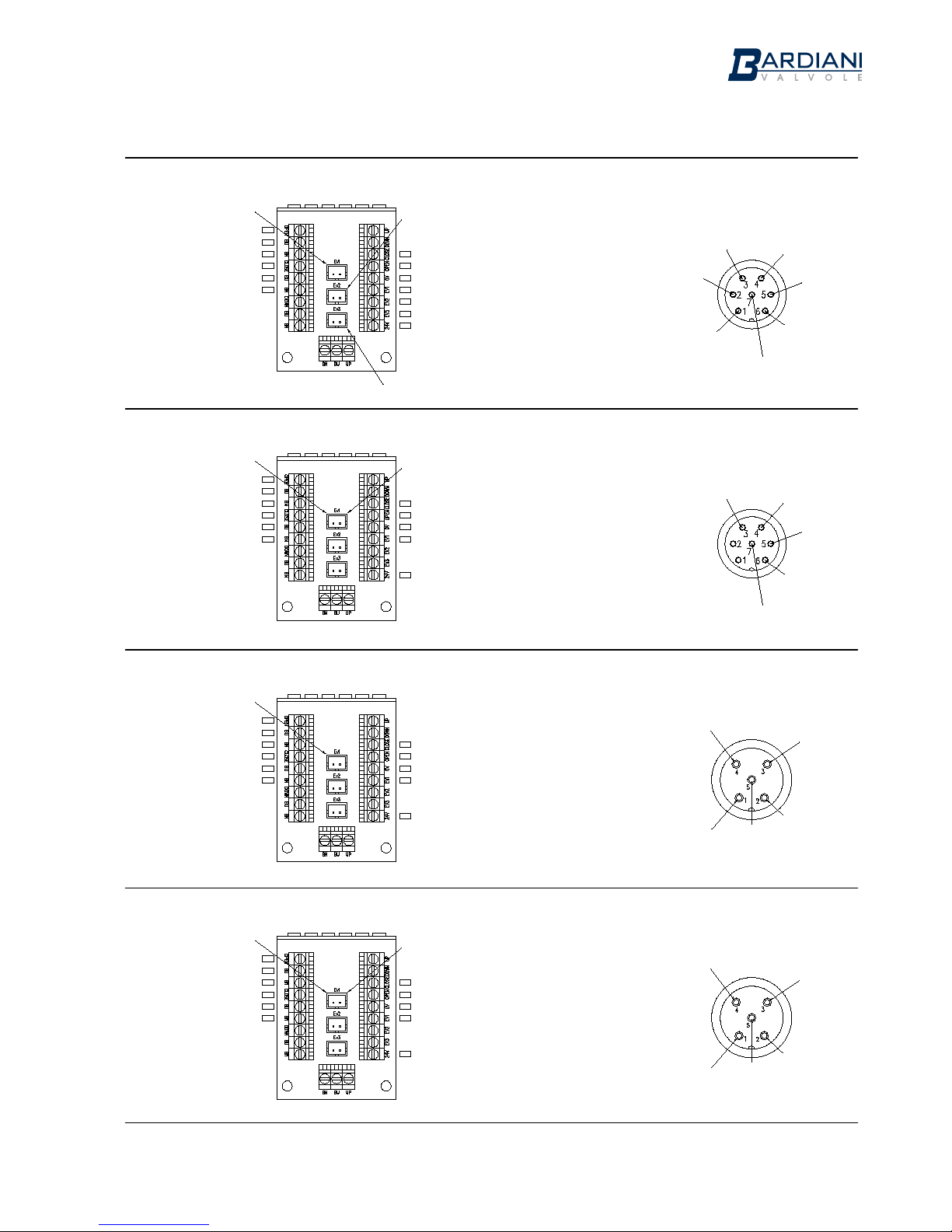
1,2 PNP sensors with 1,2,3 normally closed solenoid valves and 7-pole connector
Sensor
VALVE
OPEN
Sensor
VALVE
CLOSED
Signal (Black)
0Vdc (Blue)
+24Vdc (Brown)
Signal (Black)
0Vdc (Blue)
+24Vdc (Brown)
Sensor
VALVE
OPEN
Sensor
VALVE
CLOSED
Signal (Black)
0Vdc (Blue)
+24Vdc (Brown)
Signal (Black)
0Vdc (Blue)
+24Vdc (Brown)
PIN
Connector
(7)
(6)
(4)
(3)
(2)
(1)
(5)
COLOR
Wire
(White)
(Blue)
(Brown)
(Purple)
(Black)
(Red)
(Gray)
Sensor signal
VALVE CLOSED
+24Vdc
Solenoid valves
0Vdc
PIN
Connector
(1)
(2)
(7)
(6)
(4)
(3)
(5)
COLOR
Wire
(Red)
(Black)
(Blue)
(White)
(Brown)
(Purple)
(Gray)
CLOSED VALVE Sensor signal
OPEN VALVE Sensor signal
0Vdc
+24Vdc Solenoid valves
+24Vdc Sensors
Solenoid valve 2
N.O.
Solenoid valve 2
CLOSED VALVE Sensor signal
OPEN VALVE Sensor signal
0Vdc
+24Vdc Solenoid valve 1
+24Vdc Solenoid valve 2
+24Vdc Solenoid valve 3
+24Vdc Sensors
Solenoid valve 3
+24Vdc
Solenoid valve 1
0Vdc
+24Vdc
Solenoid valve 2
+24Vdc
Solenoid valve 3
Sensor signal
VALVE OPEN
+24Vdc
Sensors
Sensor signal
VALVE CLOSED
Sensor signal
VALVE OPEN
+24Vdc
Sensors
1,2 PNP sensors with 1 normally closed solenoid valves and 5-pole connector
Sensor
VALVE
OPEN
Sensor
VALVE
CLOSED
Solenoid valve
Signal (Black)
0Vdc (Blue)
+24Vdc (Brown)
Signal (Black)
0Vdc (Blue)
+24Vdc (Brown)
+24Vdc
Solenoid valve
0Vdc
Sensor signal
VALVE CLOSED
Sensor signal
VALVE OPEN
+24Vdc
Sensors
PIN
Connector
(2)
(4)
(3)
(5)
(1)
COLOR
Wire
(White)
(Black)
(Blue)
(Gray)
(Brown)
Sensor
VALVE
OPEN
Sensor
VALVE
CLOSED
Signal (Black)
0Vdc (Blue)
+24Vdc (Brown)
Signal (Black)
0Vdc (Blue)
+24Vdc (Brown)
+24Vdc
Solenoid valves
0Vdc
Sensor signal
VALVE CLOSED
Sensor signal
VALVE OPEN
PIN
Connector
(2)
(4)
(3)
(5)
(1)
COLOR
Wire
(White)
(Black)
(Blue)
(Gray)
(Brown)
+24Vdc
Sensors
CLOSED VALVE Sensor signal
OPEN VALVE Sensor signal
0Vdc
+24Vdc Solenoid valve
+24Vdc Sensors
Solenoid valve 1
N.C.
Solenoid valve 2
N.O.
CLOSED VALVE Sensor signal
OPEN VALVE Sensor signal
0Vdc
+24Vdc Solenoid valves
+24Vdc Sensors
1,2 PNP sensors with 2 solenoid valves (1 N.C. and 1 N.O.) for double acting 7-pole connector
1,2 PNP sensors with 2 solenoid valves (1 N.C. and 1 N.O.) for double acting 5-pole connector
13
Page 14
Instruction, Use and Maintenance Manual
GB-IST-GIOT360-0816
Solenoid valve 1
Solenoid valve 1
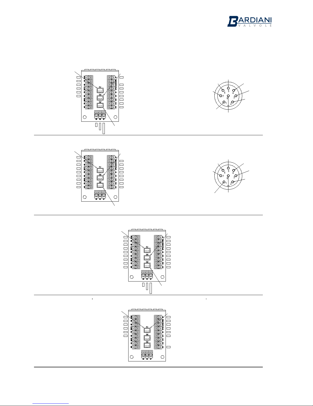
1,2,3 PNP sensors with 1,2,3 normally closed solenoid valves and 8-pole connector
1,2,3 PNP sensors with 1,2,3 normally closed solenoid valves and 8-pole connector
Sensor
VALVE
OPEN
Sensor
VALVE
CLOSED
Signal (Black)
0Vdc (Blue)
+24Vdc (Brown)
Signal (Black)
0Vdc (Blue)
+24Vdc (Brown)
Sensor
VALVE
OPEN
Sensor
VALVE
CLOSED
Signal (Black)
0Vdc (Blue)
+24Vdc (Brown)
Signal (Black)
0Vdc (Blue)
+24Vdc (Brown)
Signal (Black)
0Vdc (Blue)
+24Vdc (Brown)
PIN
Connector
(8)
(1)
(6)
(7)
(5)
(3)
(4)
(2)
COLOR
Wire
(Red)
(White)
(Pink)
(Blue)
(Gray)
(Green)
(Yellow)
(Brown)
External Sensor signal
UPPER LIFT
PIN
Connector
(8)
(1)
(6)
(7)
(5)
(3)
(4)
(2)
COLOR
Wire
(Red)
(White)
(Pink)
(Blue)
(Gray)
(Green)
(Yellow)
(Brown)
LOWER LIFT Sensor signal
CLOSED VALVE Sensor signal
OPEN VALVE Sensor signal
0Vdc
+24Vdc Solenoid valve 1
+24Vdc Solenoid valve 2
+24Vdc Solenoid valve 3
+24Vdc Sensors
Solenoid valve 2
Solenoid valve 2
UPPER LIFT Sensor signal
CLOSED VALVE Sensor signal
OPEN VALVE Sensor signal
0Vdc
+24Vdc Solenoid valve 1
+24Vdc Solenoid valve 2
+24Vdc Solenoid valve 3
+24Vdc Sensors
Solenoid valve 3
+24Vdc
Solenoid valve 1
0Vdc
Sensor signal
VALVE OPEN
+24Vdc
Solenoid valve 3
+24Vdc
Sensors
Sensor signal
VALVE CLOSED
Sensor signal
VALVE OPEN
+24Vdc
Sensors
1,2,3,4 PNP sensors with 1,2,3 normally closed solenoid valves
Sensor
VALVE
OPEN
Sensor
VALVE
CLOSED
Solenoid valve 1
Signal (Black)
0Vdc (Blue)
+24Vdc (Brown)
Signal (Black)
0Vdc (Blue)
+24Vdc (Brown)
Signal (Black)
0Vdc (Blue)
+24Vdc (Brown)
1,2 PNP sensors with 2 solenoid valves (1 N.C. and 1 N.O.) for double acting
signal (black)
Sensor
UPPER LIFT
(external)
+24Vdc (brown)
0Vdc (Blue)
+24Vdc
Solenoid valve 2
Sensor signal
VALVE CLOSED
+24Vdc
Solenoid valve 1
Sensor
LOWER LIFT
+24Vdc
Solenoid valve 2
+24Vdc
Solenoid valve 3
Sensor signal
LOWER LIFT
Solenoid valve 3
signal (black)
Sensor
UPPER LIFT
(external)
+24Vdc (brown)
0Vdc (Blue)
Sensor
LOWER LIFT
Solenoid valve 2
Solenoid valve 3
UPPER LIFT Sensor signal
LOWER LIFT Sensor signal
CLOSED VALVE Sensor signal
OPEN VALVE Sensor signal
0Vdc
+24Vdc Solenoid valve 1
+24Vdc Solenoid valve 2
+24Vdc Solenoid valve 3
+24Vdc Sensors
Sensor
VALVE
OPEN
Sensor
VALVE
CLOSED
Solenoid valve 1
Signal (Black)
0Vdc (Blue)
+24Vdc (Brown)
Signal (Black)
0Vdc (Blue)
+24Vdc (Brown)
Solenoid valve 2
UPPER LIFT Sensor signal
LOWER LIFT Sensor signal
CLOSED VALVE Sensor signal
OPEN VALVE Sensor signal
0Vdc
+24Vdc Solenoid valves
+24Vdc Sensors
0Vdc
14
Page 15
Instruction, Use and Maintenance Manual
GB-IST-GIOT360-0816
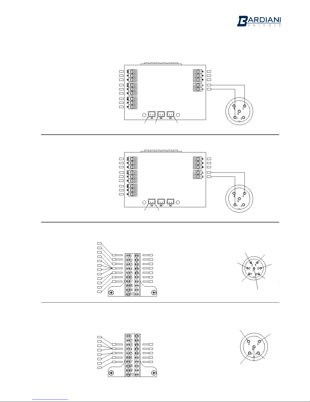
AS-i 360° Board 1,2,3,4 PNP sensors with 1,2,3 normally closed solenoid valves
Sensor
VALVE
OPEN (DI0)
Sensor
VALVE
CLOSED (DI1)
Sensor
LOWER LIFT
(DI3)
Signal (Black)
0Vdc (Blue)
+24Vdc (Brown)
Signal (Black)
0Vdc (Blue)
+24Vdc (Brown)
Signal (Black)
0Vdc (Blue)
+24Vdc (Brown)
Solenoid valve 1
(DO0)
Solenoid valve 2
(DO1)
Solenoid valve 3
(DO2)
AS-i Network
Signal (Black)
0Vdc (Blue)
+24Vdc (Brown)
AS-i - (Blue)
AS-i + (Brown)
Sensor
UPPER
LIFT (DI2)
AS-i 360° Board 1,2 PNP sensors with 2 solenoid valves (1 N.C. and 1
N.O.) for double acting
Sensor
VALVE
OPEN (DI0)
Sensor
VALVE
CLOSED (DI1)
Sensor
LOWER LIFT
(DI3)
Signal (Black)
0Vdc (Blue)
+24Vdc (Brown)
Signal (Black)
0Vdc (Blue)
+24Vdc (Brown)
Signal (Black)
0Vdc (Blue)
+24Vdc (Brown)
Solenoid valve 1
(DO0)
Solenoid valve 2
(DO1)
AS-i Network
Signal (Black)
0Vdc (Blue)
+24Vdc (Brown)
AS-i - (Blue)
AS-i + (Brown)
Sensor
UPPER
LIFT (DI2)
1,2,3 normally closed solenoid valves and 7-pole connector
+24Vdc Solenoid valve 3
+24Vdc Solenoid valve 2
+24Vdc Solenoid valve 1
0Vdc
+24Vdc Sensors
HIGH Sensor signal
LOW Sensor signal
PIN
Connector
(1)
(2)
(3)
(4)
(5)
(6)
(7)
COLOR
Wire
(Red)
(Black)
(Purple)
(Brown)
(Gray)
(White)
(Blue)
Sensor signal
LOW
+24Vdc
Sensors
+24Vdc
Solenoid valve 1
+24Vdc
Solenoid valve 2
+24Vdc
Solenoid valve 3
Sensor signal
HIGH
0Vdc
+24Vdc Solenoid valve 3 (Red)
+24Vdc Solenoid valve 2 (Red)
+24Vdc Solenoid valve 1 (Red)
0Vdc Solenoid valve 3 (Black)
0Vdc Solenoid valve 2 (Black)
0Vdc Solenoid valve 1 (Black)
0Vdc Sensor HIGH (Blue)
0Vdc Sensor LOW (Blue)
+24Vdc Sensor HIGH (Brown)
+24Vdc Sensor LOW (Brown)
HIGH Sensor signal (Black)
LOW Sensor signal (Black)
+24Vdc
Sensors
+24Vdc Solenoid valve
0Vdc
+24Vdc Sensors
HIGH Sensor signal
LOW Sensor signal
PIN
Connector
(5)
(3)
(1)
(4)
(2)
COLOR
Wire
(Gray)
(Blue)
(Brown)
(Black)
(White)
1,2,3 normally closed solenoid valves and 5-pole connector
Sensor signal
LOW
Sensor signal
HIGH
0Vdc
+24Vdc
Solenoid valve
+24Vdc Solenoid valve (Red)
0Vdc Solenoid valve (Black)
0Vdc Sensor HIGH (Blue)
0Vdc Sensor LOW (Blue)
+24Vdc Sensor HIGH (Brown)
+24Vdc Sensor LOW (Brown)
HIGH Sensor signal (Black)
LOW Sensor signal (Black)
15
Page 16
Instruction, Use and Maintenance Manual
GB-IST-GIOT360-0816
7 Giotto Top® Control unit
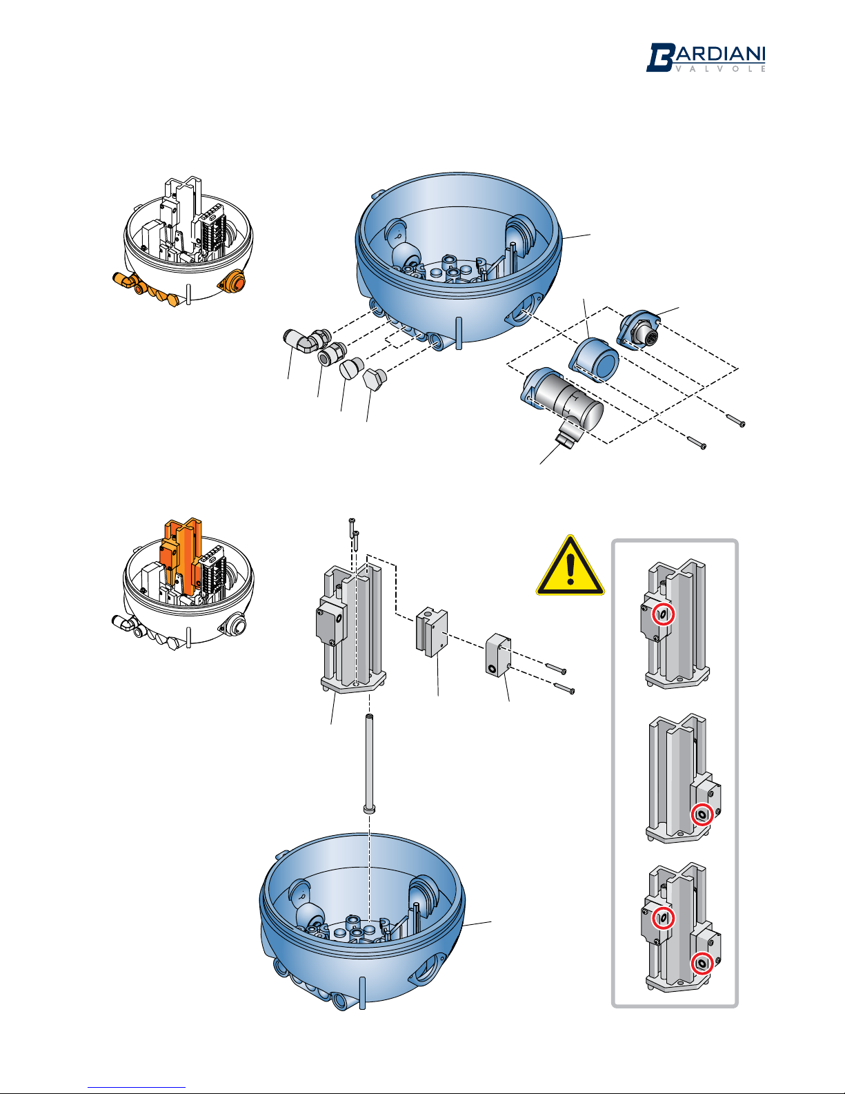
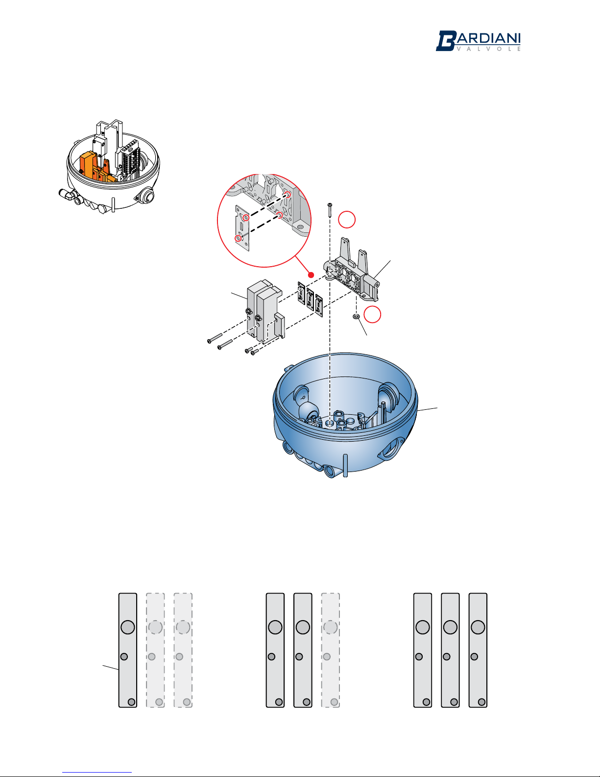
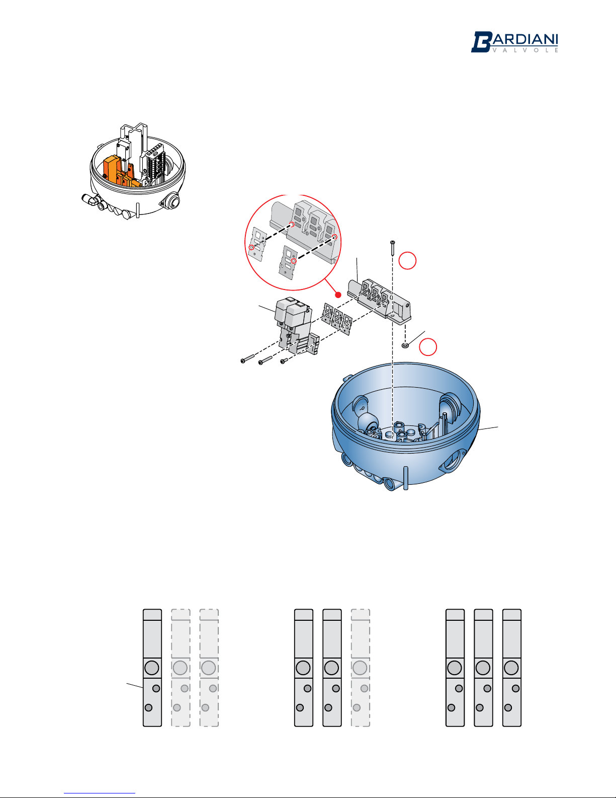
NO. DESCRIPTION
21 Base
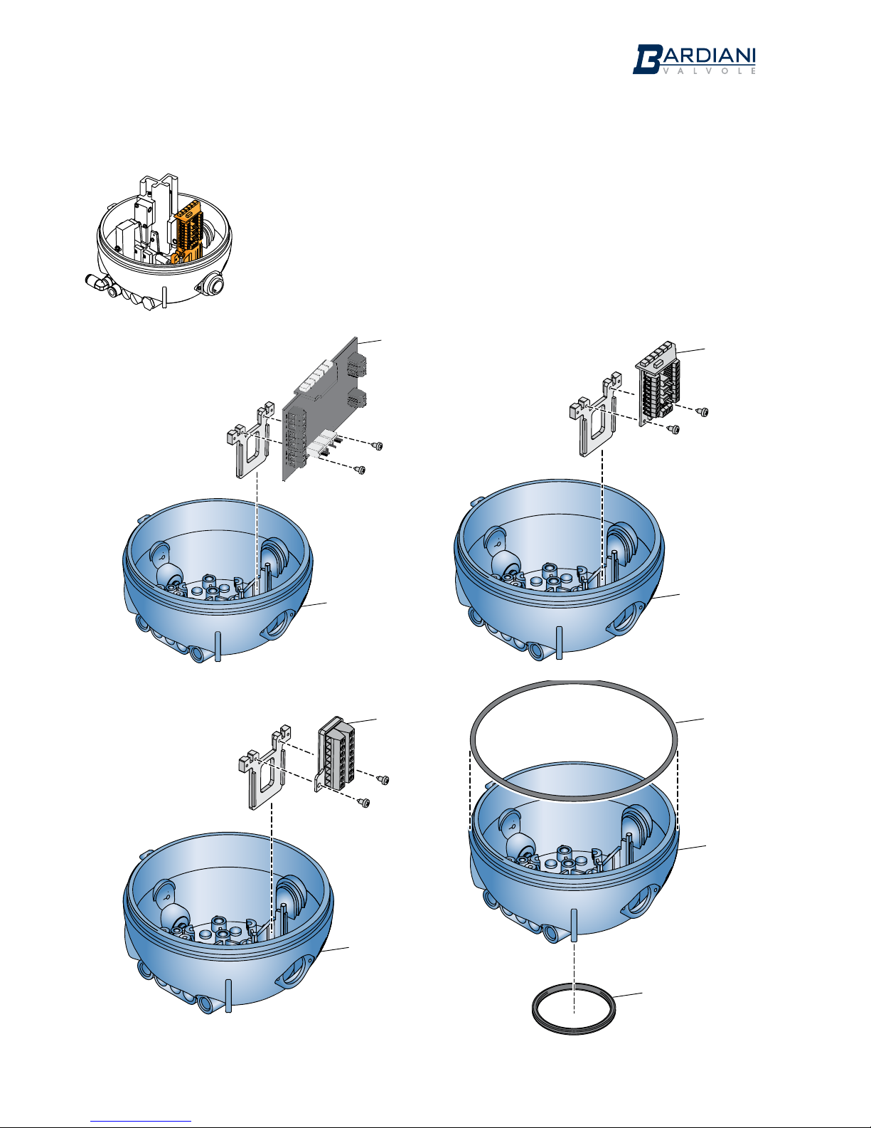
21a Sealing ring
21b Sealing ring
21d Double guide
21e Vent plug
21f Air coupling
21g Air coupling
21i Cap
21k Terminal block with support
22 Cam
25 Screw
26 Bardiani case
27a Sensor
27d Micro-size inductive sensors holder slide
114a Sleeve for cable gland
114b 7-pole connector
114c 5-pole connector
114d 8-pole connector
192 Solenoid valve
192b Solenoid valve support
192c Cap
192d Solenoid valve board
192e Sealing ring
283 AS-i board
16
Page 17
Instruction, Use and Maintenance Manual
GB-IST-GIOT360-0816
8 Giotto Top® Assembly / Disassembly
17
21d
27d
27a
21
21e
21i
21g
21f
114b
114a
114c
114d
21
Page 18
Instruction, Use and Maintenance Manual
GB-IST-GIOT360-0816
Solenoid valve sequence
NC NC NO NO NO NO
18
TYPE 8
NC NC NA NCNC NC
192
x 4
192
x 5
192b
192e
21
Page 19
Instruction, Use and Maintenance Manual
GB-IST-GIOT360-0816
Solenoid valve sequence
NC NC NO NC NC NC
19
TYPE 5
NC NC NA NCNC NC
192
x 2
x 5
192e
192b
192
21
Page 20
Instruction, Use and Maintenance Manual
GB-IST-GIOT360-0816
20
TYPE B - TYPE S
21k
21
21k
21
21k
21
21b
21a
21
Page 21
Instruction, Use and Maintenance Manual
GB-IST-GIOT360-0816
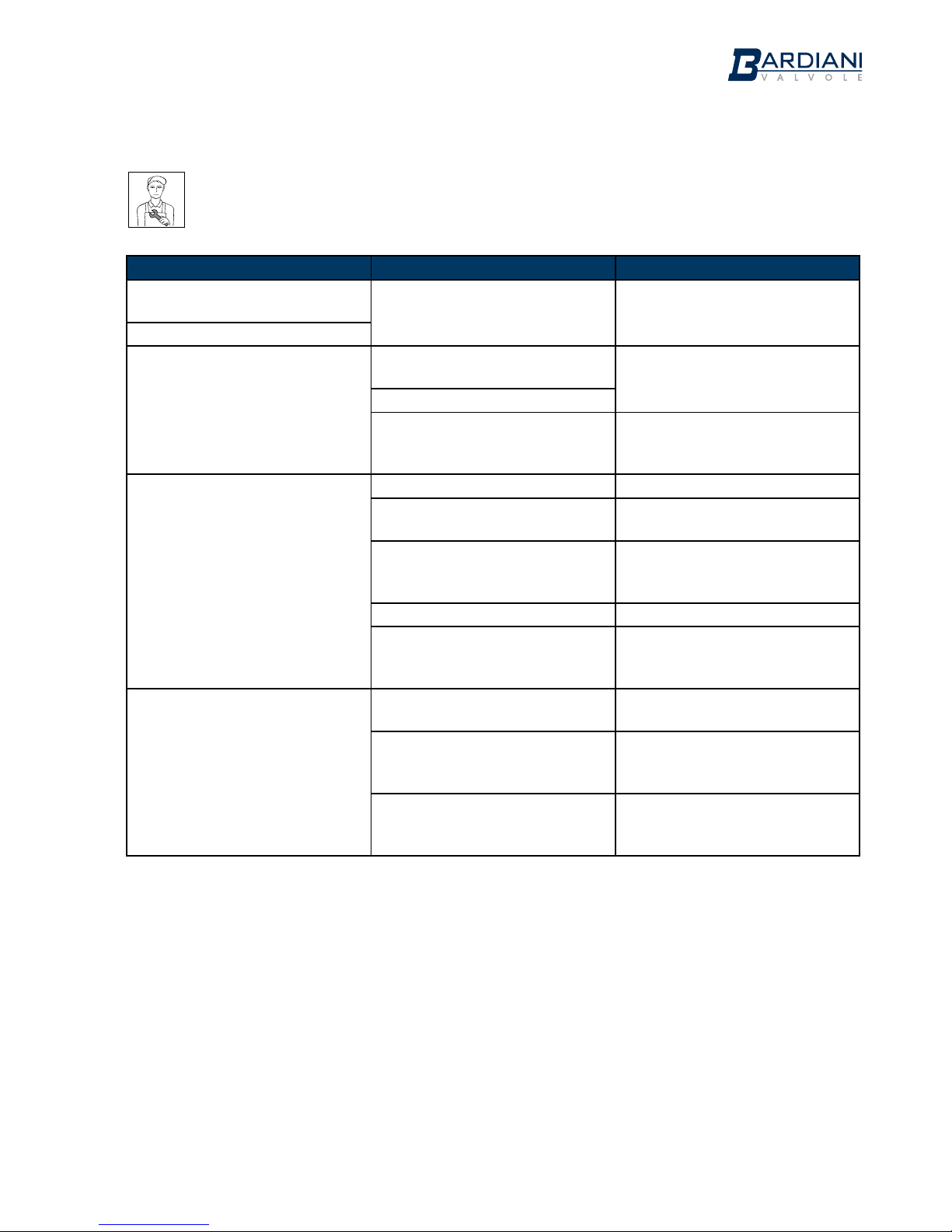
9 Troubleshooting
PROBLEM POSSIBLE CAUSE POSSIBLE SOLUTION
Air leak from solenoid valve
support
No gaskets or loose fitting
Check the sealing capacity of the
gaskets and tighten the screws
Air leaks in safety valve
The LED do not come on
Circuit board
damaged
Replace the circuit board
Damaged LEDs
Inductive sensors
not working
Check the sensor connections in
the terminal block and restore if
necessary
The solenoid valve does not
activate
Damaged solenoid valve Replace solenoid valve
Circuit board
damaged
Replace the circuit board
Air supply pressure
incorrect
Consult the Technical Data
section
in the Manual
Solenoid valve support damaged Replace solenoid valve support
Electrical connections not made
properly
Check the connections in the
terminal block on the electrical
board and tighten the screws.
The inductive sensors are not
working
Inductive sensors
damaged
Replace inductive sensors
Electrical connections not made
properly
Check the connections in the
terminal block on the electrical
board and tighten the screws.
Distance between the cam and
the inductive sensors greater
than 1.5 mm.
Check the centring of the Giotto
and the fastening to the double
guide
21
Page 22

Instruction, Use and Maintenance Manual
GB-IST-GIOT360-0816
10 Maintenance and Cleaning
When used correctly the Giotto Top® does not need any special maintenance.
Any repair work must be carried out by authorized personnel only, making sure that the electrical and
pneumatic power supplies have been disconnected before carrying out any operation inside the Giotto
Top®.
WARNING
Before using cleaning products make sure they are compatible with the materials used to construct the
Giotto Top®, both the casing and the gaskets.
If solvents or cleaning agents containing acids or alkaline substances are used, always make sure the
Giotto Top® is immediately rinsed with clean water.
When so doing, pay particular attention to those areas where there are orifices or openings.
WARNING
Each time the casing is open, make sure that the various cables inside it are repositioned where they do
not interfere with cam movement.
WARNING
Should it be necessary to replace any component of the Giotto Top®, contact Bardiani Valvole S.p.A.
to purchase the necessary spare part as the use of any products not supplied by us may compromise
correct valve operation or constitute a hazard for personnel.
22
Page 23
Instruction, Use and Maintenance Manual
GB-IST-GIOT360-0816
11 Ce Certi cate
BARDIANI VALVOLE S.p.A..
Via G. di Vittorio 50/52
43045 Fornovo di Taro (Pr)
GB - EC Declaration of
conformity - A3-P-PRG-GB
A3-P-PRG-GB Ed. 1. Rev. 0
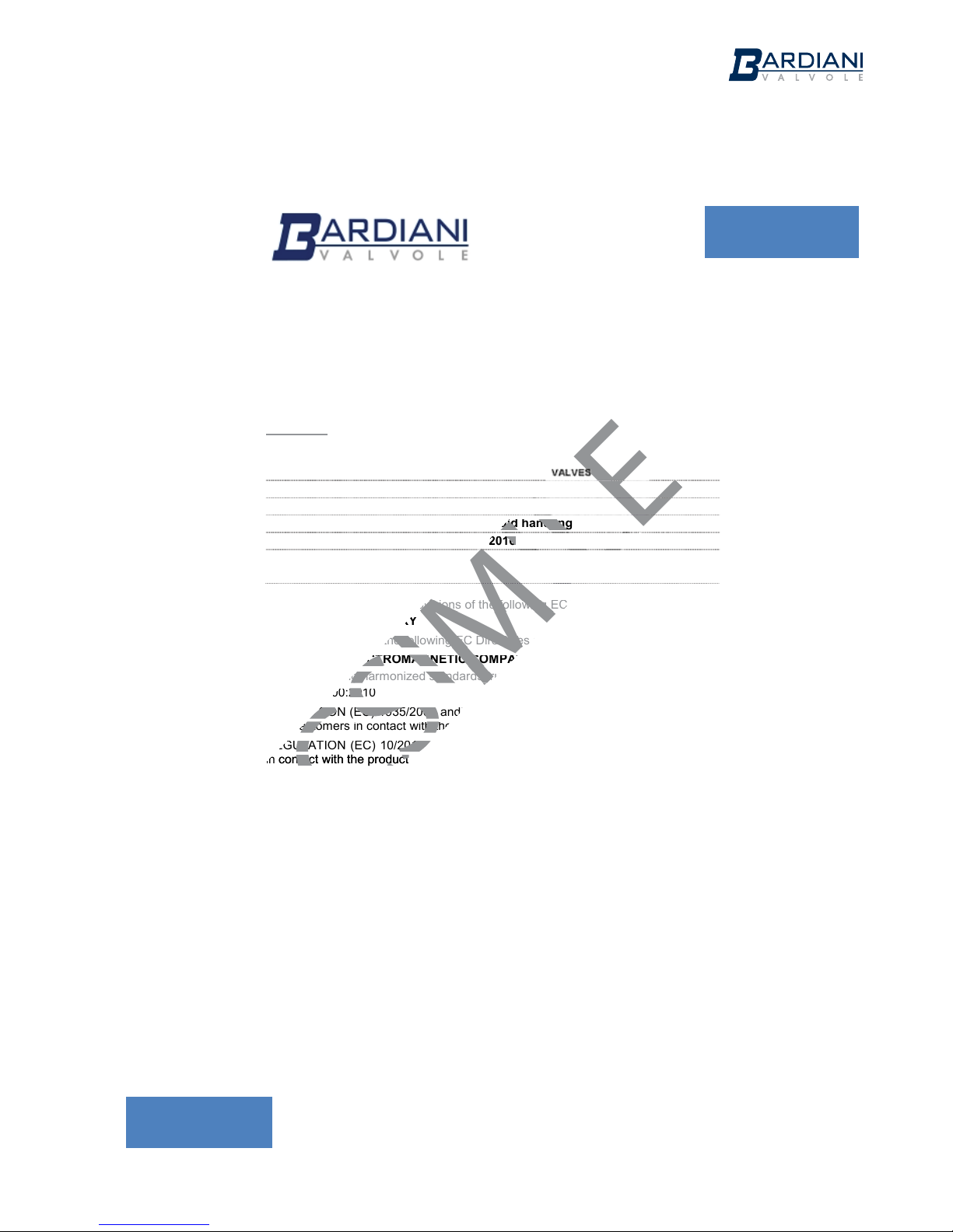
EC DECLARATION OF CONFORMITY
OF THE MACHINERY
(EC) 2006/42, Annex. II, p. 1 A
BARDIANI VALVOLE S.p.A.
Via G. di Vittorio 50/52 – 43045 Fornovo di Taro (Pr) – Italy
Declares
under its own responsibility that the machine:
Type:
P
P
NNEEUUMMAATTIIC
C
Model:
Serial number:
Function:
Fluid handling
Year of construction:
2016
Reference
complies with all relevant provisions of the following EC directives:
(EC) 2006/42 MACHINERY
and also comply with the following EC Directives and Regulations:
(EU) 2014/30 ELECTROMAGNETIC COMPATIBILITY DIRECTIVE (EMC)
and the following harmonized standards, rules and / or technical specifications applied:
EN ISO 12100:2010
REGULATION (EC) 1935/2004 and subsequent amendments and additions with regard to steel
and elastomers in contact with the product
REGULATION (EC) 10/2011 and subsequent amendments and additions with regard to PTFE
in contact with the product
Fornovo di Taro
10/10/2016 ______________________________
Emanuela Bardiani
Legal representative
2016
2016
ing EC directives:
ing EC directives:
in contact with the product
in contact with the product
23
Page 24

Instruction, Use and Maintenance Manual
GB-IST-GIOT360-0816
12 Warranty
1. VALIDITY
Bardiani Valvole‘s Products are manufactured in compliance with the technical specifications laid out in
their “Instruction, Use and Maintenance Manual” and are fully compliant with the directives specifically
mentioned in these manuals.
Bardiani Valvole S.p.A. guarantees its own Products against any design and/or construction and/or
material defects and/or faults for a period of 12 (twelve) months from the date of delivery.
Notification of any Product defects and/or faults must be sent in writing to Bardiani Valvole S.p.A. within
8 (eight) days from their detection, providing adequate documentation of the defect/fault encountered as
evidence.
Services provided in the warranty period shall not result in an extension of the warranty beyond the
stipulated 12 (twelve)-month period, as this warranty validity period is to be considered mandatory.
2. CONTENTS OF THE WARRANTY
Notwithstanding and without prejudice to the rights of the Buyer, which may be acknowledged by
applicable law, this warranty it to be intended as limited, at the discretion of Bardiani Valvole S.p.A., to
the repair and/or replacement of the Product and/or part of the Product and/or its components which
is/are found to be defective due to design and/or manufacturing and/or material faults.
In the event of repair and/or replacement of the Product and/or any one of its parts and/or components,
any returned item/s shall become the property of Bardiani Valvole S.p.A. and the relative shipping costs
shall charged to Bardiani Valvole S.p.A.
Bardiani Valvole S.p.A., shall be under no obligation to compensate for any immaterial and/or indirect
damages and shall in no way be held liable for consequential damages and/or losses, such as (by way
of example only), damages due to loss of business, contracts, opportunities, time, production, profits,
goodwill, image etc.
No retailer or distributor or dealer or agent or representative or employee or person appointed by
Bardiani Valvole S.p.A. is authorized to make any amendments and/or integrations and/or extensions to
this warranty.
3. WARRANTY EXCLUSIONS
- Elastomers and electrical components are expressly excluded from this warranty.
- This warranty does not cover design faults emerging whenever a Product is manufactured by Bardiani
Valvole S.p.A. based on designs and/or technical specifications provided by the Buyer.
- Moreover this warranty excludes the following:
- faults and/or defects resulting from incorrect and/or unsuitable and/or inadequate transportation of
the Product;
- faults and/or defects resulting from failure to comply with the indications laid out in the “Instruction,
Use and Maintenance Manual” with regards to installation of the Product or in any event caused by
incorrect and/or unsuitable and/or improper installation;
- faults and/or defects resulting from failure to comply with indications laid out in the “Instruction,
Use and Maintenance Manual” with regards to use and/or maintenance operations and/or storage
of the Product or in any event caused by incorrect and/or unsuitable and/or improper use and/or
maintenance operations and/or storage;
- faults and/or defects due to normal wear and tear of the Product and/or its parts and/or its components;
- faults and/or defects in the Product and/or its parts and/or its components for work and/or repairs
being carried out by unskilled staff or staff that has not been authorised by Bardiani Valvole S.p.A.;
- faults and/or defects in the Product and/or its parts and/or its components caused by its being dropped
and/or banged and/or dented and/or misused and/or tampering and/or breakage and/or accidents
and/or any other event caused by negligence and/or carelessness and/or neglect by the Buyer and in
general for any causes not ascribable to design and/or manufacturing and/or material defects;
- faults and/or defects in the Product and/or its parts and/or its components caused by other events
beyond the control of Bardiani Valvole S.p.A., such as force majeure or unforseeable circumstances.
24
Page 25

Instruction, Use and Maintenance Manual
GB-IST-GIOT360-0816
13 Recommendations
1.Consultation of the "Instruction, Use and Maintenance Manual” is mandatory prior to the installation,
use and maintenance of the products of all Products. All the information, indications, specifications,
technical details provided herein are based on test data which the Manufacturer Bardiani Valvole S.p.A.
holds to be reliable nevertheless the above is not deemed to be assumed as fully exhaustive inasmuch as
not every possible use has been envisaged.
2.All the illustrations and drawings provided are to be intended as indicative and therefore not binding,
the Products illustrations being for presentation purposes only.
3.It is the Buyer's duty to assess the suitability of the products for the use he intends to make of the
same prior to placing the order as he/she will take the risks and accept liability in case of incorrect choice
and use of the Products.
4.The Manufacturer strongly recommends the Buyer to contact their sales team and request any
information that might be needed in relation to the specifications and uses of the Products.
5.The information provided in this manual refers to the standard products manufactured by Bardiani
Valvole S.p.A. and therefore cannot be assumed to apply to customized products as well.
6.Bardiani Valvole S.p.A. reserves the right to amend and/or integrate and/or update the data and/
or information and/or technical details relative to Products at any time and without prior notice. Please
visit the website www.bardiani.com, where the latest updated of the "Instruction, Use and Maintenance
Manual" can be found".
7.The content and validity of the warranty covering the Products of Bardiani Valvole S.p.A are dealt with
in the relevant section in the “Instruction, Use and Maintenance Manual” which constitutes an integral
part of the Products themselves.
8.Bardiani Valvole S.p.A., shall not in any way be held liable for immaterial, indirect and consequential
damages, such as (by way of example only), damages or loss of business, contracts, opportunities, time,
production, profits, goodwill, image etc..
25
Page 26

Instruction, Use and Maintenance Manual
GB-IST-GIOT360-0816
NOTES
26
Page 27

Instruction, Use and Maintenance Manual
GB-IST-GIOT360-0816
NOTES
27
Page 28

Bardiani Valvole S.p.A.
via G. di Vittorio, 50/52 - 43045 Fornovo di Taro (PR) - Italy
tel. +39 0525 - Fax 0525 3408
bardiani@bardiani.com - www.bardiani.com
 Loading...