

Bardac Optidrive 1ph User Manual

Bardac
drives
Bardac
Copyright Bardac Corporation 2004
Except for the purpose of supporting products sold by
Bardac Drives, reproduction of all or any part of these
documents is strictly prohibited.
O P T I D R I V E 1ph
For use with single phase PSC or shaded pole motors
User Guide
All rights reserved. No part of this User Guide may be reproduced or transmitted in any form or by any means,
electrical or mechanical including photocopying, recording or by any information storage or retrieval system without
permission in writing from the publisher.
The manufacturer accepts no liability for any consequences resulting from inappropriate, negligent or incorrect
installation, or adjustment of the optional operating parameters of the drive or from mismatching of the drive to the
motor. Optidrive1ph (1-Phase “in” /1-Phase “out”) is designed for use with Permanent-Split-Capacitor (PSC) or
Shaded-Pole motors. It is not recommended for use with switch-type motors (e.g., Split-Phase, Cap Start or Cap
Start-Cap Run).
The contents of this User Guide are believed to be correct at the time of printing. In the interests of a commitment to a
policy of continuous improvement, the manufacturer reserves the right to change the specification of the product or its
performance or the contents of the User Guide without notice.
This variable speed drive product (Optidrive1ph) is intended for professional incorporation into complete equipment or
systems. If installed incorrectly it may present a safety hazard. The Optidrive1ph uses high voltages and currents,
carries a high level of stored electrical energy, and is used to control mechanical plant that may cause injury. Close
attention is required to system design and electrical installation to avoid hazards in either normal operation or in the
event of equipment malfunction.
System design, installation, commissioning and maintenance must be carried out only by personnel who have the
necessary training and experience. They must read carefully this safety information and the instructions in this Guide
and follow all information regarding transport, storage, installation and use of the Optidrive1ph, including the specified
environmental limitations. Please read the IMPORTANT SAFETY INFORMATION below, and all Warning and
Caution boxes elsewhere.
WARNING & CAUTION is given where there is a hazard that could lead to injury or death of personnel or damage to
equipment.
IMPORTANT SAFETY INFORMATION
Safety of machinery, and safety-critical applications
Optidrive-1ph hardware and software are designed and tested to a high standard and failures are unlikely.
WARNING The level of integrity offered by the Optidrive1ph control functions – for example stop/start,
forward/reverse and maximum speed, is not sufficient for use in safety-critical applications without independent
channels of protection. All applications where malfunction could cause injury or loss of life must be subject to a risk
assessment and further protection provided where needed. Within the European Union, all machinery in which this
product is used must comply with Directive 89/392/EEC, Safety of Machinery. In particular, the electrical equipment
should comply with EN60204-1.
SAFETY
SAFETY NOTICES
page 1

Bardac
drives
Electromagnetic Compatibility (EMC)
Optidrive1ph is designed to high standards of EMC. EMC data is provided in a separate EMC Data Sheet, available
on request. Under extreme conditions, the product might cause or suffer disturbance due to electromagnetic
interaction with other equipment. It is the responsibility of the installer to ensure that the equipment or system into
which the product is incorporated complies with the EMC legislation of the country of use. Within the European Union,
equipment into which this product is incorporated must comply with 89/336/EEC, Electromagnetic Compatibility.
When installed as recommended in this User Guide, the radiated emissions levels of all Optidrive1ph are less than
those defined in the Generic radiated emissions standard EN61000-4. When correctly fitted with an OptiFilter (Mains
filter), the conducted emission levels are less than those defined in the Generic radiated emissions standard
EN61000-3 (class B) for screened cable lengths of < 5m (16.4 ft) and with EN61000-4 (class A) for screened cable
lengths of < 25m (82.0 ft).
The Optidrive conforms with the following standards
1) CE marked for low voltage directive
2) UL508C Power conversion equipment
3) IEC 664-1 Insulation coordination for equipment within low voltage systems
3) EN61800-3 Adjustable Speed electrical power drive systems – Part 3 (EMC)
4) EN 61000-2, -3, -4 Generic Immunity / Emissions standards (EMC)
The OPTIDRIVE1ph series of products are warranted against defects in materials and manufacturing for either 12
WARRANTY
months from the date of start up or 18 months from the date of shipment from Bardac Corp., whichever is the shorter.
Complete Warranty Terms and Conditions are available upon request.
MECHANICAL INSTALLATION
WARNING
§ Carefully inspect the Optidrive1ph before installation to ensure it is undamaged
§ Store the Optidrive1ph in its box until required. Storage should be clean and dry Temperature range –40
o
C to
+60oC
§ Install the Optidrive1ph on a flat, vertical, flame-resistant vibration-free mounting within an IP54 or equivalent
enclosure (EN60529)
§ Flammable material should not be placed close to the drive
§ The entry of conductive or flammable foreign bodies should be prevented
§ Max. ambient temperature 50
§ Relative humidity must be less than 95% (non-condensing)
o
C, min. –5oC.
Optidrive1ph can be installed side-by-side with their heat sink flanges touching. This gives adequate ventilation space
between them. If the Optidrive1ph is to be installed above another drive or any other heat-producing device, the
minimum vertical spacing is 4 inches (100mm). The enclosure should either be force-ventilated or large enough to
allow natural cooling - allow 4cfm/hp (0.1 m3 per kW) of drive rating.
page 2

Bardac
drives
L
W D
Optidrive1ph DIMENSIONS
Size 1 Size 2
Length mm / in 155 / 6.10” 260 / 10.24”
Width mm / in 80 / 3.15” 100 / 3.98”
Depth mm / in 130 / 5.12” 175 / 6.89”
Weight kg / lb 1.1 / 2.42 2.6 / 5.72
A mm / in 72 / 2.83” 92 / 3.62”
B mm / in 4 / 0.16”
C mm / in 25 / 0.98”
D mm / in 105 / 4.13” 210 / 8.27”
Fixings 2 * M4 (2 x 8-32)
Power terminal torque
settings
Control terminal torque settings : 0.5Nm (4.43 in.lbs)
1 Nm/ 8.86 in.lbs 1 Nm/ 8.86 in.lbs
ENCLOSURE - NON VENTED DIMENSIONS FOR 35°C AMBIENT
DRIVE POWER
RATING
Size 1 115V / 230V 300/11.81” 400/15.75” 200/9.84”
Size 2 115V / 230V 450/17.72” 600/23.62” 300/11.81”
ENCLOSURE – VENTED DIMENSIONS FOR 35°C AMBIENT
DRIVE
POWER
RATING
Size 1
Size 2
VENTED UNIT FORCE VENTED (WITH FAN)
W H D W H D Air Flow
300/
11.8
400/
15.7
400/
15.7
1”
5”
5”
600/
23.6
2”
W H D
150
/
5.9
1”
250
9.4
2”
SEALED UNIT
300
1”
300/
11.8
400/
15.75”
200/
7.87”
11.8
150
/
> 15m3 /
5.9
1”
1”
250
/
9.8
4”
h
> 45m3 /
h
page 3
Bardac
drives
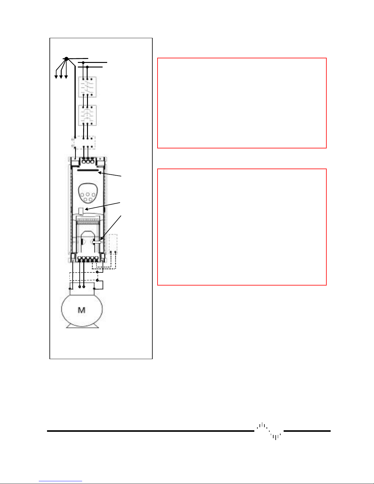
Each drive star
The earth cable must be sufficient to carry the maximum supply
fault current which normally will be limited by the fuses or MCB
Protect the drive by using slow-blowing HRC fuses or Circuit
Breaker located in the mains supply of the drive
§ Do not install any type of automatic switchgear between the
drive and the motor
§ Wherever control cabling is close to power cabling, maintain a
minimum separation of 100 mm (3.98”) and arrange crossings at
90
o
§ Ensure that screening or armouring of power cables is effected
in accordance with the connections diagram below
§ Ensure that all terminals are tightened to the appropriate torque
(see table, left)
connected to system
earth point
To
other
drives
L1 L2 L3
Earth
Isolator
Contactor,
Circuit Breaker,
or
Or Fuses
Optional
Filter
L1
L2
*
Help card
Optidrive1 size 2
IR lens
Cable
management
tie-wrap
ELECTRICAL INSTALLATION
WARNING
§ Optidrive1ph should be installed only by qualified electrical
persons and in accordance with local and national regulations and
codes of practice
§ Electric shock hazard! Disconnect and ISOLATE the
Optidrive1ph before attempting any work on it. High voltages are
present at the terminals and within the drive for up to 10 minutes
after disconnection of the electrical supply
§ Where the electrical supply to the drive is through a plug and
socket connector, do not disconnect until 10 minutes have elapsed
after turning off the supply
§ Ensure correct earthing connections, see diagram below
§
CAUTION
§ Ensure that the supply voltage and frequency correspond to the
rating of the Optidrive1ph as delivered
§ An isolator or similar should be installed between the power
supply and the drive
§ Never connect the mains power supply to the Optidrive1ph
output terminals U and V
§
U V W + BR
M1 M2
Optional
Braking
Resistor
Shielded motor
cable connects to
motor frame earth
page 4

Bardac
drives
Connect drive according to diagram below, ensuring that motor terminal box connections are correct (see diagram,
right). Refer to the ELECTRICAL DATA overleaf for the sizes of cabling and wiring.
It is recommended that the power cabling should be PVC-insulated shielded cable, laid in accordance with local
industrial regulations and codes of practice.
0-10V
4-20mA
0V
Digital I/P 1
Digital I/P 2
Digital I/P 3
+10V O/P
Analog I/P0VAnalog O/P0VRelay contact
1 2 3 4 5 6 7 8 9 10 11
Ω
500
0-10V
min.
analog
Relay ratings
30V dc, 5A
240V ac, 5A
Closed: Enable; Open: Disable
Analog I/P - Closed: A; Open :V
Closed: Preset 1; Open: Analog I/P
Relay common
O/P
* If fitted, a filter should be physically close to the Drive. For maximum effectiveness, the metal case of the filter and
the heat sink of the drive should be electrically connected, i.e., screw both to a metal backplate and ensure metal-tometal contact
Refer to the Digital Inputs table for details of the digital input functions 1 to 3
If shielded cabling is used for the control wiring, connect the cable screen to 0V of drive, terminals 1, 7 or 9
GROUNDING (EARTHING)
The ground terminal of each Optidrive1ph should be individually connected DIRECTLY to the site earth (ground)
busbar (through the filter if installed) as shown. Optidrive1ph ground connections should not loop from one drive to
another, or to, or from any other equipment. Ground loop impedance must conform to local industrial safety
regulations. To meet UL regulations, UL approved ring crimp terminals should be used for all earth wiring
connections.
OPERATION – BASICS + GETTING STARTED
WARNING
§ The STOP function does not remove potentially lethal high voltages. ISOLATE the drive and wait 10 minutes
before starting any work on it
§ If it is desired to operate the drive at any frequency/speed above the rated speed (P-09/ P-10) of the motor, consult
the manufacturers of the motor and the driven machine about suitability for over-speed operation
§ The fan (if fitted) to the heatsink of the Optidrive1ph starts automatically when the heatsink temperature reaches
approximately 40ºC. When the heatsink is at room temperature the fan will be stopped.
page 5
 Loading...