

Bardac OD-14075-IN, OD-12075-IN, OD-12150-IN, OD-14150-IN, OD-22150-IN User Manual
...
–
A
–
p
∆
A
A
V
It is the responsibility of the installer to
ensure that the equipment or system into
which the product is incorporated complies
with the EMC legislation of the country of
use. Within the European Union, equipment
into which this product is incorporated must
comply with 89/336/EEC,Electromagnetic
Compatibility.
Bardac
OPTIDRIVE
USER GUIDE
The level of integrity offered by the
Optidrive control functions – for example
stop/start, forward/reverse and maximum
speed, is not sufficient for use in safetycritical applications without independent
channels of protection. All applications
where malfunction could cause injury or
loss of life must be subject to a risk
assessment and further protection
provided where needed. Within the
European Union, all machinery in which
this product is used must comply with
Directive 89/392/EEC, Safety of Machinery.
In particular, the electrical equipment
should comply with EN60204-1.
All Invertek Drives Ltd (IDL) products carry a
2-year warranty, valid from the date of
manufacture.
Complete Warranty Terms and Conditions
are available upon request from your IDL
Authorised Distributor.
SAFETY NOTICES
WARNING!
WARRANTY
Carefully inspect the Optidrive before
installation to ensure it is undamaged
Store the Optidrive in its box until
required. Storage should be clean and
dry Temp. Range –40oC to +60oC
Install the Optidrive on a flat, vertical,
flame-resistant vibration-free mounting
within a suitable enclosure, according to
EN60529 if specific Ingress Protection
ratings are required. Installation required
in a pollution degree 2 environment.
Flammable material should not be
placed close to the drive
The entry of conductive or flammable
foreign bodies should be prevented
Max. ambient temperature 50
5oC. Refer to table on reverse side.
Relative humidity must be less than 95%
(non-condensing).
The Optidrive is suitable for use on a
circuit capable of delivering not more
than 5KA (50Hp) / 10KA (51-200HP)
symmetrical amperes, 480V maximum.
• Supply frequency 48 to 62 Hz.
• Max. permissible 3-phase supply
imbalance 3%.
• Max. ambient temperature 50 oC.
• Max. altitude 2000 m.
• Derate above 1000 m, 1% / 100 m.
• Derate output current 5%/ oC above
max. ambient temp up to 55oC
• I x t protection above 100% output
current.
• 150% overload protection for 60 sec.
• 175% overload allowable for 2 sec.
• Storage temperature -40 to +60 oC
CAUTION
o
GENERAL TECHNICAL DAT
C, min. –
All rights reserved. No part of this User Guide may be reproduced
User Guide
or transmitted in any form or by any means, electrical or
mechanical including photocopying, recording or by any
information storage or retrieval system without permission in
writing from the publisher.
The manufacturer accepts no liability for any consequences
resulting from inappropriate, negligent or incorrect installation, or
adjustment of the optional operating parameters of the drive or
from mismatching of the drive to the motor.
The contents of this User Guide are believed to be correct at the
time of printing. In the interests of a commitment to a policy of
continuous improvement, the manufacturer reserves the right to
change the specification of the product or its performance or the
contents of the User Guide without notice.
This variable speed drive product (Optidrive) is intended for
professional incorporation into complete equipment or systems. If
installed incorrectly it may present a safety hazard. The Optidrive
uses high voltages and currents, carries a high level of stored
electrical energy, and is used to control mechanical plant that may
cause injury. Close attention is required to system design and
electrical installation to avoid hazards in either normal operation
or in the event of equipment malfunction.
System design, installation, commissioning and maintenance
must be carried out only by personnel who have the necessary
training and experience. They must read carefully this safety
information and the instructions in this Guide and follow all
information regarding transport, storage, installation and use of
the Optidrive, including the specified environmental limitations.
Please read the IMPORTANT SAFETY INFORMATION below, and
all Warning and Caution boxes elsewhere.
WARNING is given where there is a hazard that could lead to injury
or death of personnel
CAUTION is given where there is a hazard that could lead to
damage to equipment
Copyright Invertek Drives Ltd © 2005
SAFETY
SAFETY NOTICES
Optidrives should be installed only by qualified electrical persons and in accordance with
local and national regulations and codes of practice. The Optidrive has an Ingress Protection
rating of IP20. For higher IP ratings, use a suitable enclosure.
Electric shock hazard! Disconnect and ISOLATE the Optidrive before attempting any work on
it. High voltages are present at the terminals and within the drive for up to 10 minutes after
disconnection of the electrical supply
Where supply to the drive is through a plug and socket connector, do not disconnect until 10
minutes have elapsed after turning off the supply
Ensure correct earthing connections
The earth cable must be sufficient to carry the maximum supply fault current which normally
will be limited by the fuses or MCB
The STOP function does not remove potentially lethal high voltages. ISOLATE the drive and
wait 10 minutes before starting any work on it
Parameter P-01 can be set to operate the motor at up to 60,000 rpm, hence use this
parameter with care
If it is desired to operate the drive at any frequency/speed above the rated speed (P-09/ P-10)
of the motor, consult the manufacturers of the motor and the driven machine about suitability
for over-speed operation
The fan (if fitted) to the heatsink of the Opti drive starts automatically when the heatsink
temperature reaches approximately 40ºC. When the heatsink is at room temperature the fan
will be stopped.
Ensure that the supply voltage, frequency and no. of phases (1 or 3 phase) correspond to
the rating of the Optidrive as delivered.
An isolator should be installed between the power supply and the drive.
Never connect the mains power supply to the Output terminals U,V,W.
Protect the drive by using slow-blowing HRC fuses or MCB located in the mains supply of
the drive
Do not install any type of automatic switchgear between the drive and the motor
Wherever control cabling is close to power cabling, maintain a minimum separation of 100
mm and arrange crossings at 90o
Ensure that screening or armouring of power cables is effected in accordance with the
connections diagram below
Ensure that all terminals are tightened to the appropriate torque (see table)
IMPORTANT SAFETY INFORMATION
Optidrive hardware and software are designed and tested to a high standard and failures are
unlikely.
Optidrive is designed to high standards of EMC. EMC data is provided in a separate EMC
Data Sheet, available on request. Under extreme conditions, the product might cause or
suffer disturbance due to electromagnetic interaction with other equipment. It is the
responsibility of the installer to ensure that the equipment or system into which the product
is incorporated complies with the EMC legislation of the country of use. Within the European
Union, equipment into which this product is incorporated must comply with 89/336/EEC,
Electromagnetic Compatibility.
When installed as recommended in this User Guide, the radiated emissions levels of all
Optidrives are less than those defined in the Generic radiated emissions standard EN610006-4. When correctly fitted with an Optifilter (Mains filter), the conducted emission levels are
less than those defined in the Generic radiated emissions standard EN61000-6-3 (class B)
for screened cable lengths of < 5m and with EN61000-6-4 (class A) for screened cable
lengths of < 25m.
Safety of machinery, and safety-critical applications
Electromagnetic Compatibility (EMC)
WARNING !
WARNING !
CAUTION
Bardac Corporat ion www.bardac.com
40 Log Canoe Circle, Stevensville, MD 21666 USA
USA Toll Free Phone: 1-888-667-7333 (1-888-ON SPEED)
International Phone: 410-604-3400 Fax: 410-604-3500
Made in the UK by Invertek Drives Ltd
The Optidrive conforms with the following standards
1) CE marked for low voltage directive
2) UL508C Power conversion equipment
3) IEC 664-1 Insulation coordination for equipment within low voltage systems
4) EN61800-3 Adjustable Speed electrical power drive systems – Part 3 (EMC)
5) EN 61000-6 / -2, -3, -4 Generic Immunity / Emissions standards (EMC)
STANDARDS CONFORMITY
Each drive star
∆
A
A
V
connected to system
earth point
To
other
drives
Earth
L1
L2
L3
Isolator
Contactor,
mcb or
Fuses
Optional
*
Filter
L1 L2 L3
Optidrive size 2
Optional
Braking
U V W + BR
U V W
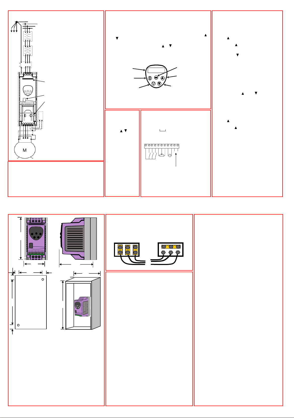
Connect drive according to diagram (above), ensuring that
motor terminal box connections are correct (see diagram,
below).
Refer to the ELECTRICAL DATA overleaf for the sizes of
cabling and wiring.
It is recommended that the power cabling should be 3-core or
4-core PVC-insulated screened cable, laid in accordance with
local industrial regulations and codes of practice.
Resistor
Screened motor
cable connects to
motor frame earth
ELECTRICAL INSTALLATION
* If fitted, a filter should be
physically close to the Drive.
For maximum effectiveness,
the metal case of the filter
and the heat sink of the drive
should be electrically
connected, ie screw both to a
metal backplate and ensure
metal-to-metal contact.
Size 6 Input Choke
Connection – When
connecting the choke
observe the following :-
Help card
IR lens
Cable
management
tie-wrap
i) The order of the input
phases (L1,L2,L3) is not
important.
ii) The choke can be
mounted to suit the wiring,
either above the drive or
anywhere in the panel.
Either set of terminals can
be used for the Input or
Output.
iii) The choke should NOT
be connected directly to the
drive to stop any
mechanical stress on the
terminals of the drive.
OPERATION – USING THE KEYPAD
When the drive is delivered from the factory, only the Standard
Parameter Set (see overleaf) is accessible.
To access the Standard Parameter Set, press the Navigate key ⇔ for
>1 sec.
• Scroll through P-01 to P-14 (and roll over to P-01) by pressing
or
• To display the parameter value, press ⇔
• To edit the parameter value, press or
• To return to the parameter number, press ⇔
• To store a value and / or exit from edit mode, press ⇔ for >1 sec
or press no button for >20 sec.
To access the Extended Parameter Set, set P-14 = 101 and press ⇔
DISPLAY
START
RESET/ STOP
NOTE To restrict unauthorised access, make P-37 = any value from 0
to 9999.
• When in the Extended Parameter Set (except P-00), the display
will revert to normal if no button is pressed for >20 sec.
TO RESTORE ALL
DEFAULT VALUES,
stop the drive and
when display shows
StoP, press and
hold the , and
STOP keys
simultaneously for 1
second. The display
will show P-dEF.
Access code P-37
will revert to 101 but
the hours-run meter
P-39 is not affected.
Press STOP to
resume normal
operation.
MANAGING THE KEYPAD
H 5 0 . 0
CONTROL TERMINAL BLOCK -
0V
Digital I/P 1
Digital I/P 2
1234567891011
Closed: Enable; Open: Disable
Closed: Preset 1; Open: Analog I/P
Default Status
0-10V
4-20mA
nalog I/P
Digital I/P 3
+10V O/P
0V
500
Ω
0-10V
min.
analog
O/P
Relay ratings
30V dc, 5A
240V ac, 5A
Analog I/P - Closed: A; Open :
nalog O/P
0V
DOWN
Relay contact
Relay common
NAVIGATE
UP
Refer to the
Digital Inputs
table overleaf
for details of
the digital input
functions 1 to 3
If screened
cabling is used
for the control
wiring, connect
the cable
screen to 0V of
drive, terminals
1,7 or 9.
OPERATING IN KEYPAD MODE
Set P-12 = 1(this allows the Optidrive to be
controlled from the keypad):
Enable the drive by closing digital input
1. The display will show StoP.
Press the START key. The display shows
H 0.0.
Press to increase speed
The drive will run forward, increasing
speed until is released. CAUTION: the
rate of acceleration is controlled by the
setting of P-03, check this before starting.
Either Press to decrease speed
The drive will decrease speed until τ is
released. The rate of deceleration is
limited by the setting in P-04
Or Press the STOP key. The drive will
decelerate to rest at the rate set in P-04.
The display will finally show StoP at
which point the drive is disabled
To preset a target speed prior to enable
press the stop key whilst the drive is
stopped. The display will show the target
speed, use the and to adjust as
required then press the Stop key to return
the display to StoP. Pressing the START
key will start the drive accelerating to the
target speed.
With P-12 set to 2:
Press the START key. The display
changes to H 0.0.
Press to increase speed
The drive will run forward, increasing
speed until is released. Acceleration is
limited by the setting in P-03. The
maximum speed is the speed set in P-01.
Press the START key again. The motor
will reverse its direction of rotation.
The operation of the keypad can be duplicated
using remote pushbuttons connected to the
control terminals, see Application Note AN21.
In this mode, if P30 is set to Auto-0..4, then
the drive will run as soon as the drive enable
is applied (terminal 1 & 2 is closed).
TO SAVE CHANGES to Parameter settings,
switch the power supply off and wait for the
drive to power down (screen blank) before
switching on.
NOTE that this assumes P-38 = 0 (default). If
P-38 = 1, changes are not saved.
W
A
B
C
B
D
D
D
HOLE
POSITIONS
FOR
MOUNTING
H
C
Optidrives can be installed side-by-side with their heatsink
flanges touching. This gives adequate ventilation space between
them. If the Optidrive is to be installed above another drive or
any other heat-producing device, the minimum vertical spacing
is 100mm. The enclosure should either be force-ventilated or
large enough to allow natural cooling (allow 0.1 m
drive rating).
The ground terminal of each Optidrive should be individually
connected DIRECTLY to the site earth (ground) busbar (through
the filter if installed) as shown. Optidrive ground connections
should not loop from one drive to another, or to, or from any
other equipment. Ground loop impedance must conform to local
industrial safety regulations. To meet UL regulations, UL
approved ring crimp terminals should be used for all earth wiring
connections.
MECHANICAL INSTALLATION
GROUNDING (EARTHING)
ENCLOSURE
W
3
per kW of
OPERATION – BASICS + GETTING STARTED
MOTOR TERMINAL BOX CONNECTIONS
Motors are connected in either STAR or DELTA. The motor
rating plate will indicate the voltage rating for the method
of connection, ensure that this matches the Optidrive
operating voltage.
(DELTA) connection
Υ (STAR) connection
U V W Wires from Optidrive
When delivered, the Optidrive is in the default state,
meaning that it is set to operate in terminal mode and
all parameters (P-xx) have the default values as
shown overleaf.
Connect a control switch between the control
terminals 1 and 2.
Connect a potentiometer (500 Ω min to 10 kΩ max)
between terminals 5 and 7, and wiper to terminal 6.
Set the control switch between pins 1 and 2 open
so that the drive is ‘disabled’.
With the potentiometer set to zero, switch on the
supply to the drive. The display will show StoP.
Close the control switch, terminals 1-2. The drive is
now ‘enabled’ and the output frequency/speed are
controlled by the potentiometer. The display shows
zero speed in Hz (H 0.0) with the potentiometer
turned to minimum.
Turn the potentiometer to maximum. The motor will
accelerate to 50Hz (the default value of P-01) under
the control of the accelerating ramp time P-03. The
display shows H 50.0 (50Hz) at max speed.
To display motor current (A), briefly press the
Navigate key ⇔.
Press ⇔ again to return to speed display.
To stop the motor, either turn the potentiometer back
to zero or disable the drive by opening the control
switch (terminals 1-2).
If the enable/disable switch is opened the drive will
decelerate to stop at which time the display will show
StoP. If the potentiometer is turned to zero and the
enable/disable is closed the display will show 0.0Hz, if
left like this for 20 seconds the drive will go into
standby mode, display shows Stndby, waiting for a
EASY START-UP
speed reference.
SIMPLE PARAMETER ADJUSTMENTS
The factory-set default parameter values may give satisfactory
performance, however certain adjustments may be beneficial.
Maximum and Minimum Speeds P-01 & P-02
Set P-01 to the maximum speed and P-02 to the minimum speed for
your application. These limits are mirrored for negative speeds. If a
non-zero minimum speed is set in P-02, the motor will ramp (P-03) to
this minimum speed as soon as the drive is enabled.
Acceleration and Deceleration P-03 & P04
Ramps which are too short will cause the drive to deliver currents in
excess of full load current and may result in it tripping out or the
motor stalling
Stop Mode P-05
Select method of stopping required when drive is disabled. Ramp to
stop (P-05 = 0) decelerates the motor at the rate set by deceleration
ramp time P-04. Freewheel/ Coast to stop (P-05=1) disables the drive
output immediately, allowing the motor to decelerate naturally due
to friction or under the control of a mechanical brake
Torque/Speed Characteristic P-06
Certain loads such as fans and centrifugal pumps need very little
torque at low speed. Set P-06=1 to reduce power loss at low speeds
for this load type.
Rated Current, Rated Frequency and Rated Speed P-08, P-09, P-10.
Parameters P-08 and P-09 should to be set to correspond with the
rated current and frequency shown on the motor rating plate.
Parameter P-10 is optional. If this parameter is set to zero (default
state), speed will be displayed in Hz; if speed indication is required
in rpm, enter the motor rated speed (speed at full load) from the
motor rating plate.
Voltage Boost P-11
Any load which is ‘sticky’ to start will benefit from a voltage boost
on starting. P-11 permits a boost of up to 25% of full motor voltage
to be applied.
NOTE: Use of this parameter increases motor heating at low speeds
Terminal or Keypad Control P-12
Terminal control (P-12=0) is used when the drive needs to be
controlled from some remote point, such as a control panel
interface or machine system.
Keypad control (P12=1 or 2) is used for local, manual control and
commissioning
Extended Parameter Set P15 to P-40 and P-00
The Extended Parameter Set is intended for use by specialist drives
engineers and technicians and will not generally be required for
• Provides a read only window into the motor control software
allowing
key internal values to be viewed. This is useful for following
signals
through the drive control system when troubleshooting.
• Access, scroll, change and exit are as for any other parameter.
The selected variable is at the left hand side of the display.
• There are 9 different windows listed below:
1 Unscaled analog input (%)
2 Speed ref. via scaled analog input (Hz)
3 Pre-ramp speed ref. (Hz)
4 Post-ramp speed ref. (Hz)
5 Not used
6 Stator field frequency (Hz)
7 Applied motor voltage (V)
8 DC bus voltage (V)
9 Internal thermistor (NTC) value
simple applications.
PARAMETER ZERO
 Loading...