

Page 1

INSTALLATION INSTRUCTIONS
SINGLE STAGE HEAT PUMPS
LOW VOLTAGE
CONTROL CIRCUIT WIRING
MODELS
W**H W**H*D
S**H S**H*D
T**H T**H*D
Bard Manufacturing Company, Inc.
Bryan, Ohio 43506
Since 1914...Moving ahead just as planned.
Manual : 2100-516H
Supersedes: 2100-516G
File: Volume III Tab 16
Date: 03-28-14
Manual 2100-516H
Page 1 of 19
Page 2

Contents
Installation Instructions
Wiring – Low Voltage Wiring
Operating Voltage Range
Low Voltage Connection
Figures
Figure 1 Basic HP w/Opt. Elec. Heat .....................5
Figure 2 HP w/Opt. MFAD, CRV & ERV Vent. Pkg.
w/Programmable T-Stat ...........................6
Figure 3 HP w/Opt. MFAD, CRV & ERV Vent. Pkg.
w/Non-Programmable T-Stat ....................7
Figure 4
w/Non-Programmable Thermostat with ...
CO2 Controller .........................................8
Figure 5 Heat Pump w/Opt. Economizer
"E" Vent Option ........................................9
Figure 6 HP w/Dehumidication Sequence & No
Vent Pkg. Using T-Stat Comb. ...............10
Figure 7 HP w/Dehumidication Sequence w/
Non-Programmable T-Stat ......................... 11
Figure 8 HP w/Dehumidication Sequence & Opt.
MFAD, CRV, & ERV Vent Pkg.
Using Elec. T-Stat with Combination
Temp. & Humidity Control ......................12
Figure 9 HP w/Dehumidication Sequence & Opt.
MFAD, CRV & ERV Vent. Pkg.
Using Non-Prog. T-Stat.
(No Occupied Signal) .............................13
Figure 10
MFAD, CRV & ERV Vent. Pkg.
Using Non-Prog. T-Stat. with
CO2 Controller ........................................14
Figure 11 Heat Pump w/CS2000A* ........................15
Figure 12 W**H1 Dehum. with Economizer and
#8403-060 Thermostat (EIFM)
"E" Vent Option ......................................16
Figure 13 1-Stage HP w/Opt. Elec. Heat with or w/o
Dehum. with ECONWM* Style Economizer
"W" or "T" Vent Option ...........................17
Figure 14 HP w/Opt. CRVMP Vent Pkg. with
Programmable T-Stat .............................18
Figure 15
with Non-Programmable T-Stat ............ 19
HP w/Opt. MF AD, CRV & ERV V ent. Pkg.
HP w/Dehumidication Sequence & Opt.
HP w/Opt. MFAD, CRV & ERV Vent Pkg.
.....................................3
..........................................3
...........................................3
Wiring Diagram
Figure 11 Heat Pump w/CS2000A* ........................15
Tables
Table 1 Diagram to Use w/Unit & Vents ................3
Table 2 Operating Voltage Range .........................3
Table 3 Wall Thermostat .......................................3
Table 4 Humidity Controls .....................................4
Table 5 CO2 Controller ..........................................4
Table 6 Thermostat Wire Size ...............................4
Manual 2100-516H
Page 2 of 19
Page 3
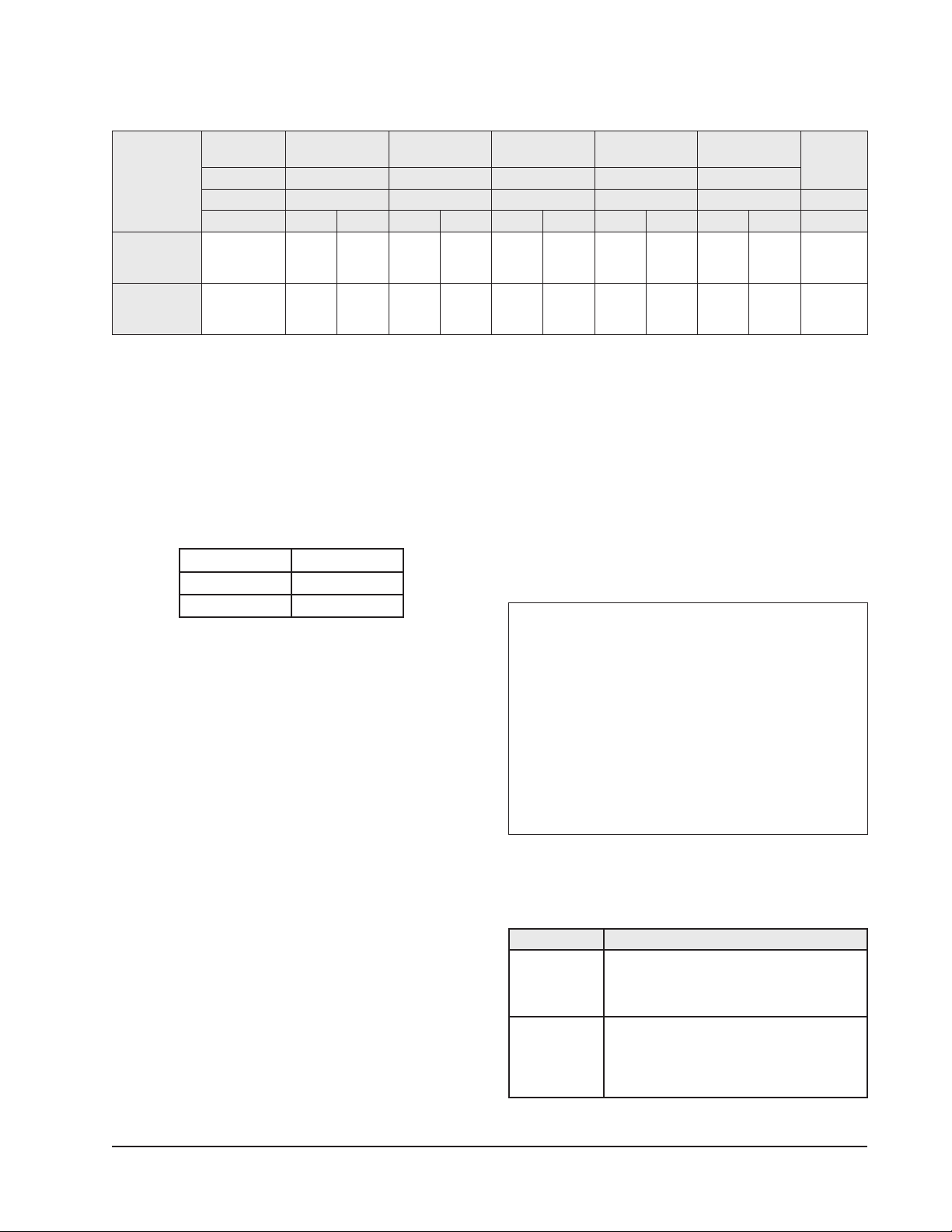
TABLE 1
DIAGRAM TO USE WITH UNIT AND VENTS
Vent None CRV, ERV, MFAD
System
Heat Pump
Heat Pump with
Dehumidication
Vent Code X R, M, V, P C E T, W, S
Thermostat Programmable Programmable Programmable Programmable Programmable All
Model Series No Yes No Yes No Yes No Yes No Yes
S**H
T**H
W**H
S**H*D
T**H*D
W**H*D
1 1 3 & 4 2 15 14 N/A 5 N/A 13 11
7 6 9 & 10 8 N/A 14 N/A 12 N/A 13 N/A
WIRING – LOW VOLTAGE WIRING
230/208V, 1 phase and 3 phase equipment dual primary
voltage transformers. All equipment leaves the factory
wired on 240V tap. For 208V operation, reconnect
from 240V to 208V tap. The acceptable operating
voltage range for the 240V and 208V taps are:
TABLE 2
OPERATING VOLTAGE RANGE
TAP RANGE
240V 253 – 216
208V 220 – 187
NOTE: Thevoltageshouldbemeasuredattheeldpower
connectionpointintheunitandwhiletheunit
isoperatingatfullload(maximumamperage
operatingcondition).
An 18 gauge copper, color-coded thermostat cable is
recommended. The connection points are shown in this
Manual. See Table above.
Low Voltage Connection
These units use a grounded 24-volt AC low voltage
circuit.
The “R” terminal is the hot terminal and the “C”
terminal is grounded.
“G” terminal is the faninput.
“Y” terminal is the compressorinput.
“B” terminal is the reversingvalveinput. The reversing
valve must be energized for heating mode.
“R” terminal is the 24 VAC hot.
“C” terminal is the 24 VAC grounded.
CRVMWH-3
CHCRV-5
EIFM
Economizer
ECONWM*
CS2000A*
“L” terminal is compressorlockoutoutput. This
terminal is activated on a high or low pressure trip by the
electronic heat pump control. This is a 24 VAC output.
“W2” terminal is second stage heat (if equipped).
“O1” terminal is the ventilationinput. This terminal
energizes any factory installed ventilation option.
“E” terminal is the
emergencyheatinput. This terminal
energizes the emergency heat relay.
“W3” terminal is the dehumidicationinput. This
terminal energizes compressor, blower and three-way
valve.
LOW VOLTAGE CONNECTIONS
FOR DDC CONTROL
Fan Only Energize G
Cooling Mode Energize Y, G
Heat Pump Heating Energize Y, G, B
2nd Stage Heating
Energize G, W2, Y, B
w/Heat Pump (if employed)
Ventilation Energize G, O1
Emergency Heat
Energize B, W2, E, G
Dehumidication EnergizeW3
TABLE 3
WALL THERMOSTAT
Part Number Predominate Features
8403-058
(TH5220D1151)
8403-060
(1120-445)
2 stage Cool, 2 stage Heat - Conventional
1 stage Cool, 2 stage Heat - Heat Pump
Electronic Non-Programmable
Auto or Manual changeover
3 stage Cool; 3 stage Heat
Programmable/Non-Programmable Electronic
HP or Conventional
Auto or Manual changeover
Dehumidication Output
Manual 2100-516H
Page 3 of 19
Page 4
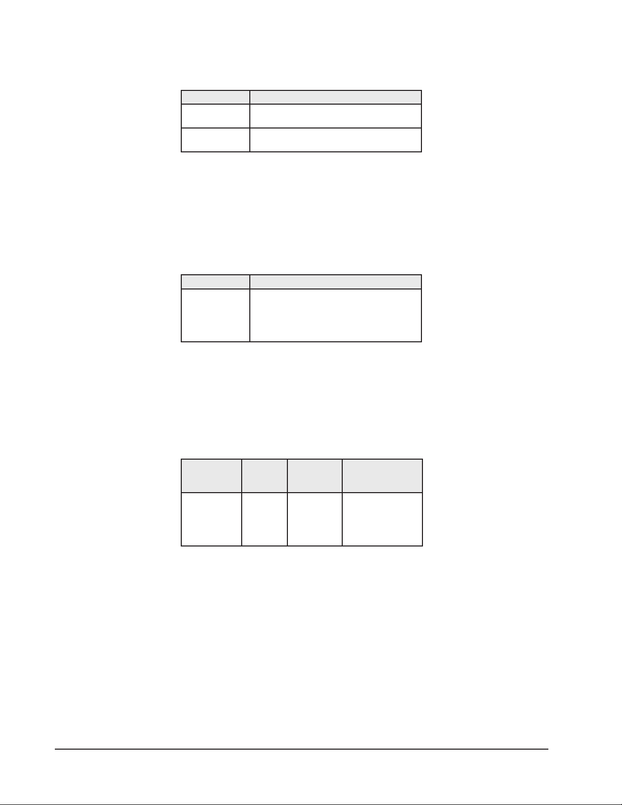
TABLE 4
HUMIDITY CONTROLS
Part Number Predominate Features
8403-038
(H600A1014)
8403-047
(H200-10-21-10)
SPDT switching, pilot duty 50VA @ 24V
Humidity range 20-80% RH
Electronic dehumidistat SPST closes-on-rise
Humidity range 10-90% with adjustable stops
TABLE 5
CO2 CONTROLLER
Part Number Predominate Features
Normally Open SPST relay closes-on-rise
8403-067
24V dual wave length sensor. Default setting
950ppm, adjustable to 0-2000ppm
Default off setting 1000ppm, adjustable to
0-200 ppm can be calibrated
Transformer
VA
55 2.3
TABLE 6
THERMOSTAT WIRE SIZE
FLA
Wire
Gauge
20 gauge
18 gauge
16 gauge
14 gauge
12 gauge
Maximum
Distance
In Feet
45
60
100
160
250
Manual 2100-516H
Page 4 of 19
Page 5
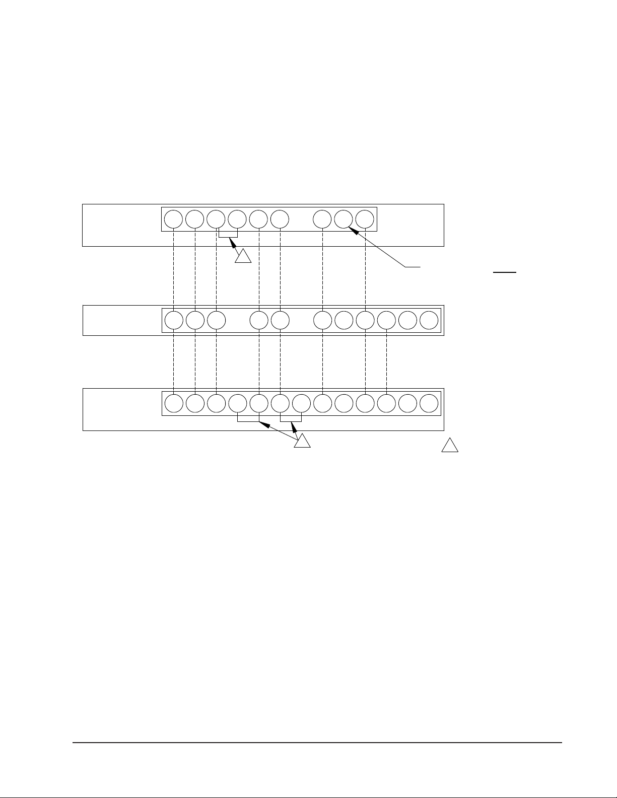
FIGURE 1
C
Factory Jumper Installed1
Unit
1
24V Low Voltage
Terminal Block
W3 E L DH O1W2W1Y1 BYRG
MIS-2645 C
Aux
Low Voltage Wiring Diagram
C G R Rc Y O/B
1
L E
W1/E
C
Bard part #8403-058
#TH5220D1151
Thermostat
2 Stage Heat
1 Stage Cool
Programmable
Electronic
Bard part #8403-060
AY2L
Y O/D
Thermostat
W2G R Y1 O/B
"L" is constant 24V output
when
thermostat is in Em Heat mode
BASIC HEAT PUMP WITH OPTIONAL ELECTRIC HEAT
NO ECONOMIZER or VENTILATION PACKAGES
Manual 2100-516H
Page 5 of 19
Page 6
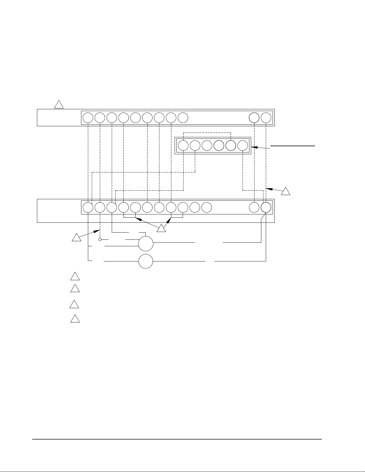
FIGURE 2
1 652 4
3
3
4
if optional CO controller is used.
Unit
C G R
YEY1
W2 W1
O1
DH
L
B W3
Terminal Block
24V Low Voltage
Ventilation Packaging with Programmable Thermostat (Recommended)
Figure 2
Low Voltage Wiring Diagram
C O/BY1RG W2
Y O/D
W1/E
Heat Pump with Optional MFAD, CRV, and ERV
Bard part #8403-060
Thermostat
Programmable
L A
Y2
Red
Orange
Black
2
Brown/White
Ventilation Packages
Electronic
Red
Factory Jumper Installed
Do not connect "A" from tstat #8403-060
Black
MFAD
2
ERV
CRV
during scheduled occupied periods
set to programmed for the "A" output to function
Must be configured to programmable and fan
2
2
4
optional CO controller is used.
Connect orange wire to "G" only if
3
1
2
1
MIS-2633 C
Optional CO Controller
Bard part #8403-067
HEAT PUMP WITH OPTIONAL MFAD, CRV & ERV
VENTILATION PACKAGING WITH PROGRAMMABLE THERMOSTAT (RECOMMENDED)
Manual 2100-516H
Page 6 of 19
Page 7

FIGURE 3
E
Unit
C R
Y EY1
Low Voltage Wiring Diagram
W1 O1
Black
LB
when
DH
Bard part #8403-058
W3
24V Low Volt age
Thermostat
#TH5220D1151
R
Red
Factory Jumper Inst al led
G
ERV
Orange
Black
Brown/White
CRV
Packages
Ventilation
1
whenever blower operates.
Add jumper, ventilation will be active
3
2
Do not connect orange w ire.
MFAD
Terminal Bl ock
3
2
1
Red
O/B
C
L
Y
2 Stage Heat
1 Stage Cool
thermostat is in Em Heat mode
W2
AUX
G
Rc
"L" is constant 24V output
1
MIS-2646 C
HEAT PUMP WITH OPTIONAL MFAD, CRV and ERV VENTILATION
PACKAGING WITH NON-PROGRAMMABLE THERMOSTAT (NO OCCUPIED SIGNAL)
Manual 2100-516H
Page 7 of 19
Page 8

FIGURE 4
Unit
C G R Y EY1 W2 W1 O1DH LB W3
1
Factory Jumper Inst al led
Low Voltage Wiring Diagram
C O/B
Y
R
L
AUX
Terminal Bl ock
E
24V Low Volt age
Bard part #8403-058
MFAD
Bard part #8403-067
2 Stage Heat
1 Stage Cool
Thermostat
1
Red
1
Orange
Optional CO Controller
Brown/White
#TH5220D1151
Ventilation Packages
Black
Red
526
3
2 4
G
2
1
2
ERV
CRV
is used.
only if optional CO controller
Connect orange wi re to "G"
Rc
Black
"L" is constant 24V output
when
thermostat is in Em Heat mode
2
MIS-2634 E
HEAT PUMP WITH OPTIONAL MFAD, CRV and ERV VENTILATION
PACKAGING WITH NON-PROGRAMMABLE THERMOSTAT WITH CO2 CONTROLLER
Manual 2100-516H
Page 8 of 19
Page 9

FIGURE 5
Unit
CRB
YEY1W2
W1
O1DH
Terminal Block
LW3G
Y2 Y1
Pink
Thermostat
Orange
Yellow
C
Black
24V Low Voltage
L
Purple
YO/D
Y1
1
Factory Jumper Installed.
2
be active as first stage cooling.
Must be configured for economizer with YO/D output to
These wires are used in special control applications only.
EF
Black
2 Stage Heat
Blue
3
1
Wiring Harness
Economizer
1
Bard part #8403-060
G
R O/B
2 Stage Cool
Low Voltage Wiring Diagram
Figure 5
Heat Pump with Optional Economizer
W1/E
W2
3
2
A
MIS-2648 C
HEAT PUMP WITH OPTIONAL EIFM ECONOMIZER
“E” VENT OPTION
Manual 2100-516H
Page 9 of 19
Page 10

FIGURE 6
C
Factory Jumper Installed.
Unit
A
G O1REY1
W2
Y2
DHLW1
Electronic
B
YO/D
Terminal Block
Figure 6
Low Voltage Wiring Diagram
C
O/B
RG
L
24V Low Voltage
Bard part #8403-060
Thermostat
using Thermostat part #8403-060 Combination Temperature and Humidity Controller.
Y1
Heat Pump with Dehumidification Sequence and No Ventilation Package
Programmable
W2
W1/E
W3Y
2
1
1
MIS-2636 A
Must be configured for "No economizer"
for YO/D to be active for humidity control
2
HEAT PUMP WITH DEHUMIDIFICATION SEQUENCE AND NO VENTILATION PACKAGE
USING THERMOSTAT #8403-060 COMBINATION TEMPERATURE & HUMIDITY CONTROLLER
Manual 2100-516H
Page 10 of 19
Page 11

FIGURE 7
C
Unit
C G R YEY1
Bard part #8403-038
E
O1DHLB
Terminal B lock
#TH5220D1151
W3
24V Low Voltage
1
Mechanical Humi dist at
L
W1
Red Yellow
6 5 3
4
1 Factory Jumper Instal l ed.
Jumper needs to be added.
Bard part #8403-047
Electronic Humidistat
R Y
W2
Thermostat
2 Stage Heat
1 Stage Cool
Bard part #8403-058
AUX
G Rc
O/B
2
1
Low Voltage Wiring Diagram
2
"L" is constant 24V output
when
thermostat is in Em Heat mode
MIS-2649 B
HEAT PUMP WITH DEHUMIDIFICATION SEQUENCE
WITH NON-PROGRAMMABLE THERMOSTAT
Manual 2100-516H
Page 11 of 19
Page 12

FIGURE 8
2
G
Block
Red
during scheduled occupied periods.
Figure 8
C
C
Unit
Low Voltage Wiring Diagram
#8403-060
E
Heat Pump with
Thermostat
24V Low
3
W3
3
Dehumidification
O/B
Orange
CRV
ERV
Voltage
Y2
RG
W2
YO/D
L
Y1
W1/E
A
Ventilation Packages
when optinal CO controller is used.
LY1 DHY B W1 O1R W2
2
and fan set to programmed fan for the "A" output to function
2
2
active for humidity control. Must be configured to programmable
Red
Terminal
Black
controller is used. Connect orange wire to "G" only
Must be configured to "no economizer" to make YO/D output
3
Brown/White
Bard part
Black
MFAD
Do not connect "A" from thermostat if optional CO
Packaging using Electronic Thermostat with Combination Temperature and Humidity Control
Sequence and Optional MFAD, CRV, and ERV Ventilation
with Optional CO Controller
Heat
Cool
2 Stage
2 Stage
1
Factory Jumper Installed
2
1
4 52231 6
MIS-2637 C
Optional CO Controller
Bard part #8403-067
HEAT PUMP WITH DEHUMIDIFICATION SEQUENCE & OPTIONAL MFAD, CRV & ERV VENTILATION
PACKAGING USING ELECTRONIC THERMOSTAT WITH COMBINATION TEMPERATURE &
HUMIDITY CONTROL WITH OPTIONAL CO2 CONTROLLER
Manual 2100-516H
Page 12 of 19
Page 13

FIGURE 9
Terminal B lock
Electronic Humidistat
Low Voltage Wiring Diagram
G
O/BY
R
Y1
AUX
L
Bard part #8403-047
2
24V Low Voltage
Bard part #8403-058
Rc
Thermostat
Ventilation
2 Stage Heat
1 Stage Cool
O1
MFAD
ERV
Red
1
Black
Brown/White
CRV
Black
Red Yellow
6
Packages
1
5
Orange
1 Factory Jumper Inst al l ed.
active whenever blower operates.
Add jumper, ventilation wi ll be
3
4
3
Bard part #8403-038
Mechanical Humidi st at
2
4
Jumper needs to be added.
3
Orange wire is not connected.
Unit
C G R Y E
RED
W2
C
DH LB W3
E
4
W1
"L" is constant 24V output
when
thermostat is in Em Heat mode
MIS-2638 C
HEAT PUMP WITH DEHUMIDIFICATION SEQUENCE & OPTIONAL MFAD, CRV & ERV VENTILATION
PACKAGING USING A NON-PROGRAMMABLE THERMOSTAT (NO OCCUPIED SIGNAL)
Manual 2100-516H
Page 13 of 19
Page 14

FIGURE 10
2
Cool
Unit
24V Low Volt age
Low Voltage Wiring Diagram
Terminal Bl ock
Heat
2 Stage
Y1
1
Bard part #8403-058
Jumper needs to be added.
#TH5220D1151
1
Connect Orange wire to "G".
Mechanical Humidi st at
Black
MFAD
Thermostat
ERV
2
Red
Ventilation
CRV
1 Stage
Optional CO Controller
Bard part #8403-038
Factory Jumper Inst al led.
Bard part #8403-047
3
Electronic Humidistat
3
1
4
356
YellowRed
Brown/White
Black
Orange
Red
AUX
C G R Y
Packages
W2 W3O1DH
L
B W1
E
2
E
Rc L
G R
Y O/B
Bard part #8403-067
C
1
65432
"L" is constant 24V output
when
thermostat is in Em Heat mode
MIS-2639 E
HEAT PUMP WITH DEHUMIDIFICATION SEQUENCE & OPTIONAL MFAD, CRV & ERV VENTILATION
PACKAGING USING A NON-PROGRAMMABLE THERMOSTAT WITH CO2 CONTROLLER
Manual 2100-516H
Page 14 of 19
Page 15

JUMPER IS FACTORY INSTALLED.
LIGHTING CONTROL CIRCUIT
IS OPTIONAL AND FIELD
SUPPLIED. LIGHTING CONTROL
RELAY REQUIRES NORMALLY
CLOSED CONTACTS AND MUST
BE SIZED ACCORDING TO
CONTROLLED LOAD.
2
1
CONTROLLER BARD P/N 8403-060
90
SEARCH-TIME
84
LIGHTS
TEMPERATURE SWITCHES
LEARN
FUNCTION SWITCHES
DEMAND 1
DEMAND 2
AUX
STAGE
N/C
RATE
MODE
PRE P
RECOMMENDED SWITCH SETTINGS SHOWN BELOW
48
54
58
62
68
65
81
78
1
TEMPERATURE/HUMIDITY
Figure 11
DO NOT CONNECT "L" UNTIL AFTER
TERMINALS
G
O/B
OPTIONAL
OR
C
E
R
E
O/B
CGR
Y
Y1 B
CRV
6
UNIT 24V
O
G
Y
W1
C
DEHUMIDSTAT
THERMOSTAT TH5220D1151
WERV
L
W1/E
ON PAGE 3
L
1
HUMIDITY CONTROLLER
L
SEARCH TIME DETAIL
TO CS2000 = YES
FACTORY JUMPER - SEE
AND ORANGE WIRES
WH/SH HEAT PUMP CONNECTION DIAGRAM
RC
CONTACTS
OPEN
NORMALLY
(OPTIONAL)
DETECTOR
MOTION
LIGHTING CONTROL
CONTROLLER
PACKAGE (OPTIONAL)
SETTINGS).
INSTALLED IN HEAT PUMP
BARD P/N 8403-058
HP WITH CS2000
OVERIDE
ENERGY MONITOR
HVAC
NO C NCDOORPRECOND
- +
REMOTE
PWR
- +
C NC
REM
W3
PWR
3
- +
AREA OCCUP.
4
VENT HVAC FAN
R
NOTE: IF FACTORY INSTALLED
5
MAN.
NO C NC
H600A1014
R
H200-10-21-10
CS2000A2
8403-060 CONTROLLER IS CONFIGURED
BARD VENTILATION
BLUE
(SEE STEP 2, FUNCTION SWITCH
CONNECTIONS USED ONLY
HUMIDITY
DISCONNECT AND TAPE RED
8403-038
CIRCUIT THAT MUST BE FACTORY
RELAY NORMALLY
FIELD SUPPLIED
CONTROL
01
8403-047
2
RED
MUST ALSO BE CONNECTED
YELLOW
FOR PRE-PURGE OPERATION
FOR OPTIONAL DEHUMIDIFICATION
Aux
W2
CLOSED CONTACTS
MANUAL SWITCH
LIGHTING
NC C NO C NC
W2
YO/D
Y1
(24 HRS)
IF OPTIONAL VENT PACKAGE IS
INSTALLED, THE "G" WIRE MUST
BE CONNECTED TO ASSURE
CONTINUOUS BLOWER DURING
OCCUPIED PERIODS WHEN VENT
SYSTEM IS "ON". THE "G" WIRE
1
4093-140 L
BK
BR/W
FIGURE 11
HEAT PUMP WITH CS2000A2
Manual 2100-516H
Page 15 of 19
Page 16

FIGURE 12
*ELECTRICAL SHOCK HAZARD
*DISCONNECT POWER BEFORE
SERVICING.
DANGER
!
1
24
56
3
1
24
56
3
Yellow
Low Voltage
Blue
W3
Black
*Thermostat Model Configuration Notes:
W**H1Dehum.with Econ.
Part #8201-062
W2
W1E
RG
C
Thermostat Part#8403-060*
W2GRCE
L O/B
YOD
Y2 Y1
L W1 O/BY
WH Unit
Y1
Vent Option
and #8403-060 Thermostat
Dehum.Relay
Heat Relay
Term.Strip
Economizer
Part #8201-062
EF
Y2 Y1
Black
Green
Red
White
Brown
Orange
Blue
Light Blue
Light Blue
Orange
Black
Blue
Pink
Purple
1.) Configured for "Heat Pump"
2.) Configured for "Multi-Stage"
3.) Configured for "No Economizer"
4.) Configured CS2000A Attached = NO
4200-001 B
RELAYS AND
ASSOCIATED WIRING
ARE FIELD INSTALLED
W**H1 DEHUM. WITH ECONOMIZER
& #8403-060 THERMOSTAT (EIFM)
“E” VENT OPTION
Manual 2100-516H
Page 16 of 19
Page 17

FIGURE 13
W1/E
Y2
1
is 10V (100%).Depending upon applicationmay require setting to lower value.
YO/D
CRB
YE
Must be configured for heat pump / multistage/ no economizer/
2
3
Low Voltage Wiring Diagram
2
Y1
W2
L
24V Low Voltage
W2
Terminal Block
W1
Wiring Harness
to enable YO/D output to be active as dehumidification output
L
W3
O1
G
Thermostat
Factory Jumper Installed.
Economizer
part #8403-060
G
R O/B
DH
C
A
3
1
Must be energized to enable minimum position. NOTE: Economizer ControlDefault Setting
Y1
Yellow
Black
Blue
Red
Yellow/red
Brown/white
Pink
Purple
Orange
Yellow/White
MIS-2981 B
1-STAGE HEAT PUMP WITH OPTIONAL ELECTRIC HEAT
WITH OR WITHOUT DEHUMIDIFICATION
WITH ECONWM STYLE ECONOMIZER
“W” OR “T” VENT OPTION
Manual 2100-516H
Page 17 of 19
Page 18

FIGURE 14
3
652 41
3
during scheduled occupied periods
set to programmed for the "A" output to function
Bard part #8403-067
Factory Jumper Installed
Unit
C G R
YEY1
W2 W1
O1
DH
L
B W3
Terminal Block
24V Low Voltage
1
Low Voltage Wiring Diagram
C O/BY1RG W2
Y O/D
W1/E
Bard part #8403-060
Thermostat
Programmable
L A
Y2
Yellow
Black
Orange
Electronic
if optional CO controller is used.
Do not connect "A" from tstat #8403-060
Must be configured to programmable and fan
2
Package
Ventilation
Wire only needed for dehumidification units
3
2
CHCRV-5
Red
CRVMWH-3
OR
4
1
2
4
Optional CO Controller
2
MIS-2997 C
HEAT PUMP WITH OPTIONAL CRVMWH-3 OR CHCRV-5
VENTILATION PACKAGING WITH PROGRAMMABLE THERMOSTAT (RECOMMENDED)
Manual 2100-516H
Page 18 of 19
Page 19

FIGURE 15
Y
L
1 Stage Cool
2 Stage Heat
Thermostat
#TH5220D1151
Bard part #8403-058
AUX
G R Rc
O/B
C
Low Voltage Wiring Diagram
E
1
Unit
C
Factory Jumper Installed
G2R
EY1W2 W1 O1DHLB
Ventilation
Y
Black
W3
Package
24V Low Voltage
Add jumper, ventilation will be active
Terminal Block
Red
1
whenever blower operates.
Orange
1
2
Yellow
CHCRV-5
OR
CRVMWH-3
MIS-2998 A
HEAT PUMP WITH OPTIONAL CRVMWH-3 OR CHCRV-5 VENTILATION
PACKAGING WITH NON-PROGRAMMABLE THERMOSTAT (NO OCCUPIED SIGNAL)
Manual 2100-516H
Page 19 of 19
 Loading...