

Bard WG301, WG361, WG422, WG481, WG601 Installation Instructions Manual
INSTALLATION
INSTRUCTIONS
READ ALL INSTRUCTIONS CAREFULLY BEFORE
BEGINNING THE INSTALLATION.
THE INSTALLATION MUST COMPLY WITH THESE
INSTRUCTIONS AND THE REQUIREMENTS OF ALL
GOVERNING CODES AND ORDINANCES FOR THE
INSTALLATION LOCATION.
WG - SERIES
COMBINATION GAS/ELECTRIC
WALL-MOUNT
MODELS:
WG241 WG301 WG361
WG422 WG481 WG601
WARNING
IT IS THE RESPONSIBILITY OF INSTALLER TO KNOW
AND UNDERSTAND ALL OF THESE REQUIREMENTS.
FAILURE TO DO SO COULD CREATE A HAZARD
RESULTING IN PROPERTY DAMAGE, BODILY INJURY,
OR DEATH.
Bard Manufacturing Company
Bryan, Ohio 43506
Since 1914...Moving ahead just as planned.
Manual No.: 2100-365K
Supersedes: 2100-365J
File: Volume III, Tab 20
Date: 06-10-05
©
Copyright 2004

CONTENTS
Page
Getting Other Information and Publications .............. 1
WG Series Model Nomenclature............................... 2
Ventilation Options .................................................... 2
Air Conditioning Module Options ............................... 3
1. Important ............................................................ 3
2. Application .......................................................... 3
3. Duct Work .......................................................... 3
4. High Altitude Applications ................................... 7
5. Transportation Damage ...................................... 7
6. Installation .......................................................... 7
7. Wall Mounting .................................................... 8
8. Mounting the Unit ............................................... 8
9. Clearances ....................................................... 14
10. Vent Terminal and Combustion Inlet Hood ....... 15
11. Optional Vertical Venting .................................. 15
12. Vent Resizing Instructions ................................ 16
13. Fresh Air Intake ................................................ 16
14. Condensate Drain ............................................ 16
15. Wiring – Main Power ........................................ 17
16. Wiring – Low Voltage Wiring ............................ 18
17. Thermostats...................................................... 18
18. Gas Supply & Piping ........................................ 21
19. Manifold Pressure Adjustment.......................... 22
Page
20. Checking Gas Input Rate ................................. 22
21. Standard Orifice Sizing & High
Altitude Derate.................................................. 24
22. Conversion of Gas Input BTUH From High
to Low Rating ................................................... 27
23. Measuring Air Temperature Rise ...................... 27
24. Filters................................................................ 28
25. Compressor Control Module............................. 28
26. Lighting & Shutdown Instructions ..................... 30
27. Service Agency Procedures ............................. 31
28. Maintaining Unit in Good Working Order .......... 31
29. Replacement Parts ............................................ 32
30. Sequence of Operation – Heating .................... 33
31. Sequence of Operation – Cooling .................... 33
32. Indoor Blower Operation .................................. 34
33. Pressure Service Ports ..................................... 44
34. Refrigerant Charge ........................................... 45
35. Fan Blade Setting Dimensions ......................... 45
36. Low NOx Burner Assembly "N" Suffix
Models Only – U.S. Installations Only .............. 45
Index – Wiring Diagrams ......................................... 46
Wiring Diagrams ............................................. 47 – 70
i.

CONTENTS
Page
FIGURES
Figure 1 Unit Dimensions ..................................... 6
Figure 2 Mounting Instructions – WG24-36 ......... 9
Figure 2A Mounting Instructions – WG42-60 ....... 10
Figure 3 Combustible Clearance – WG24-36 ..... 11
Figure 3A Combustible Clearnace – WG42-60 .....11
Figure 4 Wall Mounting Instructions ................... 12
Figure 5 Wall Mounting Instructions ................... 12
Figure 6 Common Wall Mounting Installations ... 13
Figure 7 Location of Vent Terminal in Shipping .. 14
Figure 8 Vent Terminal & Combustion
Air Intake .............................................. 15
Figure 9 Fresh Air Damper ................................. 16
Figure 10 Installation of Flexible Conduit ............. 18
Figure 11 Low Voltage Wiring .............................. 19
Figure 12 Gas Pipe Connection ........................... 20
Figure 13 Proper Piping Practice ......................... 21
Figure 14 Acces Internal Filter Thru
Upper Service Door .............................. 28
Figure 15 Lighting & Shutdown Instruction Label . 30
Figure 16 Top View of Gas Control ...................... 31
Figure 17 Sequence of Operation – Electronic
Blower Control ...................................... 33
Figure 18 Furnace Control Board &
Blower Control ...................................... 34
Figure 19 460V Blower Motor Wiring Options –
WG24-36 Models ................................. 35
Figure 20 460V Blower Motor Wiring Options –
WG42-60 Models ................................. 36
Figure 21 Fan Blade ............................................. 45
Figure 22 Low NOx Insert .................................... 45
Page
TABLES
Table 1 Specifications – WG24-36 Models ........... 4
Table 1A Specifications – WG42-60 Models ........... 5
Table 2 Minimum Installation Clearances ........... 14
Table 3 Thermostat Wire Size ............................ 18
Table 4 Wall Thermostat &
Subbase Combinations .......................... 18
Table 5 Length of Standard Pipe Threads .......... 21
Table 6 Gas Pipe Sizes – Natural Gas ............... 21
Table 7 Natural Gas Derate Capacities
For All Models ........................................ 24
Table 8 Natural Gas Orifice Tables – WG24-36 .. 25
Table 8A Natural Gas Orifice Tables – WG42-60 .. 26
Table 9 Motor Speed Taps .................................. 34
Table 10 WG241 Indoor Blower Performance ...... 37
Table 11 WG301 Indoor Blower Performance ...... 38
Table 12 WG361 Indoor Blower Performance ...... 39
Table 13 WG422 Indoor Blower Performance ...... 40
Table 14 WG481 Indoor Blower Performance ...... 41
Table 15 WG601 Indoor Blower Performance ...... 42
Table 16 Integrated Furnace & Blower
Control Operation ................................... 43
Table 17 Cooling Pressure Table .......................... 44
Table 18 Refrigerant Charge ................................ 45
Table 19 Fan Blade Dimension ............................. 45
ii.

Getting Other Information and Publications
These publications can help you install the furnace. You
can usually find these at your local library or purchase
them directly from the publisher. Be sure to consult
current edition of each standard.
National Fuel Gas Code ......... ANSI Z223.1 / NFPA 54
National Electrical Code ..................... ANSI / NFPA 70
Standard for the Installation ............. ANSI / NFPA 90A
of Air Conditioning and
Ventilating Systems
Standard for Warm Air ..................... ANSI / NFPA 90B
Heating and Air Conditioning
Systems
Standard for Chimneys, ................................. NFPA 211
Fireplaces, Vents, and Solid
Fuel Burning Appliances
Load Calculation for............................ ACCA Manual J
Residential Winter and
Summer Air Conditioning
Duct Design for Residential ............... ACCA Manual D
Winter and Winter Air Conditioning
and Equipment Selection
FOR MORE INFORMATION, CONTACT
THESE PUBLISHERS:
ACCA Air Conditioning Contractors of America
1712 New Hampshire Avenue, NW
Washington, DC 20009
Telephone: (202) 483-9370
ANSI American National Standards Institute
11 West Street, 13th Floor
New York, NY 10036
Telephone: (212) 642-4900
Fax: (212) 302-1286
ASHRAE American Society of Heating Refrigerating,
and Air Conditioning Engineers, Inc.
1791 Tullie Circle, NE.
Atlanta, GA 30329-2305
Telephone: (404) 636-8400
Fax: (404) 321-5478
NFPA National Fire Protection Association
Batterymarch Park
P.O. Box 9101
Quincy, MA 02269-9901
Telephone: (800) 344-3555
Fax: (617) 984-7057
CSA Canadian Standards Association
178 Rexdale Boulevard
Rexdale, Ontario
Canada. M9W 1R3
Telephone: (416) 447-4044
Canadian Electrical Code ............................. CSA C22.1
Canadian Installation Code
CAN/CGA B149
Manufactured under the following U.S. patent numbers:
5,485,878; 5,002,116; 4,924,934; 4,875,520; 4,4825,936
COPYRIGHT SEPTEMBER 2003
BARD MANUFACTURING COMPANY
BRYAN, OHIO 43506 USA
Manual 2100-365K
Page 1
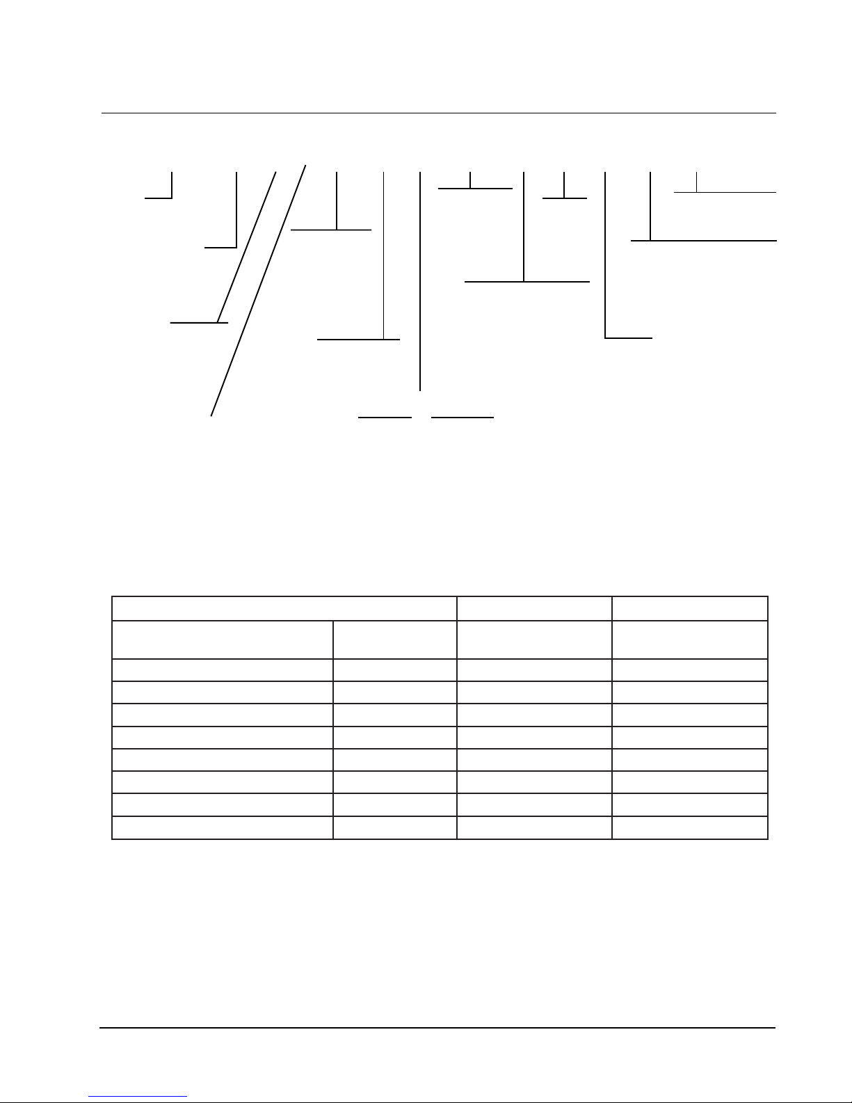
WALL MOUNT GAS/ELECTRIC GENERAL
MODEL NUMBER NOMENCLATURE
WG 42 1 – A X C X X X X X X
MODEL
Wall Mount Gas/Electric
COOLING CAPACITY
24 = 2 ton
30 = 2.5 ton
36 = 3 ton
42 = 3.5 ton
48 = 4 ton
60 = 5 ton
REVISION
LEVEL
FEATURE
(-) = Standard
D = Dehumidification
C = Canadian Approval
VENT
See Table Below)
(
VOLTAGE
A = 230/208-60-1
B = 230/208-60-3
C = 460-60-3
EMISSIONS
X = Standard
N = NOx Certified
HEATING INPUT
2 - 3 Ton 3.5 - 5 Ton
A = 45,000 B = 75,000
B = 67,500 C = 100,000
C = 90,000 D= 125,000*
*125,000 BTU input model is not NOx certified.
VENTILATION OPTIONS
COLOR
X = Beige
(Standard)
4 = Gray
FILTER
X = 2" Pleated (Standard)
W = 1" Washable
CONTROL OPTIONS
(See Table page 3)
COIL OPTIONS
X = Standard
1 = Phenolic coated evaporator
2 = Phenolic coated condenser
3 = Phenolic coated both coils
OUTLET
X = Front (Standard)
T=Top
sledoM63GW,03GW,42GW06GW,84GW,24GW
dellatsnIyrotcaF
noitpircseD
.oNedoC
dellatsnIdleiF
.oNtraP
repmaDriAhserFcirtemoraBX3-DAFBGW5-DAFBGW
etalPffO-knalBB3-POBGW5-POBGW
repmaDriAhserFdezirotoMM3-DAFMGW5-DAFMGW
nruteRgnirpS-rotalitneVlaicremmoCV3-SVRCGW5-SVRCGW
nruteRrewoP-rotalitneVlaicremmoCP3-PVRCGW5-PVRCGW
gnitaludoMylluF-rezimonocE 1 E3-MFIEGW5-MFIEGW
tloV032-rotalitneVyrevoceRygrenER3A-VREGW5A-VREGW
tloV064-rotalitneVyrevoceRygrenER3C-VREGW5C-VREGW
1 Low ambient control is required with economizer for low temperature compressor operation
dellatsnIdleiF
.oNtraP
Manual 2100-365K
Page 2
AIR CONDITIONING MODULE OPTIONS
1
MCC
DTSDTS
DTSDTS
DTSDTS
STD = Standard equipment.
1
CCM Compressor control module has adjustable 30 second to 5 minute delay-on-break
timer. On initial power up, or any time the power is interrupted, the delay-on-make
will be 2 minutes plus 10% of the delay-on-break setting. There is no delay-onmake during routine operation of the unit. The module also provides the lockout
feature (with 1 retry) for high and/or low pressure controls, and a 2 minute timed
2
3
4
bypass for low pressure control.
HPC High pressure control is auto reset. Always used with compressor control module
(CCM) which is included. See note
LPC Low pressure control is auto reset. Always used with compressor control module
(CCM) which is included. See note
LAC Low ambient control permits cooling operation down to 0°F.
2
3
CPH
CPL
%
%%
4
dellatsnIyrotcaF
CAL
%
edoC
G61-AMC
H81-AMC
I6-AMC
dellatsnIdleiF
traP
1.
1.
CAUTION
During the initial firing of the burners there will probably be some amount of smoke issued to the
circulating air stream as the result of residual oil burning off of the heat exchanger tubes. This oil
is required during the forming process of the stainless steel heat exchanger tubes to facilitate the
bending. OSHA or the National Toxicology Program does not list the oil as a carcinogen. In
vapor form this may be irritating to the eyes or could cause headaches. This is a one-time
occurrence, and ventilation of the space may be required depending upon the space being
conditioned.
1. IMPORTANT
The equipment covered in this manual is to be installed
by trained, experienced service and installation
technicians. All duct work or portions thereof not in
the conditioned space should be properly insulated in
order to both conserve energy and prevent condensation
or moisture damage.
2. APPLICATION
This is a fan-assisted forced air gas furnace with
electric air conditioning for outdoor installation. A fanassisted furnace is equipped with an integral
mechanical means to draw products of combustion
through the combustion chamber and heat exchanger.
The furnace installation must conform with local
building codes and ordinances or, in their absence, with
the National Fuel Gas Code ANSI Z223.1 or CAN/
CGA-B149.1, latest edition, and the National Electrical
Code ANSI/NFPA-7 or CSA C22.1, latest edition. It is
the personal responsibility and obligation of the
purchaser to contact a qualified installer to assure that
installation is adequate and is in conformance with
governing codes and ordinances.
3. DUCT WORK
The unit is designed for use with or without duct work.
See Warning on Page 7. Flanges are provided for
attaching the supply and return ducts. These
instructions explain the recommended method to install
the air cooled self-contained electric air conditioning
and gas heating unit and the electrical wiring
connections and gas piping to the unit. The refrigerant
system is completely assembled and charged. All
internal wiring is complete.
These instructions and any instructions packaged with
any separate equipment required to make up the entire
heating/cooling system should be carefully read before
beginning the installation. Note particularly “Starting
Procedure” and any tags and/or labels attached to the
equipment.
All duct work, supply and return, must be properly sized
for the design air flow requirement of the equipment.
Air Conditioning Contractors of America (ACCA) is an
excellent guide to proper sizing.
Refer to Tables 10, 11, 12, 13, 14 and 15 in this Manual
for maximum static pressure available for duct design.
Manual 2100-365K
Page 3
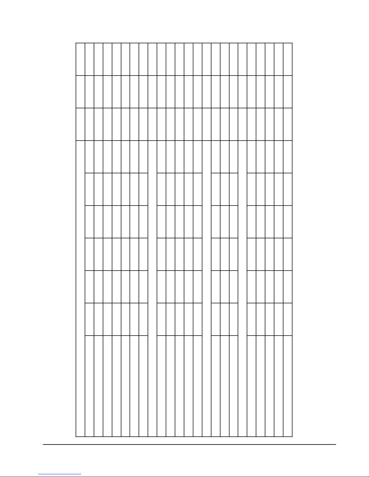
TABLE 1
SPECIFICATIONS
SNOITACIFICEPS
WG24, WG 30 AND WG36 MODELS
1-06-802/0323-06-802/0323-06-0641-06-802/0323-06-802/0323-06-0641-06-802/0323-06-02/0323-06-064
352-791352-781605-414352-791352-781605-414352-791352-781605-414
914172261962819
yticapmAtiucriCmuminiM
egnaRegatloVgnitarepO
ledoMA-142GWB-142GWC-142GWA-103GWB-103GWC-103GWA-163GWB-163GWC-163GW
ZH06–gnitaRlacirtcelE
Manual 2100-365K
Page 4
802/032802/032064802/032802/032064802/032802/032064
1/0501/5/11/0501/5/11/0501/5/11/0501/5/11/0501/5/11/0501/5/11/0501/5/11/0501/5/11/0501/5/1
5.01/5.90.7/5.64 5.31/5.215.9/0.95 5.71/0.710.11/5.015
01214101214180141
llorcSllorcSllorcSllorcSllorcSllorcSllorcSllorcSllorcS
012141012141010141
030251535251045251
eziSeriWdnuorG
*eziSeriWdleiF
epyTrosserpmoC
rosserpmoC
stloV
**.xaM–esuFyaleD
45/4554/5422/2237/3736/3613/13001/00177/7793/93
217.74 1.415.95 5.710.115.5
tnerruCnoitceleStiucriChcnarB
spmAdaoLdetaR
spmArotoRkcoL
5.15.18.05.15.18.05.15.18.0
DPS/MPR/PH–rotoMnaF
rosserpmoCdnarotoMnaF
spmA–rotoMnaF
MFC/AID–naF
3/059/4/13/059/4/13/059/4/13/5701/3/13/5701/3/13/5701/3/13/5701/3/13/5701/3/13/5701/3/1
0091–"020091–"020091–"020091–"020091–"020091–"020091–"020091–"020091–"02
rotaropavEdnarotoM
52.–00852.–00852.–00853.–000153.–000153.–000152.–001152.–001152.–0011
252x02252x02252x02252x02252x02252x02252x02252x02252x02
8.18.18.02.22.21.12.22.21.1
DPS/MPR/PH–rotoMrewolB
.P.S.E&gniooCMFC
spmA–rotoMrewolB
777777797979686868
.).zo22-R(egrahC
)sehcnI(seziSretliF
Maximum time delay fuse or HACR Type circuit breaker
75 degree C Copper wire size
**
*
TABLE 1A
SPECIFICATIONS
433221441351
5.12/1231/5.212.603/725.91/719
SNOITACIFICEPS
131/13118/1964961/961731/73126
22314.6035.919
WG42, WG48 AND WG60 MODELS
1-06-802/0323-06-802/0323-06-0641-06-802/0323-06-802/0323-06-0641-06-802/0323-06-02/0323-06-064
235231
yticapmAtiucriCmuminiM
egnaRegatloVgnitarepO352-791352-781605-414352-791352-781605-414352-791352-781605-414
ledoMA-224GWB-224GWC-224GWA-184GWB-184GWC-184GWA-106GWB-106GWC-106GW
ZH06–gnitaRlacirtcelE
5351055351065402
05
eziSeriWdnuorG010141010141010121
**.xaM–esuFyaleD
*/eziSeriWdleiF884188418821
5.91/125.41/5.318
spmAdaoLdetaR
epyTrosserpmoCllorcSllorcSllorcSllorcSllorcSllorcSllorcSllorcSllorcS
rosserpmoC
stloV802/032802/032802/032064802/032802/032802/032802/032064
721/72188/8844
12516.7
tnerruCnoitceleStiucriChcnarB
DPS/MPR/PH–rotoMrewolB3-0501-2/13-0501-2/13-0501-2/13-0501-2/13-0501-2/13-0501-2/13-0501-2/13-0501-2/13-0501-2/1
DPS/MPR/PH–rotoMnaF2-058-3/12-058-3/11-058-3/12-058-3/12-058-3/11-058-3/12-058-3/12-058-3/11-058-3/1
rosserpmoCdnarotoMnaF
spmArotoRkcoL
spmA–rotoMnaF5.25.23.15.25.23.15.25.23.1
rotaropavEdnarotoM
MFC/AID–naF0072-"420072-"420072-"420072-"420072-"420072-"420072-"420072-"420072-"42
.P.S.E&gniooCMFC53.-003153.-003153.-003183.-055183.-055183.-055103.-056103.-056103.-0561
spmA–rotoMrewolB4.34.35.14.34.35.14.34.35.1
101101101611611611341341341
.).zo22-R(egrahC
)sehcnI(seziSretliF2x03x022x03x022x03x022x03x022x03x022x03x022x03x022x03x022x03x02
Maximum time delay fuse or HACR Type circuit breaker
75 degree C Copper wire size
*
**
Manual 2100-365K
Page 5
R
S
S
9
S
S
S
S
S
T
0.44
B
O
1.257.25 1.133.75 2.25 3.25
E
EE
SUPPLY OPENING
15.31 4.5 2.514.88 30 14.12 15.44
B
RETURN OPENING
BB
CC
40.25
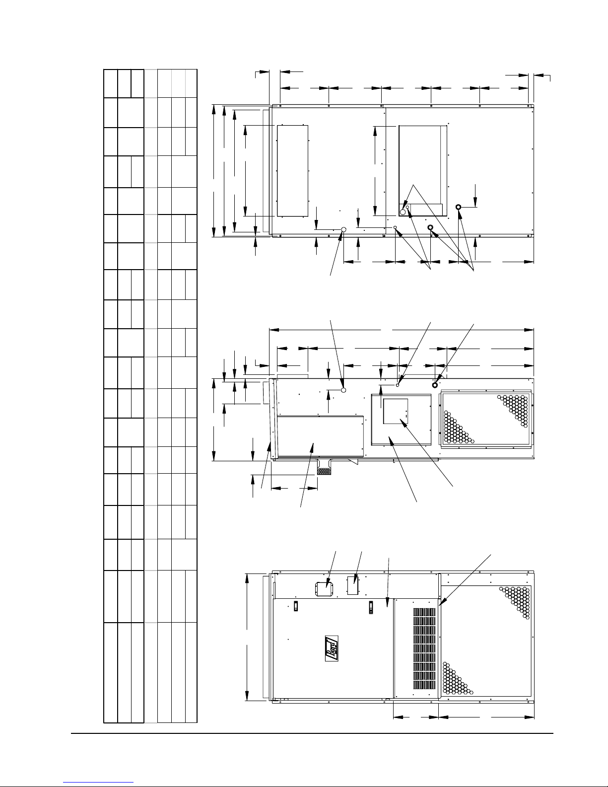
FIGURE 1
UNIT DIMENSIONS
II
Q
X
AA
Y
V
10
GAS
ENTRANCES
LOW VOLTAGE
ENTRANCES
HIGH VOLTAGE
ENTRANCES
H
12.19
FF
GG
HH
A
I
U
Z
M
C
L
KJ
DD
8.44
D
CONDENSER
17 .34
42
P
AIR OUTLETS
RIGHT SIDE BACK
N
2.88 22.9 38 17.84 4.44 11.44 9 36.25 2 0.38
3.88 24.
VESTIBULE
DOOR
4 DEG. PITCH IN TOP
COMBUSTION
AIR EXHAUST
COMBUSTION
AIR INTAKE
CONTROL
SERVICE/FILTER
PANEL DOOR
HINGED DOOR
VENT OPTION
PANEL
CIRCUIT BREAKER/
DISCONNECT ACCESS
PANEL (LOCKABLE)
UNIT A B C D E F G H I J K L M N O P Q R
WG241-WG301-WG361 7.88 27.88 13.88 24.25 40 25.63 81.63 27.38 27.5 39.25 5.88
Manual 2100-365K
Page 6
UNIT S T U V W X Y Z AA BB CC DD EE FF GG HH II
WG422-WG481-WG601 9.88 29.88 15.88 27.25 43.81 31.63 87.5 33.38 28.75 42.88 3.75
WG241-WG301-WG361 12 - 7 HOLE
WG422-WG481-WG601 16 - 6 HOLE
W
CONDENSER
AIR INLET
F
G
FRONT
WARNING
In all cases, there must be a metal duct
connection made to the supply air flange, and
a one inch clearance to combustibles must be
maintained to this duct connection.
For free blow applications, a metal sleeve
must be used in the wall opening itself, again
maintaining a one inch clearance to
combustibles.
Failure to use the sheet metal can cause
fire resulting in property damage, injury, or
death.
4. HIGH ALTITUDE APPLICATIONS
Ratings of gas utilization equipment are based on sea
level operation and need not be changed for operation
at elevations up to 6,000 feet. For operation at
elevations above 6,000 feet and in the absence of
specific recommendations from the local authority
having jurisdiction, equipment ratings shall be reduced
as specified in Section 21.
5. TRANSPORTATION DAMAGE
All units are packed securely in shipping container.
All units should be carefully inspected upon arrival for
damage. In the event of damage, the consignee should:
1. Note on delivery receipt of any damage to container.
See Figure 3 and clearance information in Section 9
and Table 2 for additional information.
Design the duct work according to methods given by
the Air Conditioning Contractors of America (ACCA).
When duct runs through unheated spaces, it should be
insulated with a minimum of one inch of insulation.
Use insulation with a vapor barrier on the outside of
the insulation. Flexible joints should be used to
connect the duct work to the equipment in order to
keep the noise transmission to a minimum.
A one inch clearance to combustible material for the
first three feet of duct attached to the outlet air frame is
required. See Wall Mounting Instructions and Figures
2, 2A and 3 for further details.
Ducts through the walls must be insulated and all joints
taped or sealed to prevent air or moisture entering the
wall cavity.
Some installations may not require any return air duct.
A metallic return air grille is required with installations
not requiring a return air duct. The spacing between
louvers on the grille shall not be larger than 5/8 inch.
Any grille that meets with the 5/8 inch louver criteria
may be used. It is recommended that Bard Return Air
Grille or Return Filter Grille be installed when no
return duct is used. Contact distributor or factory for
ordering information. If using a return air filter grille,
filters must be of sufficient size to allow a maximum
velocity of 400 fpm.
NOTE: If no return air duct is used, applicable
installation codes may limit this cabinet to
installation only in a single story structure.
2. Notify carrier promptly, and request an inspection.
3. In case of concealed damage, the carrier must be
notified as soon as possible within 15 days after
delivery.
4. Claims for any damage, apparent or concealed,
should be filed with the carrier, using the following
supporting documents:
A. Original Bill of Lading, certified copy, or
indemnity bond.
B. Original paid freight bill of indemnity in lieu
thereof.
C. Original invoice or certified copy thereof
showing trade and other discounts or
deductions.
D. Copy of the inspection report issued by
carrier’s representative at the time damage is
reported to carrier.
6. INSTALLATION
Size of unit for proposed installation should be based
on heat loss/heat gain calculations made according to
methods of Air Conditioning Contractors of America
(ACCA). The air duct should be installed in
accordance with the Standards of the National Fire
Protection Association for the Installation of Air
Conditioning and Ventilating Systems of Other Than
Residence Type, NFPA No. 90A, and Residence Type
Warm Air Heating and Air Conditioning Systems,
NFPA No. 90B. Where local regulations are at a
variance with instructions, installer should adhere to
local codes.
Manual 2100-365K
Page 7
7. WALL MOUNTING INFORMATION
1. Two holes for the supply and return air
openings must be cut through the wall as
detailed in Figure 4.
2. On wood-frame walls, the wall construction
must be strong and rigid enough to carry the
weight of the unit without transmitting any unit
vibration.
WARNING
Failure to provide the one inch clearance
between the supply duct and a combustible
surface for the first three feet of duct can
result in fire causing damage, injury or death.
3. Concrete block walls must be thoroughly
inspected to insure that they are capable of
carrying the weight of the installed unit.
8. MOUNTING THE UNIT
1. These units are secured by wall mounting
brackets which secure the unit to the outside
wall surface at both sides. A bottom mounting
bracket is provided for ease of installation but
is not required.
CAUTION
If the bottom bracket is used, be certain the
bracket is secured to the outside wall surface
in a way sufficient to support the entire weight
of the unit during installation until side
mounting brackets are secured.
2. The WG42, WG48 and WG60 models are
suitable for 0 inch clearance on the installation
mounting wall and to the top. For all models the
supply air duct flange and the first 3 feet of
supply air duct require a minimum of 1 inch
clearance to combustible material. The WG24,
WG30 and WG36 models are suitable for 0 inch
clearance on the installation mounting wall, but
require 1 inch clearance to the top if combustible
material overhang projects above the unit. See
Figure 3 and 3A. If a combustible wall, use a
minimum of Figure 1 “A” dimension plus 2
inches and “B” dimension plus 2 inches. See
Figures 4 and 5 for details.
3. Locate and mark lag bolt locations and bottom
mounting bracket location.
4. Mount bottom mounting bracket.
5. Hook top rain flashing under back bend of top.
Top rain flashing is shipped secured to the right
side of the back.
6. Position unit in opening and secure with 5/16
lag bolts; use 7/8 inch diameter flat washers on
the lag bolts. Use lag bolts long enough to
support the unit’s weight when mounted to the
structure. This length may be dependant on the
type of construction.
7. Secure rain flashing to wall and caulk across
entire length of top. See Figure 3.
8. On side by side installations, maintain a
minimum of 20 inches clearance on right side
to allow access to control panel and burner
compartment, and to allow proper airflow to the
outdoor coil. Additional clearance may be
required to meet local or national codes.
Manual 2100-365K
Page 8
RIGHT SIDE
VIEW WITH UNIT
1" MIN.
NECCESSARY
NO CLEARANCE
MIS-1681
MIS-1681
1" CLEARANCE ON ALL
FOUR SIDES OF SUPPLY
AIR DUCT IS REQUIRED FROM
RAIN FLASHING
SUPPLIED
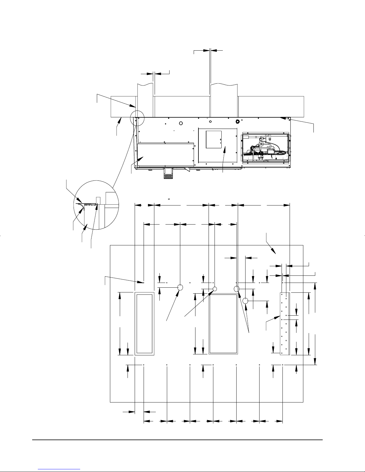
FIGURE 2
MOUNTING INSTRUCTIONS
FOR WG24, WG30, AND WG36
COMBUSTABLE MATERIALS
TOP
FOAM AIR SEAL
WALL
STRUCTURE
(OUTSIDE)
SUPPLY
VESTIBULE
DOOR
AIR DUCT
10"
18 15/16"
2 1/4"
28 5/16"
17 15/16"
2 15/16"
RETURN
AIR DUCT
CONTROL
PANEL
15"
11 5/16"
4 1/2"
27"
WALL
NOTE: IT IS RECOMMENDED THAT A BEAD
OF SILICONE CAULKING BE PLACED BEHIND
THE SIDE MOUNTING FLANGES AND UNDER
TOP FLASHING AT TIME OF INSTALLATION
2 1/4"
7/16"
SEAL WITH BEAD OF CAULKING
ALONG ENTIRE LENGTH OF TOP
(12) FLANGE
SCREWS
30"
UNIT REMOVED
OUTSIDE WALL WITH
4 9/16"
SUPPLY
AIR DUCT
4 9/16"
Ø2 3/4" GAS
OPENING
(OPTIONAL)
12"
29"
5 1/16"
Ø2" LOW VOLTAGE
(OPTIONAL)
12"
12"
RETURN
AIR DUCT
12"
2 15/16"
Ø2 3/4" HIGH
VOLTAGE
(OPTIONAL)
12"
8 5/8"
5 9/16"
UNIT SUPPORT
12"
Manual 2100-365K
Page 9
2"
4 11/16"
29 3/4"
39 3/16"
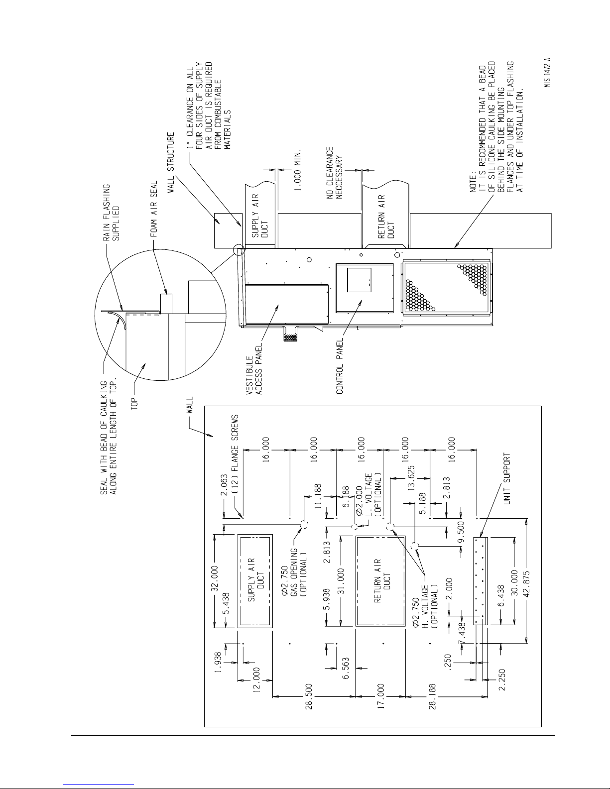
FIGURE 2A
MOUNTING INSTRUCTIONS
FOR WG42, WG48, AND WG60
Manual 2100-365K
Page 10
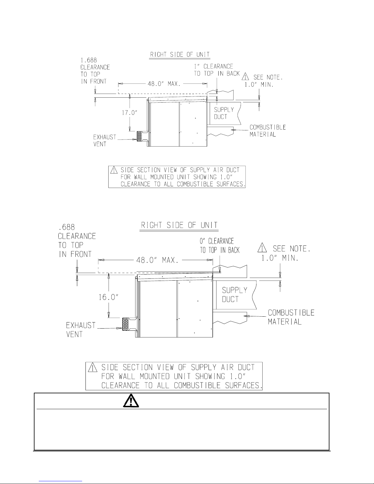
FIGURE 3
COMBUSTIBLE CLEARANCE
FOR WG24, WG30 AND WG36 MODELS
FIGURE 3A
COMBUSTIBLE CLEARANCE
FOR WG42, WG48 AND WG60 MODELS
MIS-1682
A minimum of one (1) inch clearance must be maintained between the supply air duct and combustible materials.
This is required for the first three (3) feet of ducting.
It is important to insure that the one (1) inch minimum spacing is maintained at all points.
Failure to do this could result in overheating the combustible material and may result in a fire causing damage,
injury or death.
MIS-1714
WARNING
Manual 2100-365K
Page 11
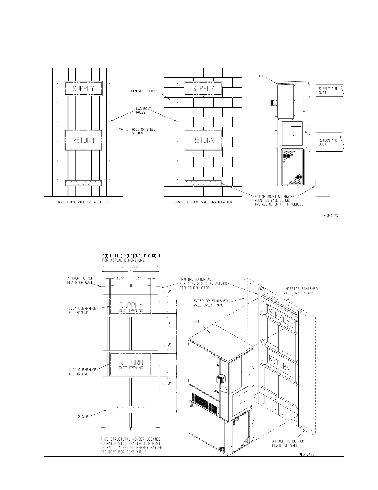
FIGURE 4
WALL MOUNTING INSTRUCTIONS
FIGURE 5
WALL MOUNTING INSTRUCTIONS
Manual 2100-365K
Page 12
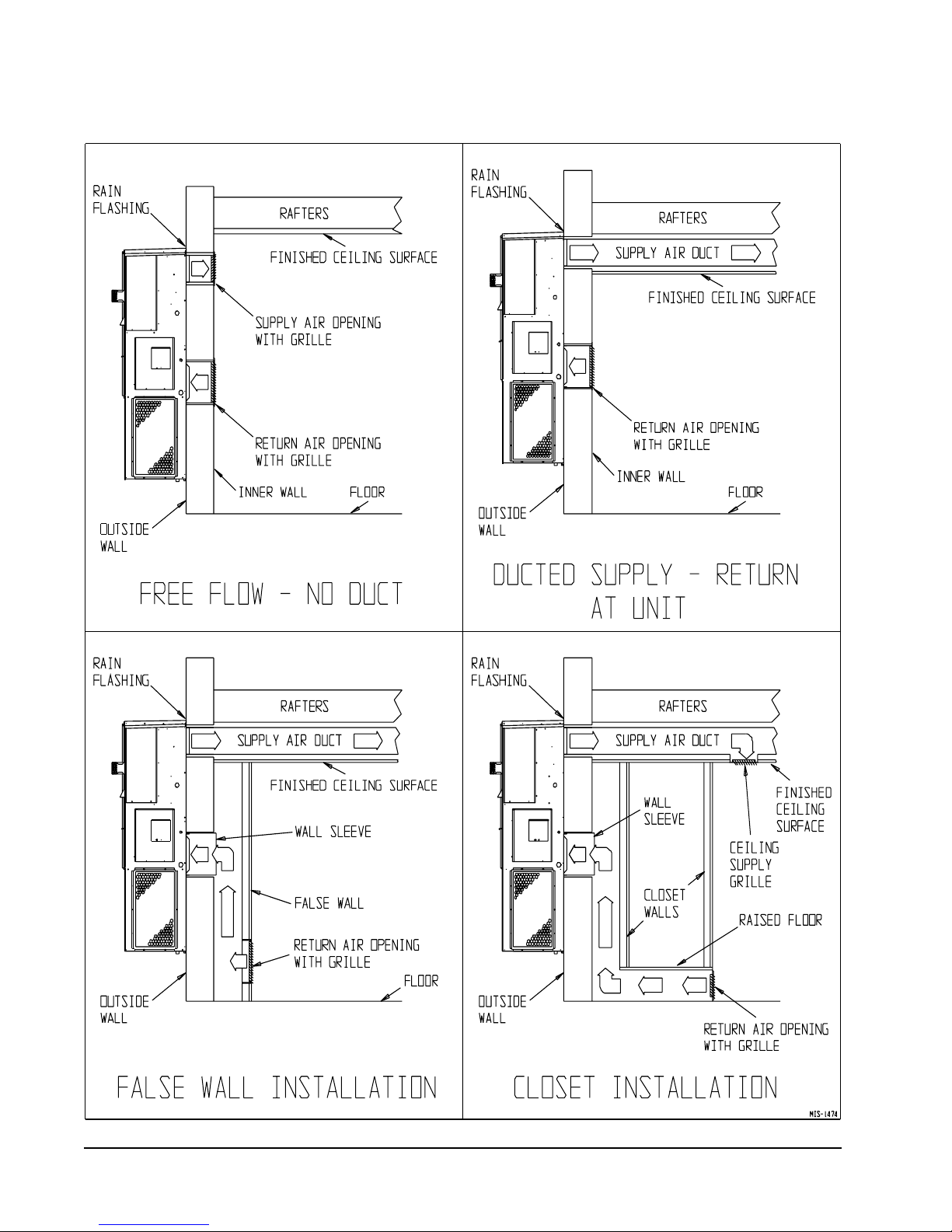
FIGURE 6
COMMON WALL MOUNTING INSTALLATIONS
Manual 2100-365K
Page 13
9. CLEARANCES
Minimum clearances, as specified in Table 2, must be
maintained from adjacent structures to provide
adequate fire protection, adequate combustion air, and
room for service personnel.
While minimum clearances are acceptable for safety
reasons, they may not allow adequate air circulation
around the unit for proper operation in the cooling
mode. Whenever possible, it is desirable to allow
additional clearance, especially around the condenser
inlet and discharge openings. DO NOT install the unit
in a location that will permit discharged air from the
condenser to recirculate to the condenser inlet.
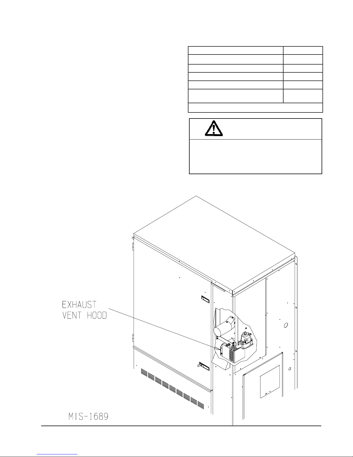
LOCATION OF VENT TERMINAL IN SHIPPING
FIGURE 7
TABLE 2
MINIMUM INSTALLATION CLEARANCES
)slairetamelbitsubmocmorf(tcuDteltuOteef3tsrifhcni1
)slairetamelbitsubmocmorf(lanimreTtneV
*
teltuOresnednoCsehcni02
poT3erugiFeeS
ecivreSrenruBsehcni02
)lairetamgnirevocfoorCro
*
B,AssalCrodooW(esaBelbitsubmoC
A3dna3serugiFeeS
WARNING
Clearances from combustible materials must
be maintained as specified. Failure to
maintain clearances could cause fire resulting
in property damage, injury, or death.
sehcni71
sehcni0
Manual 2100-365K
Page 14
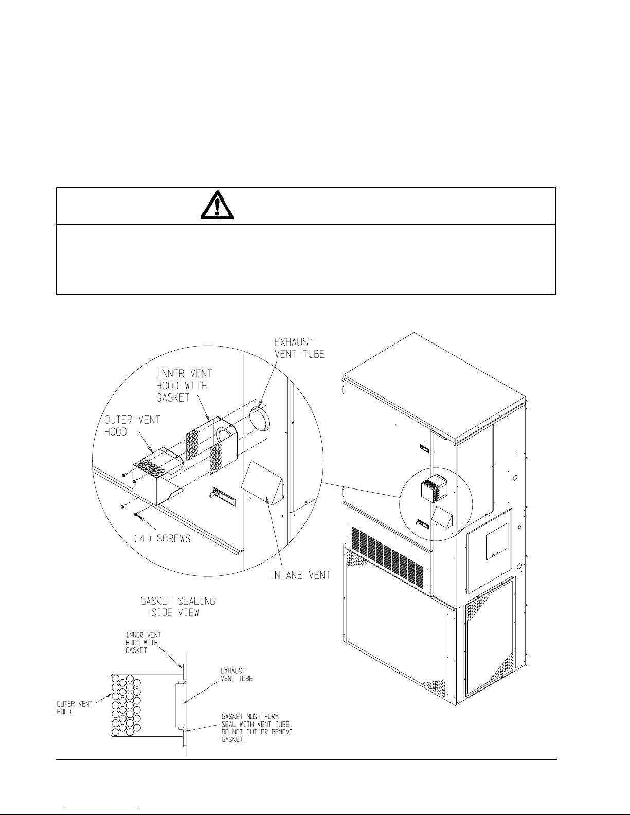
10. VENT TERMINAL AND COMBUSTION
AIR INLET HOOD
The vent terminal is shipped in the burner
compartment. See Figure 7. Remove the two shipping
screws and separate the two-piece assembly. Install the
vent terminal by using the four screws provided. Make
sure gasket is in place. See Figure 8. The combustion
air intake hood is factory installed.
11. OPTIONAL VERTICAL VENTING
With the optional vertical venting kit (VVK-5) this unit
may be vented vertically through a roof or overhang.
The kit includes a stainless steel transition drain tee,
silicone sealant, and drain tubing.
If unit is installed with vertical vent kit, annually
inspect the vent system and drain. Replace any portion
of the vent system that shows signs of deterioration.
Make sure drain is open and free of obstruction.
CAUTION
Vent terminal must be installed as shown in Figure 8 for proper operation of the heating system.
NOTE: The inner vent hood gasket is designed to stretch over and seal around the combustion
air blower outlet. This is a very critical seal to prevent water and flue products from entering the
unit. Care must be taken to ensure this gasket is in place and sealing properly.
FIGURE 8
VENT TERMINAL AND COMBUSTION AIR INTAKE
MIS-1469
MIS-2057
Manual 2100-365K
Page 15
12. VENT RESIZING INSTRUCTIONS
When an existing furnace is removed from a venting
system servicing other appliances, the venting system is
likely to be too large to properly vent the remaining
attached appliances.
The following steps shall be followed with each of the
appliances remaining connected to the common venting
system, placed in operation one at a time while the
other appliances remaining connected to the common
venting system are not in operation.
1. Seal any unused openings in the venting system.
2. Inspect the venting system for proper size and
horizontal pitch, as required in the National Fuel Gas
code, ANSI Z223.1 or the CAN/CGA B149
Installation Codes and these instructions. Determine
that there is no blockage or restriction, leakage,
corrosion and other deficiencies which could cause
an unsafe condition.
3. In so far as is practical, close all building doors and
windows and all doors between the space in which
the appliance(s) connected to the venting system are
located and other spaces of the building. Turn on
clothes dryers and any appliances not connected to
the venting system. Turn on any exhaust fans, such
as range hoods and bathroom exhausts, so they will
operate at maximum speed. Do not operate a
summer exhaust fan. Close fireplace dampers.
4. Follow the lighting instructions. Place the appliance
being inspected in operation. Adjust thermostat so
appliance shall operate continuously.
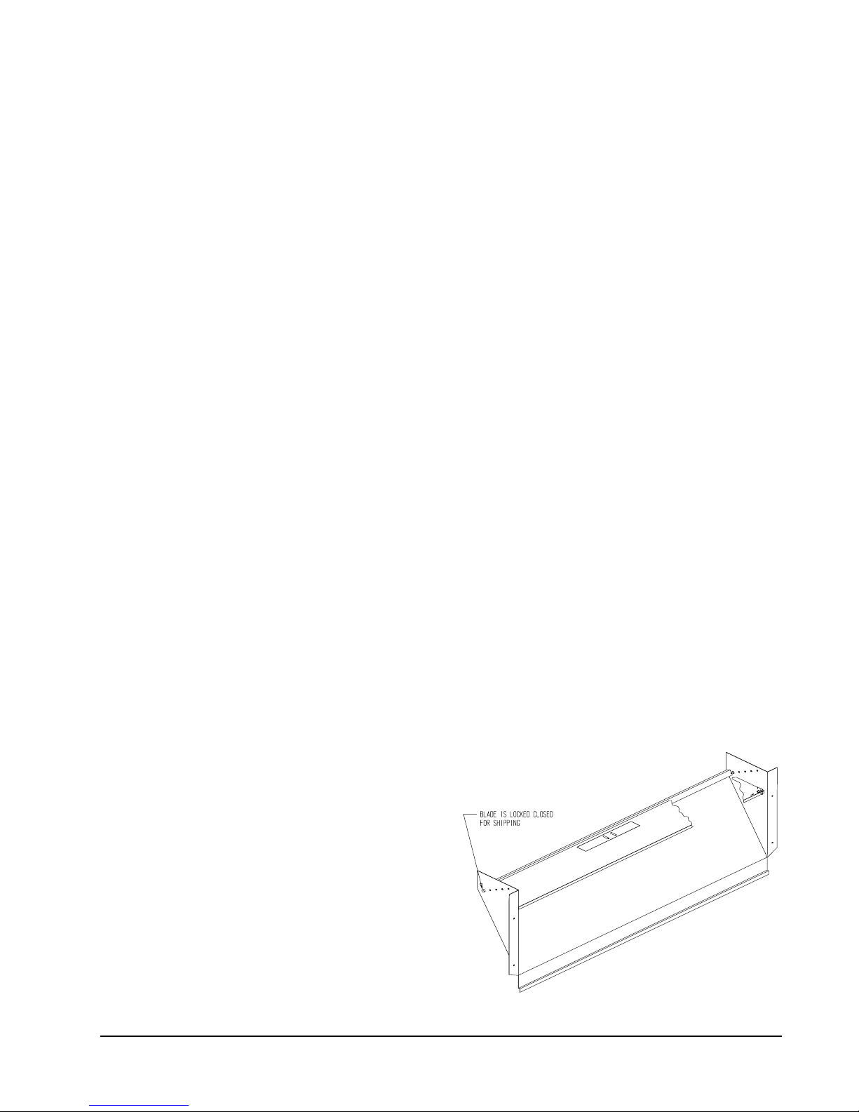
13. FRESH AIR INTAKE
All units are built with fresh air inlet slots punched in
the service panel.
If the unit is equipped with a fresh air damper
assembly, the assembly is shipped already attached to
the unit. The damper blade is locked in the closed
position. To allow the damper to operate, the
maximum and minimum blade position stops must be
installed. See Figure 9.
All capacity, efficiency and cost of operation
information as required for Department of Energy
“Energyguide” Fact Sheets is based upon the fresh air
blank-off plate in place and is recommended for
maximum energy efficiency.
The blank-off plate is available upon request from the
factory and is installed in place of the fresh air damper
shipped with each unit.
One of several other ventilation options may be
installed. Refer to model number and/or supplemental
installation instructions.
14. CONDENSATE DRAIN
A plastic drain hose extends from the drain pan at the
top of the unit down to the unit base. There are
openings in the unit base for the drain hose to pass
through. In the event the drain hose is connected to a
drain system of some type, it must be an open or vented
type system to assure proper drainage.
5. Test for draft hood equipped appliance spillage at the
draft hood relief opening after 5 minutes of main
burner operation. Use the flame of a match or
candle.
6. After it has been determined that each appliance
connected to the venting system properly vents when
tested as outlined above, return doors, windows,
exhaust fans, fireplace dampers and any other gasburning appliances to their previous conditions of
use.
7. If improper venting is observed during any of the
above tests, the venting system must be corrected.
FIGURE 9
FRESH AIR DAMPER
MIS-938
Manual 2100-365K
Page 16
15. WIRING – MAIN POWER
WARNING
For your personal safety, turn off electric
power at service entrance panel before
making any electrical connections. Failure to
do so could result in electric shock or fire.
Refer to unit rating plate for wire sizing information
and maximum fuse or “HACR” type circuit breaker
size. Each outdoor unit is marked with a “Minimum
Circuit Ampacity”. This means that the field wiring
used must be sized to carry that amount of current. All
models are suitable only for connection with copper
wire. Each unit and/or wiring diagram will be marked “Use Copper Conductors Only”. These instructions
must be adhered to. Refer to the National Electrical
Code (NEC) for complete current carrying capacity
data on the various insulation grades of wiring material.
All wiring must conform to NEC and all local codes.
The electrical data lists fuse and wire sizes (75° C
copper) for all models.
ELECTRICAL GROUNDING
When installed, the furnace must be electrically
grounded in accordance with local codes or in the
absence of local codes, with the National Electrical
Code, ANSI/NFPA 70, or Canadian Electrical Code,
CSA22.1, latest edition. Use a copper wire from green
ground wire on the furnace to a grounded connection in
the service panel or a properly driven and electrically
grounded ground rod. See Table 1 for proper ground
wire size.
WARNING
Failure to provide a proper electrical ground
could result in electric shock or fire.
FIELD INSTALLED EQUIPMENT
Wiring to be done in the field between the furnace and
devices not attached to the furnace, or between separate
devises which are field installed and located, shall
conform with the temperature limitation for Type T
wire {63 degrees F rise (36 degrees C)} when installed
in accordance with the manufacturer’s instructions.
The unit rating plate lists a “Maximum Time Delay
Relay Fuse” or “HACR” type circuit breaker that is to
be used with the equipment. The correct size must be
used for proper circuit protection and also to assure that
there will be no nuisance tripping due to the momentary
high starting current of the compressor motor.
The disconnect access door on this unit may be locked
to prevent unauthorized access to the disconnect. To
convert for the locking capability bend the tab located
in the bottom left hand corner of the disconnect opening
under the disconnect access panel straight out. This tab
will now line up with the slot in the door. When shut a
padlock may be placed through the hole in the tab
preventing entry.
See “Start Up” section for important information on
three phase scroll compressor start ups.
WARNING
Failure to provide an electrical power supply
shut off means could result in electric shock
or fire.
INSTALLATION OF FLEXIBLE CONDUIT
THROUGH RETURN AIR OPENING
NOTE: To allow proper clearance between the
control panel and any vent options, 90°
conduit fittings must be used on the back of
the control panel.
INSTALLING CONDUIT (See Figure 10.)
1. Remove conduit access panel if required to gain
access to area behind control panel.
2. Remove low voltage and high voltage knockouts
located in rear of control panel.
3. Run low voltage conduit through 7/8 bushing located
in conduit entrance plate and secure to low voltage
opening in rear of control panel.
4. Run high voltage conduit through 1-3/4 bushing
located in conduit entrance plate and secure to high
voltage opening in rear of control panel.
5. Replace conduit access panel if required to complete
installation.
6. Seal around conduit in conduit entrance plate.
Manual 2100-365K
Page 17
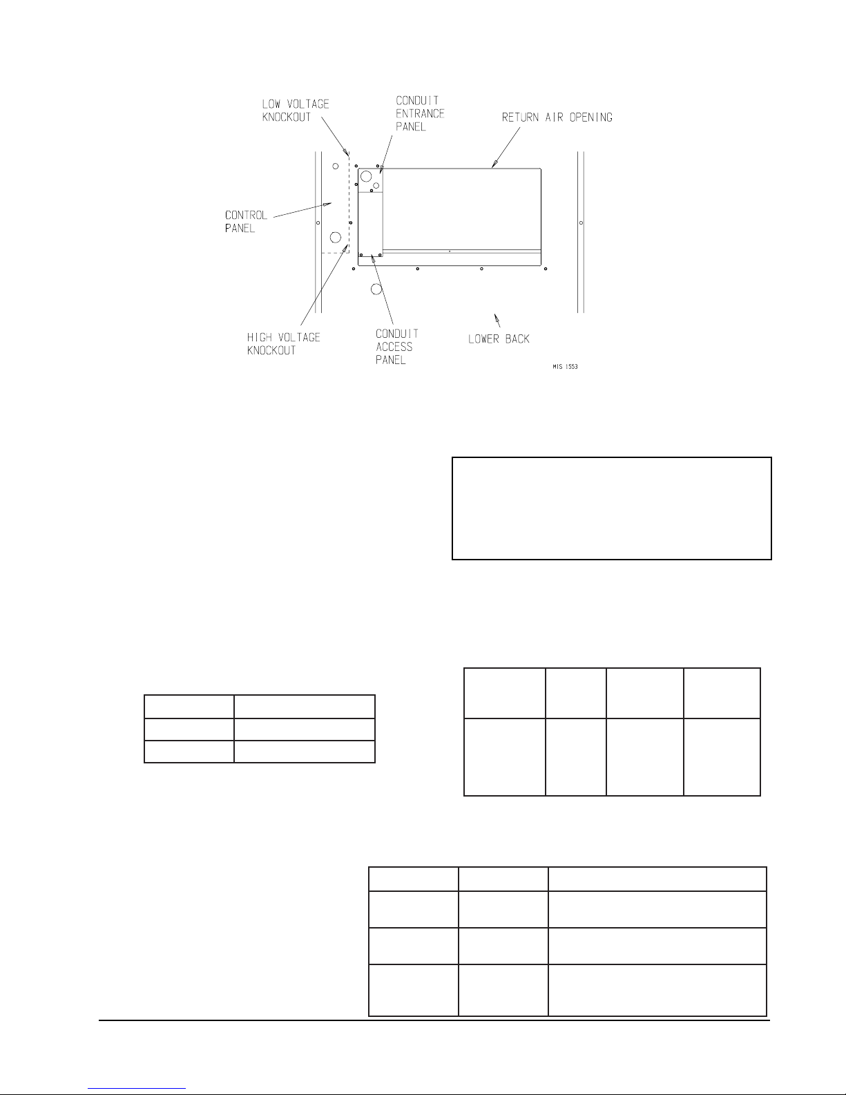
FIGURE 10
INSTALLATION OF FLEXIBLE CONDUIT
16. WIRING – LOW VOLTAGE WIRING
Low Voltage Connection
These units use a 24-volt AC low voltage circuit.
The “R” terminal is the hot terminal and the “C”
terminal is grounded.
“G” terminal is the fan input.
“Y” terminal is the compressor input.
“R” terminal is 24 VAC hot.
“C” terminal is 24 VAC grounded.
“E” terminal is the ventilation input. This terminal
energizes any factory or field installed vent option.
230/208 VOLT UNITS
All models are equipped with dual primary voltage
transformers. All equipment leaves the factory wired
on 240V tap. For 208V operation, reconnect from
240V to 208V tap. The acceptable operating voltage
range for the 240V and 208V taps are:
PATEGNAR
042612--352
802781--022
NOTE: The voltage should be measured at the field
power connection point in the unit and while
the unit is operating at full load (maximum
amperage operating condition).
460 VOLT UNITS
All models are equipped with single
primary voltage transformers and no
rewiring is required.
Direct Digital Controls (DDC)
For total and proper control using DDC, a total of 5
controlled outputs are required (4 if no ventilation is
installed).
LOW VOLTAGE CONNECTIONS FOR DDC CONTROL
Fan Only Energize G
Cooling Mode Energize G, Y
Heating Mode Energize W1
Ventilation Energize G, E
17. THERMOSTATS
TABLE 3
THERMOSTAT WIRE SIZE
remrofsnarT
AVALFeguaGeriW
553.2eguag02
eguag81
eguag61
eguag41
eguag21
TABLE 4
WALL THERMOSTAT AND SUBBASE COMBINATIONS
tatsomrehTesabbuSserutaeFetanimoderP
200-3048
1113F78T
0-3048
94
083-39F1
840-3048
3131C0048T
300-4048
0221A935Q
---
---
54
06
001
061
052
loocegats2,taehegats2
elbammargorPcinortcelE
loocegats1,taehegats1
elbammargorP-noNcinortcelE
mumixaM
ecnatsiD
teeFnI
yrucreM;loocegats1,taehegats1
otua-no:naFlooc-ffo-taeh:metsyS
otua-no:naFlooc-ffo-taeh:metsyS
Manual 2100-365K
Page 18
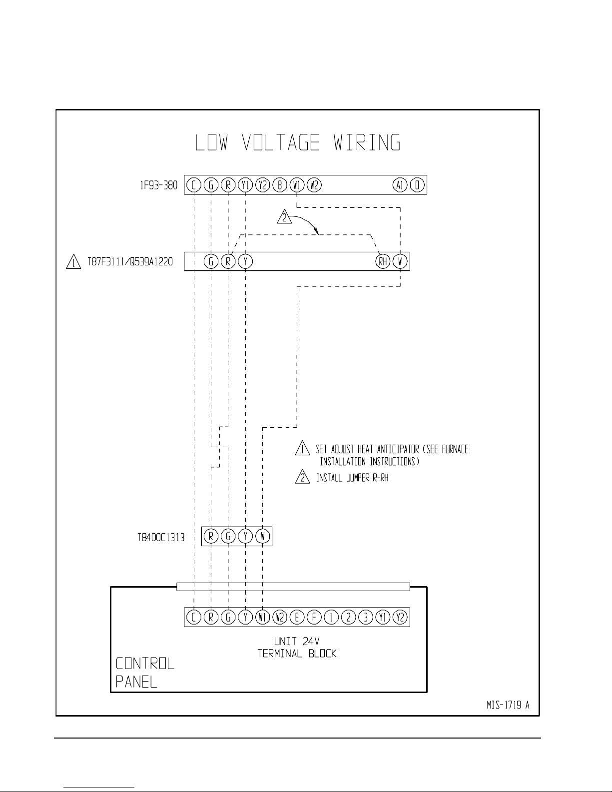
FIGURE 11
LOW VOLTAGE WIRING
Manual 2100-365K
Page 19
 Loading...