

Bard WFERV-A-X, WFERV-A-4 Installation Instructions Manual

INSTALLATION INSTRUCTIONS
ENERGY RECOVERY VENTILATOR
WITH EXHAUST
MODELS:
WFERV-A-X
WFERV-A-4
Bard Manufacturing Company, Inc.
Bryan, Ohio 43506
Since 1914...Moving ahead, just as planned.
Manual: 2100-495A
Supersedes: 2100-495
File: Volume III, Tab 19
Date: 04-02-08
Manual 2100-495A
Page 1 of 21

CONTENTS
Model Nomenclature Legend..................................... 3
Electrical Specifications............................................. 3
General Description ................................................... 3
General Information ................................................... 3
Unpacking .................................................................. 3
Performance and Application Data - WFERV............ 4
Basic Installation (Field Installation)................... 5 & 6
Basic Installation (Factory Installed Versions)......... 15
Figures
Figure 1 Intake Hood Assembly ............................ 6
Figure 2 Remove Vent Option Door...................... 7
Figure 2A Assembly of Exhaust Blower Enclosure ... 7
Figure 3 Filter & Exhaust Plate Location .............. 8
Control Wiring.......................................................... 15
Control Requirements.............................................. 15
Recommended Control Sequences......................... 15
Ventilation Airflow .................................................... 15
Energy Recovery Ventilator Maintenance ............... 16
Maintenance Procedures......................................... 16
Quarterly & Annual Maintenance............................. 17
Wiring Diagram ........................................................ 21
Tables
Table 1 Ventilation Air (CFM)................................ 16
Figure 4
Figure 5 Installation of WFERV........................... 10
Figure 6 WFERV Assembly..................................11
Figure 7 Wiring - 230 Volt ................................... 12
Figure 8 Installation of Fresh Air Intake
Figure 9 Operation of Unit with WFERV ............. 14
Figure 10 Thermostat Wiring ................................ 18
Figure 11 Terminal Block Location Diagram ......... 19
Figure 12 Hub Assembly with Ball Bearings ......... 20
Installation of Exhaust Blower Assembly ...
Hood Assembly ..................................... 13
BARD MANUFACTURING COMPANY , INC.
BRYAN, OHIO USA 43506
9
Manual 2100-495A
Page 2 of 21
MODEL NOMENCLATURE LEGEND
WF = Wall Mount Gas Furnace
WF ERV – X
Energy Recovery Ventilator
ELECTRICAL SPECIFICATIONS
lortnoC
ledoMegatloVspmA
VREFW802/0321.2V42
egatloV
GENERAL DESCRIPTION
The Energy Recovery Ventilator was designed to
provide energy efficient, cost effective ventilation to
meet I.A.Q. (Indoor Air Quality) requirements while still
maintaining good indoor comfort and humidity control
for a variety of applications such as schools, classrooms,
lounges, conference rooms, beauty salons and others. It
provides a constant supply of fresh air for control of
airborne pollutants including CO2, smoke, radon,
formaldehyde, excess moisture, virus and bacteria.
The ventilator incorporates patented rotary heat
exchanger technology to remove both heat and moisture.
It is designed as a single package, which can be easily
factory or field installed for new installations or retrofit to
Bard WF wall mounted units. The package consists of a
unique rotary Energy Recovery Cassette that can be easily
removed for cleaning or maintenance. The cassette has a
21-inch diameter heat transfer wheel for efficient heat
transfer. The heat transfer wheel uses a permanently
bonded dry desiccant coating for total heat recovery.
Ventilation is accomplished with two (2) blower/motor
assemblies each consisting of a drive motor and dual
blowers for maximum ventilation at low sound levels.
On non-independent motor control models, the air is
exhausted at the same rate that fresh air is brought into
the structure, thus not impacting building pressure. On
independent motor control models, the air can be
exhausted at a different rate than the intake or fresh air.
Never operate the fresh air at a lower speed than the
exhaust air. Operating the fresh air at a higher speed
than the exhaust air will help maintain a slight positive
pressure in the building. The rotating energy wheel
provides the heat transfer effectively during both
summer and winter conditions. Provides required
ventilation to meet the requirements of ASHRAE 62.12007 standard.
Color
-X = Beige
-4 = Buckeye Gray
NOTE: Never set intake blower at a lower speed than
the exhaust blower, as it will create a
negative pressure in the room.
During operation below 5 degrees F outdoor
temperature, freezing of moisture in the heat
transfer wheel can occur. Consult the factory
if this possibility exists.
GENERAL INFORMATION
The ventilator should only be installed by a trained
heating and air conditioning technician. These
instructions serve as a guide to the technician installing
the ventilator package. They are not intended as a stepby-step procedure with which the mechanically-inclined
owner can install the package.
The ventilator housing is shipped in one carton, which
contains the following:
1. Energy Recovery Ventilator
2. Service Door
3. Rain Hood and Mist Eliminator
4. Installation Instructions
UNPACKING
Upon receipt of the equipment, be sure to compare the
model number found on the shipping label with the
accessory identification information on the ordering and
shipping document to verify that the correct accessory
has been shipped.
Inspect the carton housing of each ventilator as it is
received, and before signing the freight bill, verify that
all items have been received and that there is no visible
damage. Note any shortages or damage on all copies of
the freight bill. The receiving party must contact the last
carrier immediately, preferably in writing, requesting
inspection by the carrier’s agent. Concealed damage not
discovered until after loading must be reported to the
carrier within 15 days of its receipt.
Manual 2100-495A
Page 3 of 21
tneibmA
.D.O
/BD
BWF
5015707
56
08
57
001
07
56
06
08
57
07
59
56
06
08
57
07
09
56
06
08
57
07
58
56
06
57
07
08
56
06
07
57
56
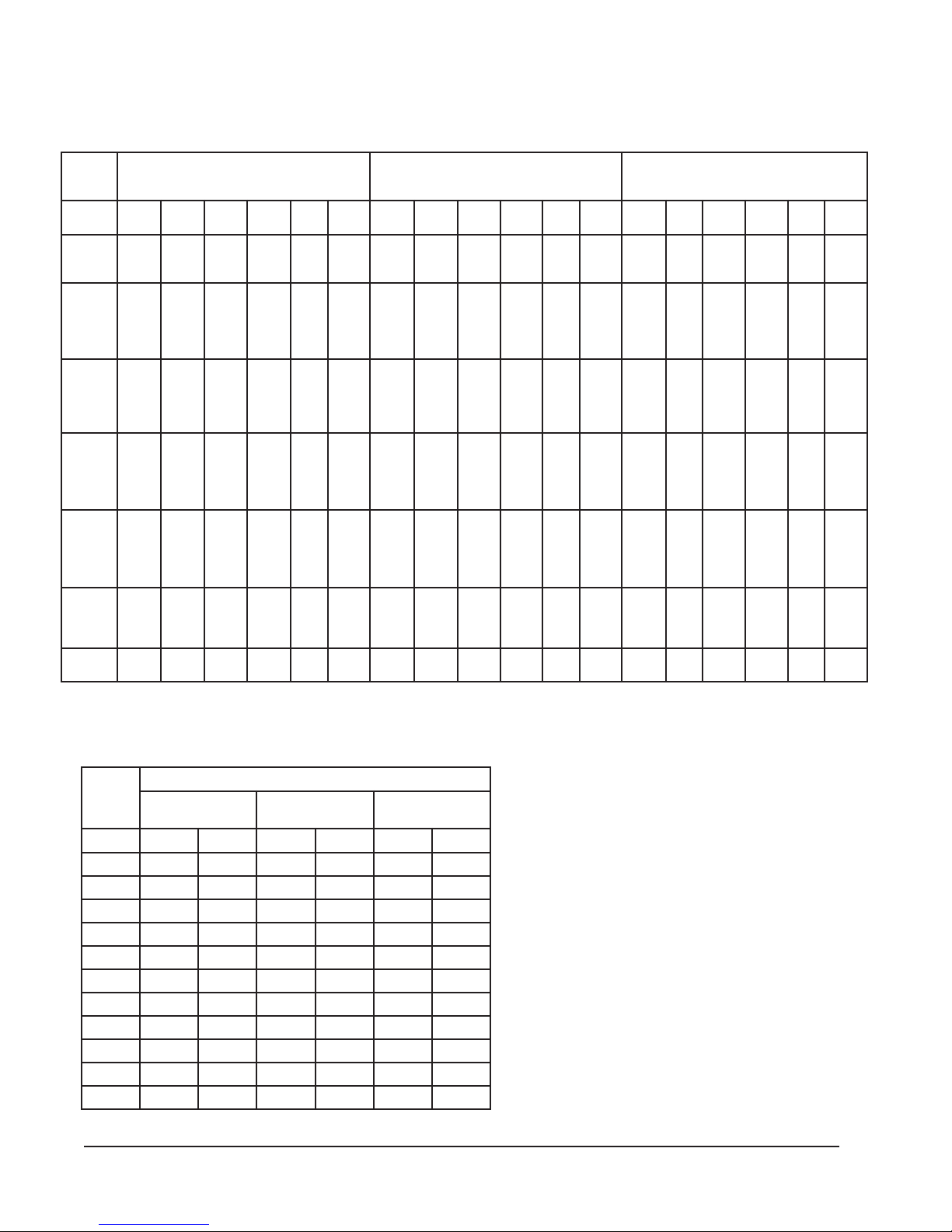
APPLICATION DATA — WFERV
SUMMER COOLING PERFORMANCE
(INDOOR DESIGN CONDITIONS 75°DB/63°WB)
MFC054—ETARNOITALITNEV
)kcalB(deepShgiH
YCNEICIFFE%27
TLVSLVLLVTRHSRHLRHTLVSLVLLVTRHSRHLRHTLVSLVLLVTRHSRHLRH
00471
00821
00821
00821
00821
00701
00662
00701
00571
00701
00701
00701
00701
00701
00701
0068
00862
0068
00771
0068
0069
0068
0068
0068
0068
004
00862
6
00771
0046
0069
0046
0046
0046
0046
0046
0034
00172
0034
00971
0034
0079
0034
0034
0034
0034
0012
0081
0089
0052
0012
00001
0062
51
0012
0012
0012
0
0
0029
0
0029
0
00191
00951
00621
0086
0077
0
0
0
00281
0019
21
0001
0
0
00402
00311
0023
0
0
00822
00631
0045
0
0
009
0077
004
0
00001
0062
077
0077
0077
00391
007
0096
0026
0026
00381
00721
0096
0064
0064
00591
013
00921
0096
0013
0013
00031
0007
0081
0051
0027
0
0091
0
0
0029
0
0029
0077
00411
0077
0094
0
0
0
0077
0
0077
00131
0026
0056
0026
007
0026
0
0026
0
0026
00741
0064
0018
0064
0032
0064
0064
0064
0
0013
0013
0013
0013
0051
0051
0051
0051
8
0
0
00461
0089
0083
0
0
00511
0055
0003
0
0027
0091
00211
00211
0
00211
0211
0049
00432
0049
00451
0049
0049
0049
0049
0049
0049
0057
00432
0057
00551
0057
0048
0057
0057
0057
0057
00532
0065
00651
0065
004
0065
0065
0065
0065
0065
0083
00832
0083
00851
0083
0068
0083
0083
0083
0083
0091
00851
0091
0078
0091
0032
0091
0088
0042
4
0091
0
0
00211
00251
0033
0029
00521
0064
00821
00111
0004
0028
0
0028
0
00171
00041
00211
0006
0096
0
0096
0
0096
0
00951
00171
0008
00211
009
0016
0055
0
0055
0
00271
00971
00411
00001
0016
0082
0014
0
0014
0
00471
00002
00511
00021
0
0084
036
0
0082
0
0082
00931
00511
0086
0036
00
0071
0041
0
0088
0046
0042
0571
MFC073—ETARNOITALITNEV
)eulB(deepSmuideM
YCNEICIFFE%37
0019
00421
0092
0028
0
0028
0
0028
0096
00201
00
96
0
0
0034
0
0096
0
0096
0
0096
00611
0055
0075
0055
006
0055
0
0055
0
0055
00131
0014
0037
0014
0002
0014
0
0014
0
0014
00641
0082
0078
0082
0053
0082
0
0082
0
0082
00101
0041
0094
0041
003
0041
0
0041
0046
0571
0019
0019
0019
0019
0067
00981
0067
00421
0067
0067
0067
0067
0067
0067
0016
00091
00521
0086
0016
0016
0
0191
00721
0096
0064
0064
00291
00721
0096
0003
0003
00821
0007
0081
0051
0017
0091
921
0016
0016
0016
0016
0064
0064
0064
0064
0064
0003
0003
0003
0003
0003
0051
0051
0051
0051
0
0
0033
0
0
00311
0084
0
0
0
00
0046
007
0
0
00541
0018
0032
0
0
00261
0079
0093
0
0
00311
0055
003
0
0017
0091
—ETARNOITALITNEV 082 MFC
0029
0076
0076
00041
0029
0065
0065
0065
00041
0029
0005
0054
0054
00141
0049
0015
0043
0043
00241
0049
0015
0022
0022
0059
002
5
0031
0011
0025
0041
)deR(deepSwoL
YCNEICIFFE%47
0076
0076
0076
0065
0065
0065
0065
0065
0054
0054
0054
0054
0054
0043
0043
0043
0043
0043
0022
0022
0022
0022
0022
0011
0011
0011
0011
0
0
0052
0
0
0048
0063
0
0
0
0059
0074
005
0
0
00701
0006
0071
0
0
00021
0027
0092
0
0
0048
0014
002
0
0025
0041
WINTER HEATING PERFORMANCE
(INDOOR DESIGN CONDITIONS 70° F DB)
ETARNOITALITNEV
tneibmA
.D.O
MFC054
.FFE%67
MFC073
.FFE%87
MFC082
.FFE%08
F°BDLVWRHWLVWRHWLVWRHW
56009402730043056200420291
06004606840094028300930213
55009700060046099400450234
05004905170097061600960255
540081107980099027700580086
040014101701008110029003010428
5300371051310053103501002110698
03009810634100751052210073106901
52002120116100771008310045102321
02006320497100791073510017108631
51009520869100712039610088104051
NOTE: Sensible performance only is shown for winter application
Manual 2100-495A
Page 4 of 21
LEGEND:
VLT = Ventilation Load – Total
VLS = Ventilation Load – Sensible
VLL = Ventilation Load – Latent
HRT = Heat Recover – Total
HRS = Heat Recovery – Sensible
HRL = Heat Recovery – Latent
WVL = Winter Ventilation Load
WHR = Winter Heat Recovery
BASIC INSTALLATION (Field Installation)
1. Unpack the ventilator assembly, which includes the
integral ventilator with attached electrical harness
and miscellaneous hardware.
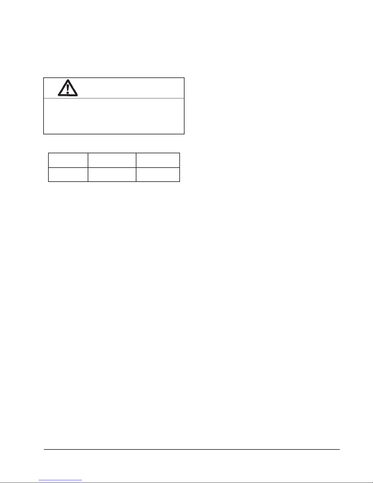
WARNING
Open breaker switch before installing this
accessory to prevent injury or death due to
electrical shock or contact with moving parts.
Turn thermostat to OFF.
htiWesUroF
ledoM
VREFW521-050FW
2. Remove intake hood assembly from back of
ventilator. (See Figure 1.)
3. Remove the existing exterior vent option door on
the unit. (See Figure 2.)
4. Remove and save existing unit air filter. Remove
and discard the rear exhaust cover plate. (See
Figure 3.)
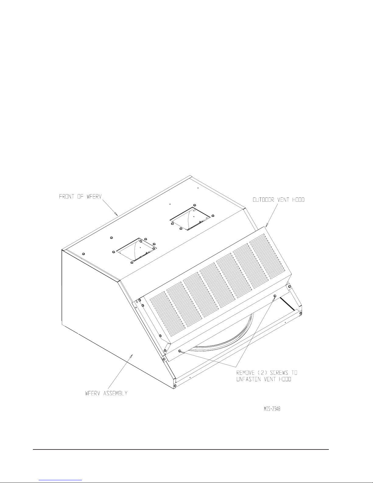
5. Install exhaust blower assembly in rear exhaust
opening and secure with four (4) screws. Position 4
pin connector so it is accessible. (See Figure 4.)
Assemble exhaust blower enclosure as shown in
Figure 2A. Fasten exhaust blower enclosure to
bottom of unit as shown in Figure 4.
6. Install ventilator into the unit. (See Figure 5.)
IMPORTANT NOTE: Position front lip of ventilator
over front grille and on top of condenser partition.
(See Figure 5.) This is important to insure proper
stinUgniwolloFlacirtcelE
1-802/032
esahp3ro
drainage of any water entering damper assembly.
7. Remove cassette and plug in exhaust blower.
Replace cassette. (See Figure 6.)
8. Open control panel to gain access to unit low
voltage terminal block. (Insure all power is OFF
prior to opening the control panel.)
9. Remove female plug of low voltage wiring harness
from the heat recovery assembly and snap into filter
rack. Route electrical harness leads through the
bushing into the low voltage box. (See Figure 5.)
10. Connect leads C (black), W (blue), and G (orange)
with fork terminal to corresponding points on
terminal strip. (See Figure 7 for 230V units.)
NOTE: These 24 volt control wires control the
starting and stopping of the Energy Recovery
Ventilator and can be independently controlled
by an energy management control or timer.
See separate section on Control Wiring for
suggested control schemes.
11. Remove female plug of high voltage wiring harness
from the heat recover assembly and snap into filter
rack. Wire to terminal block. (See Figure 7 for
230V units.)
12. Plug male plug from female at filter rack.
(See Figure 5.)
13. Close control panel cover.
14. Replace filter and one (1) screw in condenser grille.
(See Figure 3)
15. Ventilator checkout
A. Resupply power to unit.
B. Energize the evaporator blower by
switching thermostat to the manual fan
position with Heat/Cool in OFF position.
C. Ventilator heat transfer wheels should
rotate slowly (49 RPM). Intake and
exhaust blowers should run.
(See Figure 9.)
D. De-energize the evaporator blower.
Energy Recovery wheels, and fresh air
and exhaust air blowers should stop.
E. This completes ventilator checkout.
7/8"
Manual 2100-495A
Page 5 of 21
16. Disconnect the wires connected in Step 10 if other
control options are to be used.
17. Replace the lower service access panel with the
new panel provided. Attach air intake hood with
screws provided. (See Figure 9.) Be sure to insert
the top flange of the air intake hood into and
through the slot in the service door and between the
door and insulation to prevent bowing of the door.
INTAKE HOOD ASSEMBLY
18. Close front door.
19. Apply Certification label, included with Installation
Instructions, next to unit Serial Plate.
20. Assemble exhaust blower enclosure as shown in
Figure 2A and install on unit as shown in Figure 4
(with screws provided).
21. Ventilator is now ready for operation.
FIGURE 1
Manual 2100-495A
Page 6 of 21
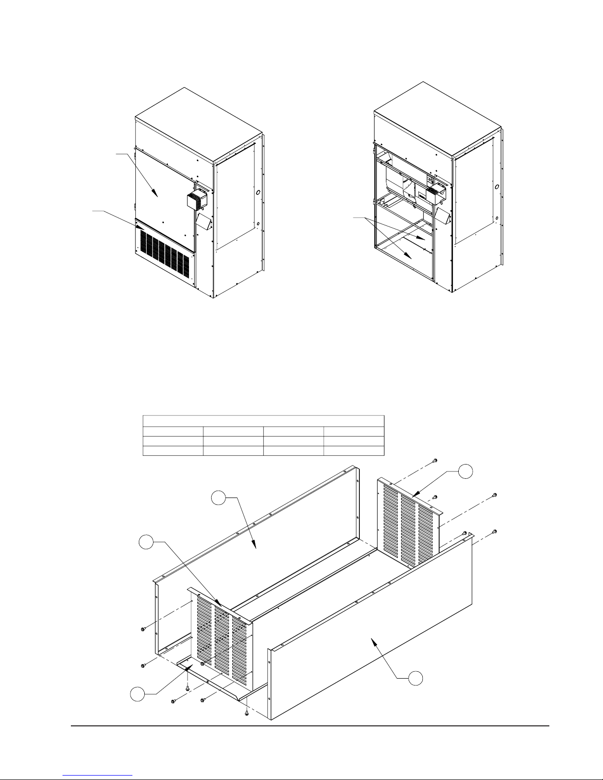
FRONT DOOR
VENT
OPTION
DOOR
FIGURE 2
REMOVE VENT OPTION DOOR
EXHAUST
COVER PLATES
FIGURE 2A
ASSEMBLY OF EXHAUST BLOWER ENCLOSURE
PART NUMBERS
COLOR A B C
BEIGE 134-248-X 134-244-X 134-243-X
GRAY 134-248-4 134-244-4 134-243-4
A
B
MIS-2350
B
C
A
MIS-2461
Manual 2100-495A
Page 7 of 21
 Loading...