

Page 1
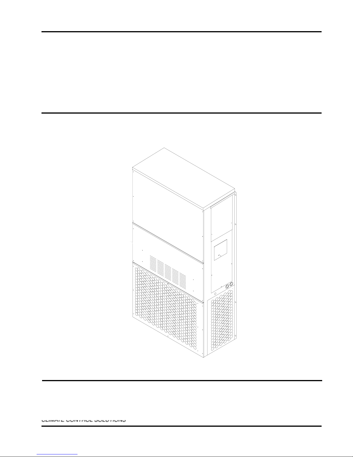
WALL MOUNTED PACKAGED
AIR CONDITIONER
INSTALLATION
INSTRUCTIONS
Models:
WE252 WE301
WE371 WE421
WE482 WE602
WE701
THESE MODELS ALL USE REFRIGERANT R-407C
and ARE FOR 50HZ OPERATION.
Bard Manufacturing Company
Bryan, Ohio 43506
Since 1914...Moving ahead, just as
planned.
MIS-383
Manual No.: 2100-385B
Supersedes: 2100-385A
File: Volume III, Tab 16
Date: 04-25-05
©
Copyright 2002
Page 2

CONTENTS
Getting Other Information
...................................1
Wall Mount General Information
Model Nomenclature ............................................ 2
Shipping Damage ................................................ 5
General ................................................................ 5
Duct Work ............................................................ 5
Filters ................................................................... 6
Fresh Air Intake .................................................... 6
Condensate Drain ................................................ 6
Installation Instructions
Wall Mounting Information ................................... 7
Proper Unit Placement ......................................... 7
Mounting the Unit ................................................. 7
Wiring – Main Power .......................................... 12
Wiring – Low Voltage ......................................... 12
Start Up
Important Installer Note...................................... 14
High Pressure Switch ........................................ 14
Service Hints ...................................................... 14
Sequence of Operations .................................... 14
Compressor Control Module .............................. 14
Adjustments ....................................................... 15
Phase Monitor .................................................... 15
Pressure Service Ports ...................................... 15
Troubleshooting
Fan Blade Setting Dimensions .......................... 16
Removal of Fan Shroud ..................................... 16
Refrigerant Charge ............................................ 16
Cooling Pressures ............................................. 18
Optional Accessories ......................................... 19
R-407C Refrigerant
Service Procedures & Considerations ............... 20
Charging ............................................................ 20
Leaks ................................................................. 20
Figures
Figure 1 Unit Dimensions................................... 4
Figure 2 Fresh Air Damper Assembly ................ 6
Figure 3 Mounting Instructions........................... 8
Figure 4 Electric Heat Clearance ....................... 9
Figure 5 Wall-Mounting Instructions ................. 10
Figure 6 Wall-Mounting Instructions ................. 10
Figure 7 Common Wall-Mounting Instructions . 11
Figure 8 Low Voltage Wiring Diagram ............. 13
Figure 9 Fan Blade Setting .............................. 16
Tables
Table 1 Electric Heat Table ............................... 2
Table 2 Electrical Specifications ....................... 3
Table 3 Thermostat Wire Size ........................ 12
Table 4 Wall Thermostat and
Subbase Combinations...................... 12
Table 5 Fan Blade Setting Dimension ............ 16
Table 6 Suction Line Temperatures ................ 16
Table 7 Rated CFM and ESP ......................... 16
Table 8 Indoor Blower Performance ............... 17
Table 9 Maximum ESP of Operation –
Electric Heat Only .............................. 17
Table 10 Cooling Pressures ............................. 18
Table 11 Optional Accessories ......................... 19
Table 12 R-407C Temperature/Pressure Chart 20
Page 3

GETTING OTHER INFORMATION AND PUBLICATIONS
These publications can help you install the air
conditioner or heat pump. You can usually find these at
your local library or purchase them directly from the
publisher. Be sure to consult current edition of each
standard.
National Electrical Code ........................ ANSI/NFPA 70
Standard for the Installation ................ ANSI/NFPA 90A
of Air Conditioning and
Ventilating Systems
Standard for Warm Air ........................ ANSI/NFPA 90B
Heating and Air
Conditioning Systems
Load Calculation for ............................. ACCA Manual J
Residential Winter and
Summer Air Conditioning
Duct Design for Residential ................ ACCA Manual D
Winter and Summer Air
Conditioning and Equipment
Selection
FOR MORE INFORMATION, CONTACT
THESE PUBLISHERS:
ACCA Air Conditioning Contractors of America
1712 New Hampshire Avenue NW
Washington, DC 20009
Telephone: (202) 483-9370
Fax: (202) 234-4721
ANSI American National Standards Institute
11 West Street, 13th Floor
New York, NY 10036
Telephone: (212) 642-4900
Fax: (212) 302-1286
ASHRAE American Society of Heating Refrigerating,
and Air Conditioning Engineers, Inc.
1791 Tullie Circle, N.E.
Atlanta, GA 30329-2305
Telephone: (404) 636-8400
Fax: (404) 321-5478
NFPA National Fire Protection Association
Batterymarch Park
P.O. Box 9101
Quincy, MA 02269-9901
Telephone: (800) 344-3555
Fax: (617) 984-7057
Manufactured under the following U.S. patent numbers:
5,485,878; 5,301,744; 5,002,116;
4,924,934; 4,875,520; 4,825,936
Manual 2100-385B
Page 1
Page 4
WALL MOUNT GENERAL INFORMATION
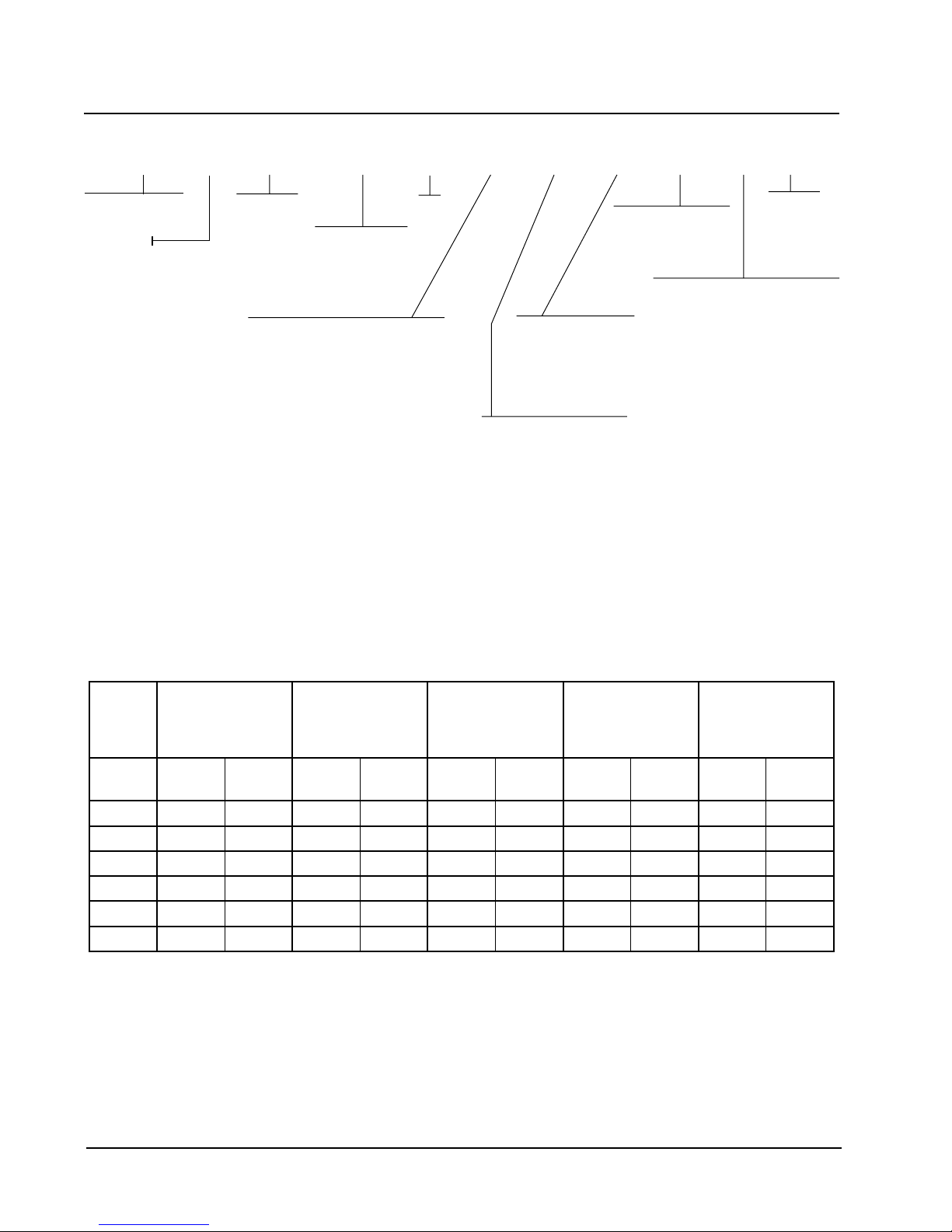
AIR CONDITIONER WALL MOUNT MODEL NOMENCLATURE
WE 42 1 — F 07 X X X X X J
MODEL NUMBER
CAPACITY
25 - 2 TON
30 - 2-1/2 TON
37 - 3 TON
42 - 3-1/2 TON
48 - 4 TON
60 - 5 TON
70 - 6 TON
REVISIONS
VOLTS & PHASE
D - 240/220-50-1
F - 415/380-50-3
VENTILATION OPTIONS
X - BAROMETRIC FRESH AIR DAMPER
B - BLANK-OFF PLATE
M - MOTORIZED FRESH AIR DAMPER
V - COMMERCIAL VENTILATOR
MOTORIZED WITH EXHAUST
E - ECONOMIZER (INTERNAL) - FULLY
MODULATING WITH EXHAUST
R - ENERGY RECOVERY VENTILATOR -
MOTORIZED WITH EXHAUST
KW
COLOR OPTIONS
X-
BEIGE (STANDARD)
1 - WHITE
2 - MESA TAN
4 - BUCKEYE GRAY
5 - DESERT BROWN
FILTER OPTIONS
X - ONE INCH THROWAWAY
W - ONE INCH WASHABLE
P - TWO INCH PLEATED
OUTLET OPTIONS
X - FRONT (STANDARD)
COIL OPTIONS
X - STANDARD
1 - PHENOLIC COATED EVAPORATOR
2 - PHENOLIC COATED CONDENSER
3 - PHENOLIC COATED EVAPORATOR
AND CONDENSER
CONTROL
MODULES
TABLE 1
ELECTRIC HEAT TABLE
D-103EW
sledoMD-252EWF-252EW
WK
1-V042
STTAW
1-V022
STTAW
3-V514
STTAW
3-V083
STTAW
D-173EW
1-V042
STTAW
1-V022
STTAW
0.5110502244844157311050224
0.7 0476656504760665
0.811081276
0.0149991148
0.21 871118049
0.41 0543108211
F-103EW
F-173EW
3-V514
STTAW
3-V083
STTAW
3-V514
STTAW
F-124EW
F-284EW
F-206EW
F-107EW
3-V083
STTAW
Manual 2100-385B
Page 2
Page 5
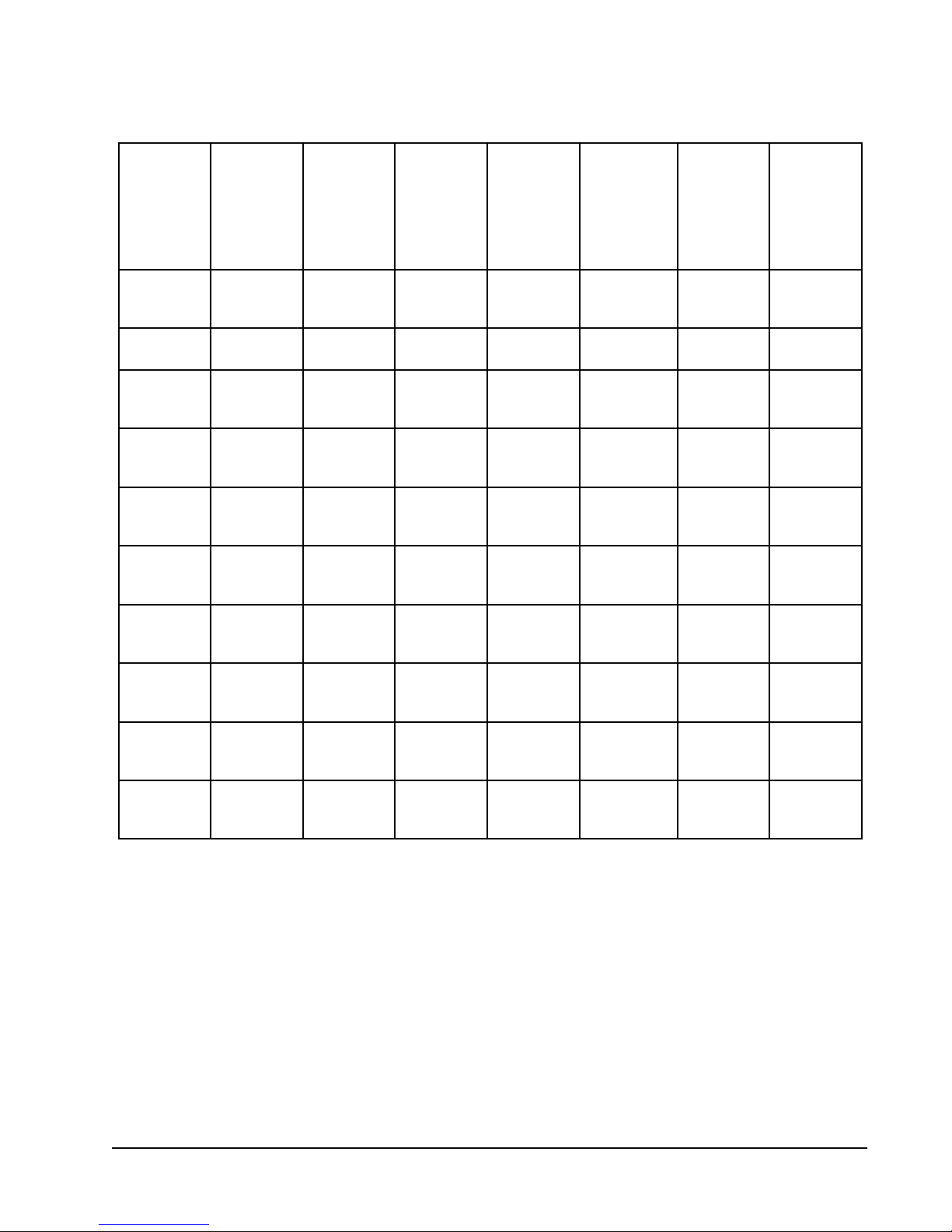
TABLE 2
ELECTRICAL SPECIFICATIONS
1
3
gnitarepO
stloVdetaR
ledoM
Z0D-252EW
50D
80D
Z0F-252EW
50F
Z0D-103EW
50D
01D
Z0F-103EW
70F
21F
Z0D-173EW
50D
01D
Z0F-173EW
70F
21F
Z0F-124EW
70F
41F
Z0F-284EW
70F
41F
Z0F-206EW
70F
41F
Z0F-107EW
70F
41F
1
Maximum size of the time delay fuse or HACR type circuit breaker for protection of field wiring conductors.
2
Based on 75°C copper wire. All wiring must conform to NEC and all local codes.
3
These “Minimum Circuit Ampacity” values are to be used for sizing the field power conductors. Refer to the
National Electric Code (latest revision), Article 310 for power conductor sizing.
Caution: When more than one field power conductor circuit is run through one conduit, the conductors must be
derated. Pay special attention to Note 8 of Table 310 regarding Ampacity Adjustment Factors when more than
three (3) conductors are in a raceway.
IMPORTANT: While this electrical data is presented as a guide, it is important to electrically connect properly sized
fuses and conductor wires in accordance with all existing local codes.
esahPdna
1-022/042452-891
3-083/514654-243
1-022/042452-891
3-083/514654-243
1-022/042452-891
3-083/514654-243
3-083/514654-243
3-083/514654-243
3-083/514654-243
3-083/514654-243
egatloV
egnaR
rebmuN
rewoPdleiF
stiucriC
1
1
1
1
1
1
1
1
1
1
1
1
1
1
1
1
1
1
1
1
1
1
1
1
1
1
1
1
1
muminiM
tiucriC
yticapmA
51
72
34
7
01
22
92
55
9
51
32
42
92
55
11
61
52
11
61
03
31
61
03
51
61
03
91
91
23
mumixaM
lanretxE
esuF
tiucriCro
rekaerB
02
03
54
51
51
53
53
06
51
51
52
53
53
06
51
02
52
51
02
03
02
02
03
02
02
03
52
52
53
2
rewoPdleiF
eziSeriW
21
01
8
41
41
8
8
6
41
41
01
8
8
6
41
21
01
41
21
01
21
21
01
21
21
01
01
01
01
2
dnuorG
eziSeriW
21
01
01
41
41
01
01
01
41
41
01
01
01
01
41
21
01
41
21
01
21
21
01
21
21
01
01
01
01
Manual 2100-385B
Page 3
Page 6
MIS-1665
BACK VIEW
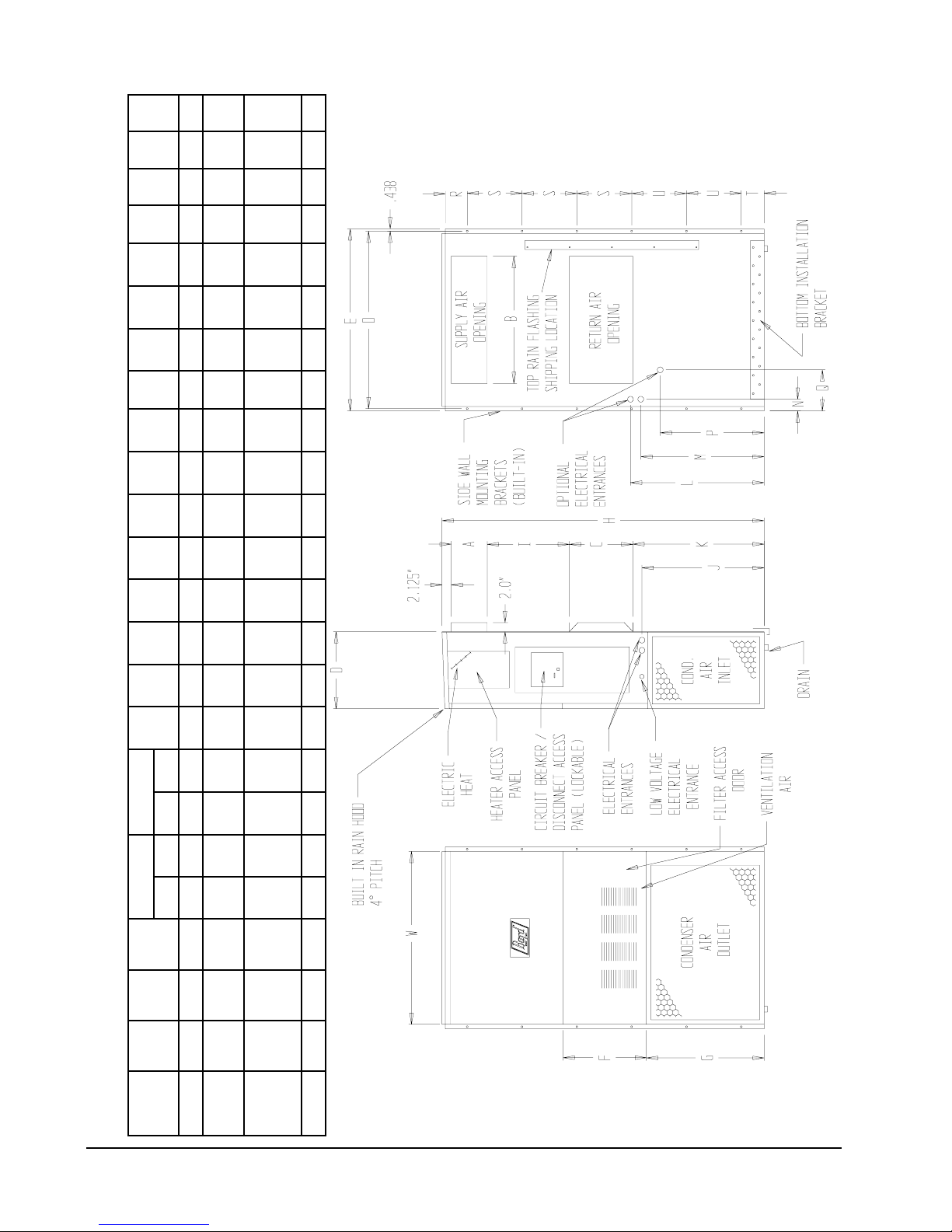
FIGURE 1
UNIT DIMENSIONS (IN INCHES)
EFGI JKLMNOPQRSTUABCB
ylppuSnruteR
thgieH
)H(
htpeD
)D(
htdiW
)W(
ledoM
2.83572.71365.0788.788.7288.3188.720.045.8157.5239.7157.6257.8252.920.7257.291.9357.2241.991.40.210.50.21
103EW
252EW3.33521.71365.0788.788.9188.1188.910.535.8157.5265.0257.6260.8252.920.7236.231.4360.2255.0191.40.210.50.21
173EW
124EW
570.24234.22578.4888.988.9288.5188.9288.3401.9166.130.0386.2349.6296.4334.2373.388.2488.320.0144.10.6188.10.61
284EW
206EW
SIDE VIEW
FRONT VIEW
107EW570.2434.22578.4988.988.9288.5188.9288.3401.9166.140.0386.240.7357.445.2473.388.2488.330.010.20.6188.10.12
Manual 2100-385B
Page 4
Page 7

SHIPPING DAMAGE
DUCT WORK
Upon receipt of equipment, the carton should be
checked for external signs of shipping damage. If
damage is found, the receiving party must contact the
last carrier immediately, preferably in writing,
requesting inspection by the carrier’s agent.
GENERAL
The equipment covered in this manual is to be installed
by trained, experienced service and installation
technicians.
The refrigerant system is completely assembled and
charged. All internal wiring is complete.
The unit is designed for use with or without duct work.
Flanges are provided for attaching the supply and return
ducts.
These instructions explain the recommended method to
install the air cooled self-contained unit and the
electrical wiring connections to the unit.
These instructions and any instructions packaged with
any separate equipment required to make up the entire
air conditioning system should be carefully read before
beginning the installation. Note particularly “Starting
Procedure” and any tags and/or labels attached to the
equipment.
While these instructions are intended as a general
recommended guide, they do not supersede any national
and/or local codes in any way. Authorities having
jurisdiction should be consulted before the installation is
made. See Page 1 for information on codes and
standards.
Size of unit for a proposed installation should be based
on heat loss calculation made according to methods of
Air Conditioning Contractors of America (ACCA). The
air duct should be installed in accordance with the
Standards of the National Fire Protection Association for
the Installation of Air Conditioning and Ventilating
Systems of Other Than Residence Type, NFPA No.
90A, and Residence Type Warm Air Heating and Air
Conditioning Systems, NFPA No. 90B. Where local
regulations are at a variance with instructions, installer
should adhere to local codes.
All duct work, supply and return, must be properly sized
for the design air flow requirement of the equipment.
Air Conditioning Contractors of America (ACCA) is an
excellent guide to proper sizing. All duct work or
portions thereof not in the conditioned space should be
properly insulated in order to both conserve energy and
prevent condensation or moisture damage.
Refer to Table 9 for maximum static pressure available
for duct design.
Design the duct work according to methods given by the
Air Conditioning Contractors of America (ACCA).
When duct runs through unheated spaces, it should be
insulated with a minimum of one inch of insulation. Use
insulation with a vapor barrier on the outside of the
insulation. Flexible joints should be used to connect the
duct work to the equipment in order to keep the noise
transmission to a minimum.
A 1/4 inch clearance to combustible material for the first
3 feet of duct attached to the outlet air frame is required.
See Wall Mounting Instructions and Figures 3 and 4 for
further details.
Ducts through the walls must be insulated and all joints
taped or sealed to prevent air or moisture entering the
wall cavity.
Some installations may not require any return air duct.
A metallic return air grille is required with installations
not requiring a return air duct. The spacing between
louvers on the grille shall not be larger than 5/8 inches.
Any grille that meets the 5/8 inch louver criteria may be
used. It is recommended that Bard Return Air Grille Kit
RG-2 thru RG-5 or RFG-2 thru RFG-5 be installed when
no return duct is used. Contact distributor or factory for
ordering information. If using a return air filter grille,
filters must be of sufficient size to allow a maximum
velocity of 400 fpm.
NOTE: If no return air duct is used, applicable
installation codes may limit this cabinet to
installation only in a single story structure.
Manual 2100-385B
Page 5
Page 8
FILTERS
A 1-inch throwaway filter is supplied with each unit.
The filter slides into position making it easy to service.
This filter can be serviced from the outside by removing
the service door. A 1-inch washable filter and 2-inch
pleated filter are also available as optional accessories.
The internal filter brackets are adjustable to
accommodate the 2-inch filter by bending the metal tabs
holding the 1-inch filter down. There are two tabs on
each side of the filter.
FRESH AIR INTAKE
All units are built with fresh air inlet slots punched in
the service panel.
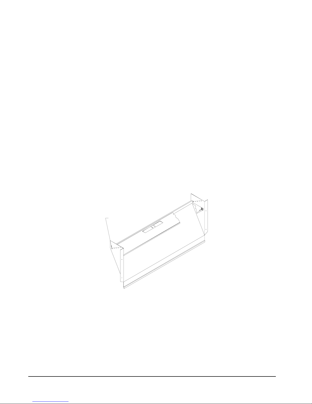
If the unit is equipped with the fresh air damper
assembly, the assembly is shipped already attached to
the unit. The damper blade is locked in the closed
position. To allow the damper to operate, the maximum
and minimum blade position stops must be installed.
See Figure 2.
Capacity and efficiency is based upon the fresh air
blank-off plate in place and is recommended for
maximum energy efficiency.
The blank-off plate is available upon request from the
factory and is installed in place of the fresh air damper
shipped with each unit.
CONDENSATE DRAIN
A plastic drain hose extends from the drain pan at the
top of the unit down to the unit base. There are
openings in the unit base for the drain hose to pass
through. In the event the drain hose is connected to a
drain system of some type, it must be an open or vented
type system to assure proper drainage.
FIGURE 2
FRESH AIR DAMPER ASSEMBLY
BLADE IS LOCKED
CLOSED FOR
SHIPPING
MIS-938
Manual 2100-385B
Page 6
Page 9
WALL MOUNTING INFORMATION
1. Two holes for the supply and return air openings
must be cut through the wall as shown in Figure 3.
2. On wood-frame walls, the wall construction must be
strong and rigid enough to carry the weight of the
unit without transmitting any unit vibration.
3. Concrete block walls must be thoroughly inspected
to insure that they are capable of carrying the weight
of the installed unit.
PROPER UNIT PLACEMENT
Refer to Technical Bulletin TB01-4 “Wall Mount
Equipment Clearance for Proper Operation”. This
bulletin will provide information concerning the
placement of units as to clearance between dual unit
installation (mounted on common wall) of units
discharging against a wall or essentially solid barrier,
and units discharging against opposing (facing) units.
MOUNTING THE UNIT
1. These units are secured by wall mounting brackets
which secure the unit to the outside wall surface at
both sides. A bottom mounting bracket is provided
for ease of installation, but is not required.
2. The unit itself is suitable for 0 inch clearance, but
the supply air duct flange and the first 3 feet of
supply air duct require a minimum of 1/4 inch
clearance to combustible material. However, it is
highly recommended that a 1-inch clearance is used
for ease of installation and maintaining the required
clearance to combustible material. See Figures 3
and 4 for details.
3. Locate and mark lag bolt locations and bottom
bracket location, if desired. See Figure 3.
4. Mount bottom mounting bracket, if used.
INSTALLATION INSTRUCTIONS
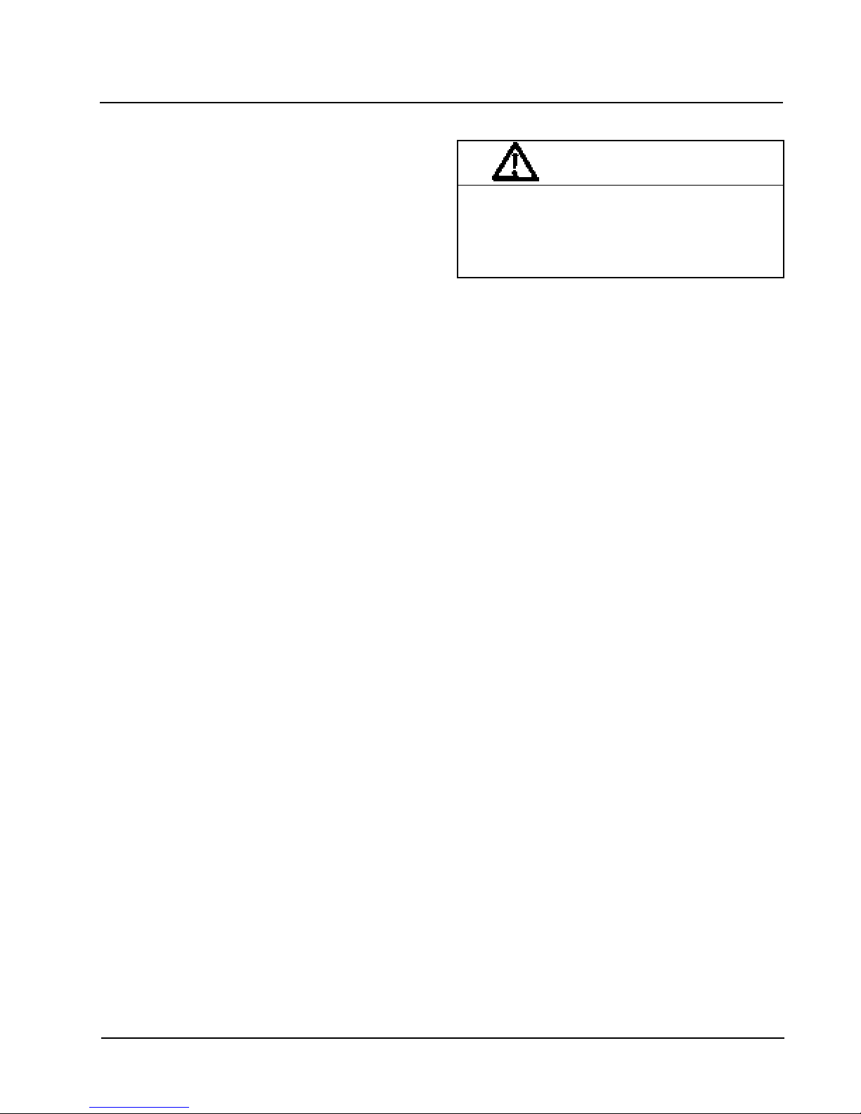
WARNING
Failure to provide the 1/4 inch clearance
between the supply duct and a combustible
surface for the first 3 feet of duct can result in
fire causing damage, injury or death.
5. Hook top rain flashing under back bend of top. Top
rain flashing is shipped secured to the right side of
the back.
6. Position unit in opening and secure with 5/16 lag
bolts; use 7/8 inch diameter flat washers on the lag
bolts.
7. Secure rain flashing to wall and caulk across entire
length of top. See Figure 3.
8. For additional mounting rigidity, the return air and
supply air frames or collars can be drilled and
screwed or welded to the structural wall itself
(depending upon wall construction). Be sure to
observe required clearance if combustible wall.
9. On side by side installations, maintain a minimum of
20 inches clearance on right side to allow access to
control panel and heat strips, and to allow proper
airflow to the outdoor coil. Additional clearance
may be required to meet local or national codes.
MIS-1641
Manual 2100-385B
Page 7
Page 10
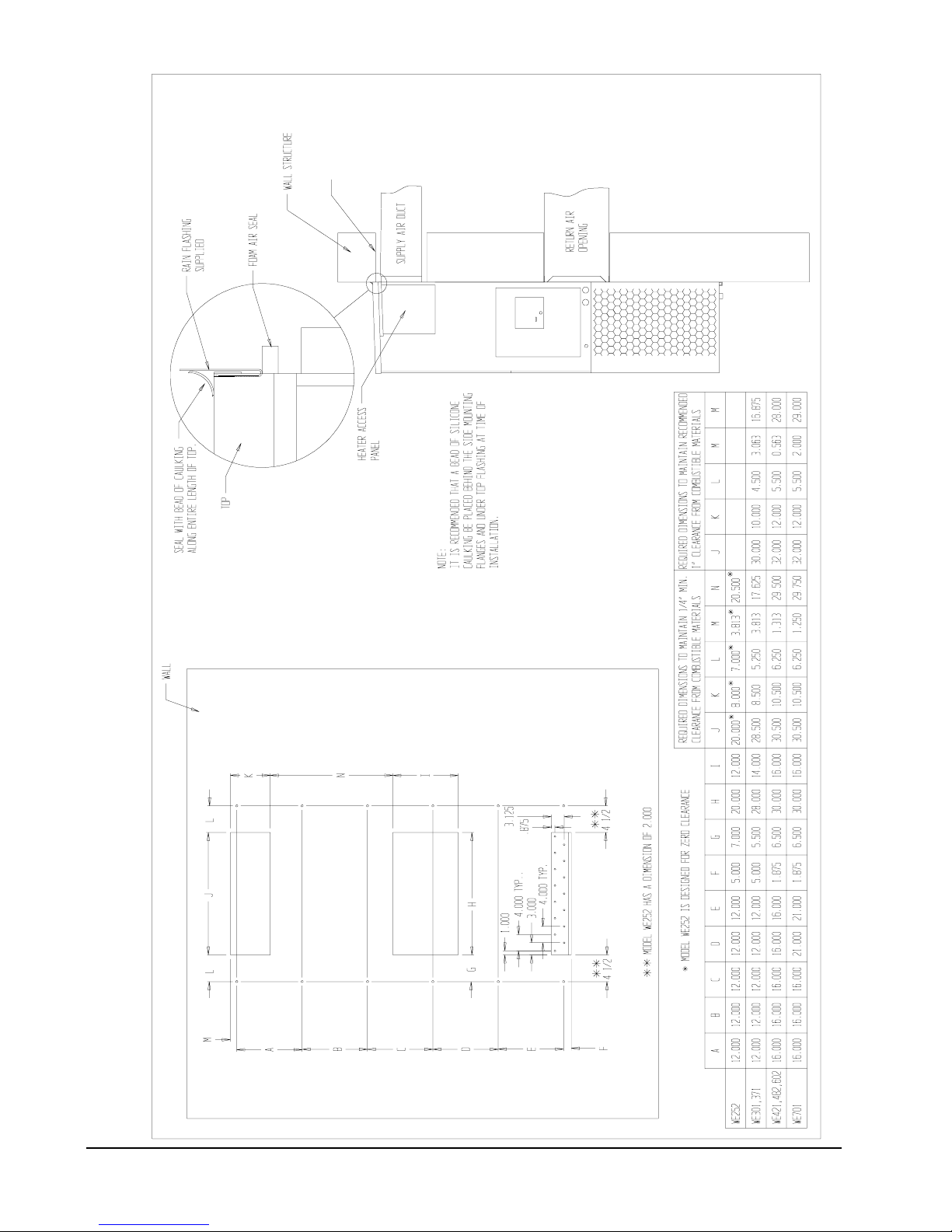
SEE FIGURE 4
FOR FURTHER
DETAILS
MIS-1641
FIGURE 3
MOUNTING INSTRUCTIONS
Manual 2100-385B
Page 8
Page 11
MIS-277
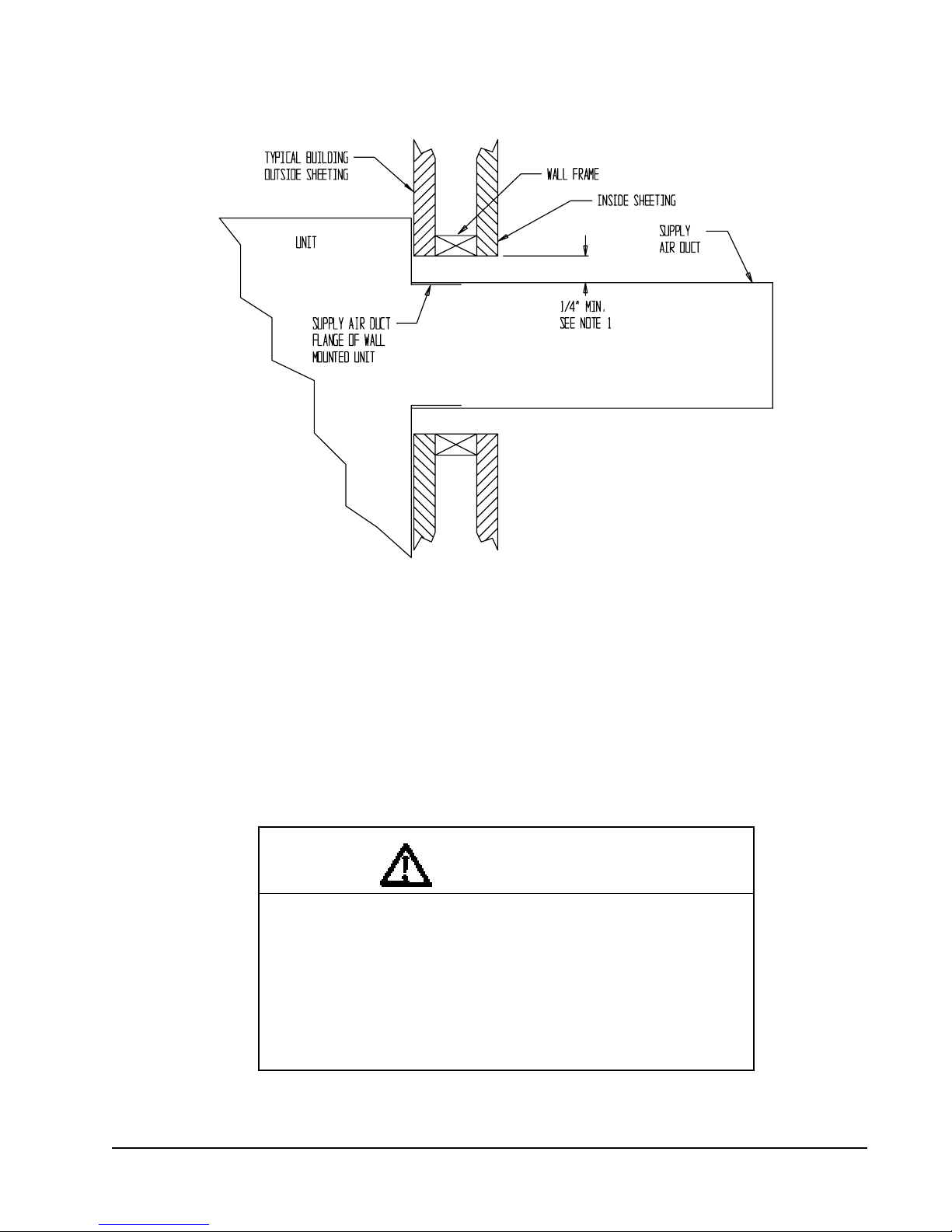
FIGURE 4
ELECTRIC HEAT CLEARANCE
SIDE SECTION VIEW OF SUPPLY AIR
DUCT FOR WALL MOUNTED UNIT
SHOWING 1/4 INCH CLEARANCE TO
COMBUSTIBLE SURFACES.
NOTE:A 1/4 inch clearance to combustible material for the first 3 feet
of duct attached to the outlet air frame is required. However, it
is highly recommended that a 1-inch clearance is used for ease
of installation and maintaining the required clearance to
combustible material
This requirement does not apply to Model WE252 as it is
approved for 0 inch clearance of duct work.
WARNING
A
minimum
the supply air duct and combustible materials. This is required for
the first 3 feet of ducting.
It is important to insure that the 1/4 inch minimum spacing is
maintained at all points.
Failure to do this could result in overheating the combustible
material and may result in a fire causing damage, injury or death.
of 1/4 inch clearance must be maintained between
Manual 2100-385B
Page 9
Page 12
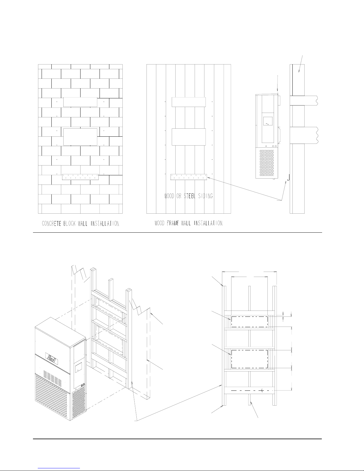
FIGURE 5
WALL-MOUNTING INSTRUCTIONS
SUPPLY AIR
OPENING
RETURN AIR
OPENING
SEE FIGURE 3 – MOUNTING INSTRUCTIONS
SUPPLY AIR
OPENING
RETURN AIR
OPENING
WALL STRUCTURE
FACTORY SUPPLIED RAIN
FLASHING. MOUNT ON UNIT
BEFORE INSTALLATION
BOTTOM MOUNTING
BRACKET. MOUNT ON WALL
BEFORE INSTALLING UNIT.
SUPPLY
AIR DUCT
RETURN
AIR DUCT
FIGURE 6
WALL-MOUNTING INSTRUCTIONS
SEE UNIT DIMENSIONS FIGURE 1
FOR ACTUAL DIMENSIONS
ATTACH TO TOP
PLATE OF WALL
1.000" CLEARANCE
ALL AROUND
INTERIOR FINISHED
WALL OVER FRAME
1.000" CLEARANCE
ALL AROUND
EXTERIOR FINISHED
WALL OVER FRAME
E + 1.000
B
SUPPLY DUCT
OPENING
RETURN DUCT
OPENING
2 x 6
MIS-548
1.000
A
I
C
K
FRAMING MATERIAL
MIS-549
2 x 4'S, 2 x 6'S &/OR
STRUCTURAL STEEL
Manual 2100-385B
Page 10
ATTACH TO BOTTOM
PLATE OF WALL
THIS STRUCTURAL MEMBER LOCATED TO
MATCH STUD SPACING FOR REST OF WALL.
A SECOND MEMBER MAY BE REQUIRED FOR
SOME WALLS.
Page 13
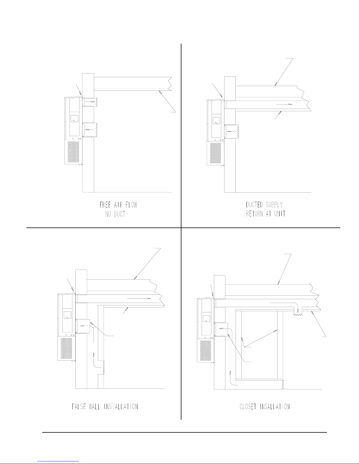
RAIN
FLASHING
COMMON WALL-MOUNTING INSTALLATIONS
RAFTERS
SUPPLY AIR DUCT
W / GRILLE
FINISHED CEILING SURFACE
RETURN AIR OPENING
W / GRILLE
FIGURE 7
RAIN
FLASHING
SUPPLY DUCT MAY BE LOCATED IN
AN ATTIC OR BELOW CEILING
RAFTERS AS SHOWN
RAFTERS
SUPPLY AIR DUCT
FINISHED CEILING SURFACE
RETURN AIR OPENING
W / GRILLE
OUTSIDE
WALL
SUPPLY DUCT MAY BE LOCATED IN AN ATTIC
OR BELOW CEILING RAFTERS AS SHOWN
RAIN
FLASHING
RAFTERS
SUPPLY AIR DUCT
FINISHED CEILING SURFACE
RETURN AIR SPACE
WALL SLEEVE
FALSE WALL
OUTSIDE
WALL
SUPPLY DUCT MAY BE LOCATED IN
AN ATTIC OR BELOW CEILING RAFTERS
AS SHOWN
RAIN
FLASHING
RAFTERS
SUPPLY AIR DUCT
LOWERED
CEILING
CLOSET WALL
SUPPLY AIR
GRILLE
FINISHED CEILING
SURFACE
OUTSIDE
WALL
RETURN AIR GRILLE
OUTSIDE
WALL
WALL SLEEVE
RAISED FLOOR
RETURN AIR
RETURN AIR GRILLE
MIS-550
Manual 2100-385B
Page 11
Page 14
WIRING — MAIN POWER
Refer to the unit rating plate for wire sizing information
and maximum fuse or “HACR" type circuit breaker
size. Each outdoor unit is marked with a “Minimum
Circuit Ampacity”. This means that the field wiring
used must be sized to carry that amount of current.
Depending on the installed KW of electric heat, there
may be two field power circuits required. If this is the
case, the unit serial plate will so indicate. All models
are suitable only for connection with copper wire. Each
unit and/or wiring diagram will be marked “Use Copper
Conductors Only”. These instructions must be adhered
to. Refer to the National Electrical Code (NEC) for
complete current carrying capacity data on the various
insulation grades of wiring material. All wiring must
conform to NEC and all local codes.
The electrical data lists fuse and wire sizes (75° C
copper) for all models, including the most commonly
used heater sizes. Also shown are the number of field
power circuits required for the various models with
heaters.
WIRING — LOW VOLTAGE WIRING
230/208V – 1 phase and 3 phase equipment dual
primary voltage transformers. All equipment leaves the
factory wired on 240V tap. For 208V operation,
reconnect from 240V to 208V tap. The acceptable
operating voltage range for the 240V and 208V taps are:
TAP RANGE
240 253 – 216
208 220 – 187
NOTE: The voltage should be measured at the field
power connection point in the unit and while
the unit is operating at full load (maximum
amperage operating condition).
Five (5) wires should be run from thermostat subbase to
the 24V terminal board in the unit. A five conductor, 18
gauge copper, color-coded thermostat cable is
recommended. The connection points are shown in
Figure 8.
The unit rating plate lists a “Maximum Time Delay
Relay Fuse” or “HACR” type circuit breaker that is to
be used with the equipment. The correct size must be
used for proper circuit protection and also to insure that
there will be no nuisance tripping due to the momentary
high starting current of the compressor motor.
The disconnect access door on this unit may be locked
to prevent unauthorized access to the disconnect. To
convert for the locking capability, bend the tab, located
in the bottom left hand corner of the disconnect opening
under the disconnect access panel, straight out. This tab
will now line up with the slot in the door. When shut, a
padlock may be placed through the hole in the tab
preventing entry.
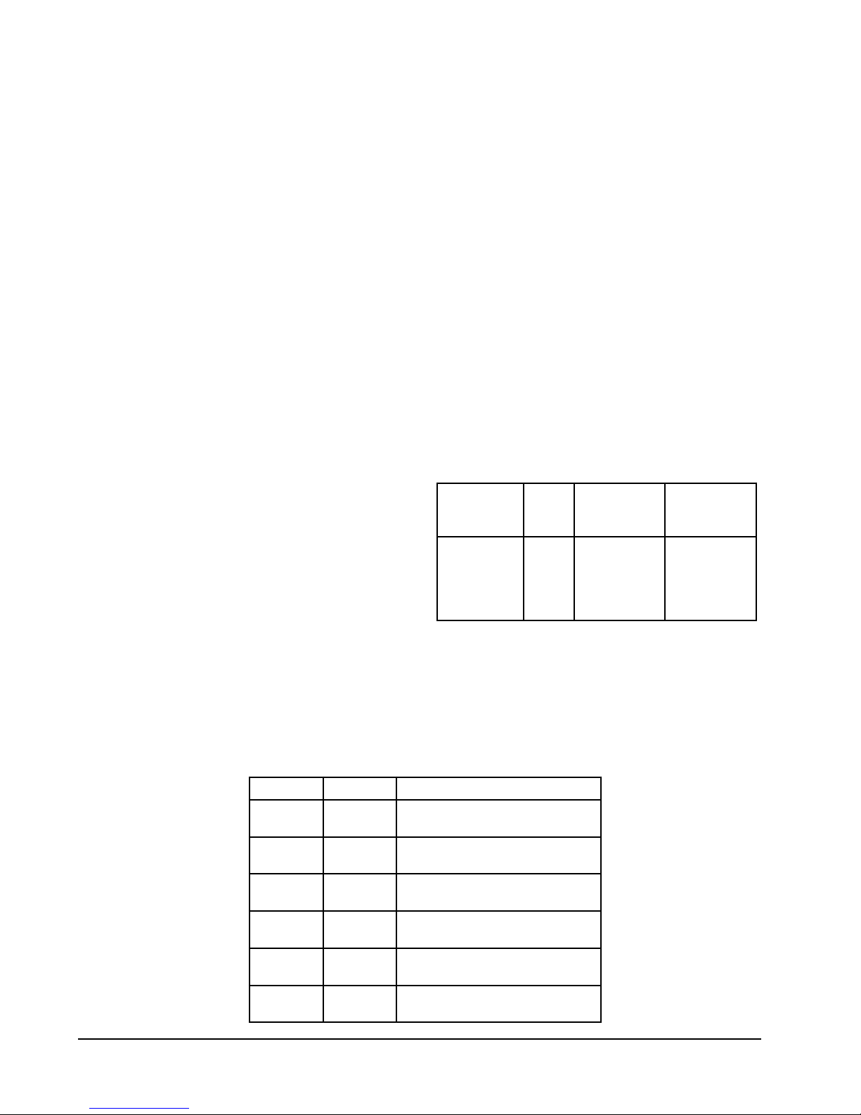
WALL THERMOSTAT AND SUBBASE
COMBINATIONS
tatsomrehTesabbuSserutaeFetanimoderP
200-3048
1113F78T
140-3048
C4308T
910-3048
0671C478T
120-3048
4391D478T
530-3048
08-59F1
340-3048
002-MC
---loocegats1,taehegats1
---taehegats2,loocegats2
---
TABLE 4
300-4048
0221A935Q
210-4048
1001A476Q
210-4048
1001A476Q
TABLE 3
THERMOSTAT WIRE SIZE
remrofsnarT
AVALFeguaGeriW
553.2
loocegats1,taehegats1
no-otua:naFlooc-ffo-taeh:metsyS
no-otua:naFlooc-ffo-taeh:metsyS
taehegats2,loocegats1
no-otua:naFlooc-otua-taeh:metsyS
taehegats2,loocegats2
no-otua:naFlooc-otua-taeh:metsyS
gnimmargorpyad7cinortcelE
loocegats1,taehegats1
no-otua:naFlooc-ffo-taeh:metsyS
mumixaM
niecnatsiD
teeF
eguaG02
eguaG81
eguaG61
eguaG41
eguaG21
54
06
001
061
052
Manual 2100-385B
Page 12
Page 15
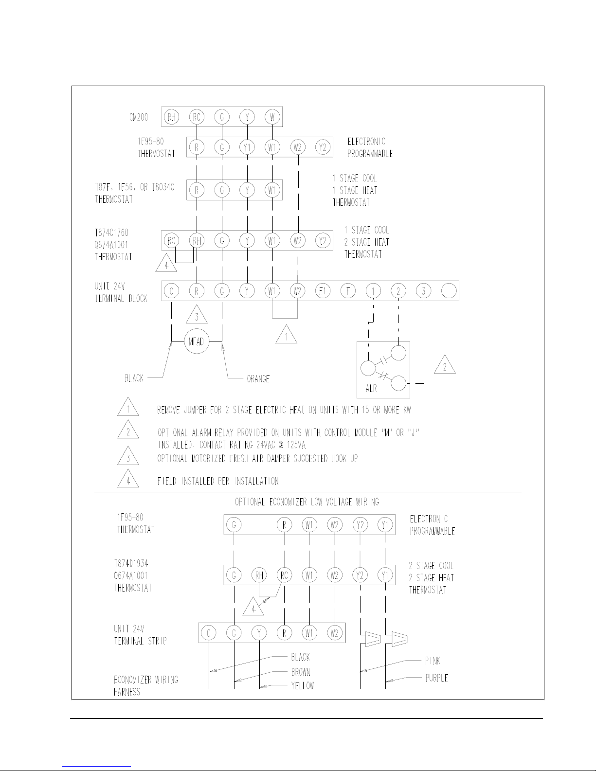
FIGURE 8
LOW VOLTAGE WIRING DIAGRAM
MIS-1373
Manual 2100-385B
Page 13
Page 16

START UP
IMPORTANT INSTALLER NOTE
For improved start-up performance, wash the indoor
coil with a dish washing detergent.
HIGH PRESSURE SWITCH
The WE482, WE602 and WE701 models are supplied
with a remote reset high pressure switch. If tripped, this
pressure switch may be reset by turning the thermostat
off then back on again.
CONDENSER FAN OPERATION
The condenser fan motor on 230/208 volt, one and three
phase 50 Hz models must have fan motor wired on low
speed. These models are factory wired on low speed.
SERVICE HINTS
1. Caution homeowner to maintain clean air filters at
all times. Also, not to needlessly close off supply
and return air registers. This reduces air flow
through the system, which shortens equipment
service life as well as increasing operating costs.
2. Switching to heating cycle at 75° F or higher outside
temperature may cause a nuisance trip of the remote
reset high pressure switch. Turn thermostat off then
on to reset the high pressure switch.
3. Check all power fuses or circuit breakers to be sure
they are the correct rating.
4. Periodic cleaning of the outdoor coil to permit full
and unrestricted airflow circulation is essential.
SEQUENCE OF OPERATION
COOLING – Circuit R-Y makes at thermostat pulling
in compressor contactor, starting the compressor and
outdoor motor. The G (indoor motor) circuit is
automatically completed on any call for cooling
operation or can be energized by manual fan switch on
subbase for constant air circulation. On all 230 volt
units there is a one minute off delay on the blower
motor. 460 volt models do not have an off delay.
HEATING – Circuit R-W1 make at the thermostat
pulling in heat contact for the strip heat and blower
operation. On a call for second stage heat, R-W2 makes
bringing on second heat contactor, if so equipped.
COMPRESSOR CONTROL MODULE
The compressor control module is standard on all
models covered by this manual. The compressor control
is an anti-short cycle/lockout timer with high and low
pressure switch monitoring and alarm relay output.
Adjustable Delay On Make And Break Timer
On initial power up or any time power is interrupted to
the unit the delay on make period begins which will be
2 minutes plus 10% of the delay on break setting. When
the delay on make is complete and the high pressure
switch (and low pressure switch, if employed) is closed,
the compressor contactor is energized. Upon shutdown
the delay on break timer starts and prevents restart until
the delay on break and delay on make periods have
expired.
During routine operation of the unit with no power
interruptions, the compressor will operate on demand
with no delay.
High Pressure Switch and Lockout Sequence
If the high pressure switch opens, the compressor
contactor will de-energize immediately. The lockout
timer will go into a soft lockout and stay in soft lockout
until the high pressure switch closes and the delay on
break time has expired. If the high pressure switch
opens again in this same operating cycle, the unit will
go into manual lockout condition and the alarm relay
circuit will energize. Recycling the wall thermostat
resets the manual lockout.
Low Pressure Switch, Bypass, and Lockout
Sequence (OPTIONAL)
If the low pressure switch opens for more than 120
seconds, the compressor contactor will de-energize and
go into a soft lockout. Regardless the state of the low
pressure switch, the contactor will reenergize after the
delay on make time delay has expired. If the low
pressure switch remains open, or opens again for longer
than 120 seconds the unit will go into manual lockout
condition and the alarm relay circuit will energize.
Recycling the wall thermostat resets the manual lockout.
Alarm Relay Output
Alarm terminal is output connection for applications
where alarm relay is employed. This terminal is
powered whenever compressor is locked out due to HPC
or LPC sequences as described.
NOTE: Both high and low pressure switch controls are
inherently automatic reset devices. The high
pressure switch and low pressure switch cut out
and cut in settings are fixed by specific air
conditioner unit model. The lockout features,
both soft and manual, are a function of the
Compressor Control Module.
Manual 2100-385B
Page 14
Page 17

ADJUSTMENTS
Adjustable Delay on Make and Delay on Break
Timer
The potentiometer is used to select Delay on Break time
from 30 seconds to 5 minutes. Delay on Make (DOM)
timing on power-up and after power interruptions is
equal to 2 minutes plus 10% of Delay on Break (DOB)
setting:
0.5 minute (30 seconds) DOB = 123 second DOM
1.0 minute (60 seconds) DOB = 126 second DOM
2.0 minute (120 seconds) DOB = 132 second DOM
3.0 minute (180 seconds) DOB = 138 second DOM
4.0 minute (240 seconds) DOB = 144 second DOM
5.0 minute (300 seconds) DOB = 150 second DOM
During routine operation of the unit with no power
interruptions, the compressor will operate on demand
with no delay.
Typical Settings for Dual Unit Installation:
Unit 1: DOB set at 2 minutes, and DOM is 132 seconds
Unit 2: DOB set at 4 minutes, and DOM is 144 seconds
PHASE MONITOR
All units with three phase compressors are equipped
with a 3 phase line monitor to prevent compressor
damage due to phase reversal.
The phase monitor in this unit is equipped with two
LEDs. If the Y signal is present at the phase monitor
and phases are correct the green LED will light.
If phases are reversed, the red fault LED will be lit and
compressor operation is inhibited.
If a fault condition occurs, reverse two of the supply
leads to the unit. Do not reverse any of the unit factory
wires as damage may occur.
PRESSURE SERVICE PORTS
Liquid and suction pressure service ports are installed
on all units so that the system operating pressures can be
observed. Pressure tables can be found later in the
manual covering all models. It is imperative to match
the correct pressure table to the unit by model number.
Manual 2100-385B
Page 15
Page 18
TROUBLESHOOTING
FAN BLADE SETTING DIMENSIONS
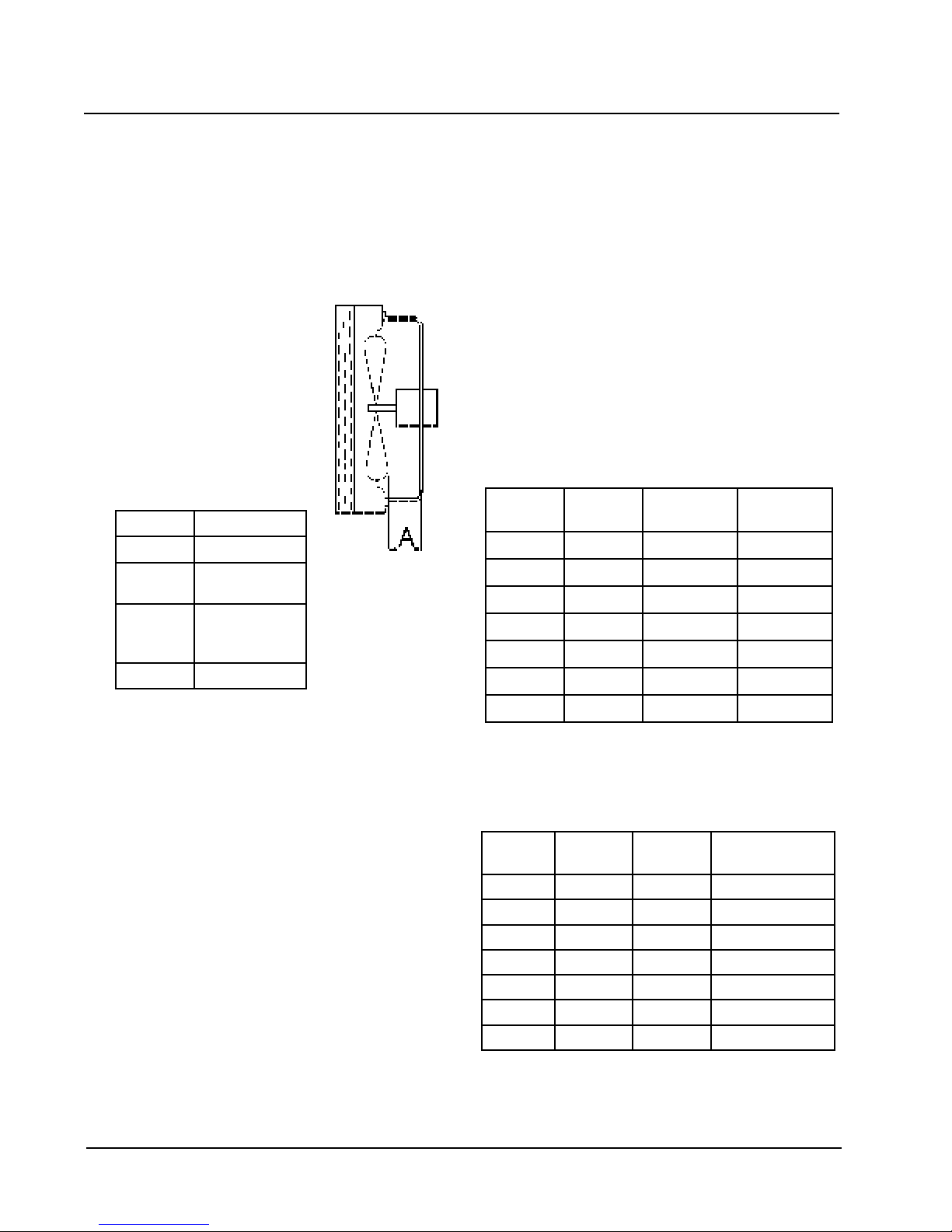
Shown in Figure 9 is the proper method to measure the
fan blade location.
Any service work requiring removal or adjustment in the
fan and/or motor area will require that the fan blade
location be checked.
FIGURE 9
FAN BLADE SETTING
TABLE 5
FAN BLADE DIMENSIONS
ledoMAnoisnemiD
252EW0.1
103EW
173EW
124EW
284EW
206EW
107EW52.1
52.1
57.1
REFRIGERANT CHARGE
The system is charged with R-407C. The correct
quantity is shown on the unit rating plate. Optimum unit
performance will occur with a refrigerant charge
resulting in a suction line temperature (6 inches from
compressor) as shown in Table 6.
The suction line temperatures shown in Table 6 are
based upon 80°F dry bulb / 67°F wet bulb (50 percent
R.H.) temperature and rated airflow across the
evaporator coil during cooling cycle.
See page 20 for instructions in servicing units which
contain refrigerant R-407C
TABLE 6
SUCTION LINE TEMPERATURES
detaR
ledoM
252EW57606-8576-56
103EW05966-4686-66
173EW000195-7506-85
124EW051175-5507-86
284EW572195-7517-96
206EW004185-6556-36
wolfriA
o
59
F
.pmeTDO
28oF
.pmeTDO
REMOVAL OF FAN SHROUD
1. Disconnect all power to unit.
2. Remove the screws holding both grilles – one on
each side of unit – and remove grilles.
3. Remove screws holding fan shroud to condenser and
bottom – 9 screws.
4. Unwire condenser fan motor.
5. Slide complete motor, fan blade, and shroud
assembly out the left side of the unit.
6. Service motor/fan as needed.
7. Reverse steps to reinstall.
107EW584136-1626-06
TABLE 7
RATED CFM and ESP
detaR
ledoM
252EW57622.057-016
103EW05922.5401-558
173EW000102.0011-009
124EW561103.0821-0501
284EW572102.0041-0511
206EW004103.0451-0621
107EW584102.0361-0431
RATED CFM AND RATED ESP WITH BLOWER
SET ON HIGH SPEED.
MFC
detaR
PSE
dednemmoceR
egnaRwolfriA
Manual 2100-385B
Page 16
Page 19
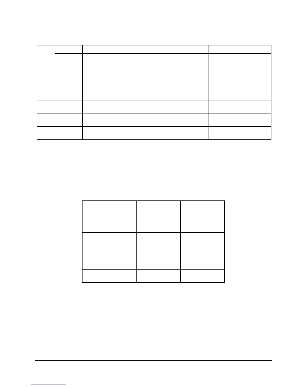
TABLE 8
INDOOR BLOWER PERFORMANCE
CFM (m3/s) at 220V
52EW73EW,03EW84EW,24EW07EW,06EW
niPSE
sehcnI
2
O
H
)aP(
00.
)0(
01.
)52(
02.
)05(
03.
)57(
04.
)001(
/yrD
lioCteW
548/008
)04.0/83.0(
087/038
)73.0/93.0(
027/087
)43.0/73.0(
046/017
)03.0/33.0(
065/046
)62.0/03.0(
Above data is with 1-inch (25mm) standard disposable filter and 1-inch (25mm) washable filter.
For optional 2-inch (51mm) pleated filter reduce ESP by .15 inches (37.33 Pa).
deepShgiH deepSwoL deepShgiH deepSwoL deepShgiH deepSwoL
/yrD
lioCteW
5901/0611
)25.0/55.0(
0601/5111
)05.0/35.0(
0001/0701
)74.0/05.0(
519/0001
)34.0/74.0(
038/529
)93.0/44.0(
/yrD
lioCteW
087/097
)73.0/73.0(
067/577
)53.0/63.0(
047/067
)53.0/53.0(
--/--
--/--
/yrD
lioCteW
0051/5651
)17.0/47.0(
0831-0741
)56.0/96.0(
5821/0631
)16.0/46.0(
0611/0521
)55.0/95.0(
5601/0411
)05.0/45.0(
/yrD
lioCteW
0331/0731
)36.0/56.0(
0421/5821
)95.0/16.0(
0611/0021
)55.0/75.0(
0801/0211
)15.0/35.0(
--/--
/yrD
lioCteW
0661/5281
)87.0/68.0(
0751/0471
47.0/28.0(
001/0661
)17.0/87.0(
0041/0551
)66.0/37.0(
0331/0741
)36.0/96.0(
/yrD
lioCteW
0021/0331
)75.0/36.0(
--/--
--/--
--/--
--/--
TABLE 9
MAXIMUM ESP OF OPERATION
ELECTRIC HEAT ONLY
DEEPSHGIH
LEDOM
50D-252EW
80D-252EW
50F-252EW
50D-173EW,103EW
01D-173EW,103EW
70F-173EW,103EW
21F-173EW,103EW
70F-284EW,124EW
70F-107EW,206EW
21F-284EW,124EW
21F-107EW,206EW
PSE
04.
04.
04.
04.
04.
04.
53.
04.
04.
04.
04.
DEEPSWOL
PSE
-----
-----
-----
04.
53.
03.
52.
04.
04.
04.
04.
Manual 2100-385B
Page 17
Page 20
COOLING
252EW
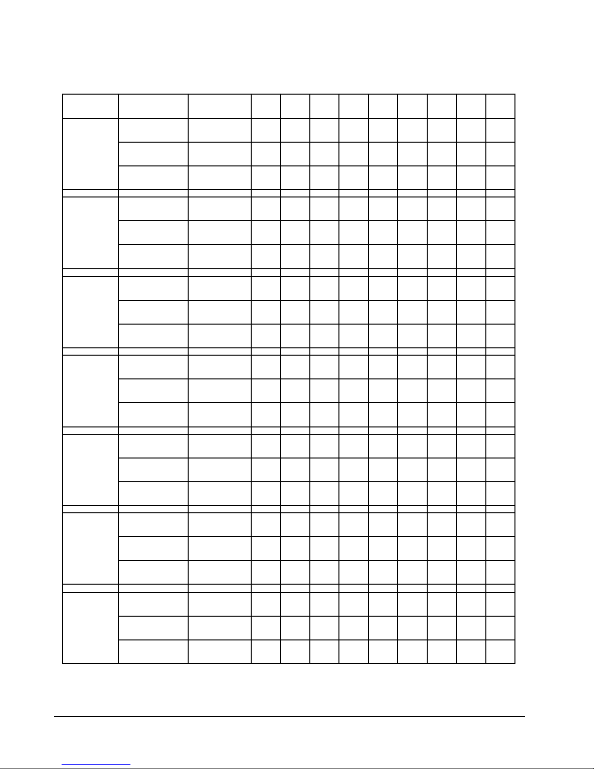
TABLE 10
PRESSURE TABLE
AIR TEMPERATURE ENTERING OUTDOOR COIL
riAnruteR
ledoM
erutarepmeTerusserP°57°08 °58 °09 °59 °001 °501 °011 °511
BD°57
BW°26
BD°08
BW°76
BD°58
BW°27
ediSwoL
ediShgiH
ediSwoL
ediShgiH
ediSwoL
ediShgiH
86
922
37
532
67
342
27
742
77
352
08
262
57
87
462
382
08
38
172
092
38
68
082
003
97
203
58
013
88
123
18
28
323
78
09
343
343
88
133
253
19
463
38
563
98
473
29
783
48
783
09
793
39
114
BD°57
BW°26
103EW
BD°08
BW°76
BD°58
BW°27
BD°57
BW°26
173EW
BD°08
BW°76
BD°58
BW°27
BD°57
BW°26
124EW
BD°08
BW°76
BD°58
BW°27
BD°57
BW°26
284EW
BD°08
BW°76
BD°58
BW°27
ediSwoL
ediShgiH
ediSwoL
ediShgiH
ediSwoL
ediShgiH
ediSwoL
ediShgiH
ediSwoL
ediShgiH
ediSwoL
ediShgiH
ediSwoL
ediShgiH
ediSwoL
ediShgiH
ediSwoL
ediShgiH
ediSwoL
ediShgiH
ediSwoL
ediShgiH
ediSwoL
ediShgiH
87
722
38
332
68
97
422
58
032
88
832
87
532
38
68
942
38
822
98
432
29
242
97
542
58
152
88
142
062
18
142
78
742
09
652
08
152
68
142
752
98
662
58
942
19
552
49
462
18
38
262
082
78
98
962
782
09
29
872
792
28
48
852
772
88
09
562
482
19
39
472
492
38
58
762
482
98
472
29
49
482
68
88
962
982
29
49
672
692
59
79
682
603
58
68
992
813
19
29
703
623
49
59
813
733
58
78
592
513
19
39
303
323
49
69
413
433
88
09
103
913
19
49
69
192
903
723
79
99
103
023
833
98
803
823
59
79
613
633
89
001
723
843
88
833
49
743
79
953
88
533
49
443
79
653
39
633
99
543
201
753
19
29
843
89
753
963
98
953
59
863
89
09
753
69
663
99
973
49
553
463
501
773
49
863
001
773
101
401
093
09
973
69
983
99
183
304
19
873
79
883
001
204
69
373
101
301
383
701
693
49
683
101
693
501
014
BD°57
BW°26
206EW
BD°08
BW°76
BD°58
BW°27
BD°57
BW°26
107EW
BD°08
BW°76
BD°58
BW°27
Low Side pressure ± 2 PSIG
High Side pressure ± 5 PSIG
Tables are based upon rated CFM (airflow) across the evaporator coil. If there is any doubt as to correct
operating charge being in the system, the charge should be removed, system evacuated and recharge to
serial plate instructions.
Manual 2100-385B
Page 18
ediSwoL
ediShgiH
ediSwoL
ediShgiH
ediSwoL
ediShgiH
ediSwoL
ediShgiH
ediSwoL
ediShgiH
ediSwoL
ediShgiH
18
38
252
78
852
09
762
86
37
732
67
542
072
98
772
29
782
07
132
842
57
452
87
362
48
58
092
903
09
792
713
39
49
703
823
27
47
562
382
77
97
272
092
08
28
282
003
68
78
923
943
19
29
39
733
853
59
69
943
67
77
103
18
28
903
923
48
58
023
88
073
49
973
79
173
293
97
123
043
48
943
78
143
98
093
59
004
89
414
97
263
58
88
163
483
09
114
69
224
99
734
18
283
78
173
293
09
604
Page 21
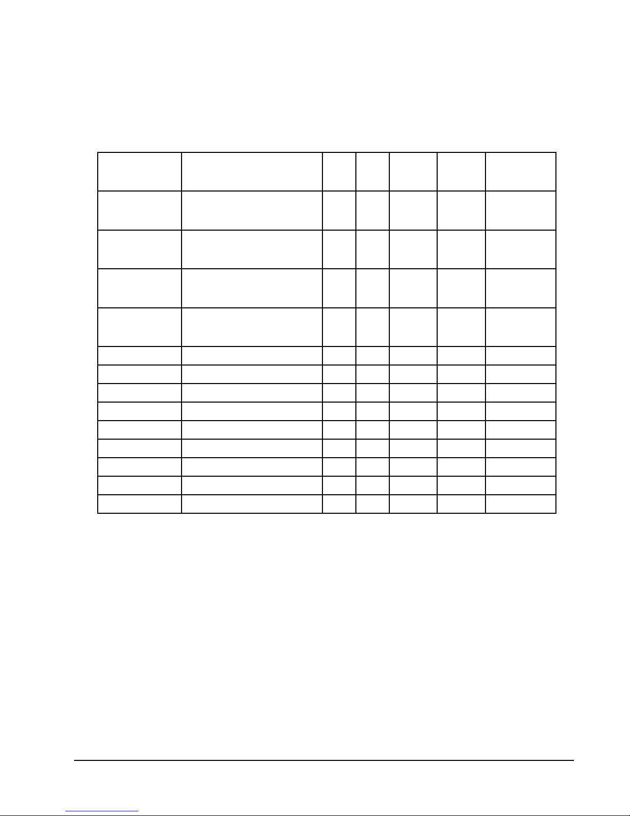
TABLE 11
OPTIONAL ACCESSORIES
rebmuNtraPnoitpircseD
2-POB
3-POB
5-POB
2-DAFB
3-DAFB
5-DAFB
2-DAFM
3-DAFM
5-DAFM
2-VRC
3-VRC
5-VRC
2-MFIE
3-MFIE
5-MFIE
50A-20AWHEegakcaPretaeHX
80A-A20AWHEegakcaPretaeHX
60C-B42HWHEegakcaPretaeHX
50A-30AWHEegakcaPretaeHX
01A-30AWHEegakcaPretaeHX
etalPffOknalB
etalPffOknalB
etalPffOknalB
repmaDriAhserFcirtemoraB
repmaDriAhserFcirtemoraB
repmaDriAhserFcirtemoraB
repmaDriAhserFdezirotoM
repmaDriAhserFdezirotoM
repmaDriAhserFdezirotoM
rotalitneVmooRlaicremmoC
rotalitneVmooRlaicremmoC
rotalitneVmooRlaicremmoC
tsuahxEhtiWrezimonocE
tsuahxEhtiWrezimonocE
tsuahxEhtiWrezimonocE
WE252-D
XX
XX
XX
XX
XX
WE252-F
WE301-D
WE371-D
XX
XX
XX
XX
XX
WE301-F
WE371-F
WE421-F
WE482-F
WE302-F
X
X
X
X
X
WE701-F
60C-30AWHEegakcaPretaeHX
21C-30AWHEegakcaPretaeHX
90C-A50AWHEegakcaPretaeH X
41F-A50AWHEegakcaPretaeH X
Manual 2100-385B
Page 19
Page 22
NOTICE
The refrigeration system in this unit is charged
with refrigerant R-407C
SERVICE PROCEDURE AND
CONSIDERATIONS
Refrigerant R-407C is a blend of three refrigerants,
HFC-32 / HFC-125 / HFC134A. Unlike pure fluids and
azeotropes, blends boil and condense at varying
temperatures for a given pressure. The range over
which the temperature varies is referred to as
temperature glide. R-407C has moderately high
temperature glide between about 9° F and 13° F (5 to
7.2 Celsius) depending upon pressure.
When dealing with blends, pressure temperature tables
are presented in an unconventional manner. Two
temperatures are listed for the same pressure – the liquid
temperature and the vapor temperature.
When a pressure reading is taken from the suction line
or discharge line it is converted to temperature from the
“Vapor Temperature” column on the pressure
temperature chart.
When a pressure reading is taken at the liquid line it is
converted to temperature from the “Liquid
Temperature” column on the pressure temperature chart.
All Bard “WE” models have a pressure tap in the
suction line and the liquid line.
See Pressure Temperature Table 12 on page 21.
CHARGING
When charging a system with R-407C, only the
liquid phase is to be used to ensure proper
refrigerant composition and system performance.
When charging the system into the suction side, care
must be exercised to avoid damage to the compressor.
Because the refrigerant leaving the refrigerant cylinder
must be in liquid phase, it is suggested that a sight glass
be connected between the charging hose and the suction
service port. This will permit you to adjust the cylinder
hand valve so that liquid can leave the cylinder while
allowing vapor to enter the compressor.
The proper refrigerant amount is shown on the unit
rating plate.
LEAKS
If a significant leak develops in the system and a
noticeable change in the system performance occurs,
remove the remaining refrigerant with proper refrigerant
recovery methods, repair the leak with proper industry
practice and methods, and then, after evacuation,
recharge the system with new refrigerant. Again, charge
only with liquid refrigerant to ensure that the proper
composition is in the system.
CAUTION
Leak checking should never be done with a
mixture of R-407C and air. Leak checking
can be performed safely with a mixture of
R-407C and nitrogen. Make sure the leak
detector is capable of detecting R-407C
before using.
Notice:
When opening a system, care must be taken to
minimize the system exposure to atmosphere.
Exposure for more than five minutes could
shorten the life of the system. The compressor in
this system contains Polyol Ester (POE) oil.
POE's are very hygroscopic. They absorb
moisture from the atmosphere at a much faster
rate than mineral oils used in R-22 systems.
This system has a factory-installed filter drier in the
liquid line. It is highly recommended that the filter drier
be replaced when the system has been open. Make sure
the replacement filter drier is suitable and approved for
use with R-407C.
Before recharging the system, a vacuum of 250 microns
or less must be achieved.
Manual 2100-385B
Page 20
Page 23
TABLE 12
R-407C SATURATED VAPOR/LIQUID
TEMPERATURE/PRESSURE CHART
erusserP
)GISP(
02
22
42
62
82
03
23
43
63
83
04
24
44
64
84
05
25
45
65
85
06
26
46
66
86
07
27
47
67
87
08
28
48
68
88
09
29
49
69
89
001
501
011
511
021
521
031
531
041
541
.pmeTdiuqiL
)°F(
7.01-
2.8-
7.5-
4.3-
1.1-
1.1
2.3
3.5
3.7
2.9
1.11
9.21
7.41
4.61
1.81
7.91
3.12
9.22
4.42
9.52
4.72
8.82
2.03
6.13
0.33
3.43
6.53
9.63
2.83
4.93
6.04
9.14
0.34
2.44
4.54
5.64
6.74
7.84
8.94
9.05
9.15
5.45
0.75
5.95
8.16
1.46
4.66
5.86
7.07
8.27
.pmeTropaV
)°F(
5.1
0.4
4.6
7.8
0.11
1.31
2.51
2.71
2.91
0.12
9.22
7.42
4.62
1.82
7.92
3.13
9.23
4.43
9.53
4.73
8.83
2.04
6.14
0.34
3.44
6.54
9.64
1.84
3.94
6.05
8.15
9.25
1.45
2.55
3.65
4.75
5.85
6.95
7.06
7.16
7.26
2.56
7.76
0.07
3.27
8.47
7.67
8.87
9.08
9.28
erusserP
)GISP(
051
551
061
561
071
571
081
581
091
591
002
502
012
512
022
522
032
532
042
542
052
552
062
562
072
572
082
582
092
592
003
503
013
513
023
523
033
533
043
543
053
553
063
563
073
573
083
583
093
593
.pmeTdiuqiL
)°F(
8.47
8.67
7.87
6.08
5.28
3.48
1.68
8.78
6.98
3.19
9.29
6.49
2.69
7.79
3.99
8.001
3.201
8.301
3.501
7.601
2.801
6.901
0.111
3.211
7.311
0.511
3.611
6.711
9.811
2.021
4.121
7.221
9.321
1.521
3.621
5.721
7.821
8.921
0.131
1.231
2.331
3.431
4.531
5.631
6.731
7.831
8.931
8.041
8.141
9.241
.pmeTropaV
)°F(
9.48
8.68
7.88
5.09
3.29
0.49
8.59
5.79
1.99
7.001
3.201
9.301
4.501
0.701
4.801
9.901
4.111
8.211
2.411
6.511
9.611
2.811
6.911
9.021
1.221
4.321
7.421
9.521
1.721
3.821
5.921
7.031
8.131
0.331
1.431
2.531
3.631
4.731
5.831
6.931
6.041
7.141
7.241
7.341
7.441
7.541
7.641
7.741
7.841
6.941
Manual 2100-385B
Page 21
 Loading...