


INSTALLATION INSTRUCTIONS
WALL MOUNTED
PACKAGE AIR CONDITIONERS
MODELS
W17A1 W17L1
W18A1 W18L1
W24A1 W24L1
W30A1 W30L1
W36A1 W36L1
W42A1 W42L1
W48A1 W48L1
W60A1 W60L1
W70A1 W70L1
Bard Manufacturing Company, Inc.
Bryan, Ohio 43506
Since 1914...Moving ahead just as planned.
Manual : 2100-508F
Supersedes: 2100-508E
File: Volume III Tab 16
Date: 12-15-11
Manual 2100-508F
Page 1 of 25

Contents
Getting Other Information and Publications 3
Wall Mount General Information
Wall Mount Model Nomenclature ............................ 4
Shipping Damage .................................................... 4
General ................................................................ 4
Duct Work ................................................................ 5
Filters ................................................................ 5
Fresh Air Intake ....................................................... 5
Condensate Drain.................................................... 5
Installation Instructions
Wall Mounting Information....................................... 6
Mounting the Unit .................................................... 6
Clearances Required............................................... 6
Minimum Clearances ............................................... 6
Wiring – Main Power ............................................. 14
Wiring – Low Voltage Wiring ................................. 14
Figures
Figure 1 Fresh Air Damper Assembly ................... 5
Figure 2 Unit Dimensions...................................... 7
Figure 3A Mounting Instructions .............................. 8
Figure 3B
Figure 3C
Figure 4 Electric Heat Clearance .........................11
Figure 5 Wall Mounting Instructions .................... 12
Figure 6 Wall Mounting Instructions .................... 12
Figure 7 Common Wall Mounting Installations .... 13
Figure 8 Fan Blade Setting ................................. 18
Mounting Instructions - W17 – 36 .............. 9
Mounting Instructions - W42, 48, 60, 70 ...10
Start Up
General .............................................................. 15
Topping Off System Charge................................... 15
Safety Practices..................................................... 15
Important Installer Note ......................................... 16
High Pressure Switch ............................................ 16
Three Phase Scroll Compressor............................ 16
Phase Monitor ....................................................... 16
Condenser Fan Operation ..................................... 16
Service Hints ......................................................... 16
Sequence of Operation.......................................... 17
Compressor Control Module.................................. 17
Adjustments........................................................... 17
Pressure Service Ports.......................................... 17
Troubleshooting
Fan Blade Setting Dimensions .............................. 18
Removal of Fan Shroud......................................... 18
Refrigerant Charge ................................................ 18
Tables
Table 1 Fan Blade Dimensions.......................... 18
Table 2 Cooling Pressure .................................. 19
Table 3 Electrical Specifications W**A .............. 20
Table 4 Electrical Specifications W**L ............... 21
Table 5 Recommended Airflow .......................... 22
Table 6 Indoor Blower Performance .................. 22
Table 7 Maximum ESP Electric Heat Only........ 22
Table 8 Electric Heat ......................................... 23
Table 9 Optional Accessories ............................ 24
Table 10 Vent & Control Options ......................... 25
Manual 2100-508F
Page 2 of 25

GETTING OTHER INFORMATION AND PUBLICATIONS
These publications can help you install the air
conditioner or heat pump. You can usually find these at
your local library or purchase them directly from the
publisher. Be sure to consult current edition of each
standard.
National Electrical Code ...................... ANSI/NFPA 70
Standard for the Installation .............. ANSI/NFPA 90A
of Air Conditioning and Ventilating Systems
Standard for Warm Air ...................... ANSI/NFPA 90B
Heating and Air Conditioning Systems
Load Calculation for............................ ACCA Manual J
Residential Winter and Summer Air Conditioning
Duct Design for Residential .............. ACCA Manual D
Winter and Summer Air Conditioning and Equipment
Selection
FOR MORE INFORMATION, CONTACT
THESE PUBLISHERS:
ACCA Air Conditioning Contractors of America
1712 New Hampshire Ave. N.W.
Washington, DC 20009
Telephone: (202) 483-9370
Fax: (202) 234-4721
ANSI American National Standards Institute
11 West Street, 13th Floor
New York, NY 10036
Telephone: (212) 642-4900
Fax: (212) 302-1286
ASHRAE American Society of Heating, Refrigeration
and Air Conditioning Engineers, Inc.
1791 Tullie Circle, N.E.
Atlanta, GA 30329-2305
Telephone: (404) 636-8400
Fax: (404) 321-5478
NFPA National Fire Protection Association
Batterymarch Park
P.O. Box 9101
Quincy, MA 02269-9901
Telephone: (800) 344-3555
Fax: (617) 984-7057
Manual 2100-508F
Page 3 of 25
WALL MOUNT GENERAL INFORMATION
AIR CONDITIONER WALL MOUNT MODEL NOMENCLATURE
W 42 A 1– A 10 X X X X X A
MODEL NUMBER
CAPACITY
½
Ton
18 - 1
24 - 2 Ton
½ Ton
30 - 2
36 - 3 Ton
42 - 3½ Ton
48 - 4 Ton
60 - 5 Ton
70 - 6 Ton
NOTE: Vent options X, B and M are without exhaust capability. May require separate field supplied barometric relief in building.
A - Right Hand Air Conditioner
L - Left Hand Air Conditioner
VENTILATION OPTIONS
X - Barometric Fresh Air Damper (Standard)
B - Blank-off Plate
M - Motorized Fresh Air Damper
V - Commercial Ventilator - Motorized with Exhaust
E - Economizer (Internal) - Fully Modulating with Exhaust
R - Energy Recovery Ventilator - Motorized with Exhaust
(See Spec. Sheet S3397)
SHIPPING DAMAGE
Upon receipt of equipment, the carton should be
checked for external signs of shipping damage. If
damage is found, the receiving party must contact the
last carrier immediately, preferably in writing,
requesting inspection by the carrier’s agent.
REVISIONS
VOLTS & PHASE
A - 230/208/60/1
B - 230/208/60/3
C - 460/60/3
KW
COLOR OPTIONS
X - Beige (Standard)
1 - White
4 - Buckeye Gray
5 - Desert Brown
6 - Dark Bronze
A - Aluminum
S - Stainless Steel
FILTER OPTIONS
X - One Inch Throwaway (Standard)
W - One Inch Washable
P - Two Inch Pleated
OUTLET OPTIONS
X - Front (Standard)
T - Top Outlet (W30A, W36A Only)
These instructions and any instructions packaged with
any separate equipment required to make up the entire
air conditioning system should be carefully read before
beginning the installation. Note particularly “Starting
Procedure” and any tags and/or labels attached to the
equipment.
CONTROL MODULES
(See Spec. Sheet S3397)
COIL OPTIONS
X - Standard
1 - Phenolic Coated Evaporator
2 - Phenolic Coated Condenser
3 - Phenolic Coated Evaporator
and Condenser
While these instructions are intended as a general
GENERAL
The equipment covered in this manual is to be installed
by trained, experienced service and installation
technicians.
The refrigerant system is completely assembled and
charged. All internal wiring is complete.
The unit is designed for use with or without duct work.
Flanges are provided for attaching the supply and return
ducts.
These instructions explain the recommended method to
install the air cooled self-contained unit and the
electrical wiring connections to the unit.
recommended guide, they do not supersede any national
and/or local codes in any way. Authorities having
jurisdiction should be consulted before the installation is
made. See Page 3 for information on codes and
standards.
Size of unit for a proposed installation should be based
on heat loss calculation made according to methods of
Air Conditioning Contractors of America (ACCA). The
air duct should be installed in accordance with the
Standards of the National Fire Protection Association
for the Installation of Air Conditioning and Ventilating
Systems of Other Than Residence Type, NFPA No.
90A, and Residence Type Warm Air Heating and Air
Conditioning Systems, NFPA No. 90B. Where local
regulations are at a variance with instructions, installer
should adhere to local codes.
Manual 2100-508F
Page 4 of 25
DUCT WORK
All duct work, supply and return, must be properly sized
for the design airflow requirement of the equipment. Air
Conditioning Contractors of America (ACCA) is an
excellent guide to proper sizing. All duct work or portions
thereof not in the conditioned space should be properly
insulated in order to both conserve energy and prevent
condensation or moisture damage.
Refer to Maximum ESP of operation Electric Heat Table 6.
FILTERS
A 1-inch throwaway filter is standard with each unit.
The filter slides into position making it easy to service.
This filter can be serviced from the outside by removing
the filter access panel. A 1-inch washable filter and 2inch pleated filter are also available as optional
accessories. The internal filter brackets are adjustable
to accommodate the 2-inch filter by bending two (2)
tabs down on each side of the filter support bracket.
Design the duct work according to methods given by the Air
Conditioning Contractors of America (ACCA). When duct
runs through unheated spaces, it should be insulated with a
minimum of one inch of insulation. Use insulation with a
vapor barrier on the outside of the insulation. Flexible joints
should be used to connect the duct work to the equipment in
order to keep the noise transmission to a minimum.
Models W17 - W24 as approved for zero inch clearance to
the supply duct. For model series W30, W36, W42, W48,
W60 and W70 a 1/4 inch clearance to combustible material
for the first three feet of duct attached to the outlet air frame
is required. See Wall Mounting Instructions and Figures 3
and 4 for further details.
Ducts through the walls must be insulated and all joints
taped or sealed to prevent air or moisture entering the wall
cavity.
Some installations may not require any return air duct. A
metallic return air grille is required with installations not
requiring a return air duct. The spacing between louvers on
the grille shall not be larger than 5/8 inch.
Any grille that meets with 5/8 inch louver criteria may be
used. It is recommended that Bard Return Air Grille Kit
RG2 through RG5 or RFG2 through RFG5 be installed
when no return duct is used. Contact distributor or factory
for ordering information. If using a return air filter grille,
filters must be of sufficient size to allow a maximum
velocity of 400 fpm.
FRESH AIR INTAKE
All units are built with fresh air inlet slots punched in
the service door.
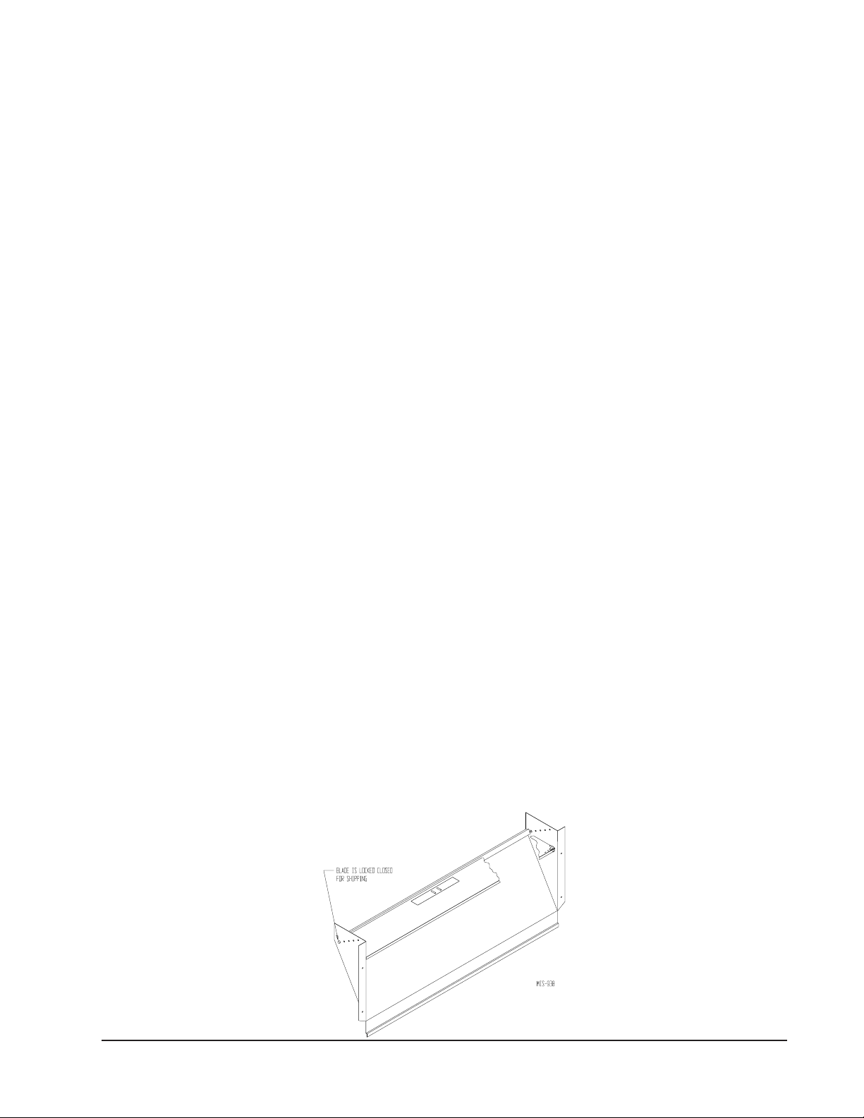
If the unit is equipped with a fresh air damper assembly,
the assembly is shipped already attached to the unit.
The damper blade is locked in the closed position. To
allow the damper to operate, the maximum and
minimum blade position stops must be installed. See
Figure 1.
All capacity, efficiency and cost of operation
information is based upon the fresh air blank-off plate in
place and is recommended for maximum energy
efficiency.
The blank-off plate is available upon request from the
factory and is installed in place of the fresh air damper
shipped with each unit.
CONDENSATE DRAIN
A plastic drain hose extends from the drain pan at the
top of the unit down to the unit base. There are
openings in the unit base for the drain hose to pass
through. In the event the drain hose is connected to a
drain system of some type, it must be an open or vented
type system to assure proper drainage.
NOTE: If no return air duct is used, applicable installation
codes may limit this cabinet to installation only in a
single story structure.
FIGURE 1
FRESH AIR DAMPER
Manual 2100-508F
Page 5 of 25
INSTALLATION INSTRUCTIONS
WALL MOUNTING INFORMATION
1. Two holes for the supply and return air openings
must be cut through the wall as shown in Figure 3.
2. On wood frame walls, the wall construction must be
strong and rigid enough to carry the weight of the
unit without transmitting any unit vibration.
3. Concrete block walls must be thoroughly inspected
to insure that they are capable of carrying the weight
of the installed unit.
MOUNTING THE UNIT
1. These units are secured by wall mounting brackets
which secure the unit to the outside wall surface at
both sides. A bottom mounting bracket, attached to
skid for shipping, is provided for ease of installation,
but is not required.
2. The unit itself is suitable for 0 inch clearance, but
the supply air duct flange and the first 3 feet of
supply air duct require a minimum of 1/4 inch
clearance to combustible material for model series
W30, W36, W42, W48, W60 and W70. However, it
is generally recommended that a 1-inch clearance is
used for ease of installation and maintaining the
required clearance to combustible material. See
Figure 3 for details on opening sizes.
3. Locate and mark lag bolt locations and bottom
mounting bracket location. See Figure 3.
WARNING
Failure to provide the 1/4 inch clearance
between the supply duct and a combustible
surface for the first 3 feet of duct can result in
fire causing damage, injury or death.
6. Position unit in opening and secure with 5/16 lag
bolts; use 7/8 inch diameter flat washers on the lag
bolts.
7. Secure rain flashing to wall and caulk across entire
length of top. See Figure 3.
8. For additional mounting rigidity, the return air and
supply air frames or collars can be drilled and
screwed or welded to the structural wall itself
(depending upon wall construction). Be sure to
observe required clearance if combustible wall.
9. On side-by-side installations, maintain a minimum
of 20 inches clearance on right side to allow access
to control panel and heat strips, and to allow proper
airflow to the outdoor coil. Additional clearance
may be required to meet local or national codes.
4. Mount bottom mounting bracket.
5. Hook top rain flashing, attached to front - right of
supply flange for shipping, under back bend of top.
sseccAecivreSrofderiuqeRsecnaraelC
wolfriAresnednoCetauqedAdna
SLEDOM EDISTFEL EDISTHGIR
A63W,A03W,A42W,A81W,A71W "51 "02
L63W,L03W,L42W,L81W,L71W "02 "51
A07W,A06W,A84W,A24W "02 "02
L07W,L06W,L84W,L24W "02 "02
NOTE: For side by side installation of two (2) W**A models there
must be 20" between units. This can be reduced to 15" by using
a W**L model (left side compressor and controls) for the left unit
and WA (right side compressor and controls) for right unit.
See W**A Specification S3397 & W**L Specification S3400.
Manual 2100-508F
Page 6 of 25
otderiuqeRsecnaraelCmuminiM
slairetaMelbitsubmoC
SLEDOM
L,A42W/L,A81W/L,A71W"0"0
L,A63W/L,A03W"4/1"0
L,A84W/L,A24W
L,A07W/L,A06W
TCUDRIAYLPPUS
TEEFEERHTTSRIF
"4/1"0
TENIBAC
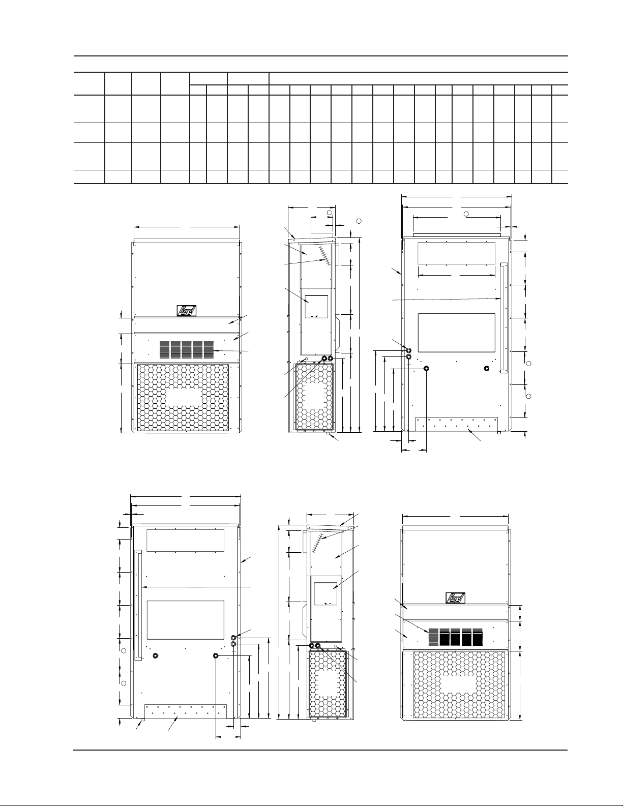
FIGURE 2
D
HTDIW
LEDOM
)W(
HTPED
)D(
THGIEH
)H(
L,A71W
L,A81W
003.33521.71365.0788.788.9188.1188.9100.5300.1157.5265.0257.6260.8252.9200.7236.231.4360.2255.0191.400.2100.5
L,A42W
L,A03W
002.83521.71365.0788.788.7288.3188.7200.0400.1157.5239.7157.6257.8252.9200.7257.291.9357.2241.991.400.2100.5
L,A63W
L,A24W
L,A84W
570.24234.22578.4888.988.9288.5188.9288.3436.3166.1300.0386.2349.6296.4334.2373.388.2488.3200.0144.100.6188.1
L,A06W
L,A07W570.24234.22578.4988.988.9288.5188.9288.3436.3166.1400.0386.2449.6396.4434.2473.388.2488.3300.0144.100.6188.1
All dimensions are in inches. Dimensional drawings are not to scale.
W**A
RIGHT
W
UNIT
5.75
F
G
Condenser
Air Outlet
YLPPUSNRUTER
AB C B E F G I J K L MNO P QRST
E
Built In
Rain Hood
4° Pitch
Heater
Access
Panel
Electric
C. Breaker/
Disconnect
Access Panel
(Lockable)
Filter Access
Panel
Vent Option
Door
Ventilation
Air
Low Voltage
Electrical
Entrance
High Voltage
Electrical
Entrance
Heat
D
Cond.
Air
Inlet
7.88
2
2
1.00
2.13
Side Wall
A
Mounting
Brackets
(Built In)
I
Top Rain
Flashing
Shipping
Location
Optional
C H
Electrical
Entrances
K
J
L
M
P
O
2
31.88
Supply Air Openi ng
B
Return Air Openi ng
.44
)lanimoN(stnemeriuqeRnoitallatsnIdnalarutcetihcrAroftinUcisaBfosnoisnemi
R
S
S
S
1
S
1
S
Front View
Side View
Drain
1 Dimension is 21.00 inches on W70A & W70L models.
2 Optional top outlet (factory installed only) for W30A and W36A models only.
W**L
LEFT
UNIT
R
S
S
S
S
S
T
1
1
Drain
.44
Supply Air Openi ng
Return Air Openi ng
Bottom
Installation
Bracket
E
O
Back View
9.06
Side Wall
Mounting
Brackets
(Built In)
Top Rain
Flashing
Shipping
Location
Optional
Electrical
Entrances
M
P
2.63
D
2.13
A
I
C
H
K
L
Cond.
J
Air
Inlet
Built In
Rain Hood
4° Pitch
Electric
Heat
Heater
Access
Panel
C. Breaker/
Disconnect
Access Panel
(Lockable)
Filter Access
Low Voltage
Electrical
Entrance
High Voltage
Electrical
Entrance
N
Panel
Ventilation
Vent Option
Door
T
W
Bottom Installation
Bracket
MIS-2487 B
5.75
F
G
Back View
Q
Air
Condenser
Air Outlet
Front ViewSide View
MIS-2488 B
Manual 2100-508F
Page 7 of 25
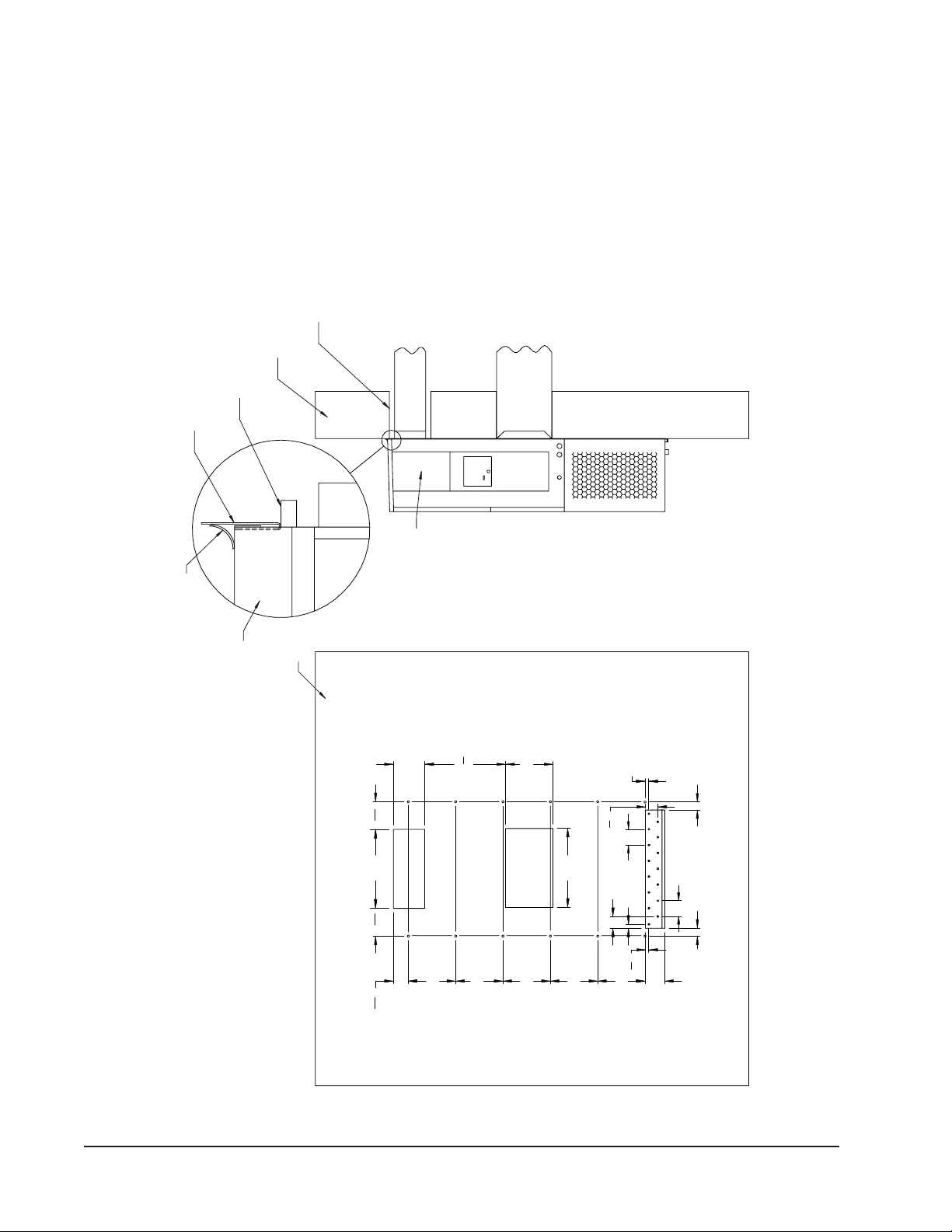
1/4" CLEARANCE ON ALL
FOUR SIDES OF SUPPLY
MIS-353 C
MATERIALS
AIR DUCT IS REQUIRED
FROM COMBUSTABLE
WALL STRUCTURE
FOAM AIR SEAL
SUPPLY AIR
HEATER ACCESS
FIGURE 3A
SEAL WITH BEAD
OF CAULKING ALONG
RAIN FLASHING
SUPPLIED
TOP
ENTIRE LENGTH OF TOP.
WALL
MOUNTING INSTRUCTIONS
W17A1, W17L1, W18A1, W18L1, W24A1, W24L1
"
1
16
DUCT
8"
NOTES:
THE SIDE MOUNTING FLANGES AND UNDER
SILICONE CAULKING BE PLACED BEHIND
IT IS RECOMMENDED THAT A BEAD OF
RETURN AIR
OPENING
CONTROLS AND HEATER ACCESS
W**A UNIT SHOWN, W**L UNIT
TOP FLASHING AT TIME OF INSTALLATION.
IS ON OPPOSITE (LEFT) SIDE.
Right Side View
PANEL
"
1
2
20
12"
1"
"
1
8
3
4"
Typ.
Manual 2100-508F
Page 8 of 25
20"
Supply Opening
" 7
1
16
7
12"
"
13
16
3
12"
12"
20"
Return Opening
12"
1"
4"
3"
"
7
8
12"
Typ.
2" 2"
Wall Opening and Hole Location View
5"
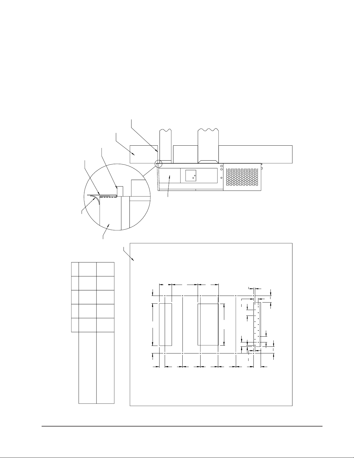
1/4" CLEARANCE ON ALL
FOUR SIDES OF SUPPLY
MIS-311 C
MATERIALS
AIR DUCT IS REQUIRED
FROM COMBUSTABLE
WALL STRUCTURE
FOAM AIR SEAL
RAIN FLASHING
SUPPLIED
FIGURE 3B
W30A1, W30L1, W36A1, W36L1
SEAL WITH BEAD
OF CAULKING ALONG
ENTIRE LENGTH OF TOP.
MOUNTING INSTRUCTIONS
EDCBA
17 5/83 13/165 1/48 1/228 1/2
TOP
16 7/84 9/164 1/21030
WALL
SUPPLY AIR
DUCT
PANEL
HEATER ACCESS
B
NOTES:
IT IS RECOMMENDED THAT A BEAD OF
SILICONE CAULKING BE PLACED BEHIND
THE SIDE MOUNTING FLANGES AND UNDER
TOP FLASHING AT TIME OF INSTALLATION.
W*R UNIT SHOWN, W*L UNIT
CONTROLS AND HEATER ACCESS
IS ON OPPOSITE (LEFT) SIDE.
RETURN AIR
OPENING
E
14"
1"
"
1
2
"
1
8
3
4"
Typ.
4
28"
Supply Opening
Return Opening
C CA
D
12"
12"
12"
1/4" MIN. CLEARANCE FROM
COMBUSTIBLE MATERIALS
REQUIRED DIMENSIONS TO MAINTAIN
COMBUSTIBLE MATERIALS
RECOMMENDED 1" CLEARANCE FROM
REQUIRED DIMENSIONS TO MAINTAIN
12"
1"
4"
3"
"
7
8
12"
Typ.
"
1
2
4
Wall Opening and Hole Location View Right Side View
5"
Manual 2100-508F
Page 9 of 25

FOAM AIR SEAL
SUPPLIED
RAIN FLASHING
FOUR SIDES OF SUPPLY
AIR DUCT IS REQUIRED
1/4" CLEARANCE ON ALL
WALL STRUCTURE
FROM COMBUSTABLE
MATERIALS
DUCT
SUPPLY AIR
PANEL
RETURN AIR
OPENING
W*R UNIT SHOWN, W*L UNIT
CONTROLS AND HEATER ACCESS
IT IS RECOMMENDED THAT A BEAD OF
SILICONE CAULKING BE PLACED BEHIND
TOP FLASHING AT TIME OF INSTALLATION.
THE SIDE MOUNTING FLANGES AND UNDER
NOTES:
IS ON OPPOSITE (LEFT) SIDE.
MIS-416 C
Right Side View
TOP.
FIGURE 3C
SEAL WITH BEAD
ENTIRE LENGTH OF
OF CAULKING ALONG
MOUNTING INSTRUCTIONS
TOP
29
2
6 1/4 1 1/4 29 3/4
W42A1, W42L1, W48A1, W48L1, W60A1, W60L1, W70A1, W70L1
10 1/2
ABCDE
30 1/2
32 12 5 1/2
WALL
CC
HEATER ACCESS
B
A
E
Supply Opening
D
16"
16"
16"
Return Opening
16"
"
7
8
"
1
8
3
4"
Typ.
"
1
8
2
"
1
2
30"
3"
1"
4"
Typ.
"
1
2
6
1
16"
1
16"
" 6
1
2
6
Dimension is 21" on W6R and W6L Units.
1
Wall Opening and Hole Location View
"
7
8
1
1 Dimension is 21" on W70A & W70L Units.
Manual 2100-508F
Page 10 of 25
1/4" MIN. CLEARANCE FROM
REQUIRED DIMENSIONS TO MAINTAIN
COMBUSTIBLE MATERIALS
REQUIRED DIMENSIONS TO MAINTAIN
RECOMMENDED 1" CLEARANCE FROM
COMBUSTIBLE MATERIALS

FIGURE 4
ELECTRIC HEAT CLEARANCE
W30A1, W30L1, W36A1, W36L1, W42A1, W42L1, W48A1, W48L1, W60A1, W60L1, W70A1, W70L1
SIDE SECTION VIEW OF SUPPLY AIR DUCT FOR
WALL MOUNTED UNIT SHOWING 1/4 INCH
CLEARANCE TO COMBUSTIBLE SURFACES.
WARNING
A minimum of 1/4 inch clearance must be maintained between
the supply air duct and combustible materials. This is required
for the first 3 feet of ducting.
It is important to insure that the 1/4 inch minimum spacing is
maintained at all points.
Failure to do this could result in overheating the combustible
material and may result in a fire causing damage, injury or death.
Manual 2100-508F
Page 11 of 25

FIGURE 5
WALL MOUNTING INSTRUCTIONS
SEE FIGURE 3 – MOUNTING INSTRUCTIONS
SUPPLY AIR
OPENING
RETURN AIR
OPENING
CONCRETE BLOCK WA LL INS T A LL A T I ON
SUPPLY AIR
OPENING
RETURN AIR
OPENING
WOOD OR STEEL SIDING
WOOD FRAME WALL INSTALLATION
FACTORY SUPPLIED
RAIN FLASHING.
MOUNT ON UNIT
BEFORE INSTALLATION
BOTTOM MOUNTING
BRACKET. MOUNT ON
WALL BEFORE
INSTALLING UNIT.
SIDE VIEW
WALL STRUCTURE
SUPPLY AIR
DUCT
RETURN AIR
OPENING
MIS-548 A
MIS-549 A
WALL MOUNTING INSTRUCTIONS
FRAMING MATERIAL
2 x 4'S, 2 x 6'S &/OR
STRUCTURAL STEEL
FIGURE 6
ATTACH TO TOP
PLATE OF WALL
1.000" CLEARANCE
ALL AROUND DUCT
IF REQUIRED
INTERIOR FINISHED WALL
OVER FRAME
1.000" CLEARANCE
ALL AROUND DUCT
IF REQUIRED
EXTERIOR FINISH WALL
OVER FRAME
ATTACH TO BOTTOM
PLATE OF WALL
SEE UNIT DIMENSIONS, FIGURE 2,
FOR ACTUAL DIMENSIONS.
E + 1.000
E + 1.000
E + 1.000
E + 1.000
E + 1.000
E + 1.000
E + 1.000
E + 1.000
E + 1.000
E + 1.000
E + 1.000
E + 1.000
E + 1.000
E + 1.000
E + 1.000
E + 1.000
E + 1.000
B
B
B
B
B
B
B
B
B
B
B
B
B
B
B
B
B
SUPPLY DUCT
OPENING
RETURN DUCT
OPENING
C
2 x 6
L
THIS STRUCTURAL MEMBER
LOCATED TO MATCH STUD
SPACING FOR REST OF WALL.
A SECOND MEMBER MAY BE
REQUIRED FOR SOME WALLS.
1.000
1.000
1.000
1.000
1.000
1.000
1.000
1.000
1.000
1.000
1.000
1.000
1.000
1.000
1.000
1.000
1.000
A
A
A
A
A
A
A
A
A
A
A
A
A
A
A
A
A
I
I
I
I
I
I
I
I
I
I
I
I
I
I
I
I
I
C
C
C
C
C
C
C
C
C
C
C
C
C
C
C
C
C
K
K
K
K
K
K
K
K
K
K
K
K
K
K
K
K
K
Manual 2100-508F
Page 12 of 25

FIGURE 7
COMMON WALL MOUNTING INSTALLATIONS
SUPPLY DUCT MAY BE LOCATED IN AN ATTIC
OR BELOW CEILING RAFTERS AS SHOWN
RAIN
FLASHING
OUTSIDE
WALL
RAIN
FLASHING
RAFTERS
FINISHED CEILING SURFACE
SUPPLY AIR DUCT
W/ GRILLE
RETURN AIR
OPENING W/ GRILLE
FREE AIR FLOW
SUPPLY DUCT MAYBE LOCATED IN AN ATTIC
OR BELOW CEILING RAFTERS AS SHOWN
RAFTERS
RAIN
FLASHING
OUTSIDE
WALL
RAIN
FLASHING
RAFTERS
SUPPLY AIR DUCT
FINISHED CEILING SURFACE
RETURN AIR
OPENING W/ GRILLE
DUCTED SUPPLY
RETURN AT UNIT NO DUCT
SUPPLY DUCT MAYBE LOCATED IN AN ATTIC
OR BELOW CEILING RAFTERS AS SHOWN
RAFTERS
SUPPLY AIR DUCT
OUTSIDE
WALL
FALSE WALL INSTALLATION
FINISHED
CEILING SURFACE
RETURN AIR
SPACE
WALL SLEEVE
FALSE WALL
RETURN AIR GRILLE
OUTSIDE
WALL
SUPPLY AIR DUCT
LOWERED
CEILING
CLOSET WALL
WALL
SLEEVE
RAISED FLOOR
RETURN AIR
SUPPLY AIR
GRILLE
FINISHED CEILING
CLOSET INSTALLATION
Manual 2100-508F
Page 13 of 25
SURFACE
RETURN AIR
GRILLE
MIS-550 B

WIRING – MAIN POWER
Refer to the unit rating plate for wire sizing information
and maximum fuse or “HACR” type circuit breaker
size. Each outdoor unit is marked with a “Minimum
Circuit Ampacity”. This means that the field wiring
used must be sized to carry that amount of current.
Depending on the installed KW of electric heat, there
may be two field power circuits required. If this is the
case, the unit serial plate will so indicate. All models
are suitable only for connection with copper wire. Each
unit and/or wiring diagram will be marked “Use Copper
Conductors Only”. These instructions must be adhered
to. Refer to the National Electrical Code (NEC) for
complete current carrying capacity data on the various
insulation grades of wiring material. All wiring must
conform to NEC and all local codes.
The electrical data lists fuse and wire sizes (75° C
copper) for all models including the most commonly
used heater sizes. Also shown are the number of field
power circuits required for the various models with
heaters.
The unit rating plate lists a “Maximum Time Delay
Relay Fuse” or “HACR” type circuit breaker that is to
be used with the equipment. The correct size must be
used for proper circuit protection and also to assure that
there will be no nuisance tripping due to the momentary
high starting current of the compressor motor.
WIRING – LOW VOLTAGE WIRING
230/208V, 1 phase and 3 phase equipment dual primary
voltage transformers. All equipment leaves the factory
wired on 240V tap. For 208V operation, reconnect from
240V to 208V tap. The acceptable operating voltage
range for the 240 and 208V taps are:
TAP RANGE
240 253 – 216
208 220 – 187
NOTE: The voltage should be measured at the field power
connection point in the unit and while the unit is
operating at full load (maximum amperage
operating condition).
For wiring size and connections, refer to Wiring Manual
2100-507.
The disconnect access door on this unit may be locked
to prevent unauthorized access to the disconnect. To
convert for the locking capability, bend the tab located
in the bottom left-hand corner of the disconnect opening
under the disconnect access panel straight out. This tab
will now line up with the slot in the door. When shut, a
padlock may be placed through the hole in the tab
preventing entry.
See “Start Up” section for important information on
three phase scroll compressor start ups.
See Tables 3 & 4 for Electrical Specifications.
Manual 2100-508F
Page 14 of 25

START UP
THESE UNITS REQUIRE R-410A
REFRIGERANT AND POLYOL
ESTER OIL.
GENERAL:
1. Use separate service equipment to avoid cross
contamination of oil and refrigerants.
2. Use recovery equipment rated for R-410A
refrigerant.
3. Use manifold gauges rated for R-410A (800 psi/250
psi low).
4. R-410A is a binary blend of HFC-32 and HFC-125.
5. R-410A is nearly azeotropic - similar to R-22 and
R-12. Although nearly azeotropic, charge with
liquid refrigerant.
6. R-410A operates at 40-70% higher pressure than
R-22, and systems designed for R-22 cannot
withstand this higher pressure.
7. R-410A has an ozone depletion potential of zero,
but must be reclaimed due to its global warming
potential.
8. R-410A compressors use polyolester oil.
9. Polyol Ester oil is hygroscopic; it will rapidly absorb
moisture and strongly hold this moisture in the oil.
10. A liquid line dryer must be used - even a deep
vacuum will not separate moisture from the oil.
11. Limit atmospheric exposure to 15 minutes.
12. If compressor removal is necessary, always plug
compressor immediately after removal. Purge with
small amount of nitrogen when inserting plugs.
TOPPING OFF SYSTEM CHARGE
If a leak has occurred in the system, Bard Manufacturing
recommends reclaiming, evacuating (see criteria above),
and charging to the nameplate charge. If done correctly,
topping off the system charge can be done without
problems.
With R-410A, there are no significant changes in the
refrigerant composition during multiple leaks and
recharges. R-410A refrigerant is close to being an
azeotropic blend (it behaves like a pure compound or
single component refrigerant). The remaining
refrigerant charge, in the system, may be used after
leaks have occurred and then “top-off” the charge by
utilizing the pressure charts on the inner control panel
cover as a guideline.
REMEMBER: When adding R-410A refrigerant, it
must come out of the charging cylinder/tank as a liquid
to avoid any fractionation, and to insure optimal system
performance. Refer to instructions for the cylinder that
is being utilized for proper method of liquid extraction.
WARNING
Failure to conform to these practices
could lead to damage, injury or death.
SAFETY PRACTICES:
1. Never mix R-410A with other refrigerants.
2. Use gloves and safety glasses, Polyol Ester oils can
be irritating to the skin, and liquid refrigerant will
freeze the skin.
3. Never use air and R-410A to leak check; the
mixture may become flammable.
4. Do not inhale R-410A – the vapor attacks the
nervous system, creating dizziness, loss of
coordination and slurred speech. Cardiac
irregularities, unconsciousness and ultimate death
can result from breathing this concentration.
5. Do not burn R-410A. This decomposition
produces hazardous vapors. Evacuate the area if
exposed.
6. Use only cylinders rated DOT4BA/4BW 400.
7. Never fill cylinders over 80% of total capacity.
8. Store cylinders in a cool area, out of direct
sunlight.
9. Never heat cylinders above 125°F.
10. Never trap liquid R-410A in manifold sets, gauge
lines or cylinders. R-410A expands significantly
at warmer temperatures. Once a cylinder or line is
full of liquid, any further rise in temperature will
cause it to burst.
Manual 2100-508F
Page 15 of 25

START UP (Continued)
IMPORTANT INSTALLER NOTE
For improved start up performance wash the indoor coil
with a dish washing detergent.
HIGH PRESSURE SWITCH
All W**A/W**L wall mounted air conditioner series
models are supplied with a remote reset for the high and
low pressure switch. If tripped, this pressure switch may
be reset by turning the thermostat off then back on again.
THREE PHASE SCROLL COMPRESSOR
START UP INFORMATION
Scroll compressors, like several other types of
compressors, will only compress in one rotational
direction. Direction of rotation is not an issue with
single phase compressors since they will always start
and run in the proper direction.
However, three phase compressors will rotate in either
direction depending upon phasing of the power. Since
there is a 50-50 chance of connecting power in such a
way as to cause rotation in the reverse direction,
verification of proper rotation must be made.
Verification of proper rotation direction is made by
observing that suction pressure drops and discharge
pressure rises when the compressor is energized.
Reverse rotation also results in an elevated sound level
over that with correct rotation, as well as substantially
reduced current draw compared to tabulated values.
Verification of proper rotation must be made at the
time the equipment is put into service. If improper
rotation is corrected at this time, there will be no
negative impact on the durability of the compressor.
However, reverse operation for over one hour may have
a negative impact on the bearing due to oil pump out.
NOTE: If compressor is allowed to run in reverse rotation
for several minutes, the compressor’s internal
protector will trip.
PHASE MONITOR
All units with three phase scroll compressors are
equipped with a 3 phase line monitor to prevent
compressor damage due to phase reversal.
The phase monitor in this unit is equipped with two
LEDs. If the Y signal is present at the phase monitor
and phases are correct the green LED will light.
If phases are reversed, the red fault LED will be lit and
compressor operation is inhibited.
If a fault condition occurs, reverse two of the supply
leads to the unit. Do not reverse any of the unit factory
wires as damage may occur.
CONDENSER FAN OPERATION
Applies to W42, W48, W60 and W70 models only. The
condenser fan motor on 230/208 volt, one and three
phase, 60 HZ units is a two-speed motor that comes
factory wired on high speed for peak performance. If
ambient conditions permit, it can be reconnected to low
speed (red wire) for lower sound level. See wiring
diagram.
50 HZ models must have fan wired on low speed.
These models are factory wired on low speed.
SERVICE HINTS
1. Caution owner/operator to maintain clean air filters
at all times. Also, not to needlessly close off supply
and return air registers. This reduces airflow
through the system, which shortens equipment
service life as well as increasing operating costs.
2. Check all power fuses or circuit breakers to be sure
they are the correct rating.
3. Periodic cleaning of the outdoor coil to permit full
and unrestricted airflow circulation is essential.
All three phase compressors are wired identically
internally. As a result, once the correct phasing is
determined for a specific system or installation,
connecting properly phased power leads to the same
Fusite terminal should maintain proper rotation
direction.
The direction of rotation of the compressor may be
changed by reversing any two line connections to the
unit.
Manual 2100-508F
Page 16 of 25

SEQUENCE OF OPERATION
COOLING – Circuit R-Y makes at thermostat pulling
in compressor contactor, starting the compressor and
outdoor motor. The G (indoor motor) circuit is
automatically completed on any call for cooling
operation or can be energized by manual fan switch on
subbase for constant air circulation. On a call for
heating, circuit R-W1 make at the thermostat pulling in
heat contact for the strip heat and blower operation. On
a call for second stage heat, R-W2 makes bringing on
second heat contactor, if so equipped.
COMPRESSOR CONTROL MODULE
The compressor control module is standard on all
models covered by this manual. The compressor control
module is an anti-short cycle/lockout timer with high
and low pressure switch monitoring and alarm relay
output.
Adjustable Delay On Make And Break Timer
On initial power up or anytime power is interrupted to
the unit, the delay on make period begins, which will be
2 minutes plus 10% of the delay on break setting. When
the delay on make is complete and the high pressure
switch and low pressure switch is closed, the compressor
contactor is energized. Upon shutdown, the delay on
break timer starts and prevents restart until the delay on
break and delay on make periods have expired.
During routine operation of the unit with no power
interruptions, the compressor will operate on demand
with no delay.
High Pressure Switch and Lockout Sequence
If the high pressure switch opens, the compressor
contactor will de-energize immediately. The lockout
timer will go into a soft lockout and stay in soft lockout
until the high pressure switch closes
break time has expired. If the high pressure switch
opens again in this same operating cycle, the unit will go
into manual lockout condition and the alarm relay circuit
will energize. Recycling the wall thermostat resets the
manual lockout.
Low Pressure Switch, Bypass, and Lockout
Sequence
If the low pressure switch opens for more than 120
seconds, the compressor contactor will de-energize and
go into a soft lockout. Regardless the state of the low
pressure switch, the contactor will reenergize after the
delay on make time delay has expired. If the low
pressure switch remains open, or opens again for longer
than 120 seconds, the unit will go into manual lockout
condition and the alarm relay circuit will energize.
Recycling the wall thermostat resets the manual lockout.
and the delay on
Alarm Relay Output
Alarm terminal is output connection for applications
where alarm relay is employed. This terminal is
powered whenever the compressor is locked out due to
HPC or LPC sequences as described.
NOTE: Both high and low pressure switch controls are
inherently automatic reset devices. The high
pressure switch and low pressure switch cut out
and cut in settings are fixed by specific air
conditioner unit model. The lockout features,
both soft and manual, are a function of the
Compressor Control Module.
ADJUSTMENTS
Adjustable Delay on Make and Delay on Break
Timer
The potentiometer is used to select Delay on Break time
from 30 seconds to 5 minutes. Delay on Make (DOM)
timing on power-up and after power interruptions is
equal to 2 minutes plus 10% of Delay on Break (DOB)
setting:
0.5 minute (30 seconds) DOB = 123 second DOM
1.0 minute (60 seconds) DOB = 126 second DOM
2.0 minute (120 seconds) DOB = 132 second DOM
3.0 minute (180 seconds) DOB = 138 second DOM
4.0 minute (240 seconds) DOB = 144 second DOM
5.0 minute (300 seconds) DOB = 150 second DOM
During routine operation of the unit with no power
interruptions the compressor will operate on demand
with no delay.
Typical Settings for Dual Unit Installation:
Unit 1: DOB set at 2 minutes, and DOM is 132 seconds
Unit 2: DOB set at 4 minutes, and DOM is 144 seconds
PRESSURE SERVICE PORTS
High and low pressure service ports are installed on all
units so that the system operating pressures can be
observed. A pressure table can be found later in the
manual covering all models. It is imperative to match
the correct pressure table to the unit by model number.
See Table 2.
Manual 2100-508F
Page 17 of 25

TROUBLESHOOTING
FAN BLADE SETTING DIMENSIONS
Shown in Figure 8 is the correct fan blade setting for
proper air delivery across the outdoor coil. Refer to
Table 1 for unit specific dimension.
Any service work requiring removal or adjustment in
the fan and/or motor area will require that the
dimensions below be checked and blade adjusted in or
out on the motor shaft accordingly.
FIGURE 8
FAN BLADE SETTING
MIS-1724
R-410A
REFRIGERANT CHARGE
This unit was charged at the factory with the quantity of
refrigerant listed on the serial plate. AHRI capacity and
efficiency ratings were determined by testing with this
refrigerant charge quantity.
The following pressure tables show nominal pressures
for the units. Since many installation specific situations
can affect the pressure readings, this information should
only be used by certified technicians as a guide for
evaluating proper system performance. They shall not
be used to adjust charge. If charge is in doubt, reclaim,
evacuate and recharge the unit to the serial plate charge.
REMOVAL OF FAN SHROUD
1. Disconnect all power to the unit.
2. Remove the screws holding both grilles, one on each
side of unit, and remove grilles.
3. Remove screws holding fan shroud to condenser and
bottom. Nine (9) screws.
4. Unwire condenser fan motor.
5. Slide complete motor, fan blade, and shroud
assembly out the left side of the unit.
TABLE 1
FAN BLADE DIMENSION
ledoM
1L71W/1A71W
1L81W/1A81W
1L42W/1A42W
1L03W/1A03W
1L63W/1A63W
1L24W/1A24W
1L84W/1A84W
1L06W/1A06W
1L07W/1A07W"57.
A
"00.1
"52.1
"57.1
6. Service motor/fan as needed.
7. Reverse steps to reinstall.
noisnemiD
Manual 2100-508F
Page 18 of 25

TABLE 2
COOLING PRESSURE TABLE
Air Temperature Entering Outdoor Coil °F
riAnruteR
ledoM
1A71W1L/
1L/1A81W
1L/1A42W
1L/1A03W
1L/1A63W
1L/1A24W
1L/1A84W
1L/1A06W
1L/1A07W
Low side pressure ± 4 PSIG
High side pressure ± 10 PSIG
Tables are based upon rated CFM (airflow) across the evaporator coil. If there is any doubt as to correct operating charge
being in the system, the charge should be removed, system evacuated and recharged to serial plate charge weight.
NOTE:
Pressure table based on high speed condenser fan operation. If condensing pressures appear elevated check
condenser fan wiring. See “Condenser Fan Operation”.
erutarepmeTerusserP5708580959001501011511021
BD.ged57
BW.ged26
BD.ged08
BW.ged76
BD.ged58
BW.ged27
BD.ged57
BW.ged26
BD.ged08
BW.ged76
BD.ged58
BW.ged27
BD.ged57
BW.ged26
BD.ged08
BW.ged76
BD.ged58
BW.ged27
BD.ged57
BW.ged26
BD.ged08
BW.ged76
BD.ged58
BW.ged27
BD.ged57
BW.ged26
BD.ged08
BW.ged76
BD.ged58
BW.ged27
BD.ged57
BW.ged26
BD.ged08
BW.ged76
BD.ged58
BW.ged27
BD.ged57
BW.ged26
BD.ged08
BW.ged76
BD.ged58
BW.ged27
BD.ged57
BW.ged26
BD.ged08
BW.ged76
BD.ged58
BW.ged27
ediSwoL
ediShgiH
ediSwoL
ediShgiH
ediSwoL
ediShgiH
ediSwoL
ediShgiH
ediSwoL
ediShgiH
ediSwoL
ediShgiH
ediSwoL
ediShgiH
ediSwoL
ediShgiH
ediSwoL
ediShgiH
ediSwoL
ediShgiH
ediSwoL
ediShgiH
ediSwoL
ediShgiH
ediSwoL
ediShgiH
ediSwoL
ediShgiH
ediSwoL
ediShgiH
ediSwoL
ediShgiH
ediSwoL
ediShgiH
ediSwoL
ediShgiH
ediSwoL
ediShgiH
ediSwoL
ediShgiH
ediSwoL
ediShgiH
ediSwoL
ediShgiH
ediSwoL
ediShgiH
ediSwoL
ediShgiH
721
592
631
303
141
413
121
623
921
433
431
643
121
533
921
443
431
653
321
053
231
953
731
273
821
143
731
053
241
263
521
943
431
853
931
173
621
253
531
163
041
473
811
623
621
433
031
643
921
613
831
423
341
533
321
053
231
953
731
273
221
753
131
663
631
973
521
273
431
283
931
593
031
263
931
173
441
483
721
073
631
973
141
293
821
373
731
383
241
693
911
743
721
653
131
863
131
733
041
643
541
853
521
573
431
583
931
893
521
083
431
093
931
404
721
693
631
604
024
231
383
393
641
704
921
831
341
514
031
693
931
604
441
024
073
921
973
431
293
331
063
241
963
741
283
721
104
631
114
141
524
721
404
631
414
141
824
921
024
831
134
141
341
644
331
604
141
241
614
741
134
193
104
121
131
514
041
624
541
144
231
814
141
924
641
444
221
293
131
204
631
614
531
383
541
004
941
704
031
624
731
441
254
031
924
931
634
441
554
544
041
254
541
274
531
924
241
534
941
554
331
044
241
454
741
764
331
244
241
354
741
964
321
614
231
724
731
244
731
704
641
714
151
234
231
054
134
131
141
264
641
874
231
454
141
664
641
284
331
074
241
284
741
994
731
354
641
564
151
184
631
764
541
974
051
694
531
664
441
874
941
594
521
044
431
154
931
764
831
234
841
344
351
954
431
774
341
984
841
605
431
184
341
394
841
015
631
694
541
905
051
725
831
084
841
294
351
905
731
594
741
805
251
625
731
194
641
405
151
225
721
564
631
774
141
494
041
754
051
964
551
584
531
205
441
515
941
335
631
905
541
225
051
045
831
425
841
735
351
655
041
605
051
915
551
735
041
625
051
935
551
855
731
715
741
035
251
945
031
984
931
205
441
025
Manual 2100-508F
Page 19 of 25
141
484
151
694
651
315
731
725
641
145
151
065
731
735
641
155
151
075
041
255
051
665
551
685
241
435
251
845
751
765
341
755
351
175
851
195
931
445
941
855
451
875
231
615
141
925
641
845
341
115
351
425
851
245
831
355
841
765
351
785
831
665
841
185
351
106
341
185
351
695
851
716
441
465
451
875
951
895
641
095
651
506
161
626
141
175
151
685
651
706
531
245
441
655
941
575

TABLE 3
Electrical Specifications — W**A Series
tiucriCelgniS tiucriClauD
ledoM
50A
80A
01A
Z0A,00A-1A42W
50A
80A
01A
Z0B,00B-1A42W
60B
Z0C,00C-1A42W
60C
*50A
80A
*01A
51A
60B
*90B
51B
60C
*90C
51C
*50A
80A
*01A
51A
60B
*90B
51B
60C
*90C
51C
Z0A,00A-1A24W
50A
01A
51A
02A
Z0B,00B-1A24W
90B
51B
81B
Z0C,00C-1A24W
90C
51C
Z0A,00A-1A84W
50A
01A
51A
02A
Z0B,00B-1A84W
90B
51B
81B
Z0C,00C-1A84W
90C
51C
Z0A,00A-1A06W
50A
01A
51A
02A
Z0B,00B-1A06W
90B
51B
81B
Z0C,00C-1A06W
90C
51C
Z0A,00A-1A07W
50A
01A
51A
02A
Z0B,00B-1A07W
90B
51B
81B
Z0C,00C-1A07W
90C
51C
detaR
stloV
esahPdna
Z0A,00A-1A81,71W
*Z0A,*00A-1A03W
*Z0B,*00B-1A03W
*Z0C,*00C-1A03W
*Z0A,*00A-1A63W
*Z0B,*00B-1A63W
*Z0C,*00C-1A63W
1-802/032
1-802/032
3-802/032
3-064
1-802/032
3-802/032
3-064
1-802/032
3-802/032
3-064
1-802/032
3-802/032
3-064
1-802/032
3-802/032
3-064
1-802/032
3-802/032
3-064
1-802/032
3-802/032
3-064
3 muminiM
dleiF.oN
rewoP
stiucriC
1
1
1
1
1
1
1
1
1
1
1
1
1
1
1
1
2ro1
1
1
1
1
1
1
1
1
1
1
1
1
2ro1
1
1
1
1
1
1
1
1
1
1
1
2ro1
2ro1
1
1
1
2
1
1
1
1
1
1
2ro1
2ro1
1
1
1
2
1
1
1
1
1
1
2ro1
2ro1
1
1
1
2
1
1
1
1
1
2ro1
2ro1
2ro1
1
1
1
2
1
1
1
1 mumixaM
tiucriC
yticapmA
61
03
64
65
12
03
64
65
51
22
01
21
42
23
84
85
48
81
42
33
15
11
21
71
62
92
23
84
85
48
32
42
33
15
21
21
71
62
33
33
95
58
111
52
43
35
A/N
31
81
72
73
73
95
58
111
92
43
25
A/N
41
81
72
14
14
95
58
111
82
43
35
A/N
51
81
72
94
94
95
58
111
34
34
35
A/N
32
32
72
02
03
05
06
03
03
05
06
51
52
51
51
53
53
05
06
09
02
52
53
06
51
51
02
03
53
53
05
06
09
03
03
53
06
51
51
02
03
05
05
06
09
53
53
06
A/N
51
02
03
05
05
06
09
04
04
06
A/N
02
02
03
06
06
06
09
04
04
06
A/N
02
02
03
06
06
06
09
06
06
06
A/N
03
03
53
2 dleiF
esuFlanretxE
.rkrB.tkCro
521
521
521
521
2 dnuorG
rewoP
eziSeriW
21
01
8
6
01
01
8
6
41
01
41
41
8
8
8
6
4
21
01
8
8
41
41
21
01
8
8
8
6
4
01
01
8
6
41
41
01
01
8
8
6
4
2
8
8
6
A/N
41
21
01
8
8
6
4
2
8
8
6
A/N
21
21
01
8
8
6
4
2
8
8
6
A/N
21
21
01
8
8
6
4
2
8
8
6
A/N
01
01
8
8856206036
8856206036
8
6
8
6
8
6
8
6
1 Maximum size of the time delay fuse or HACR type circuit breaker for protection of field wiring conductors.
2 Based on 75C copper wire. All wiring must conform to the National Electrical Code and all local codes.
3 These “Minimum Circuit Ampacity” values are to be used for sizing the field power conductors. Refer to the National Electrical code (latest version), Article
310 for power conductor sizing.
Caution: When more than one field power circuit is run through one conduit, the conductors must be derated. Pay special attention to note 8 of Table 310
regarding Ampacity Adjustment Factors when more than three (3) current carrying conductors are in a raceway.
* Top outlet supply option is available only factory installed and only on the selected models.
IMPORTANT: While this electrical data is presented as a guide, it is important to electrically connect properly sized fuses and conductor wires in
accordance with the National Electrical Code and all local codes.
Manual 2100-508F
Page 20 of 25
3 muminiM
eriW
21
01
01
01
01
01
01
01
41
01
41
41
01
01
01
01
21
01
01
01
41
41
21
01
01
01
01
01
01
01
01
01
41
41
01
01
01
01
01
01
01
01
A/N438253038
41
21
01
01
01
01
01
01
01
A/N438204038
21
21
01
01
01
01
01
01
01
A/N438204038
21
21
01
01
01
01
01
01
01
A/N348206038
01
01
01
A.tkCB.tkCA.tkCB.tkCA.tkCB.tkCA.tkCB.tkC
95
95
95
95
95
95
95
95
1 mumixaM
tiucriC
yticapmA
62
06
25
06
62
06
25
06
62
06
25
06
62
06
25
06
2 dleiF
esuFlanretxE
.rkrB.tkCro
03
6
06
6016
03
6
06
6016
03
6
06
6016
03
6
06
6016
2 dnuorG
rewoP
eziSeriW
010101
010101
01
01
010101
01
01
010101
01
01
010101
01
01
010101
eziSeriW
01
01
01
01
01
01
01
01

TABLE 4
Electrical Specifications — W**L Series
tiucriCelgniS tiucriClauD
ledoM
Z0A,00A-1L81,71W
50A
80A
01A
Z0A,00A-1L42W
50A
80A
01A
Z0B,00B-1L42W
60B
*Z0A,*00A-1L03W
*50A
80A
*01A
51A
*Z0B,*00B-1L03W
*90B
51B
*Z0C,*00C-1L03W
*90C
51C
*Z0A,*00A-1L63W
*50A
*01A
51A
*Z0B,*00B-1L63W
*90B
51B
*Z0C,*00C-1L63W
*90C
51C
Z0A,00A-1L24W
50A
01A
51A
Z0B,00B-1L24W
90B
51B
Z0C,00C-1L24W
90C
51C
Z0A,00A-1L84W
50A
01A
51A
Z0B,00B-1L84W
90B
51B
Z0C,00C-1L84W
90C
51C
Z0A,00A-1L06W
50A
01A
51A
Z0B,00B-1L06W
90B
51B
Z0C,00C-1L06W
90C
51C
Z0A-1L07W
50A
01A
51A
Z0B-1L07W
90B
51B
Z0C-1L07W
90C
51C
detaR
stloV
esahPdna
1-802/032
1-802/032
3-802/032
1-802/032
3-802/032
3-064
1-802/032
3-802/032
3-064
1-802/032
3-802/032
3-064
1-802/032
3-802/032
3-064
1-802/032
3-802/032
3-064
1-802/032
3-802/032
3-064
3 muminiM
dleiF.oN
rewoP
stiucriC
1
1
1
1
1
1
1
1
1
1
1
1
1
1
2ro1
1
1
1
1
1
1
1
1
1
2ro1
1
1
1
1
1
1
1
1
1
2ro1
1
1
1
1
1
1
1
1
1
2ro1
1
1
1
1
1
1
1
1
1
2ro1
1
1
1
1
1
1
1
1
2ro1
2ro1
1
1
1
1
1
1
1 mumixaM
tiucriC
yticapmA
61
03
64
65
12
03
64
65
51
22
42
23
84
85
48
81
33
15
11
71
62
92
23
85
48
32
33
15
21
71
62
33
33
95
58
52
43
35
31
81
72
73
73
95
58
92
43
25
41
81
72
14
14
95
58
82
43
35
51
81
72
94
94
95
58
34
34
35
32
32
72
02
03
05
06
03
03
05
06
51
52
53
53
05
06
09
02
53
06
51
02
03
53
53
06
09
03
53
06
51
02
03
05
05
06
09
53
53
06
51
02
03
05
05
06
09
04
04
06
02
02
03
06
06
06
09
04
04
06
02
02
03
06
06
06
09
06
06
06
03
03
53
2 dleiF
esuFlanretxE
.rkrB.tkCro
8
6
8
6
8
8
8
6
4
8
8
8
8
6
4
8
6
8
8
6
4
8
8
6
8
8
6
4
8
8
6
8
8
6
4
8
8
6
8
8
6
4
8
8
6
8
2 dnuorG
rewoP
eziSeriW
21
01
01
01
41
01
21
41
21
01
01
41
01
01
41
21
01
21
21
01
21
21
01
01
01
21
01
01
01
01
01
01
01
41
01
01
01
01
01
8856206036
21
01
01
41
21
01
01
01
01
8856206036
01
01
01
41
01
01
01
01
01
8956206036
01
01
01
41
21
01
01
01
01
8956206036
01
01
01
21
21
01
01
01
01
8956206036
01
01
01
21
21
01
01
01
01
8956206036
01
01
01
01
01
01
1 Maximum size of the time delay fuse or HACR type circuit breaker for protection of field wiring conductors.
2 Based on 75C copper wire. All wiring must conform to the National Electrical Code and all local codes.
3 These “Minimum Circuit Ampacity” values are to be used for sizing the field power conductors. Refer to the National Electrical code (latest version), Article
310 for power conductor sizing.
Caution: When more than one field power circuit is run through one conduit, the conductors must be derated. Pay special attention to note 8 of Table 310
regarding Ampacity Adjustment Factors when more than three (3) current carrying conductors are in a raceway.
* Top outlet supply option is available only factory installed and only on the selected models.
IMPORTANT: While this electrical data is presented as a guide, it is important to electrically connect properly sized fuses and conductor wires in
accordance with the National Electrical Code and all local codes.
3 muminiM
eriW
A.tkCB.tkCA.tkCB.tkCA.tkCB.tkCA.tkCB.tkC
1 mumixaM
tiucriC
yticapmA
2 dleiF
esuFlanretxE
.rkrB.tkCro
rewoP
2 dnuorG
eziSeriW
010101
010101
010101
010101
010101
010101
eziSeriW
Manual 2100-508F
Page 21 of 25

TABLE 5
RECOMMENDED AIRFLOW
detaR
ledoM
L71W,A71W
L81W,A81W
L42W,A42W00802.059-007hgiH
L03W,A03W000104.0031-039hgiH
L63W,A63W001103.0531-039hgiH
L24W,A24W004103.0511-0061hgiH
L84W,A84W055102.5821-0571hgiH
L06W,A06W056103.5731-0591hgiH
L07W,A07W008102.5741-0002hgiH
* Rated CFM and ESP on high speed tap.
*MFC
05504.527-575hgiH
detaR
*PSE
dednemmoceR
egnaRwolfriA
deepSyrotcaF
noitcennoC
TABLE 6
INDOOR BLOWER PERFORMANCE
,L/A71W
,L/A81W
L/A42W
.P.S.E
nI
O
H
2
yrD
0.
1.
2.
3.
4.
5.
069
568
028
537
516
deepShgiHdeepShgiHdeepSwoLdeepShgiHdeepSwoLdeepShgiHdeepSwoL
teW
yrD
lioC
0201
lioC
579
509
008
537
056
535
5931
0431
5821
5021
0111
5001
teW
lioC
lioC
5131
0721
0911
0011
0001
078
L/A63W,L/A03WL/A84W,L/A24WL/A07W,L/A06W
yrD
059
039
019
558
008
—
teW
yrD
lioC
lioC
539
519
588
038
557
—
teW
yrD
lioC
5881
0771
5361
0051
0731
0521
lioC
0081
5661
0451
0041
5821
0511
—
lioC
0561
0551
0541
0531
0031
—
teW
yrD
lioC
0061
0051
0041
0031
5711
0022
0012
0002
5781
5771
0561
teW
yrD
lioC
lioC
0002
0091
0081
0071
0061
5741
0061
5251
—
—
—
—
teW
lioC
lioC
0541
5731
—
—
—
—
ledoM
teltuOTNORFTNORFPOTTNORFTNORF
deepSelgniShgiHwoLhgiHwoLhgiHwoLhgiHwoL
Z0A40A50A80A01A51A02A-
Z0B60B90B51B81B-
Z0C60C90C51C-
Values shown are for units equipped with standard 1-inch throwaway filter or 1-inch washable filter.
Derate ESP by .15 for 2-inch pleated filters.
Manual 2100-508F
Page 22 of 25
TABLE 7
MAXIMUM ESP OF OPERATION
ELECTRIC HEAT ONLY
,L/A71W
L/A42W,L/A81W
05.
05.
05.
05.
05.
05.
05.
05.
05.
04.
05.
05.
05.
54.
05.
05.
05.
54.
05.
05.
05.
54.
53.
05.
04.
05.
03.
05.
05.
04.
53.
L/A63W,L/A03WL/A84W,L/A24WL/A07W,L/A06W
05.
05.
05.
05.
54.
05.
54.
05.
54.
53.
05.
04.
05.
04.
05.
05.
05.
05.
05.
05.
05.
05.
05.
05.
05.
05.
05.
05.
05.
05.
54.
05.
05.
05.
05.
05.
05.
05.
05.
05.
05.
05.
05.
05.
05.
05.
05.
05.
05.
05.
05.
05.
05.
05.
04.
05.
05.
05.
05.
05.
05.
05.

TABLE 8
ELECTRIC HEAT
sledoM1-V0421-V8023-V0423-V8023-V064
WKspmAHUTBspmAHUTBspmAHUTBspmAHUTBspmAHUTB
47.61056314.4104201
58.02560711.8100821
64.41005025.21063512.700502
83.33003728.8257402
97.12006037.81030328.0100703
016.14031432.6300652
21 4.4105904
515.26052150.45004832.63002152.13004830.8100215
813.34034165.7300164
022.38062861.2700215
Manual 2100-508F
Page 23 of 25

rebmuNtraP
W17/18A1-A
W24A1-A
W24A1-B
50A-20AWHEXX
80A-A20WHEXX
01A-A20AWHEXX
60B-42AWHEX
60C-B42HWHEX
50A-30AWHEXX
80A-30AWHEXX
01A-30AWHEXX
51A-30AWHEXX
60B-30AWHEX
60B-A63WHEX
90B-30AWHEX
51B-73AWHEXX
60C-A30CWHEXX
90C-A30CWHEXX
HEATER KITS
PULL DISCONNECT (WMPD)
CIRCUIT BREAKER (WMCB) &
51C-A30AWHEXX
50A-50AWHEXX
01A-50AWHE XXXX
51A-50AWHE
02A-50AWHE XXXX
90B-50AWHEXX
51B-50AWHE XXXX
81B-A50WHE XXXX
90C-A50AWHE XXXX
51C-A50AWHE XXXX
50A-06AWHE XX
90B-06AWHE XX
B10-BCMWX
A20-BCMWX
B20-BCMWX
A30-BCMWX
B40-BCMWX
A50-BCMWX
B50-BCMWXX
B60-BCMW X
A80-BCMWXX
A90-BCMW XX
C10-DPMW XXXXXXX
B90-BCMW X
TABLE 9
OPTIONAL ACCESSORIES
W24A1-C
W30A1-A
W30A1-B
W30A1-C
W36A1-A
W36A1-B
W36A1-C
W42A1-A
X
XXXX
X
W42A1-B
W42A1-C
W48A1-A
W48A1-B
W48A1-C
W60A1-A
W60A1-B
W60A1-C
W70A1-A
W70A1-B
W70A1-C
Manual 2100-508F
Page 24 of 25

TABLE 10
VENT & CONTROL OPTIONS
rebmuNtraPnoitpircseD
41-CMCTDO XXX
51-CMC)esahP-1V032(tiKtratS XXX
32-CMCCDDXX
42-CMCCDDX
82-CMCCAL XXX
2-DAFBdradnatS-repmaDriAhserFcirtemoraBX
2-POBetalPffOknalBX
2-DAFMrepmaDriAhserFdezirotoMX
2-VRCnruteRgnirpS-rotalitneVlaicremmoCX
B2-MFIErezimonocEX
A2-FVREtloV032-rotalitneVyrevoceRygrenEX
3-DAFBdradnatS-repmaDriAhserFcirtemoraBX
3-POBetalPffOknalBX
3-DAFMrepmaDriAhserFdezirotoMX
3-SVRCnruteRgnirpS-rotalitneVlaicremmoCX
3-PVRCnruteRrewoP-rotalitneVlaicremmoCX
C3-MFIErezimonocEX
A3-FVREtloV032-rotalitneVyrevoceRygrenEX
C3-FVREtloV064-rotalitneVyrevoceRygrenEX
5-DAFBdradnatS-repmaDriAhserFcirtemoraBX
5-POBetalPffOknalBX
5-DAFMrepmaDriAhserFdezirotoMX
5-SVRCnruteRgnirpS-rotalitneVlaicremmoCX
5-PVRCnruteRrewoP-rotalitneVlaicremmoCX
C5-MFIErezimonocEX
A5-FVREtloV032-rotalitneVyrevoceRygrenEX
C5-FVREtloV064-rotalitneVyrevoceRygrenEX
W17, W18, W24
W30, W36
W42, W48, W60, W70
Manual 2100-508F
Page 25 of 25
 Loading...