

Page 1
INSTALLATION INSTRUCTIONS
WALL MOUNTED PACKAGE
HEAT PUMP
Models:
W18H2-A W24H2-A
W24H2-B
W24H2-C
W30H2-A
W30H2-B
W30H2-C
W36H2-A
W36H2-B
W36H2-C
W42H2-A
W42H2-B
W42H2-C
W48H2-A
W48H2-B
W48H2-C
W60H2-A
W60H2-B
W60H2-C
W24H2DA
W24H2DB
W24H2DC
W30H2DA
W30H2DB
W30H2DC
W36H2DA
W36H2DB
W36H2DC
W42H2DA
W42H2DB
W42H2DC
W48H2DA
W48H2DB
W48H2DC
W60H2DA
W60H2DB
W60H2DC
Bard Manufacturing Company, Inc.
Bryan, Ohio 43506
www.bardhvac.com
Manual: 2100-604B
Supersedes: 2100-604A
Date: 10-18-16
Page 1 of 28
Page 2

CONTENTS
Getting Other Information and Publications .... 3
Wall Mount General Information .........................4
Wall Mount Model Nomenclature .......................... 4
Shipping Damage ................................................ 4
General .............................................................. 4
Duct Work ........................................................... 5
Filters................................................................. 5
Fresh Air Intake ................................................... 5
Condensate Drain ................................................ 5
Installation ............................................................... 6
Wall Mounting Information ................................... 6
Mounting the Unit ............................................... 6
Clearances Required ............................................ 6
Minimum Clearances ........................................... 6
Wiring – Main Power .......................................... 14
Wiring – Low Voltage Wiring ................................ 14
Figures
Figure 1 Fresh Air Damper Assembly.................... 5
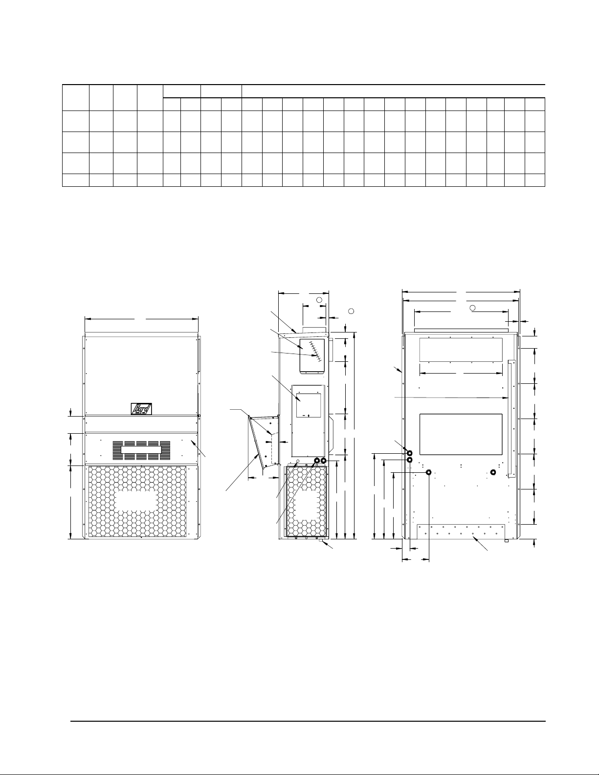
Figure 2 Unit Dimensions ................................... 7
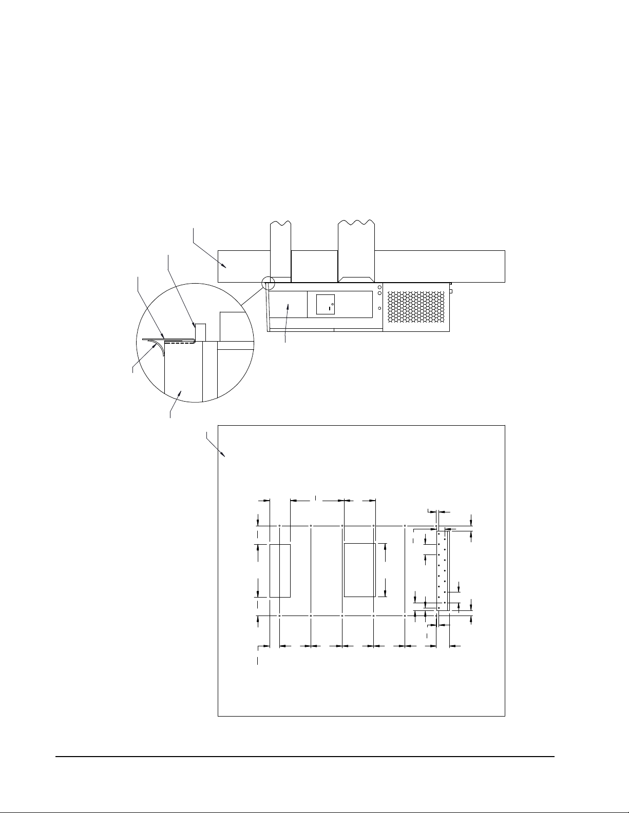
Figure 3A Mounting Instructions W18, W24 ........... 8
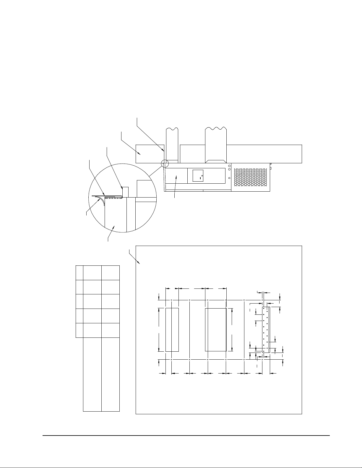
Figure 3B Mounting Instructions W30, W36 ........... 9
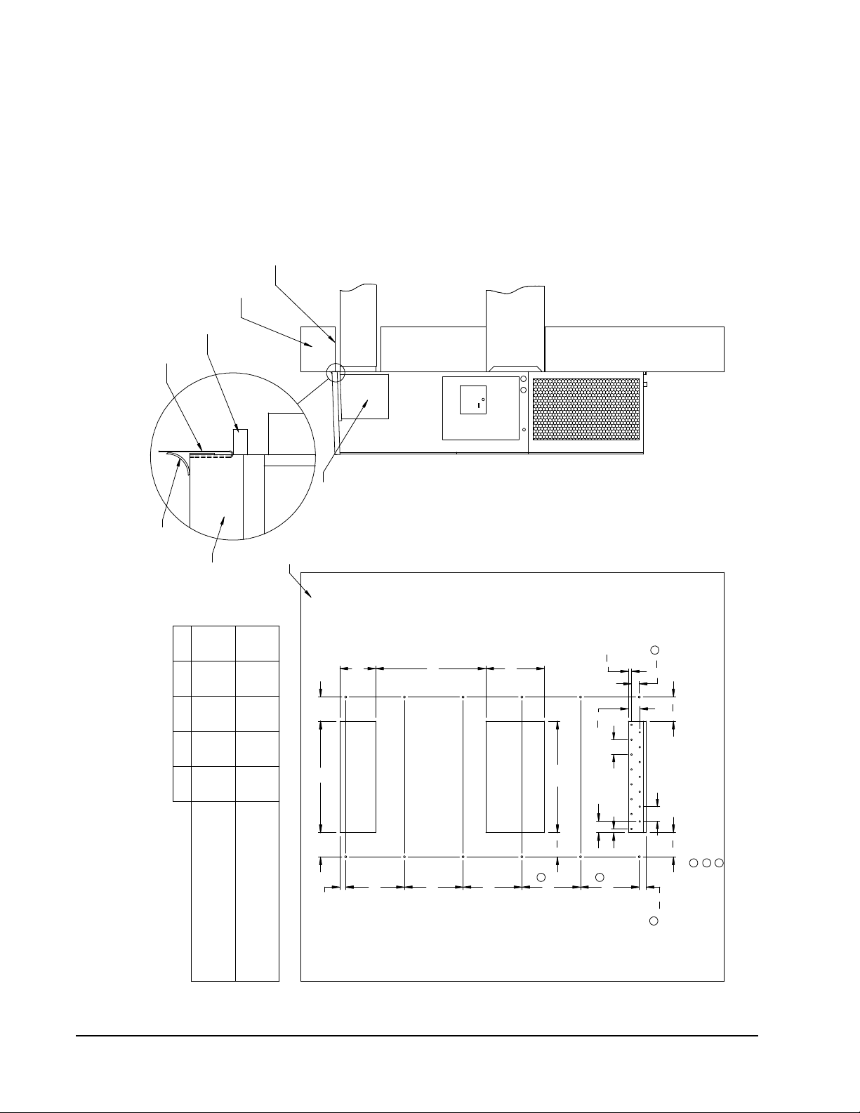
Figure 3C
Figure 4 Electric Heat Clearance ....................... 11
Figure 5 Wall Mounting Instructions .................. 12
Figure 6 Wall Mounting Instructions .................. 12
Figure 7 Common Wall Mounting Installations .... 13
Figure 8 Defrost Control Board .......................... 18
Figure 9 Fan Blade Setting ............................... 21
Mounting Instructions W42, W48, W60
.. 10
Start Up ................................................................... 15
General ............................................................ 15
Topping Off System Charge ................................. 15
Safety Practices ................................................ 15
Important Installer Note ..................................... 16
High and Low Pressure Switch ............................ 16
Three Phase Scroll Compressor ........................... 16
Phase Monitor ................................................... 16
Condenser Fan Operation ................................... 16
Service Hints .................................................... 16
Sequence of Operation ....................................... 16
Pressure Service Ports ........................................ 17
Defrost Cycle ..................................................... 17
Service ..................................................................... 19
Solid State Heat Pump Control ........................... 19
Checking Temperature Sensor ............................. 20
Fan Blade Setting Dimensions ............................ 21
Removal of Fan Shroud ...................................... 21
Refrigerant Charge ............................................. 21
Tables
Table 1 Troubleshooting .................................. 19
Temperature vs. Resistance ................................ 20
Table 2 Fan Blade Dimension .......................... 21
Table 3A Cooling Pressure ................................. 22
Table 3B Heating Pressure ................................. 22
Table 4A Electrical Specifications ...................... 23
Table 4B Electrical Specifications ...................... 24
Table 5 Recommended Airflow ......................... 25
Table 6 Indoor Blower Performance .................. 25
Tables 7 Maximum ESP Electric Heat Only ......... 26
Table 8 Electric Heat ...................................... 26
Table 9 Optional Accessories ........................... 27
Table 10 Vent and Control Options ..................... 28
Manual 2100-604B
Page 2 of 28
Page 3

GETTING OTHER INFORMATION AND PUBLICATIONS
These publications can help when installing the
furnace. They can usually be found at the local library
or purchased directly from the publisher. Be sure to
consult the current edition of each standard.
National Electrical Code ...................... ANSI/NFPA 70
Standard for the Installation ..............ANSI/NFPA 90A
of Air Conditioning and Ventilating Systems
Standard for Warm Air .......................ANSI/NFPA 90B
Heating and Air Conditioning Systems
Load Calculation for ......................... ACCA Manual J
Residential Winter and Summer Air Conditioning
Duct Design for Residential ............... ACCA Manual D
Winter and Summer Air Conditioning and Equipment
Selection
For more information, contact these publishers:
ACCA Air Conditioning Contractors of America
1712 New Hampshire Ave. N.W.
Washington, DC 20009
Telephone: (202) 483-9370
Fax: (202) 234-4721
ANSI American National Standards Institute
11 West Street, 13th Floor
New York, NY 10036
Telephone: (212) 642-4900
Fax: (212) 302-1286
ASHRAE American Society of Heating, Refrigeration
and Air Conditioning Engineers, Inc.
1791 Tullie Circle, N.E.
Atlanta, GA 30329-2305
Telephone: (404) 636-8400
Fax: (404) 321-5478
NFPA National Fire Protection Association
Batterymarch Park
P.O. Box 9101
Quincy, MA 02269-9901
Telephone: (800) 344-3555
Fax: (617) 984-7057
Manual 2100-604B
Page 3 of 28
Page 4
WALL MOUNT GENERAL INFORMATION
HEAT PUMP WALL MOUNT MODEL NOMENCLATURE
W 42 H 2 – A 10 X X X X X A
MODEL NUMBER
CAPACITY
18 - 1½ Ton
24 - 2 Ton
30 - 2½ Ton
36 - 3 Ton
42 - 3½ Ton
48 - 4 Ton
60 - 5 Ton
For 0 KW and circuit breakers (230/208 volt) or toggle disconnect (460V) applications, insert 0Z in the KW field of the model number.
Insert “D” for dehumidification with hot gas reheat. Reference Form 7960-702 for complete details.
NOTE: Vent options X, B and M are without exhaust capability. May require separate field-supplied barometric relief in building.
H - Heat Pump
SPECIALTY PRODUCTS
(Non-Standard)
VENTILATION OPTIONS
X - Barometric Fresh Air Damper (Standard)
B - Blank-off Plate
M - Motorized Fresh Air Damper
V - Commercial Ventilator - Motorized with Exhaust
S - Economizer (Std.) - Enthalpy
W - Economizer (Full Flow) - Enthalpy
T - Economizer (Full Flow) - Temperature
R - Energy Recovery Ventilator - Motorized with Exhaust
(See Spec. Sheet S3398)
SHIPPING DAMAGE
Upon receipt of equipment, the carton should be
checked for external signs of shipping damage. If
damage is found, the receiving party must contact
the last carrier immediately, preferably in writing,
requesting inspection by the carrier’s agent.
REVISIONS
VOLTS & PHASE
A - 230/208/60/1
B - 230/208/60/3
C - 460/60/3
KW
COLOR OPTIONS
X - Beige (Standard)
1 - White
4 - Buckeye Gray
5 - Desert Brown
8 - Dark Bronze
FILTER OPTIONS
X - 1" Throwaway (Standard)
W - 2" Washable
P - 2" Pleated
OUTLET OPTIONS
X - Front (Standard)
T - Top Outlet (W30H, W36H Only)
These instructions and any instructions packaged with
any separate equipment required to make up the entire
air conditioning system should be carefully read before
beginning the installation. Note particularly “Starting
Procedure” and any tags and/or labels attached to the
equipment.
CONTROL MODULES
(See Spec. Sheet S3398)
COIL OPTIONS
X - Standard
1 - Phenolic Coated Evaporator
2 - Phenolic Coated Condenser
3 - Phenolic Coated Evaporator
and Condenser
While these instructions are intended as a general
GENERAL
recommended guide, they do not supersede any
national and/or local codes in any way. Authorities
The equipment covered in this manual is to be installed
by trained, experienced service and installation
technicians.
The refrigerant system is completely assembled and
charged. All internal wiring is complete.
The unit is designed for use with or without duct work.
Flanges are provided for attaching the supply and
return ducts.
These instructions explain the recommended method
to install the air cooled self-contained unit and the
electrical wiring connections to the unit.
having jurisdiction should be consulted before the
installation is made. See page 3 for information on
codes and standards.
Size of unit for a proposed installation should be
based on heat loss/gain calculation made according
to methods of Air Conditioning Contractors of America
(ACCA). The air duct should be installed in accordance
with the Standards of the National Fire Protection
Association for the Installation of Air Conditioning and
Ventilating Systems of Other Than Residence Type,
NFPA No. 90A, and Residence Type Warm Air Heating
and Air Conditioning Systems, NFPA No. 90B. Where
local regulations are at a variance with instructions,
installer should adhere to local codes.
Manual 2100-604B
Page 4 of 28
Page 5
DUCT WORK
FILTERS
All duct work, supply and return, must be properly
sized for the design airflow requirement of the
equipment. Air Conditioning Contractors of America
(ACCA) is an excellent guide to proper sizing. All duct
work or portions thereof not in the conditioned space
should be properly insulated in order to both conserve
energy and prevent condensation or moisture damage.
Refer to Maximum ESP of operation Electric Heat
Tables 7.
Design the duct work according to methods given by
the Air Conditioning Contractors of America (ACCA).
When duct runs through unheated spaces, it should
be insulated with a minimum of 1" of insulation. Use
insulation with a vapor barrier on the outside of the
insulation. Flexible joints should be used to connect
the duct work to the equipment in order to keep the
noise transmission to a minimum.
Models W18 and W24 are approved for 0" clearance
to the supply duct. For model series W30, W36,
W42, W48 and W60, a 1/4" clearance to combustible
material for the first 3' of duct attached to the outlet air
frame is required. See Wall Mounting Instructions and
Figures 3 and 4 for further details.
Ducts through the walls must be insulated and all joints
taped or sealed to prevent air or moisture entering the
wall cavity.
Some installations may not require any return air duct.
A metallic return air grille is required with installations
not requiring a return air duct. The spacing between
louvers on the grille shall not be larger than 5/8".
Any grille that meets with 5/8" louver criteria may be
used. It is recommended that Bard Return Air Grille
Kit RG-2W through RG-5W or RFG-2W through RFG5W be installed when no return duct is used. Contact
distributor or factory for ordering information. If using
a return air filter grille, filters must be of sufficient size
to allow a maximum velocity of 400 fpm.
NOTE: If no return air duct is used, applicable
installation codes may limit this cabinet to
installation only in a single story structure.
A 1" throwaway filter is standard with each unit. The
filter slides into position making it easy to service. This
filter can be serviced from the outside by removing the
filter access panel. A 1" washable filter and 2" pleated
filter are also available as optional accessories. The
internal filter brackets are adjustable to accommodate
the 2" filter by bending two tabs down on each side of
the filter support bracket.
FRESH AIR INTAKE
All units are built with fresh air inlet slots punched in
the service door.
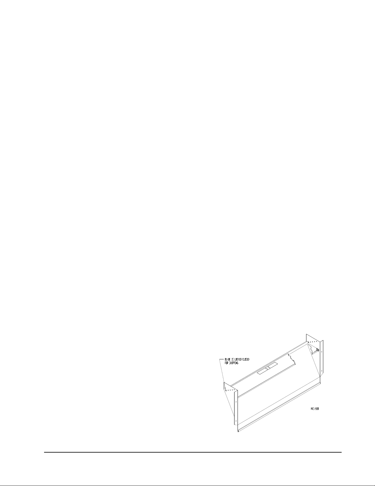
If the unit is equipped with a fresh air damper
assembly, the assembly is shipped already attached
to the unit. The damper blade is locked in the
closed position. To allow the damper to operate, the
maximum and minimum blade position stops must be
installed (see Figure 1).
All capacity, efficiency and cost of operation
information is based upon the fresh air blank-off plate
in place and is recommended for maximum energy
efficiency.
The blank-off plate is available upon request from the
factory and is installed in place of the fresh air damper
shipped with each unit.
CONDENSATE DRAIN
A plastic drain hose extends from the drain pan at
the top of the unit down to the unit base. There are
openings in the unit base for the drain hose to pass
through. In the event the drain hose is connected to
a drain system of some type, it must be an open or
vented type system to assure proper drainage.
FIGURE 1
Fresh Air Damper
Manual 2100-604B
Page 5 of 28
Page 6
INSTALLATION
WALL MOUNTING INFORMATION
1. Two holes for the supply and return air openings
must be cut through the wall as shown in Figure 3.
2. On wood frame walls, the wall construction must
be strong and rigid enough to carry the weight of
the unit without transmitting any unit vibration.
3. Concrete block walls must be thoroughly inspected
to insure that they are capable of carrying the
weight of the installed unit.
MOUNTING THE UNIT
WARNING
Failure to provide the 1/4" clearance between
the supply duct and a combustible surface
for the rst 3ʹ of duct can result in re causing
damage, injury or death.
1. These units are secured by wall mounting brackets
which secure the unit to the outside wall surface at
both sides. A bottom mounting bracket, attached
to skid for shipping, is provided for ease of
installation, but is not required.
2. The unit itself is suitable for 0" clearance, but the
supply air duct flange and the first 3' of supply
air duct require a minimum of 1/4" clearance to
combustible material for model series W30, W36,
W42, W48 and W60. However, it is generally
recommended that a 1" clearance is used for
ease of installation and maintaining the required
clearance to combustible material. See Figure 3
for details on opening sizes.
3. Locate and mark lag bolt locations and bottom
mounting bracket location (see Figure 3).
4. Mount bottom mounting bracket.
5. Hook top rain flashing, attached to front-right of
supply flange for shipping, under back bend of top.
Clearances Required for Service Access
and Adequate Condenser Airflow
MODELS LEFT SIDE RIGHT SIDE
W18H, W24H, W30H, W36H 15" 20"
W42H, W48H, W60H 20" 20"
6. Position unit in opening and secure with 5/16" lag
bolts; use 7/8" diameter flat washers on the lag
bolts.
7. Secure rain flashing to wall and caulk across entire
length of top (see Figure 3).
8. For additional mounting rigidity, the return air
and supply air frames or collars can be drilled
and screwed or welded to the structural wall itself
(depending upon wall construction). Be sure to
observe required clearance if combustible wall.
9. On side-by-side installations, maintain a minimum
of 20" clearance on right side to allow access to
control panel and heat strips, and to allow proper
airflow to the outdoor coil. Additional clearance
may be required to meet local or national codes.
NOTE: Refer to Figures 2 – 7 for dimensions and
various mounting configurations.
Minimum Clearances Required to
Combustible Materials
MODELS
W18H, W24H 0" 0"
W30H, W36H 1/4" 0"
W42H, W48H, W60H 1/4" 0"
SUPPLY AIR DUCT
FIRST 3'
CABINET
Manual 2100-604B
Page 6 of 28
Page 7
3"
11"
7.88
1.00
31.88
Heat
models.
Electric
Hood for
ECONWMT
MIS-2487 G
1
1
1
Condenser
Filter Access Panel
Front View
Air Outlet
Standard
flush vent
door for
non-ERV/
Econ.
models
Ventilation Air
5.88
F
W
G
Low Voltage
Electrical
Entrance
High Voltage
Side View
Drain
Electrical
Cond.
Air
Inlet
Heater
Access
Panel
4° Pitch
Built In
Rain Hood
Disconnect
Access Panel
(Lockable)
Entrance
C. Breaker/
Hood for ERV and
ECONWMS models
only
C
I
D
J
H
A
2.13
K
Mounting
Supply Air Opening
Side Wall
Brackets
Location
Shipping
Return Air Opening
(Built In)
Optional
Electrical
Entrances
Top Rain
Flashing
Bottom Installation
Bracket
Back View
P
M
O
E
R
S
S
S
S
S
T
.44
N
Q
B
L
FIGURE 2
Dimensions of Basic Unit for Architectural and Installation Requirements (Nominal)
Width
Depth
Model
(W)
W18H2
33.300 17.125 70.563 7.88 19.88 11.88 19.88 35.00 18.50 25.75 20.56 26.75 28.06 29.25 27.00 2.63 34.13 22.06 10.55 5.00 12.00 5.00
W24H2
W30H2
38.200 17.125 70.563 7.88 27.88 13.88 27.88 40.00 18.50 25.75 17.93 26.75 28.75 29.25 27.00 2.63 39.13 22.75 9.14 5.00 12.00 5.00
W36H2
W42H2
42.075 22.432 84.875 9.88 29.88 15.88 29.88 43.88 19.10 31.66 30.00 32.68 26.94 34.69 32.43 3.37 43.00 23.88 10.00 1.44 16.00 1.88
W48H2
W60H2 42.075 22.432 94.875 9.88 29.88 15.88 29.88 43.88 13.56 41.66 30.00 42.68 36.94 44.69 42.43 3.37 43.00 33.88 10.00 1.44 16.00 1.88
Height
(D)
All dimensions are in inches. Dimensional drawings are not to scale.
Supply Return
(H)
A B C B E F G I J K L M N O P Q R S T
W**H
RIGHT
UNIT
Optional top outlet (factory installed only) for W30H and W36H models only.
Manual 2100-604B
Page 7 of 28
Page 8
12"
12"
12"
1"
12"
20"
20"
"
3"
4"
Typ.
8"
20
1
2
"
12"
1"
3
1
8
"
4"
Typ.
5"
7
8
"
3
13
16
"
2" 2"
7
1
16
" 7
1
16
12"
Right Side View
RETURN AIR
DUCT
IS ON OPPOSITE (LEFT) SIDE.
OPENING
ENTIRE LENGTH OF TOP.
TOP
WALL
OF CAULKING ALONG
PANEL
FOAM AIR SEAL
WALL STRUCTURE
NOTES:
RAIN FLASHING
HEATER ACCESS
TOP FLASHING AT TIME OF INSTALLATION.
THE SIDE MOUNTING FLANGES AND UNDER
SILICONE CAULKING BE PLACED BEHIND
CONTROLS AND HEATER ACCESS
MIS-353 D
Wall Opening and Hole Location View
SEAL WITH BEAD
IT IS RECOMMENDED THAT A BEAD OF
W**A UNIT SHOWN, W**L UNIT
SUPPLY AIR
SUPPLIED
Return Opening
Supply Opening
FIGURE 3A
W18H2, W24H2
Mounting Instructions
Manual 2100-604B
Page 8 of 28
Page 9
D
12"
12"
12"
12"
12"
C CA
28"
1"
3"
4"
Typ.
4
1
2
"
B
E
14"
1"
3
1
8
"
4"
Typ.
5"
4
1
2
"
7
8
"
RETURN AIR
SUPPLIED
Return Opening
16 7/84 9/164 1/21030
17 5/83 13/165 1/48 1/228 1/2
EDCBA
COMBUSTIBLE MATERIALS
RECOMMENDED 1" CLEARANCE FROM
REQUIRED DIMENSIONS TO MAINTAIN
THE SIDE MOUNTING FLANGES AND UNDER
1/4" CLEARANCE ON ALL
RAIN FLASHING
COMBUSTIBLE MATERIALS
DUCT
TOP FLASHING AT TIME OF INSTALLATION.
1/4" MIN. CLEARANCE FROM
REQUIRED DIMENSIONS TO MAINTAIN
OPENING
ENTIRE LENGTH OF TOP.
MATERIALS
NOTES:
OF CAULKING ALONG
PANEL
FOAM AIR SEAL
FOUR SIDES OF SUPPLY
AIR DUCT IS REQUIRED
FROM COMBUSTABLE
WALL STRUCTURE
TOP
MIS-311 C
Wall Opening and Hole Location View Right Side View
WALL
HEATER ACCESS
SEAL WITH BEAD
IT IS RECOMMENDED THAT A BEAD OF
SILICONE CAULKING BE PLACED BEHIND
SUPPLY AIR
Supply Opening
W*R UNIT SHOWN, W*L UNIT
CONTROLS AND HEATER ACCESS
IS ON OPPOSITE (LEFT) SIDE.
FIGURE 3B
W30H2, W36H2
Mounting Instructions
Manual 2100-604B
Page 9 of 28
Page 10
D
16"
16"
16"
16"
16"
1
7
8
"
6
1
2
" 6
1
2
"
2
1
8
"
7
8
"
1"
3"
4"
Typ.
4"
Typ.
6
1
2
"
30"
E
16"
A CC
3
1
8
"
B
Wall Opening and Hole Location View
RETURN AIR
1
REQUIRED DIMENSIONS TO MAINTAIN
1/4" MIN. CLEARANCE FROM
COMBUSTIBLE MATERIALS
REQUIRED DIMENSIONS TO MAINTAIN
29
DUCT
COMBUSTIBLE MATERIALS
A B C DE
30 1/2
10 1/2
6 1/4 1 1/4 29 3/4
32 12 5 1/2
2
NOTES:
WALL STRUCTURE
1
SUPPLY AIR
IT IS RECOMMENDED THAT A BEAD OF
OPENING
Right Side View
RAIN FLASHING
SILICONE CAULKING BE PLACED BEHIND
RECOMMENDED 1" CLEARANCE FROM
THE SIDE MOUNTING FLANGES AND UNDER
TOP FLASHING AT TIME OF INSTALLATION.
TOP.
PANEL
HEATER ACCESS
FOUR SIDES OF SUPPLY
AIR DUCT IS REQUIRED
FROM COMBUSTABLE
WALL
1/4" CLEARANCE ON ALL
MATERIALS
Supply Opening
FOAM AIR SEAL
SUPPLIED
SEAL WITH BEAD
OF CAULKING ALONG
ENTIRE LENGTH OF
TOP
1
Return Opening
MIS-416 E
Dimension is 21" on 95" tall units.
2
Dimension is 10" on T48H1 & T60H1.
2
Dimension is 6" on T48H1 & T60H1.
3
3
FIGURE 3C
W42H2, W48H2, W60H2
Manual 2100-604B
Page 10 of 28
Mounting Instructions
Page 11
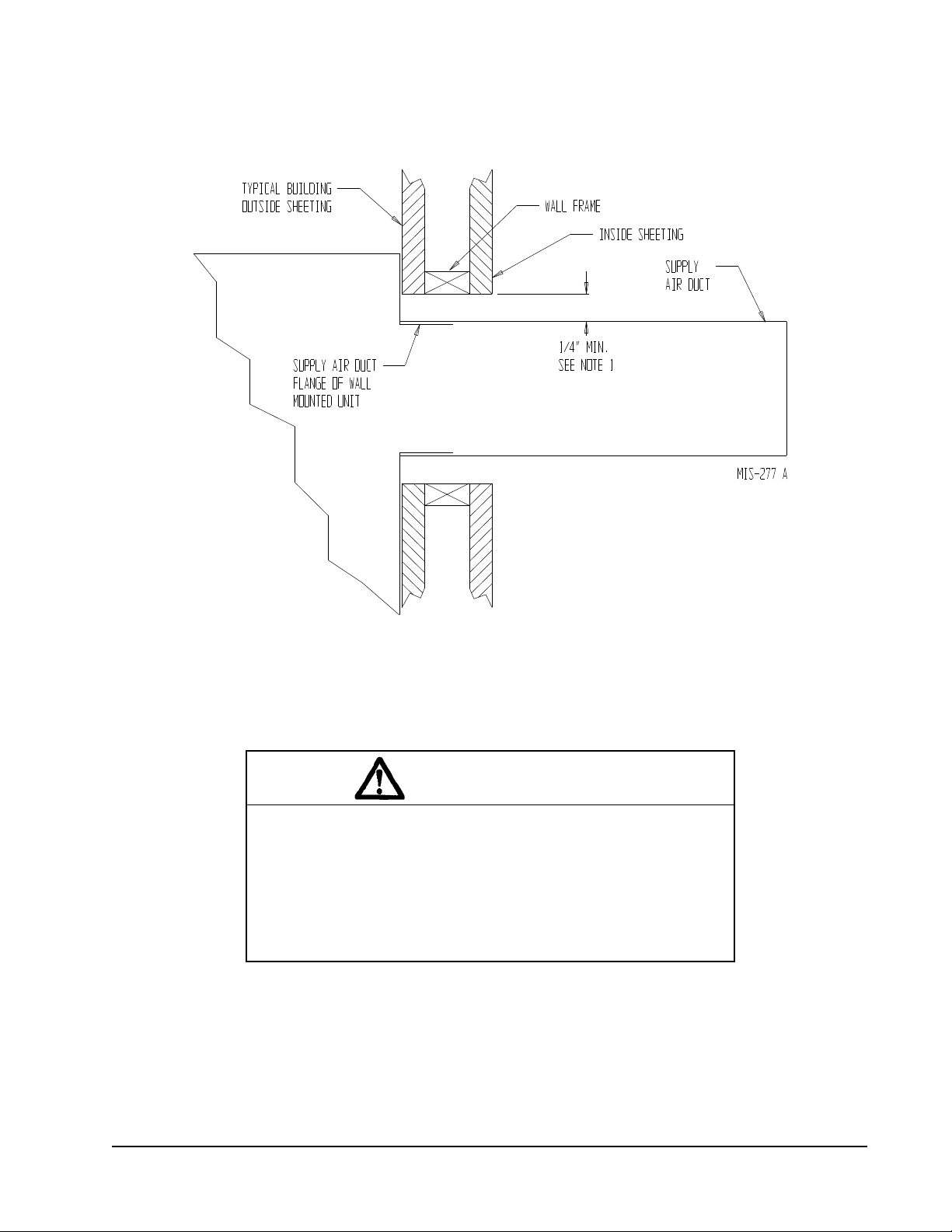
FIGURE 4
Electric Heat Clearance
W30H2, W36H2, W42H2, W48H2, W60H2
SIDE SECTION VIEW OF SUPPLY AIR DUCT FOR
WALL MOUNTED UNIT SHOWING 1/4" CLEARANCE
TO COMBUSTIBLE SURFACES.
WARNING
A minimum of 1/4" clearance must be maintained between the
supply air duct and combustible materials. This is required for the
rst 3ʹ of ducting.
It is important to insure that the 1/4" minimum spacing is
maintained at all points.
Failure to do this could result in overheating the combustible
material and may result in a re causing damage, injury or death.
Manual 2100-604B
Page 11 of 28
Page 12
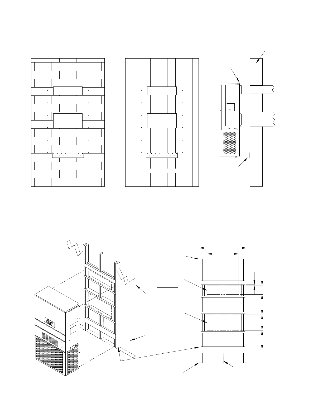
Wall Mounting Instructions
DUCT
OPENING
RETURN AIR
SUPPLY AIR
WOOD FRAME WALL INSTALLATION
OPENING
WALL BEFORE
MOUNT ON UNIT
OPENING
BEFORE INSTALLATION
BOTTOM MOUNTING
CONCRETE BLOCK WALL INSTALLATION
BRACKET. MOUNT ON
OPENING
WOOD OR STEEL SIDING
OPENING
INSTALLING UNIT.
RETURN AIR
WALL STRUCTURE
RETURN AIR
SUPPLY AIR
FACTORY SUPPLIED
RAIN FLASHING.
SUPPLY AIR
MIS-548 A
SIDE VIEW
I
A
C
K
E + 1.000
B
1.000
SUPPLY DUCT
OVER FRAME
INTERIOR FINISHED WALL
ALL AROUND DUCT
FRAMING MATERIAL
EXTERIOR FINISH WALL
OPENING
FOR ACTUAL DIMENSIONS.
2 x 4'S, 2 x 6'S &/OR
STRUCTURAL STEEL
ATTACH TO TOP
1.000" CLEARANCE
1.000" CLEARANCE
PLATE OF WALL
C
SEE UNIT DIMENSIONS, FIGURE 2,
OPENING
RETURN DUCT
2 x 6
ATTACH TO BOTTOM
OVER FRAME
PLATE OF WALL
L
THIS STRUCTURAL MEMBER
LOCATED TO MATCH STUD
SPACING FOR REST OF WALL.
A SECOND MEMBER MAY BE
REQUIRED FOR SOME WALLS.
MIS-549 B
ALL AROUND DUCT
SEE FIGURE 3 – MOUNTING INSTRUCTIONS
FIGURE 5
FIGURE 6
Wall Mounting Instructions
IF REQUIRED
IF REQUIRED
Manual 2100-604B
Page 12 of 28
Page 13
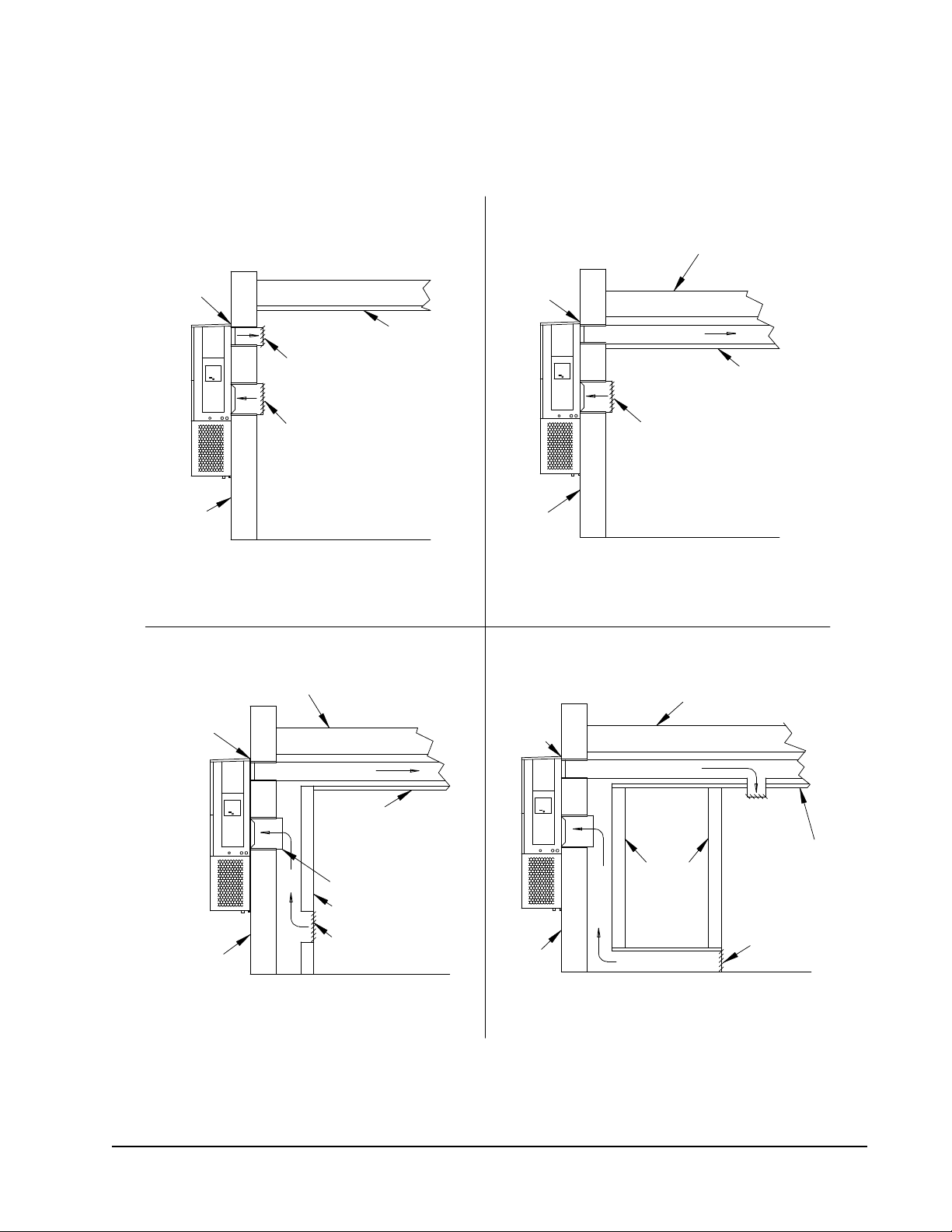
FIGURE 7
LOWERED
RAISED FLOOR
RAFTERS
SUPPLY AIR
CEILING SURFACE
WALL SLEEVE
RETURN AIR
CLOSET WALL
GRILLE
FLASHING
RETURN AIR
FLASHING
SUPPLY DUCT MAYBE LOCATED IN AN ATTIC
OR BELOW CEILING RAFTERS AS SHOWN
SUPPLY DUCT MAY BE LOCATED IN AN ATTIC
SURFACE
RAFTERS
FINISHED CEILING
SUPPLY AIR DUCT
WALL
OPENING W/ GRILLE
SUPPLY DUCT MAYBE LOCATED IN AN ATTIC
OR BELOW CEILING RAFTERS AS SHOWN
CEILING
RAIN
RETURN AIR
SLEEVE
WALL
SUPPLY AIR DUCT
RAFTERS
RAFTERS
RETURN AIR
OPENING W/ GRILLE
RAIN
FALSE WALL INSTALLATION
DUCTED SUPPLY
GRILLE
OUTSIDE
SPACE
FALSE WALL
RETURN AIR GRILLE
OUTSIDE
OR BELOW CEILING RAFTERS AS SHOWN
FINISHED CEILING SURFACE
RAIN
FLASHING
RAIN
FLASHING
RETURN AT UNITNO DUCT
WALL
SUPPLY AIR DUCT
CLOSET INSTALLATION
RETURN AIR
FINISHED
FINISHED CEILING SURFACE
MIS-550 B
FREE AIR FLOW
OUTSIDE
WALL
OUTSIDE
WALL
SUPPLY AIR DUCT
W/ GRILLE
Common Wall Mounting Installations
Manual 2100-604B
Page 13 of 28
Page 14

WIRING – MAIN POWER
WIRING – LOW VOLTAGE WIRING
Refer to the unit rating plate for wire sizing information
and maximum fuse or circuit breaker size. Each
outdoor unit is marked with a “Minimum Circuit
Ampacity”. This means that the field wiring used must
be sized to carry that amount of current. Depending
on the installed KW of electric heat, there may be
two field power circuits required. If this is the case,
the unit serial plate will so indicate. All models are
suitable only for connection with copper wire. Each
unit and/or wiring diagram will be marked “Use Copper
Conductors Only”. These instructions must be adhered
to. Refer to the National Electrical Code (NEC) for
complete current carrying capacity data on the various
insulation grades of wiring material. All wiring must
conform to NEC and all local codes.
The electrical data lists fuse and wire sizes (75° C
copper) for all models including the most commonly
used heater sizes. Also shown are the number of field
power circuits required for the various models with
heaters.
The unit rating plate lists a maximum time delay relay
fuse or circuit breaker that is to be used with the
equipment. The correct size must be used for proper
circuit protection and also to assure that there will
be no nuisance tripping due to the momentary high
starting current of the compressor motor.
All 230/208V 1 phase and 3 phase equipment have
dual primary voltage transformers.
All equipment
leaves the factory wired on 240V tap. For 208V
operation, reconnect from 240V to 208V tap. The
acceptable operating voltage range for the 240 and
208V taps are:
TAP RANGE
240 253 – 216
208 220 – 187
NOTE: The voltage should be measured at the field
power connection point in the unit and while
the unit is operating at full load (maximum
amperage operating condition).
For wiring size and connections, refer to Wiring
Manual 2100-516.
The disconnect access door on this unit may be locked
to prevent unauthorized access to the disconnect. To
convert for the locking capability, bend the tab located
in the bottom left-hand corner of the disconnect
opening under the disconnect access panel straight
out. This tab will now line up with the slot in the door.
When shut, a padlock may be placed through the hole
in the tab preventing entry.
See “Start Up” section for important information on
three phase scroll compressor start ups.
See Table 4 for Electrical Specifications.
Manual 2100-604B
Page 14 of 28
Page 15
START UP
THESE UNITS REQUIRE R-410A
REFRIGERANT AND POLYOL ESTER OIL.
GENERAL
1. Use separate service equipment to avoid cross
contamination of oil and refrigerants.
2. Use recovery equipment rated for R-410A
refrigerant.
3. Use manifold gauges rated for R-410A (800
psi/250 psi low).
4. R-410A is a binary blend of HFC-32 and HFC-125.
5. R-410A is nearly azeotropic—similar to R-22 and
R-12. Although nearly azeotropic, charge with
liquid refrigerant.
6. R-410A operates at 40-70% higher pressure
than R-22 and systems designed for R-22 cannot
withstand this higher pressure.
7. R-410A has an ozone depletion potential of zero,
but must be reclaimed due to its global warming
potential.
8. R-410A compressors use Polyol Ester oil.
9. Polyol Ester oil is hygroscopic; it will rapidly absorb
moisture and strongly hold this moisture in the oil.
10. A liquid line dryer must be used—even a deep
vacuum will not separate moisture from the oil.
11. Limit atmospheric exposure to 15 minutes.
12. If compressor removal is necessary, always plug
compressor immediately after removal. Purge with
small amount of nitrogen when inserting plugs.
TOPPING OFF SYSTEM CHARGE
If a leak has occurred in the system, Bard
Manufacturing recommends reclaiming, evacuating
(see criteria above) and charging to the nameplate
charge. If done correctly, topping off the system charge
can be done without problems.
With R-410A, there are no significant changes in the
refrigerant composition during multiple leaks and
recharges. R-410A refrigerant is close to being an
azeotropic blend (it behaves like a pure compound
or single component refrigerant). The remaining
refrigerant charge, in the system, may be used after
leaks have occurred and then “top-off” the charge by
utilizing the pressure charts on the inner control panel
cover as a guideline.
REMEMBER: When adding R-410A refrigerant, it
must come out of the charging cylinder/tank as a liquid
to avoid any fractionation, and to insure optimal system
performance. Refer to instructions for the cylinder that
is being utilized for proper method of liquid extraction.
WARNING
Failure to conform to these practices
could lead to damage, injury or death.
SAFETY PRACTICES
1. Never mix R-410A with other refrigerants.
2. Use gloves and safety glasses. Polyol Ester oils
can be irritating to the skin, and liquid refrigerant
will freeze the skin.
3. Never use air and R-410A to leak check; the
mixture may become flammable.
4. Do not inhale R-410A—the vapor attacks
the nervous system, creating dizziness, loss
of coordination and slurred speech. Cardiac
irregularities, unconsciousness and ultimate death
can result from breathing this concentration.
5. Do not burn R-410A. This decomposition
produces hazardous vapors. Evacuate the area if
exposed.
6. Use only cylinders rated DOT4BA/4BW 400.
7. Never fill cylinders over 80% of total capacity.
8. Store cylinders in a cool area, out of direct
sunlight.
9. Never heat cylinders above 125°F.
10. Never trap liquid R-410A in manifold sets, gauge
lines or cylinders. R-410A expands significantly
at warmer temperatures. Once a cylinder or line is
full of liquid, any further rise in temperature will
cause it to burst.
Manual 2100-604B
Page 15 of 28
Page 16

IMPORTANT INSTALLER NOTE
PHASE MONITOR
For improved start up performance, wash the indoor
coil with a dishwashing detergent.
HIGH AND LOW PRESSURE SWITCH
All W**H wall mounted air conditioner series models
are supplied with a remote reset for the high and low
pressure switch. If tripped, this pressure switch may
be reset by turning the thermostat off then back on
again.
THREE PHASE SCROLL COMPRESSOR
START UP INFORMATION
Scroll compressors, like several other types of
compressors, will only compress in one rotational
direction. Direction of rotation is not an issue with
single phase compressors since they will always start
and run in the proper direction.
However, three phase compressors will rotate in either
direction depending upon phasing of the power.
Since there is a 50-50 chance of connecting power
in such a way as to cause rotation in the reverse
direction, verification of proper rotation must be made.
Verification of proper rotation direction is made by
observing that suction pressure drops and discharge
pressure rises when the compressor is energized.
Reverse rotation also results in an elevated sound level
over that with correct rotation, as well as substantially
reduced current draw compared to tabulated values.
Verification of proper rotation must be made at the
time the equipment is put into service. If improper
rotation is corrected at this time, there will be no
negative impact on the durability of the compressor.
However, reverse operation for over 1 hour may have a
negative impact on the bearing due to oil pump out.
NOTE: If compressor is allowed to run in reverse
rotation for several minutes, the compressor’s
internal protector will trip.
All three phase ZP compressors are wired identically
internally. As a result, once the correct phasing
is determined for a specific system or installation,
connecting properly phased power leads to the same
Fusite terminal should maintain proper rotation
direction.
The direction of rotation of the compressor may be
changed by reversing any two line connections to the
unit.
All units with three phase scroll compressors are
equipped with a three phase line monitor to prevent
compressor damage due to phase reversal.
The phase monitor in this unit is equipped with two
LEDs. If the Y signal is present at the phase monitor
and phases are correct the green LED will light.
If phases are reversed, the red fault LED will be lit and
compressor operation is inhibited.
If a fault condition occurs, reverse two of the supply
leads to the unit. Do not reverse any of the unit factory
wires as damage may occur.
CONDENSER FAN OPERATION
Applies to W42, W48 and W60 models only. The
condenser fan motor on 230/208 volt, one and three
phase, 60 HZ units is a two-speed motor that comes
factory wired on high speed for peak performance. If
ambient conditions permit, it can be reconnected to
low speed (red wire) for lower sound level. See wiring
diagram.
50 HZ models must have fan wired on low speed.
These models are factory wired on low speed.
SERVICE HINTS
1. Caution owner/operator to maintain clean air filters
at all times and to not needlessly close off supply
and return air registers. This reduces airflow
through the system, which shortens equipment
service life as well as increasing operating costs.
2. Check all power fuses or circuit breakers to be sure
they are the correct rating.
3. Periodic cleaning of the outdoor coil to permit full
and unrestricted airflow circulation is essential.
SEQUENCE OF OPERATION
COOLING – Circuit R-Y makes at thermostat pulling
in compressor contactor, starting the compressor
and outdoor motor. The G (indoor motor) circuit is
automatically completed on any call for cooling operation
or can be energized by manual fan switch on subbase for
constant air circulation.
HEATING – A 24V solenoid coil on reversing valve
controls heating cycle operation. Two thermostat
options, one allowing “Auto” changeover from cycle to
cycle and the other constantly energizing solenoid coil
during heating season, and thus eliminating pressure
equalization noise except during defrost, are to be used.
On “Auto” option a circuit is completed from R-W1 and
R-Y on each heating “on” cycle, energizing reversing
valve solenoid and pulling in compressor contactor
starting compressor and outdoor motor. R-G also make
Manual 2100-604B
Page 16 of 28
Page 17

starting indoor blower motor. Heat pump heating cycle
now in operation. The second option has no “Auto”
changeover position, but instead energizes the reversing
valve solenoid constantly whenever the system switch on
subbase is placed in “Heat” position, the “B” terminal
being constantly energized from R. A Thermostat demand
for heat completes R-Y circuit, pulling in compressor
contactor starting compressor and outdoor motor. R-G
also make starting indoor blower motor.
PRESSURE SERVICE PORTS
High and low pressure service ports are installed on
all units so that the system operating pressures can be
observed. Pressure tables covering all models can be
found on page 22. It is imperative to match the correct
pressure table to the unit by model number.
This unit employs high-flow Coremax valves instead of
the typical Shrader type valves.
WARNING! Do NOT use a Schrader valve core removal
tool with these valves. Use of such a tool could result in
eye injuries or refrigerant burns!
To change a Coremax valve without first removing the
refrigerant, a special tool is required which can be
obtained at www.fastestinc.com/en/SCCA07H. See the
replacement parts manual for replacement core part
numbers.
DEFROST CYCLE
The defrost cycle is controlled by temperature and time
on the solid state heat pump control.
When the outdoor temperature is in the lower
40°F temperature range or colder, the outdoor coil
temperature is 32°F or below. This coil temperature
is sensed by the coil temperature sensor mounted near
the bottom of the outdoor coil. Once coil temperature
reaches 30°F or below, the coil temperature sensor
sends a signal to the control logic of the heat pump
control and the defrost timer will start accumulating
run time.
After 30, 60 or 90 minutes of heat pump operation at
30°F or below, the heat pump control will place the
system in the defrost mode.
During the defrost mode, the refrigerant cycle switches
back to the cooling cycle, the outdoor motor stops,
electric heaters are energized, and hot gas passing
through the outdoor coil melts any accumulated frost.
When the temperature rises to approximately 57°F, the
coil temperature sensor will send a signal to the heat
pump control which will return the system to heating
operations automatically.
If some abnormal or temporary condition such as a high
wind causes the heat pump to have a prolonged defrost
cycle, the heat pump control will restore the system to
heating operation automatically after 8 minutes.
The heat pump defrost control board has an option of
30, 60 or 90-minute setting. By default, this unit is
shipped from the factory with the defrost time on the
60 minute pin. If circumstances require a change
to another time, remove the wire from the 60-minute
terminal and reconnect to the desired terminal. Refer
to Figure 8.
There is a cycle speed up jumper on the control. This
can be used for testing purposes to reduce the time
between defrost cycle operation without waiting for
time to elapse.
Use a small screwdriver or other metallic object,
or another ¼" QC, to short between the SPEEDUP
terminals to accelerate the HPC timer and initiate
defrost.
Be careful not to touch any other terminals with the
instrument used to short the SPEEDUP terminals.
It may take up to 10 seconds with the SPEEDUP
terminals shorted for the speedup to be completed and
the defrost cycle to start.
As soon as the defrost cycle kicks in remove the
shorting instrument from the SPEEDUP terminals.
Otherwise the timing will remain accelerated and
run through the 1-minute minimum defrost length
sequence in a matter of seconds and will automatically
terminate the defrost sequence.
There is an initiate defrost jumper (sen jump) on the
control that can be used at any outdoor ambient during
the heating cycle to simulate a 0° coil temperature.
This can be used to check defrost operation of the unit
without waiting for the outdoor ambient to fall into the
defrost region.
By placing a jumper across the SEN JMP terminals (a
¼" QC terminal works best) the defrost sensor mounted
on the outdoor coil is shunted out and will activate
the timing circuit. This permits the defrost cycle to
be checked out in warmer weather conditions without
the outdoor temperature having to fall into the defrost
region.
In order to terminate the defrost test the SEN JMP
jumper must be removed. If left in place too long, the
compressor could stop due to the high pressure control
opening because of high pressure condition created
by operating in the cooling mode with outdoor fan off.
Pressure will rise fairly fast as there is likely no actual
frost on the outdoor coil in this artificial test condition.
There is also a 5-minute compressor time delay
function built into the HPC. This is to protect the
compressor from short cycling conditions. The board’s
LED will have a fast blink rate when in the compressor
time delay. In some instances, it is helpful to the
service technician to override or speed up this timing
period, and shorting out the SPEEDUP terminals for a
few seconds can do this.
Manual 2100-604B
Page 17 of 28
Page 18
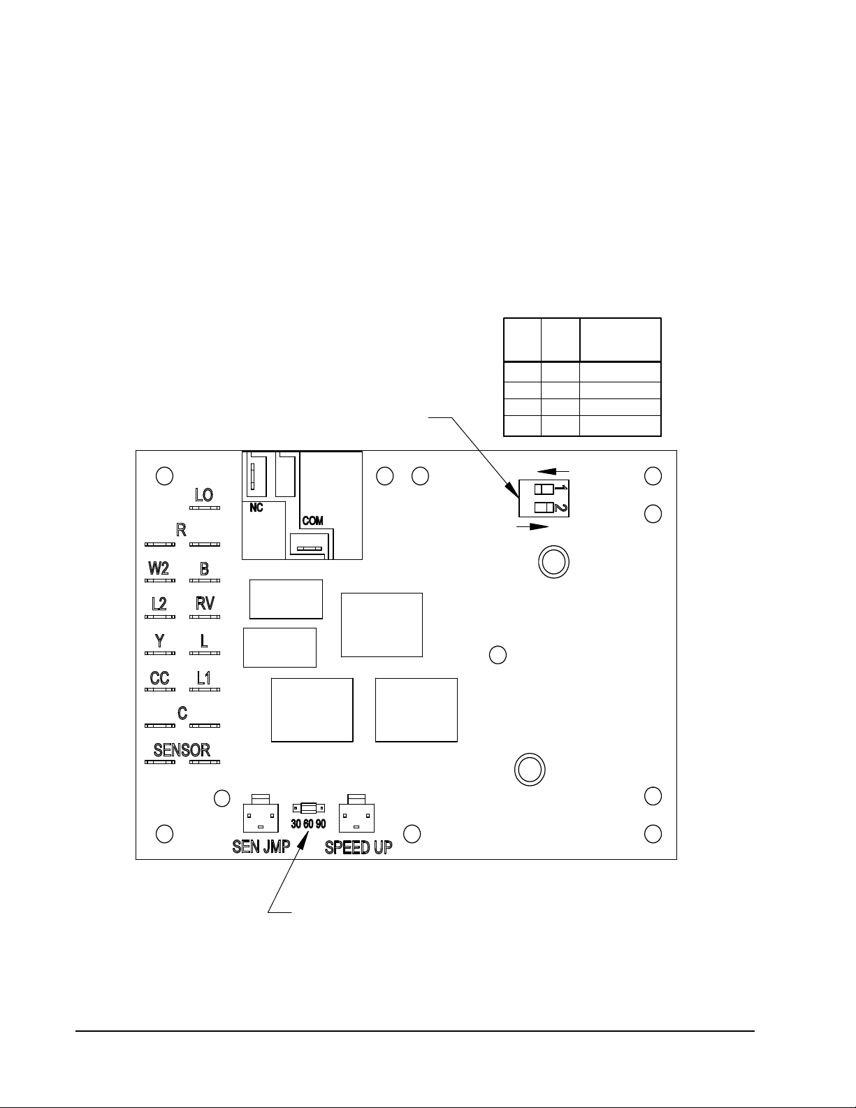
Low Pressure Switch Bypass Operation - The control
120*
SW1SW
2 TIME (SEC)
OFF
OFF
ON
ON
OFF
ON
OFF
ON
30
60
180
OFF
LOW PRESSURE BYPASS TIMER SWITCH
*(FACTORY SETTING 120 SECONDS)
ACCUMULATED DEFROST TIME TIMER
(FACTORY SETTING 60 MIN.)
ON
has a selectable (SW1) low pressure switch bypass set
up to ignore the low pressure switch input during the
first (30, 60, 120 or 180 seconds) of “Y” operation.
After this period expires, the control will then monitor
the low pressure switch input normally to make sure
that the switch is closed during “Y” operation.
Defrost Control Board
High Pressure Switch Operation - The control has a
built-in lockout system that allows the unit to have the
high pressure switch trip up to two times in 1 hour and
only encounter a “soft” lockout. A “soft” lockout shuts
the compressor off and waits for the pressure switch to
reset, which at that point then allows the compressor
to be restarted as long as the 5-minute short cycle
timer has run out. If the high pressure switch trips a
third time within one hour, the unit is in “hard” lockout
indicating something is certainly wrong and it will not
restart itself.
FIGURE 8
Manual 2100-604B
Page 18 of 28
MIS-2668A
Page 19
SERVICE
SOLID STATE HEAT PUMP CONTROL
TROUBLESHOOTING PROCEDURE
1. NOTE: A thorough understanding of the defrost
cycle sequence is essential. Review that section
earlier in this manual prior to troubleshooting the
control. Turn on AC power supply to unit.
2. Turn thermostat blower switch to “fan on”—
the indoor blower should start. (If it doesn’t,
troubleshoot indoor unit and correct problem.)
3. Turn thermostat blower to “auto” position. Indoor
blower should stop. NOTE: Many models have a
1-minute blower time delay on “off” command;
wait for this to time-out.
4. Set system switch to “heat” or “cool”. Adjust
thermostat to call for heat or cool. The indoor
blower, compressor and outdoor fan should start.
NOTE: If there was no power to 24 volt transformer,
the compressor and outdoor fan motor will not start for
5 minutes. This is because of the compressor short
cycle protection.
LED BLINK CODES
BLINK FUNCTION
Slow Normal function (1.0 sec on/1.0 sec off)
Fast Compressor Delay timer active (0.1 sec on/0.1 sec
off)
1 Low pressure switch failure
2 High pressure switch failure/“Soft” Lockout
3 Defrost mode active
4 High pressure switch failure/“Hard” Lockout
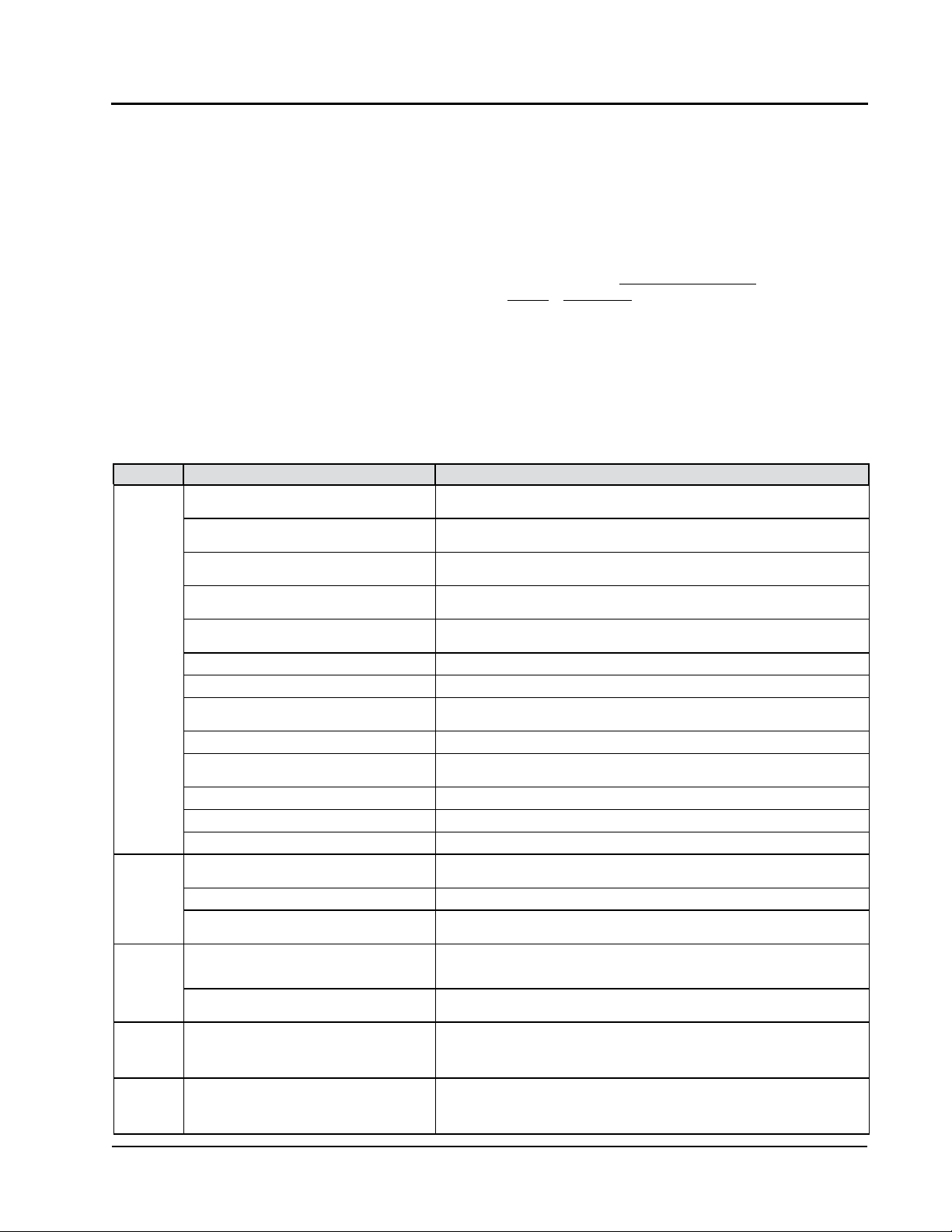
TABLE 1 – TROUBLESHOOTING
Sympton Description, Check & Possible Causes What & How to Check / Repair
Compressor
will not start
(heating or
cooling)
Fan outdoor
motor does
not run
(cooling or
heating except
during defrost)
Reversing
valve does not
energize
(heating only)
Unit will not go
into defrost
(heating only)
Unit will not
come out of
defrost
(heating only)
1. Check for LED illumination.
Is there an LED illuminated on the board (ashing)?
2. Check for error codes.
Is the LED ashing a Code?
3. Check for power at board.
Is there 24 volts AC between R and C?
4. Check codes.
What code is blinking?
5. Compressor delay active.
Wait for 5 minute delay or jump board's "speed up pins".
6. Low pressure fault. Check wiring circuit and unit pressures.
7. High pressure fault. Check wiring circuit and unit pressures.
8. Check for Compressor input signal.
Is there 24 volts AC between Y and C?
9. No power to board. The unit either does not have unit voltage, the transformer is bad or the unit wiring is incorrect.
10. Check for Compressor output signal.
Is there 24 volts AC between CC & C?
11. No "Y" compressor input signal.
12. No "CC" compressor output signal. Check compressor contactor for proper operation and nally check compressor.
13. Faulty board. Replace defrost board.
Heat pump control defective
Motor defective Check for open or shorted motor winding. Replace motor.
Motor capacitor defective Check capacitor rating. Check for open or shorted capacitor. Replace capacitor.
Heat pump control defective
Reversing valve solenoid coil defective
Temperature sensor or heat pump control defective
Temperature sensor or heat pump control defective
Yes = go to Step #2; No = go to Step #3
Yes = go to Step #4; No = go to Step #8
Yes = go to Step #13; No = go to Step #9
Code "1", go to Step #6; Code "2", go to Step#7; Fast Blink, go to Step #5
Check for proper operation; if still needed, go back to Step #1.
Yes = go to Step #10; No = go to Step #11
Yes = go to Step #12; No = go to Step #13
Check thermostat wiring, incorrect phase of unit (see section on Phase Monitor), and nally unit wiring.
Check across fan relay on heat pump control. (Com-NC)
Replace heat pump control.
Check for 24V between RV-C and B-C.
1. Check control circuit wiring.
2. Replace heat pump control.
Check for open or shorted coil.
Replace solenoid coil.
Disconnect temperature sensor from board and jumper across "SPEEDUP" terminals and "SEN
JMP" terminals. This should cause the unit to go through a defrost cycle within one minute.
1. If unit goes through defrost cycle, replace temperature sensor.
2. If unit does not go through defrost cycle, replace heat pump control.
Jumper across "SPEEDUP" terminal.
This should cause the unit to come out of defrost within one minute.
1. If unit comes out of defrost cycle, replace temperature sensor.
2. If unit does not come out of defrost cycle, replace heat pump control.
Manual 2100-604B
Page 19 of 28
Page 20
CHECKING TEMPERATURE SENSOR
OUTSIDE UNIT CIRCUIT
1. Disconnect temperature sensor from board and
from outdoor coil.
2. Use an ohmmeter and measure the resistance of
the sensor. Also use ohmmeter to check for short
or open.
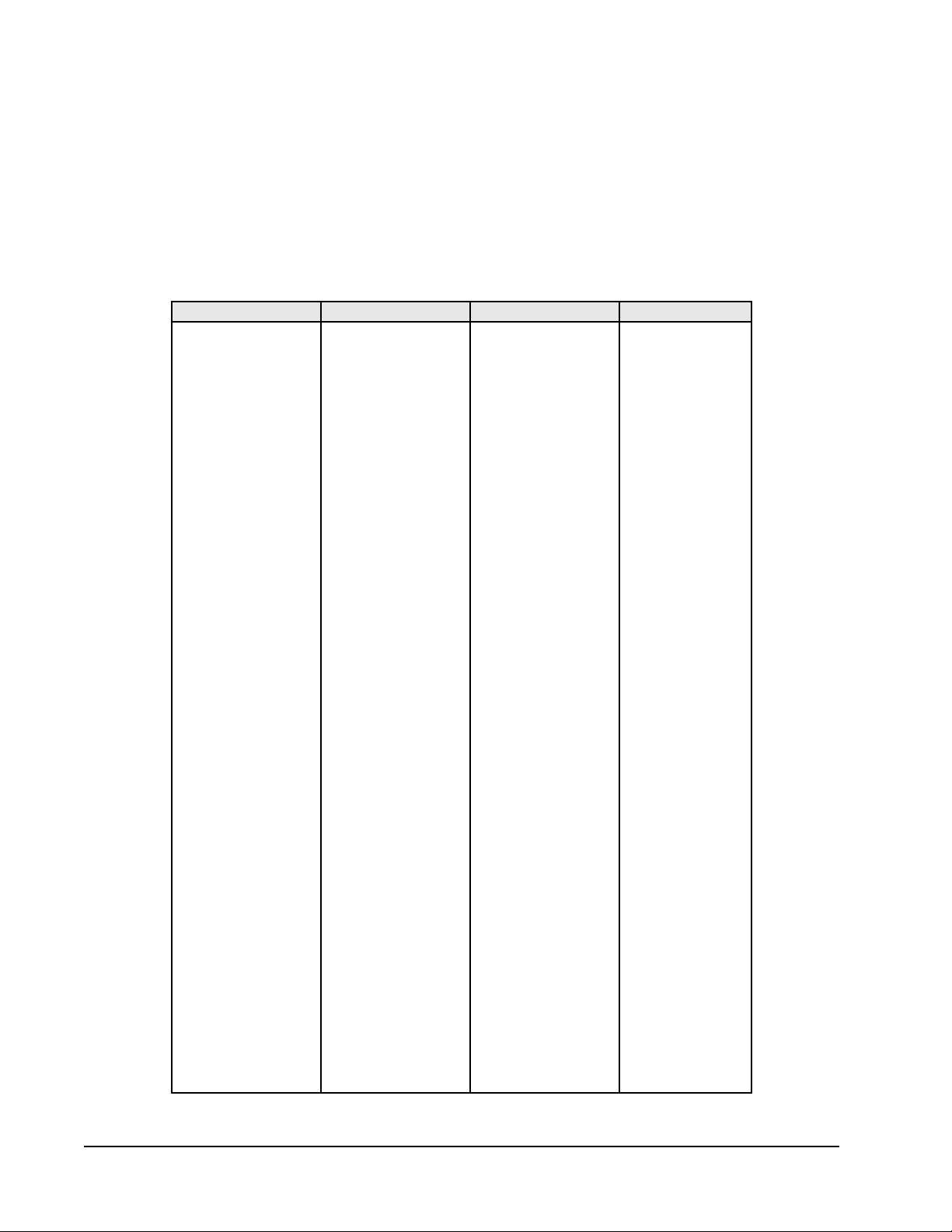
Temperature (F) vs. Resistance (R) of Temperature Sensor
F R F R F R F R
-25.0 196871 13.0 56985 53.0 19374 89.0 7507
-24.0 190099 14.0 55284 52.0 18867 90.0 7334
-23.0 183585 15.0 53640 53.0 18375 91.0 7165
-22.0 177318 16.0 52051 54.0 17989 92.0 7000
-21.0 171289 17.0 50514 55.0 17434 93.0 6840
-20.0 165487 18.0 49028 56.0 16984 94.0 6683
-19.0 159904 19.0 47590 57.0 16547 95.0 6531
-18.0 154529 20.0 46200 58.0 16122 96.0 6383
-17.0 149355 21.0 44855 59.0 15710 97.0 6239
-16.0 144374 22.0 43554 60.0 15310 98.0 6098
-15.0 139576 23.0 42295 61.0 14921 99.0 5961
-14.0 134956 24.0 41077 62.0 14544 100.0 5827
-13.0 130506 25.0 39898 63.0 14177 101.0 5697
-12.0 126219 26.0 38757 64.0 13820 102.0 5570
-11.0 122089 27.0 37652 65.0 13474 103.0 5446
-10.0 118108 28.0 36583 66.0 13137 104.0 5326
-9.0 114272 29.0 35548 67.0 12810 105.0 5208
-8.0 110575 30.0 34545 68.0 12492 106.0 5094
-7.0 107010 31.0 33574 69.0 12183 107.0 4982
-6.0 103574 32.0 32634 70.0 11883 108.0 4873
-5.0 100260 33.0 31723 71.0 11591 109.0 4767
-4.0 97064 34.0 30840 72.0 11307 110.0 4663
-3.0 93981 35.0 29986 73.0 11031 111.0 4562
-2.0 91008 36.0 29157 74.0 10762 112.0 4464
-1.0 88139 37.0 28355 75.0 10501 113.0 4367
0.0 85371 38.0 27577 76.0 10247 114.0 4274
1.0 82699 39.0 26823 77.0 10000 115.0 4182
2.0 80121 40.0 26092 78.0 9760 116.0 4093
3.0 77632 41.0 25383 79.0 9526 117.0 4006
4.0 75230 42.0 24696 80.0 9299 118.0 3921
5.0 72910 43.0 24030 81.0 9077 119.0 3838
6.0 70670 44.0 23384 82.0 8862 120.0 3757
7.0 68507 45.0 22758 83.0 8653 121.0 3678
8.0 66418 46.0 22150 84.0 8449 122.0 3601
9.0 64399 47.0 21561 85.0 8250 123.0 3526
10.0 62449 48.0 20989 86.0 8057 124.0 3452
11.0 60565 49.0 20435 87.0 7869
12.0 58745 50.0 19896 88.0 7686
3. Check resistance reading to chart of resistance.
Use sensor ambient temperature. (Tolerance of
part is ± 10%.)
4. If sensor resistance reads very low, then sensor is
shorted and will not allow proper operation of the
heat pump control.
5. If sensor is out of tolerance, shorted, open or reads
very low ohms then it should be replaced.
Manual 2100-604B
Page 20 of 28
Page 21
FAN BLADE SETTING DIMENSIONS
REMOVAL OF FAN SHROUD
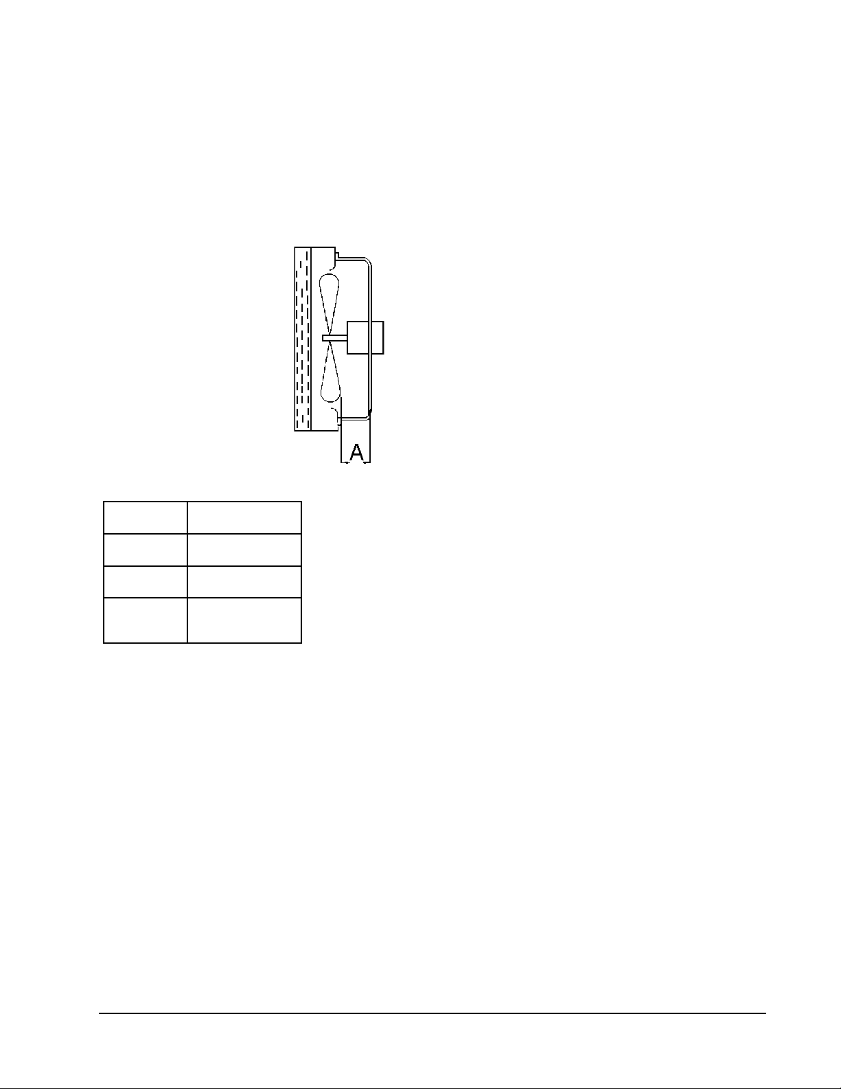
The correct fan blade setting for proper air delivery
across the outdoor coil is shown in Figure 9. Refer to
Table 2 for unit specific dimension.
Any service work requiring removal or adjustment in the
fan and/or motor area will require that the dimensions
below be checked and blade adjusted in or out on the
motor shaft accordingly.
FIGURE 9
Fan Blade Setting
TABLE 2
MIS-1724
Fan Blade Dimension
MODEL
W18H2
W24H2
W30H2
W36H2
W42H2
W48H2
W60H2
DIMENSION A
(INCHES)
1.00"
1.25"
1.75"
1. Disconnect all power to the unit.
2. Remove the screws holding both grilles, one on
each side of unit, and remove grilles.
3. Remove nine screws holding fan shroud to
condenser and bottom.
4. Unwire condenser fan motor.
5. Slide complete motor, fan blade and shroud
assembly out the left side of the unit.
6. Service motor/fan as needed.
7. Reverse steps to re-install.
R-410A REFRIGERANT CHARGE
This unit was charged at the factory with the quantity of
refrigerant listed on the serial plate. AHRI capacity and
efficiency ratings were determined by testing with this
refrigerant charge quantity.
The following pressure tables show nominal pressures
for the units. Since many installation specific
situations can affect the pressure readings, this
information should only be used by certified technicians
as a guide for evaluating proper system performance.
They shall not be used to adjust charge. If charge is in
doubt, reclaim, evacuate and recharge the unit to the
serial plate charge.
Manual 2100-604B
Page 21 of 28
Page 22
TABLE 3A – Cooling Pressure Table
RETURN
MODEL
W18H2
W24H2
W30H2
W36H2
W42H2
W48H2
W60H2
Low side pressure ± 4 PSIG
High side pressure ± 10 PSIG
Tables are based upon rated CFM (airflow) across the evaporator coil. If there is any doubt as to correct operating charge being in the system, the charge should
be removed, system evacuated and recharged to serial plate charge weight.
NOTE: Pressure table based on high speed condenser fan operation. If condensing pressures appear elevated check condenser fan wiring. See
“Condenser Fan Operation”.
AIR
TEMP.
75 DB
62 WB
80 DB
67 WB
85 DB
72 WB
75 DB
62 WB
80 DB
67 WB
85 DB
72 WB
75 DB
62 WB
80 DB
67 WB
85 DB
72 WB
75 DB
62 WB
80 DB
67 WB
85 DB
72 WB
75 DB
62 WB
80 DB
67 WB
85 DB
72 WB
75 DB
62 WB
80 DB
67 WB
85 DB
72 WB
75 DB
62 WB
80 DB
67 WB
85 DB
72 WB
PRESSURE
Low Side
High Side
Low Side
High Side
Low Side
High Side
Low Side
High Side
Low Side
High Side
Low Side
High Side
Low Side
High Side
Low Side
High Side
Low Side
High Side
Low Side
High Side
Low Side
High Side
Low Side
High Side
Low Side
High Side
Low Side
High Side
Low Side
High Side
Low Side
High Side
Low Side
High Side
Low Side
High Side
Low Side
High Side
Low Side
High Side
Low Side
High Side
75° 80° 85° 90° 95° 100° 105° 110° 115° 120°
132
292
141
299
146
309
124
329
133
337
138
349
125
326
134
334
139
346
122
329
131
337
136
349
127
354
136
363
141
376
129
352
138
361
143
374
126
332
135
341
140
353
134
311
143
319
148
330
126
351
135
360
140
373
128
350
137
359
142
372
124
351
133
360
138
373
130
372
139
382
144
395
132
374
141
384
146
397
128
352
137
361
142
374
AIR TEMPERATURE ENTERING OUTDOOR COIL
137
332
146
340
151
352
128
373
137
383
142
396
131
373
140
383
145
396
126
375
135
385
140
398
132
392
141
402
146
416
134
398
143
408
148
422
131
373
140
383
145
396
138
353
148
362
153
375
131
398
140
408
145
422
133
398
142
408
147
422
128
399
137
409
142
423
134
413
143
424
148
439
136
422
145
433
150
448
133
397
142
407
147
421
140
376
150
386
155
400
133
423
142
434
147
449
136
423
144
438
150
449
130
424
137
444
144
450
135
437
143
452
149
464
137
449
147
460
152
476
135
421
143
434
149
447
142
400
152
410
157
424
135
449
144
460
149
476
137
448
147
459
152
475
132
449
141
461
146
477
136
461
145
473
150
490
139
476
149
488
154
505
137
448
147
459
152
475
144
424
154
435
159
450
137
475
146
487
151
504
139
472
149
484
154
501
135
476
144
488
149
505
137
488
146
500
151
518
141
505
151
518
156
536
139
476
149
488
154
505
146
450
156
462
161
478
138
503
148
516
153
534
141
496
151
509
156
527
137
503
146
516
151
534
137
516
146
529
151
548
143
535
153
549
158
568
141
505
151
518
156
536
148
477
158
489
164
506
140
531
150
545
155
564
143
522
153
535
158
554
138
530
148
544
153
563
137
546
146
560
151
580
145
566
155
581
160
601
143
536
153
550
158
569
150
505
160
518
166
536
142
561
152
575
157
595
145
547
155
561
160
581
141
559
151
573
156
593
136
578
145
593
150
614
146
600
156
615
161
637
145
568
155
583
160
603
RETURN
MODEL
AIR
TEMP.
W18H2 70
W24H2 70
W30H2 70
W36H2 70
W42H2 70
W48H2 70
W60H2 70
Manual 2100-604B
Page 22 of 28
TABLE 3B – Heating Pressures (All Temperatures °F)
AIR TEMPERATURE ENTERING OUTDOOR COIL
PRESSURE
Low Side
High Side482905228556282612826628572290792978730795319
Low Side
High Side57292552965530157307593146432370332773428635496367
Low Side
High Side53254532665527858290613016631272322803328834297351
Low Side
High Side47281492825128355287592926430070308773198533193345
Low Side
High Side50299503005230354308583146232268331753428435593370
Low Side
High Side42268452704927454278592846429170298773078431792327
Low Side
High Side39294432964730052305583116331970328763388434992362
0 5 10 15 20 25 30 35 40 45 50 55 60
104
334
114
352
108
380
108
360
103
361
104
386
100
339
100
376
124
372
121
395
119
369
113
379
115
404
109
352
109
391
135
394
135
411
132
377
124
398
128
423
118
366
118
408
Page 23
TABLE 4A
Electrical Specifications
No.
Field
Power
Circuits
1
1 or 2
1
1
1
1
1 or 2
1
1
1
1
1
1
1
1 or 2
1 or 2
1
1
1
1
1
1
1
1
1
1
1 or 2
1 or 2
1 or 2
1
1
1
1
1
1
1
1
1
1
1 or 2
1 or 2
1 or 2
1 or 2
1
1
1
1
1 or 2
1
1
1
1
1 or 2
1 or 2
1 or 2
1 or 2
1
1
1
1 or 2
1
1
1
A04
A08
A04
A08
B06
C06
A05*
A10*
B06
B09*
C06
C09*
C15
A05
A10*
A15
B06
B09*
B15
C06
C09*
C15
A04
A05
A10
m A15
B06
B09
B15
C06
C09
C15
A04
A05
A10
m A15
m A20
B06
B09
B15
B18
C09
C15
A05
A10
m A15
m A20
B09
B15
B18
C09
C15
Rated Volts
& Phase
230/208-111
230/208-111
230/208-3
460-3
230/208-111
230/208-311
460-3
230/208-1
230/208-3
460-3
230/208-1
230/208-3
460-3
230/208-1
230/208-3
460-3
230/208-1
230/208-3
460-3
MODEL
W18H2-A00, A0Z
W24H2-A00, A0Z
W24H2-B00, B0Z
W24H2-C00, C0Z
W30H2-A00, A0Z*
W30H2-B00, B0Z*
W30H2-C00, C0Z*
W36H2-A00, A0Z*
W36H2-B00, B0Z*
W36H2-C00, C0Z*
W42H2-A00, A0Z
W42H2-B00, B0Z
W42H2-C00, C0Z
W48H2-A00, A0Z
W48H2-B00, B0Z
W48H2-C00, C0Z
W60H2-A00, A0Z
W60H2-B00, B0Z
W60H2-C00, C0Z
These “Minimum Circuit Ampacity” values are to be used for sizing the field power conductors. Refer to the National Electrical code (latest version), Article 310 for power conductor sizing.
CAUTION: When more than one field power circuit is run through one conduit, the conductors must be derated. Pay special attention to note 8 of Table 310 regarding
Ampacity Adjustment Factors when more than three (3) current carrying conductors are in a raceway.
Maximum size of the time delay fuse or circuit breaker for protection of field wiring conductors.
Maximum KW that can operate with the heat pump on is 9KW. Full heat available during emergency heat mode.
m Maximum KW that can operate with the heat pump on is 10KW. Full heat available during emergency heat mode.
n Based on 75°copper wire. All wiring must conform to the National Electrical Code and all local codes.
* Available factory-built only with top outlet supply as an option.
IMPORTANT: While this electrical data is presented as a guide, it is important to electrically connect properly sized fuses and conductor wires in accordance with the
National Electrical Code and all local codes.
Minimum
Circuit
Ampacity
16
37
58
24
44
65
17
35
11
21
24
50
76
18
36
45
11
20
25
26
29
55
81
84
23
41
50
51
12
21
25
26
36
57
62
88
88
26
44
53
53
13
22
26
26
37
58
63
89
89
111
29
47
56
56
62
14
27
27
41
67
93
93
111
28
55
55
62
16
28
28
Single Circuit Dual Circuit
Maximum
External
Fuse or
Ckt. Brkr.
20
40
60
25
50
70
20
40
15
25
35
50
80
25
40
45
15
20
25
30
40
60
90
90
30
45
50
60
15
25
25
30
50
60
70
90
90
35
50
60
60
15
25
30
30
50
60
70
90
90
125
35
50
60
60
70
20
30
30
60
80
100
100
125
40
60
60
70
20
30
30
n
Field
Power
Wire
Size
12
8
6
10
8
6
12
8
14
10
8
8
4
10
8
8
14
12
10
10
8
6
4
4
10
8
8
8
14
10
10
10
8
6
6
3
3
8
8
6
6
14
10
10
10
8
6
6
3
3
2
8
8
6
6
6
12
10
10
8
4
3
3
2
8
6
6
6
12
10
10
Minimum
n
Ground
Wire
12
10
10
10
10
8 44 21 45 25 8 10 10 10
12
10
14
10
10
10
8 50 26 50 30 8 10 10 10
10
10
10
14
12
10
10
10
10
8
8
10
10
10
10
14
10
10
10
10
10
8
8
8
10
10
10
10
14
10
10
10
10
10
8
8
8
6
10
10
10
10
8 34 28 40 30 8 10 10 10
12
10
10
10
8
8
8
6
10
10
10
10 34 28 40 30 8 10 10 10
12
10
10
Circuit
Ampacity
Ckt. A Ckt. B Ckt. A Ckt. B Ckt. A Ckt. B Ckt. A Ckt. B
555526526060306066106101010
36
36
36
37
37
37
59
41
41
41
59
26
52
52
26
52
52
52
26
52
52
52
Maximum
External Fuse or
Ckt. Breaker
50
30
50
60
50
60
50
30
50
60
50
60
60
60
60
30
60
60
60
60
60
60
n
Field Power
Wire Size
8
10
8
8
8
10
8
8
6
8
10
8
8
6
Ground
Wire Size
10
6
10
6
10
10
6
10
6
10
6
10
10
6
10
6
10
6
10
Manual 2100-604B
Page 23 of 28
n
10
10
10
10
10
10
10
10
10
10
10
10
Page 24
TABLE 4B
Electrical Specifications — Dehumidification Models
MODEL
W24H2DA00, A0Z
W24H2DB00, B0Z
W24H2DC00, C0Z
W30H2DA00, A0Z
W30H2DB00, B0Z
W30H2DC00, C0Z
W36H2DA00, A0Z
W36H2DB00, B0Z
W36H2DC00, C0Z
W42H2DA00, A0Z
W42H2DB00, B0Z
W42H2DC00, C0Z
W48H2DA00, A0Z
W48H2DB00, B0Z
W48H2DC00, C0Z
W60H2DA00, A0Z
W60H2DB00, B0Z
W60H2DC00, C0Z
These “Minimum Circuit Ampacity” values are to be used for sizing the field power conductors. Refer to the National Electrical code (latest version), Article 310 for power conductor sizing.
CAUTION: When more than one field power circuit is run through one conduit, the conductors must be derated. Pay special attention to note 8 of Table 310 regarding
Ampacity Adjustment Factors when more than three (3) current carrying conductors are in a raceway.
Maximum size of the time delay fuse or circuit breaker for protection of field wiring conductors.
Based on 75°copper wire. All wiring must conform to the National Electrical Code and all local codes.
IMPORTANT: While this electrical data is presented as a guide, it is important to electrically connect properly sized fuses and conductor wires in accordance with the
National Electrical Code and all local codes.
Rated Volts
& Phase
A04
230/208-111
A08
230/208-3
B06
460-3
C06
A05
230/208-111
A10
B06
230/208-311
B09
C06
460-311
C09
A05
230/208-111
A10
B06
230/208-311
B09
C06
460-311
C09
A05
230/208-111 or 2
A10
B06
230/208-311
B09
C06
460-311
C09
A05
230/208-111 or 2
A10
B06
230/208-311
B09
460-3
C09
A05
230/208-111 or 2
A10
230/208-3
B09
460-3
C09
No.
Field
Power
Circuits
1 or 2
1
1
1
1
1 or 2
1
1
1 or 2
1
1
1 or 2
1
1
1 or 2
1
1
1
1 or 2
1
1
1
1
Minimum
Circuit
Ampacity
24
44
65
17
35
12
21
27
52
79
19
37
47
12
21
26
30
56
82
24
42
51
12
21
25
40
66
92
28
46
55
14
23
27
38
64
90
29
47
56
14
27
41
67
93
28
55
15
28
Single Circuit Dual Circuit
Maximum
External
Fuse or
Ckt. Brkr.
25
50
70
20
40
15
25
35
60
80
25
40
50
15
25
30
40
60
90
30
50
60
15
25
25
60
70
100
40
50
60
20
25
30
50
80
90
35
50
60
20
30
60
80
100
40
60
20
30
Field
Power
Wire
Size
10
8
6
12
8
14
10
8
6
4
10
8
8
14
10
10
10
6
4
10
8
6
14
10
10
8
6
3
8
8
6
12
10
10
8
6
3
8
8
6
12
10
8
4
3
8
6
12
10
Minimum
Ground
Wire
10
10
8 44 21 45 25 8 10 10 10
12
10
14
10
10
10
8 52 26 60 30 6 10 10 10
10
10
10
14
10
10
10
10
8 55 26 60 30 6 10 10 10
10
10
10
14
10
10
10
8
8
10
10
10
12
10
10
10
8
8
10
10
10
12
10
10
8
8
10
10
12
10
Circuit
Ampacity
Ckt. A Ckt. B Ckt. A Ckt. B Ckt. A Ckt. B Ckt. A Ckt. B
40402652505030
38382652505030
41412652606060
Maximum
External Fuse or
Ckt. Breaker
60
60
60
Field Power
Wire Size
88106101010
88106101010
106101010
8
8
Ground
Wire Size
10
10
10
Manual 2100-604B
Page 24 of 28
Page 25
TABLE 5
Recommended Airflow
Model Rated CFM * Rated ESP *
W18H
W24H 800 .20 700 - 950 High
W30H 1000 .40 930 - 1300 High
W36H 1100 .30 930 - 1350 High
W42H 1400 .30 1600 - 1150 High
W48H 1550 .20 1750 - 1285 High
W60H 1650 .30 1950 - 1375 High
* Rated CFM and ESP on high speed tap.
Rated CFM and ESP on low speed tap.
600
.30 575 - 725 High
Recommended
Airflow Range
Factory Speed
Connection
TABLE 6
Indoor Blower Performance
W18H, W24H W18H W30H, W36H W42H, W48H W60H
E.S.P.
High Speed Low Speed High Speed Low Speed High Speed Low Speed High Speed Low Speed
In
Dry
Wet
Dry
Wet
Dry
H
O
2
Coil
Coil
Coil
Coil
.0
1020
.1
.2
.3
.4
.5
960
865
820
735
615
975
905
800
735
650
535
750
735
710
660
605
540
700
675
650
600
550
490
1395
1340
1285
1205
1110
1005
Coil
Wet
Coil
1315
1270
1190
1100
1000
870
Dry
Coil
950
930
910
855
800
—
Wet
Coil
935
915
885
830
755
—
Dry
Coil
1885
1770
1635
1500
1370
1250
Wet
Coil
1800
1665
1540
1400
1285
1150
Dry
Coil
1650
1550
1450
1350
1300
—
Wet
Coil
1600
1500
1400
1300
1175
—
2200
2100
2000
1875
1775
1650
Dry
Coil
Wet
Coil
2000
1900
1800
1700
1600
1475
Dry
Coil
1600
1525
—
—
—
—
Wet
Coil
1450
1375
—
—
—
—
Manual 2100-604B
Page 25 of 28
Page 26
TABLES 7
Maximum ESP of Operation
Electric Heat Only
Model ESP
W18H
W24H
W24H
W24H
A00
A04
A08
B00
B06
C00
C06
Model
Speed KW
-A00
-A04
-A05
-A10
-A15
-A20
-B00
-B09
-B15
-B18
-C00
-C09
-C15
High Speed Low Speed High Speed Low Speed High Speed Low Speed
W30H
W36H
W30H
W36H
W30H
W36H
Model
A00
A05
A10
A15
B00
B06
B09
B15
C00
C06
C09
C15
.50
.50
.40
.50
.50
.50
.50
W42H W48H W60H
.50
----.50
.50
.50
-----
.50
.50
.50
-----
.50
.50
.50
.50
----.50
.45
.45
-----
.50
.45
.45
-----
.50
.40
.40
.50
.50
.50
.50
.50
.50
.50
.50
.50
.50
.50
.50
.50
.50
.50
.50
.45
.45
.45
.50
.45
.45
.45
.50
.40
.40
Front Outlet Top Outlet
Low
Speed
.50
.40
.35
.35
.50
.40
.35
.35
.50
.50
.30
.30
.50
----.50
.50
.50
.50
.50
.50
.50
.50
.50
.50
.50
High
Speed
.50
.50
.40
.40
.50
.50
.45
.45
.50
.50
.40
.40
Low
Speed
.50
.40
.25
NA
.50
NA
.30
NA
.50
NA
.35
NA
.40
----.25
.25
.25
.25
.40
.30
.30
.30
.40
.35
.35
High
Speed
.50
.50
.40
NA
.50
NA
.40
NA
.50
NA
.45
NA
Models 240V-1 208V-1 240V-3 208V-3 460V-3
KW Amps BTUH Amps BTUH Amps BTUH Amps BTUH Amps BTUH
4 16.7 13650 14.4 10240
5 20.8 17065 18.1 12800
6 14.4 20500 12.5 15360 7.2 20500
8 33.3 27300 28.8 20475
9 21.7 30600 18.7 23030 10.8 30700
10 41.6 34130 36.2 25600
15 62.5 51250 54.0 38400 36.2 51200 31.2 38400 18.0 51200
18 43.3 61430 37.5 46100
20 83.2 68260 72.1 51200
Manual 2100-604B
Page 26 of 28
TABLE 8
Electric Heat
Page 27
TABLE 9
Optional Accessories
Part Number
EHWH02A-A04 X
EHWH02A-A08 X
EHW24H-A04 X
EHW24H-A08 X
EHW24H-B06 X
EHWH30-A05 X
EHWH30-A10 X
EHWH36-A05 X
EHWH36-A10 X
EHWH36-A15 X
EHWH03-B06 X
EHW36H-B06 X
EHWH03-B09 X X
EHW30H-B15 X
EHWC03A-C06 X X
Heater Kits
Circuit Breaker (WMCB) &
EHWH42-A05 X X
EHWH42-A10 X X
EHWH42-A15 X X
EHWH-04-A20 X X
EHWH05-B06 X X
EHWH05-B09 X X X
EHWH05-B15 X X X
EHWH42-C06 X
EHWH05A-C09 X X X
EHWH05A-C15 X X X
EHWH04-A15 X
EHWH04-A10 X
EHW05H-B18 X X
WMCB-02A X
WMCB-02B X
WMCB-03A X
WMCB-03B X X
WMCB-06A X X
WMCB-05B X X
WMCB-07B X
WMCB-08A X X
Pull Disconnect (WMPD)
WMCB-09A X
WMPD-01C X X X X X X
W18H2-A
W24H2-A
W24H2-B
W24H2-C
W30H2-A
W30H2-B
W30H2-C
W36H2-A
W36H2-B
W36H2-C
W42H2-A
W42H2-B
W42H2-C
W48H2-A
W48H2-B
W48H2-C
W60H2-A
W60H2-B
W60H2-C
Manual 2100-604B
Page 27 of 28
Page 28
TABLE 10
Vent and Control Options
Part Number Description
CMH-14A ODT X X X
CMC-15
SK111
CMC-28 LAC X X X
BFAD-2 Barometric Fresh Air Damper - Standard X
BOP-2 Blank Off Plate X
MFAD-2 Motorized Fresh Air Damper X
CRV-2 Commercial Ventilator - Spring Return X
ECONWMS-E2B Economizer X
ERVF-A2 Energy Recovery Ventilator - 230 Volt X
BFAD-3 Barometric Fresh Air Damper - Standard X
BOP-3 Blank Off Plate X
MFAD-3 Motorized Fresh Air Damper X
CRVS-3 Commercial Ventilator - Spring Return X
CRVP-3 Commercial Ventilator - Power Return X
ECONWMS-E3B Economizer X
ERVF-A3 Energy Recovery Ventilator - 230 Volt X
ERVF-C3 Energy Recovery Ventilator - 460 Volt X
BFAD-5 Barometric Fresh Air Damper - Standard X
BOP-5 Blank Off Plate X
MFAD-5 Motorized Fresh Air Damper X
CRVS-5 Commercial Ventilator - Spring Return X
CRVP-5 Commercial Ventilator - Power Return X
ECONWMS-E5B Economizer X
ERVF-A5 Energy Recovery Ventilator - 230 Volt X
ERVF-C5 Energy Recovery Ventilator - 460 Volt X
Start Kit (230V 1-Phase only)
Start Kit (230V 1-Phase only)
W18, W24
W30, W36
X X X
X X X
W42, W48, W60
PTCR Start Kit can be used with all -A single phase models. Increases starting torque 2-3x. Not used for -B or -C three phase
models. Do not use if SK111 is used.
Start Capacitor and potential relay start kit can be used with all -A single phase models. Increases starting torque 9x. Not used
for -B or -C three phase models. Do not use if CMC-15 is used.
Manual 2100-604B
Page 28 of 28
 Loading...