

Bard W24AAPA, W30AAPA, W24AAPB, W24AAPC, W30AAPB Service Instructions Manual
...
SERVICE INSTRUCTIONS
WALL-MOUNT AIR CONDITIONER
Part of the Bard Free Cooling Unit System
W18AAPA
W24AAPA
W24AAPB
W24AAPC
W30AAPA
W30AAPB
W30AAPC
W36AAEA
W36AAEB
W42AAEA
W42AAEB
W42AAEC
W42AAPA
W42AAPB
W42AAPC
W48AAEA
W48AAEB
W48AAEC
MULTI-TEC
Models:
W60AAEA
W60AAEB
W60AAEC
W60AAEQ
W60AAMA
W60AAMB
W60AAMC
W60AAPA
W60AAPB
W72ABEA
W72ABEB
W72ABEC
W72ABEQ
W72ABMA
W72ABMB
W72ABMC
W72ABPA
W72ABPB
®
W18LAPA
W24LAPA
W24LAPB
W30LAPA
W30LAPB
W30LAPC
W36LAPA
W36LAPB
W36LAPC
W60LAPA
W60LAPB
W60LAPC
W60LAPQ
W72LBPA
W72LBPB
W72LBPC
W72LBPQ
W36AAEC
W36AAMA
W36AAMB
W36AAMC
W36AAPA
W36AAPB
W36AAPC
NOTE: LC6000 controller is required for operation when multiple MULTI-TEC
wall-mount air conditioners are used.
W48AAEQ
W48AAMA
W48AAMB
W48AAMC
W48AAPA
W48AAPB
W48AAPC
W48AAPQ
Bard Manufacturing Company, Inc.
Bryan, Ohio 43506
www.bardhvac.com
W60AAPC
W60AAPQ
W72ABPC
W72ABPQ
W42LAPA
W42LAPB
W42LAPC
W48LAPA
W48LAPB
W48LAPC
W48LAPQ
Manual : 2100-665D
Supersedes: 2100-665C
Date: 3-5-18
Page 1 of 26

CONTENTS
General Information ...........................................3
Free Cooling Unit System .......................................3
Wall-Mount Air Conditioner Units ............................3
General ................................................................3
Shipping Damage ..................................................4
Additional Publications ..........................................4
Using the TEC-EYETM ...........................................6
TEC-EYE Hand-Held Diagnostic Tool .......................6
TEC-EYE Menu Structure ......................... 7
TEC-EYE Acronyms ................................. 7
Status Screen ......................................... 7
Quick Menu............................................ 8
Setpoints: Local Col and Heat/
Current Cool and Heat ....................... 8
Information ...................................... 8
Data (Alarm) Log ............................... 8
Menu Screens and Password Levels .......... 8
Additional Features ................................. 8
Model/Serial Number Retain Feature .. 8
Time/Date/Timezone Sync .................. 9
Executing a Run Test............................... 9
Run Test Approximate Timings ........... 9
Parameter Description ....................... 9
Identifying a Unit Address ....................... 9
Changing Freecooling Type ....................... 9
Alarms .................................................................10
Acknowledging/Clearing Alarms .................... 10
Clearing Alarms .................................... 10
Clearing Alarm Logs .............................. 11
Alarm Adjustment ....................................... 11
Mixed Air Alarm .................................... 11
Refrigerant Low Pressure ....................... 11
Refrigerant High Pressure ...................... 12
Economizer Damper .............................. 12
Freezestat ............................................ 12
Control Operation .............................................13
On/Off Control ............................................ 13
Fan Control ................................................ 13
Temperature Control .................................... 13
Zone Selection...................................... 13
Cooling Sequence – Economizer Available
.. 13
Cooling Sequence –
Economizer Not Available ...................... 13
Heating Sequence ................................. 14
Freecooling ................................................ 15
Economizer Disable ............................... 15
Economizer Enable ............................... 15
None ............................................. 15
Drybulb Only .................................. 15
Temperature and Humidity (Default) . 15
Enthalpy ........................................ 15
Economizer Modulation ......................... 15
Compressor ................................................ 16
Enable ................................................. 16
Delays and Run Time............................. 16
Electric Reheat Dehumidification ................. 16
Mechanical Dehumidification ....................... 16
General Refrigerant Information ...................18
General ..................................................... 18
Topping Off System Charge .......................... 18
Safety Practices .......................................... 18
R410A Refrigerant Charge ........................... 18
Componentry .....................................................20
High Pressure Switch .................................. 20
Three Phase Scroll Compressor
Start Up Information ................................... 20
Phase Monitor ............................................ 20
Condenser Fan Operation ............................. 20
Low Ambient Control ................................... 20
Compressor Control Module ......................... 20
Pressure Service Ports ................................. 21
Outdoor Fan Motor ...................................... 21
Maintenance and Troubleshooting ...............24
Standard Maintenance Procedures ............... 24
Removal of Fan Shroud ............................... 24
Troubleshooting Nidec SelecTech ECM Motors
.. 25
FIGURES AND TABLES
Figure 1 MULTI-TEC Wall-Mount Unit Model
Nomenclature ........................................3
Figure 2 TEC-EYE Display and Interface ................6
Figure 3 TEC-EYE Connection to Unit Control ........6
Figure 4 Quick Menu Icons ...................................7
Figure 5 Local Cool/Heat and
Current Cool/Heat Setpoints.....................8
Figure 6 Alarm Log Screen Breakdown ..................8
Figure 7 Executing Run Test .................................9
Figure 8 Alarm Screen Breakdown.......................10
Figure 9 Clearing Alarms ....................................10
Figure 10 Clearing Alarm Logs ..............................11
Figure 11 Adjusting Mixed Air Alarm Values ...........11
Figure 12 Adjusting Damper Alarm Values .............12
Figure 13 LC6000 Status Screen Showing
Control Values ......................................13
Manual 2100-665D
Page 2 of 26
Figure 14 Wall-Mount Unit Cooling Staging ............13
Figure 15 Adjusting Cooling Differential Values ......14
Figure 16 Adjusting Heating Differential Values ......14
Figure 17 Wall-Mount Unit Heating Staging ...........14
Figure 18 Economizer A4 Screen ..........................15
Figure 19 Economizer A5 Screen ..........................15
Figure 20 Adjusting Damper Modulation Value .......16
Figure 21 Dehumidification Control .......................17
Figure 22 Wall-Mount Unit Control Board ..............17
Figure 23 Fan Blade Setting .................................21
Figure 24 Motor Connections ................................25
Figure 25 Motor Connections ................................26
Table 1 Wall-Mount Unit Status Messages ............7
Table 2 LC1000/TEC-EYE Passwords (Defaults) ....8
Table 3 Wall-Mount Unit Alarm Index .................10
Table 4 Cooling Pressures .................................19
Table 5A Optional Accessories – Right Hand .........22
Table 5B Optional Accessories – Left Hand ...........23

GENERAL INFORMATION
Free Cooling Unit System
The Bard Free Cooling Unit system is composed of
MULTI-TEC wall-mounted air conditioners matched
with an LC6000 supervisory controller or Bard thTune stand-alone controller. If only one wall-mounted
air conditioner is being used, it can be matched with
either the LC6000 supervisory controller or a th-Tune
stand-alone controller. If more than one wall-mount
unit is installed, the LC6000 controller must be
matched with the air conditioning units. The wall
mounts are specifically engineered for telecom/motor
control center rooms.
NOTE: The LC6000 supervisory controller and MULTI-
TEC wall-mount units are designed specifically
to work together. The controller cannot
run other brands of systems, nor can other
controllers run the MULTI-TEC wall-mount
units. They are a complete system, and must
be used together.
Wall-Mount Air Conditioner Units
The MULTI-TEC units operate
rated cooling airflow in free cooling mode with ability
to exhaust the same amount through the unit itself
without any additional relief openings in the shelter. In
the event that freecooling operation cannot satisfy the
load requirements, mechanical cooling will be utilized
to assist in cooling the shelter.
will supply 100% of
MULTI-TEC units are available with electric heat and
dehumidification options.
General
The equipment covered in this manual is to be installed
by trained, experienced service and installation
technicians.
The refrigerant system is completely assembled and
charged. All internal wiring is complete.
The unit is designed for use with or without duct work.
Flanges are provided for attaching the supply and return
ducts.
These instructions explain the recommended method
to install the air cooled self-contained unit and the
electrical wiring connections to the unit.
These instructions and any instructions packaged with
any separate equipment required to make up the entire
air conditioning system should be carefully read before
beginning the installation. Note particularly any tags
and/or labels attached to the equipment.
While these instructions are intended as a general
recommended guide, they do not supersede any national
and/or local codes in any way. Authorities having
jurisdiction should be consulted before the installation is
made. See ADDITIONAL PUBLICATIONS on page 4
for information on codes and standards.
MULTI-TEC Wall-Mount Unit Model Nomenclature
W 36 A A P A 10 5 X X X X E
MODEL SERIES
CAPACITY
18 – 1½ Ton
24 – 2 Ton
30 – 2½ Ton
36 – 3 Ton
M – PLC Logic Board w/Mechanical Dehumidification
Reference Supplemental Instructions
42 – 3½ Ton
48 – 4 Ton
60 – 5 Ton
72 – 6 Ton
A – Right Hand
L – Left Hand
P – PLC Logic Board
E – PLC Logic Board w/Electric Reheat
A – 230/208/60/1
B – 230/208/60/3
C – 460/60/3
D – 240/220/50/1
7960-801 for complete details.
REVISION
VOLTS & PHASE
E – 240/220/50/3
or 220/200/50/3
F – 415/380/50/3
Q – 575/60/3
FIGURE 1
KW
VENTILATION OPTIONS
B – Blank-off Plate
5 – Economizer
CONTROL MODULES
E – Low Ambient Control
C – Low Ambient Control
& Crank Case Heater
COIL OPTIONS
X – Standard
1 – Phenolic Coated Evaporator
2 – Phenolic Coated Condenser
3 – Phenolic Coated Evaporator
and Condenser
SUPPLY AIR OUTLET
X – Front (Standard)
COLOR OPTIONS
X – Beige (Standard)
1 – White
4 – Buckeye Gray
FILTER OPTIONS
X – 1" Throwaway (Standard)
W – 1" Washable
P – 2" Pleated (MERV 8)
Manual 2100-665D
Page 3 of 26
Sizing of systems for proposed installation should be
based on heat loss and heat gain calculations made
according to methods of Air Conditioning Contractors
of America (ACCA). The air duct should be installed
in accordance with the Standards of the National
Fire Protection Association for the Installation of Air
Conditioning and Ventilating Systems of Other Than
Residence Type, NFPA No. 90A, and Residence Type
Warm Air Heating and Air Conditioning Systems, NFPA
No. 90B. Where local regulations are at a variance with
instructions, installer should adhere to local codes.
Shipping Damage
Upon receipt of equipment, the cartons should be
checked for external signs of shipping damage. If
damage is found, the receiving party must contact
the last carrier immediately, preferably in writing,
requesting inspection by the carrier’s agent.
These units must remain in upright position at all times.
Additional Publications
These publications can help when installing the
furnace. They can usually be found at the local library
or purchased directly from the publisher. Be sure to
consult the current edition of each standard.
National Electrical Code ...................... ANSI/NFPA 70
Standard for the Installation of Air Conditioning
and Ventilating Systems ...................ANSI/NFPA 90A
Standard for Warm Air Heating
and Air Conditioning Systems ............ANSI/NFPA 90B
Load Calculation for Residential Winter
and Summer Air Conditioning ............. ACCA Manual J
Duct Design for Residential Winter and Summer
Air Conditioning and Equipment Selection
....................................................... ACCA Manual D
For more information, contact these publishers:
Air Conditioning Contractors of America (ACCA)
1712 New Hampshire Ave. N.W.
Washington, DC 20009
Telephone: (202) 483-9370 Fax: (202) 234-4721
American National Standards Institute (ANSI)
11 West Street, 13th Floor
New York, NY 10036
Telephone: (212) 642-4900 Fax: (212) 302-1286
American Society of Heating, Refrigeration and Air
Conditioning Engineers, Inc. (ASHRAE)
1791 Tullie Circle, N.E.
Atlanta, GA 30329-2305
Telephone: (404) 636-8400 Fax: (404) 321-5478
National Fire Protection Association (NFPA)
Batterymarch Park
P. O. Box 9101
Quincy, MA 02269-9901
Telephone: (800) 344-3555 Fax: (617) 984-7057
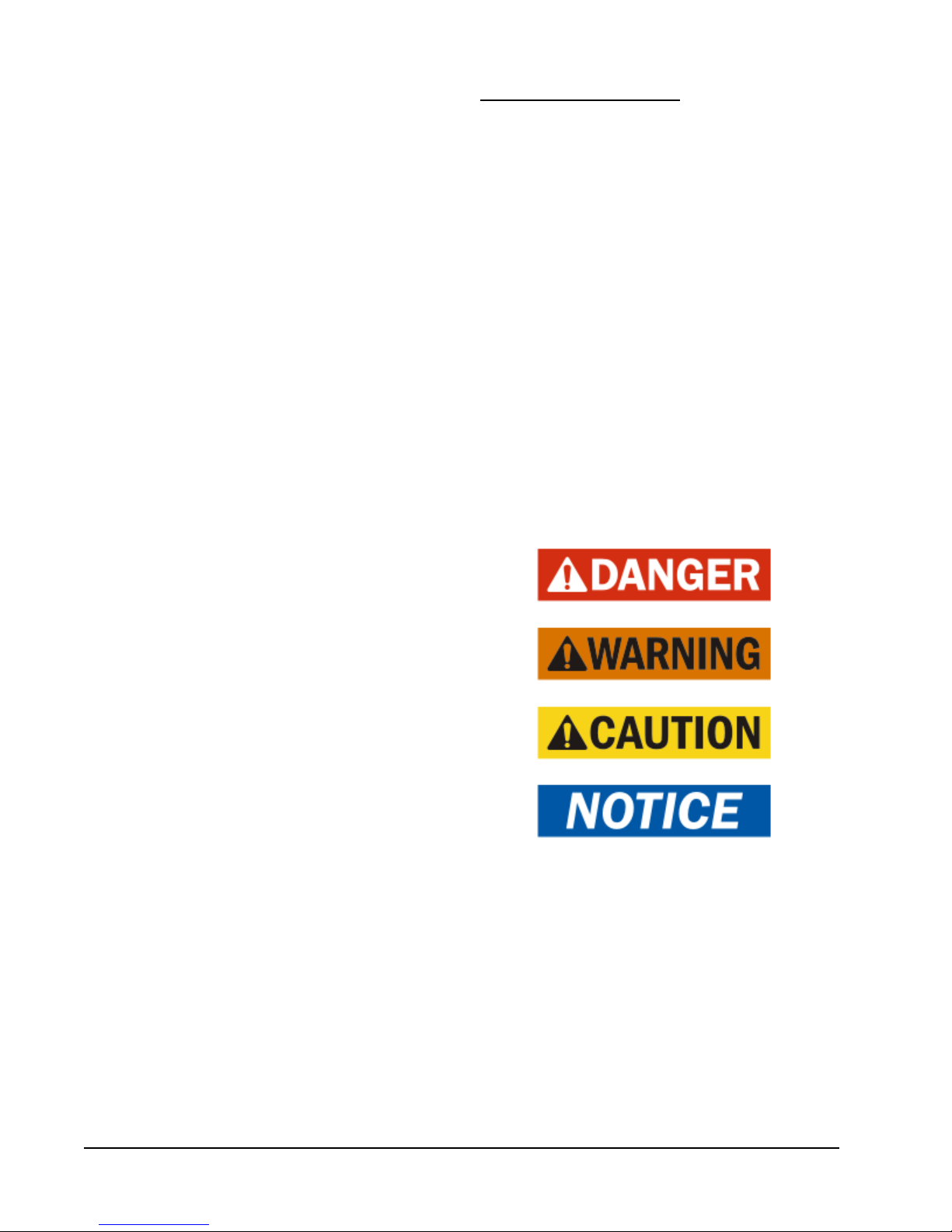
ANSI Z535.5 Definitions:
DANGER: Indicate[s] a hazardous situation which, if
not avoided, will result in death or serious injury. The
signal word “DANGER” is to be limited to the most
extreme situations. DANGER [signs] should not be used
for property damage hazards unless personal injury risk
appropriate to these levels is also involved.
WARNING: Indicate[s] a hazardous situation which,
if not avoided, could result in death or serious injury.
WARNING [signs] should not be used for property
damage hazards unless personal injury risk appropriate
to this level is also involved.
CAUTION: Indicate[s] a hazardous situation which, if
not avoided, could result in minor or moderate injury.
CAUTION [signs] without a safety alert symbol may be
used to alert against unsafe practices that can result in
property damage only.
NOTICE: [this header is] preferred to address practices
not related to personal injury. The safety alert symbol
shall not be used with this signal word. As an
alternative to “NOTICE” the word “CAUTION” without
the safety alert symbol may be used to indicate a
message not related to personal injury.
Manual 2100-665D
Page 4 of 26
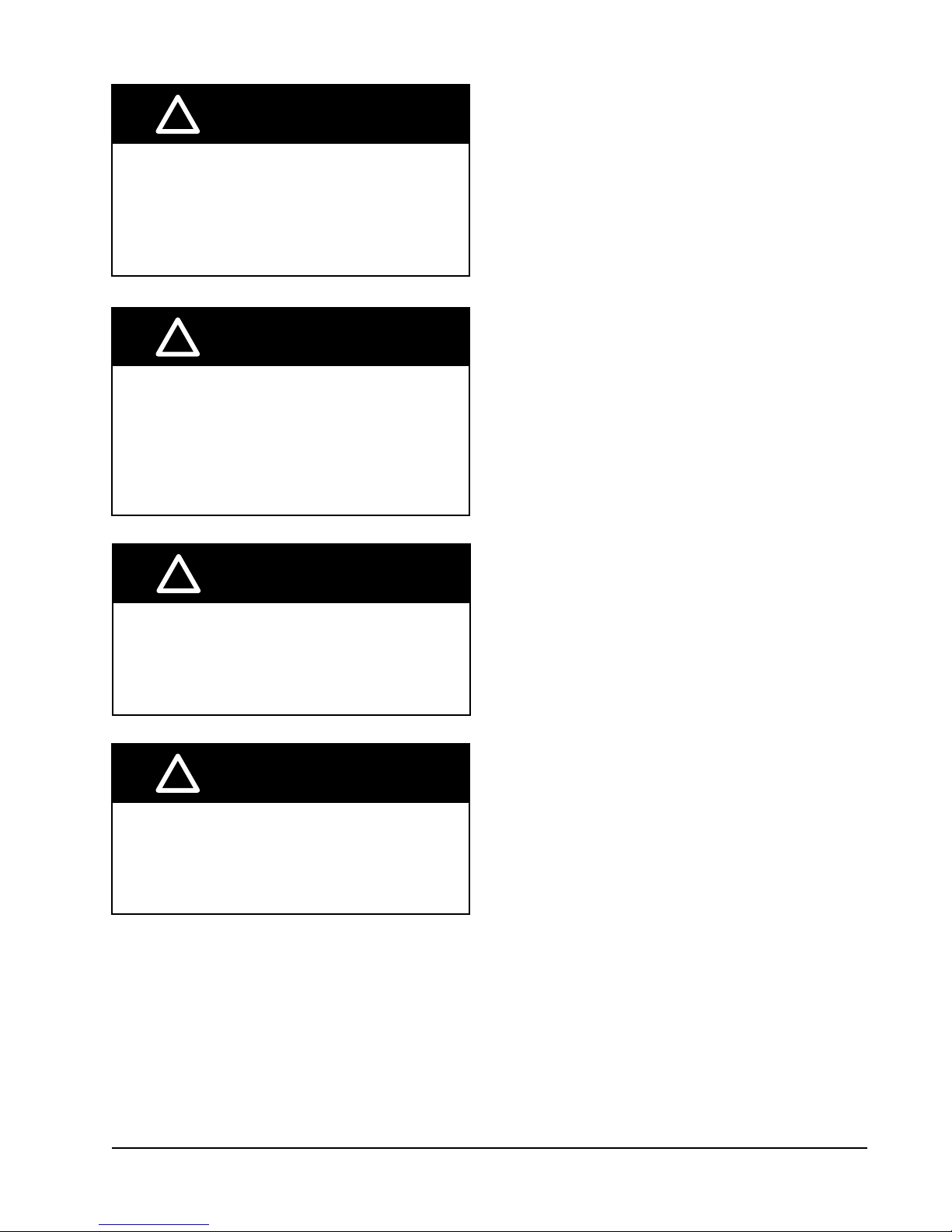
!
WARNING
Electrical shock hazard.
Have a properly trained individual perform
these tasks.
Failure to do so could result in electric shock
or death.
!
WARNING
Fire hazard.
Maintain minimum 1/4" clearance between the
supply air duct and combustible materials in
the rst 3' feet of ducting.
Failure to do so could result in re causing
damage, injury or death.
!
WARNING
Heavy item hazard.
Use more than one person to handle unit.
Failure to do so could result in unit damage or
serious injury.
!
CAUTION
Cut hazard.
Wear gloves to avoid contact with sharp
edges.
Failure to do so could result in personal injury.
Manual 2100-665D
Page 5 of 26
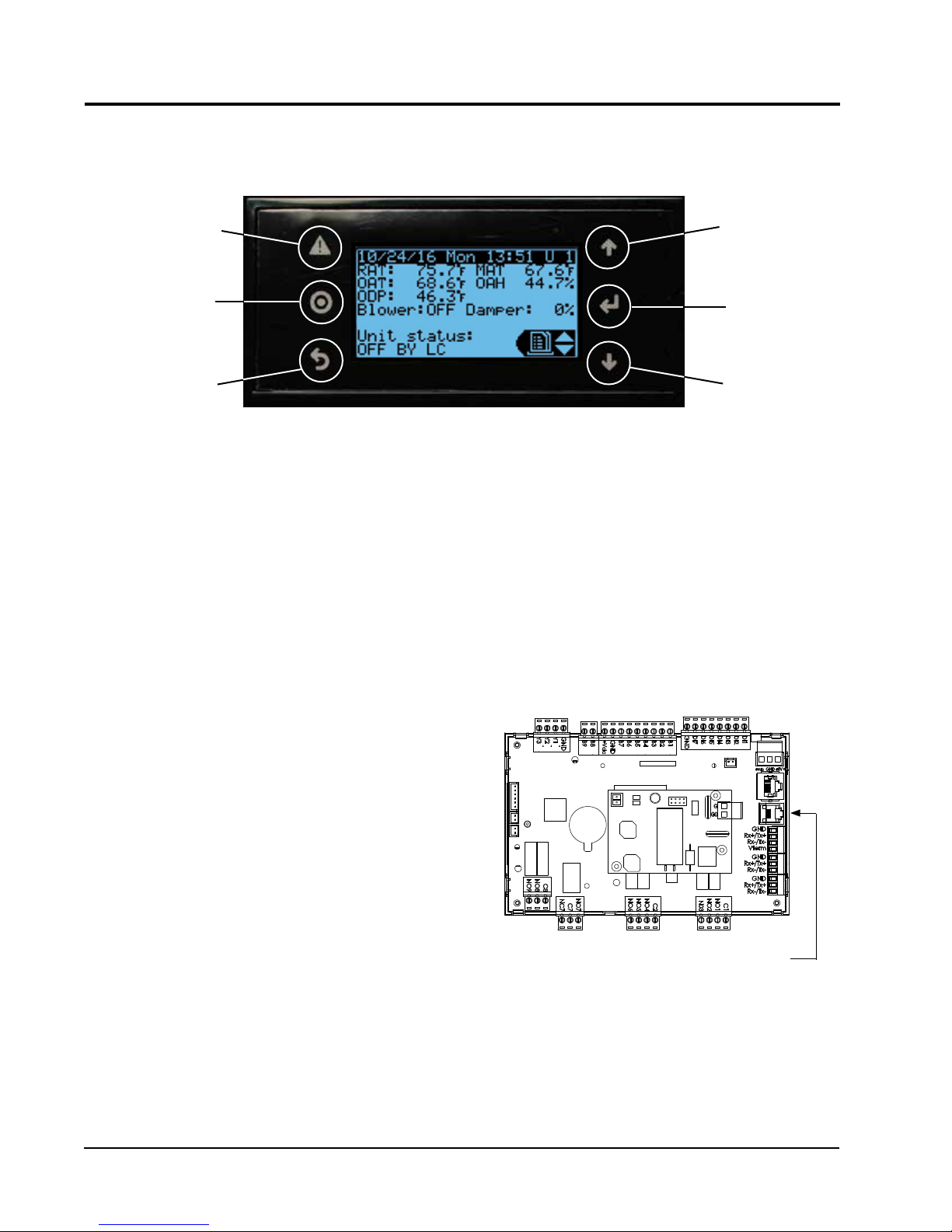
USING THE TEC-EYE
TEC-EYE (Bard P/N 8301-059) Display and Interface (Status Screen Shown)
TM
FIGURE 2
ALARM KEY
MENU KEY
ESCAPE KEY
ALARM KEY
Allows viewing of active alarms
Silences audible alarms
Resets active alarms
MENU KEY
Allows entry to Main Menu
ESCAPE KEY
Returns to previous menu level
Cancels a changed entry
TEC-EYE Hand-Held Diagnostic Tool
The microprocessor control used in the MULTI-TEC
wall-mount air conditioners allows for complete control
and monitoring through the use of the provided TECEYE hand-held monitor. This comprehensive service
tool utilizes the latest in state-of-the-art technology
including a large, easy-to-read backlit LCD graphic
display.
The menu driven interface provides users the ability
to scroll through two menu levels: Quick Menu and
Main Menu. The menus permit the user to easily view,
control and configure the unit.
The controller is completely programmed at the factory;
the default setpoints and their ranges are easily viewed
and adjusted from the TEC-EYE display. The program
and operating parameters are permanently stored
on FLASH-MEMORY in case of power failure. The
controller is designed to manage temperature levels to
a user-defined setpoint via control output signals to the
wall mount air conditioning system.
The TEC-EYE connects to the wall-mount unit control
board via an RJ11 modular phone connector as shown
in Figure 3.
UP KEY
ENTER KEY
DOWN KEY
UP KEY
Steps to next screen in the display menu
Changes (increases) the value of a modifiable field
ENTER KEY
Accepts current value of a modifiable field
Advances cursor
DOWN KEY
Steps back to previous screen in the display menu
Changes (decreases) the value of a modifiable field
FIGURE 3
TEC-EYE Connection to Unit Control
Modular Phone Connector for
TEC-EYE Hand-Held Diagnostic Tool
When not being used, the TEC-EYE hand-held
diagnostic tool should be stored inside or near the
LC6000 controller. Do not let the TEC-EYE leave the
shelter.
Manual 2100-665D
Page 6 of 26
TEC-EYE Menu Structure
Quick Menu
Data Log
Unit Information
Setpoints
Main Menu
System Configuration
Advanced System Configuration
I/O Configuration
On/Off
Alarm Logs
Settings
Logout
In addition to the menu structure above, there are also
Status and Alarm screens.
TEC-EYE Acronyms
MAT – Mixed air temperature
RAT – Return air temperature
OAT – Outdoor air temperature
OAH – Outdoor air humidity
Blower – Indoor Blower Status
Damper – Free cooling damper position status
C1 – Compressor activate status
H1 – Heater Stage 1 status
H2 – Heater Stage 2 status
ODP – Calculated outdoor dew point
FC – Free cooling status
RN – Component run time in minutes in last hour
ST – Number of start requests in last hour
Status Screen
The Status screen is the default start-up screen and
also the return screen after 5 minutes of no activity.
The screen can be accessed any time by pressing the
ESCAPE button repeatedly.
The wall-mount unit address is displayed in the upper
right corner on the Status screen (see Figure 2). The
Status screen also shows the current date, time, return
air temperature, mixed air temperature, outdoor air
temperature, outdoor humidity and outdoor dewpoint
conditions. Blower, damper and unit status are also
displayed. See Table 1 for MULTI-TEC wall-mount unit
status messages.
The Quick Menu is displayed in the bottom right corner
of the status screen (see Figure 2). Data Log, Unit
Information and Setpoints are available through the
Quick Menu. Pressing the UP or DOWN keys while on
the Status screen will change the Quick Menu icon
displayed (see Figure 4). Press the ENTER key when
the desired icon is displayed.
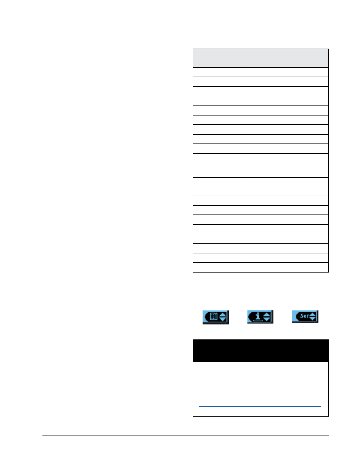
TABLE 1
Wall-Mount Unit Status Messages
Message Description
Stand Alone Orphan Mode Standby
th-TUNE Online th-TUNE Standby
LC Online LC Standby
Cont. Blower Continuous Blower Active
Off by th-TUNE Unit off by th-TUNE
Freecooling Freecooling Active
Optimized Cool Optimized Cooling Active
Cooling Cooling Active
Heating Heating Active
Mechanical Dehumidification or
Active Dehum
Passive Dehum
Self Test Self Test Running
Off by Alarm Unit Off by Alarm Condition
Off by BMS Unit Off by BMS
Off by LC Unit Off by LC Master
Off by Keypad Unit Off by Keypad
Emergency Vent. Emergency Vent Mode Active
Emergency Cool Emergency Cool Mode Active
Emergency Off Emergency Off Mode Active
Electric Reheat Dehumidification
Active
Economizer Disable/Enhanced
Latent Removal (if available)
FIGURE 4
Quick Menu Icons
Data Log Unit Information
Setpoints
NOTICE
It is important to check the software version
during installation to ensure that the latest
version has been installed. Current software
versions, change log and installation
instructions are available on the Bard website at
http://www.bardhvac.com/software-download/
Manual 2100-665D
Page 7 of 26
Quick Menu
Setpoints
If at any time the unit(s) loses communication with the
LC6000 controller, the unit(s) will go to stand alone
mode. The setpoints are synced with the LC6000 when
communication is established. The unit will save and
control to these values until communication is reestablished.
To change the cooling and heating setpoints:
1. From the Status screen, press UP or DOWN key
until Quick Menu displays Setpoints icon. Press
ENTER key.
2. Press ENTER key to scroll to the selected choice
(see Figure 5).
3. Press UP or DOWN key on desired value until value
displays correctly.
4. Press ENTER key to submit value and move to next
parameter.
5. Press ESCAPE key until Main Menu screen is
displayed.
FIGURE 5
Cooling and Heating Setpoints
Information
These screens show unit demand, wall-mount unit
status, serial/model number, hours, run hours, averages
and software version information.
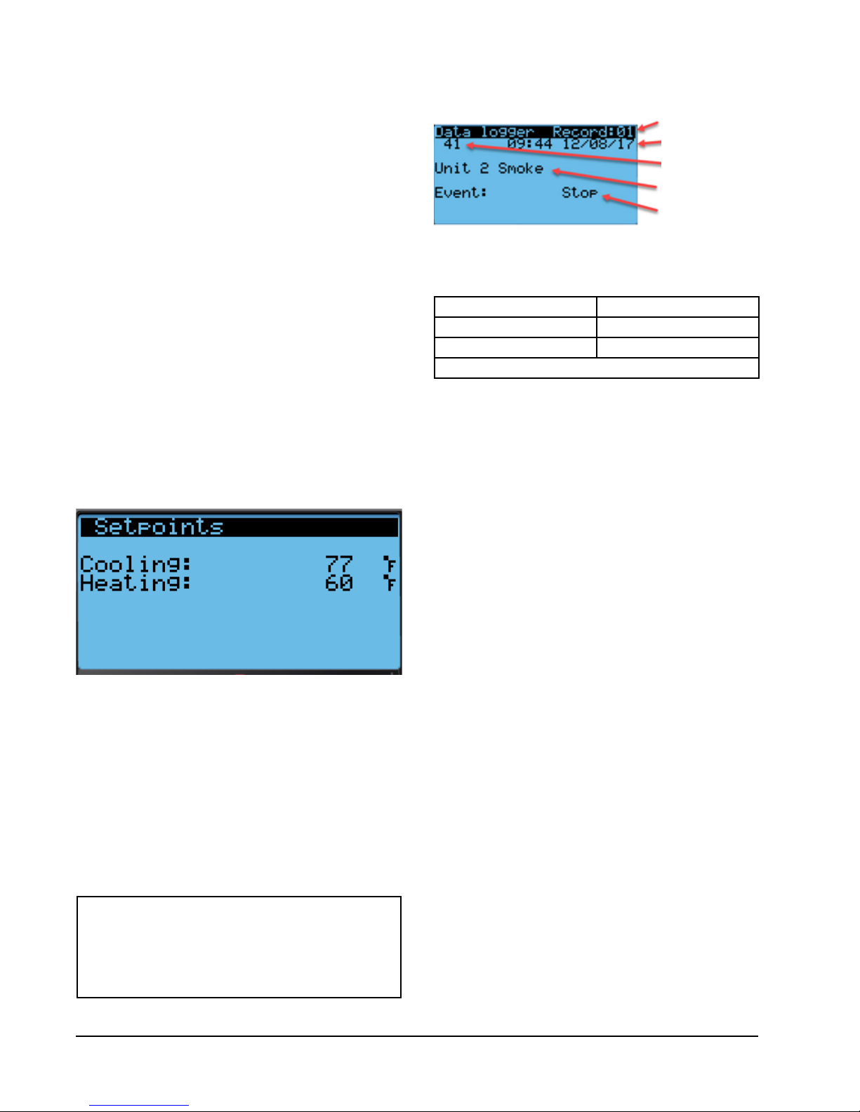
Data (Alarm) Log
The alarm log screens show a log of each alarm (see
Figure 6. There will be a log for when alarm occurred
and if the alarm auto clears, it will show when the
alarm cleared. See page 11 for instructions on clearing
the alarm logs.
NOTE
Screenshots shown in this manual reflect
default settings (when applicable).
FIGURE 6
Alarm Log Screen Breakdown
Alarm Log Number
Alarm Date/Time
Alarm Index
Number
Alarm Description
Alarm Event Type
(Start/Stop)
TABLE 2
LC1000/TEC-EYE Passwords (Defaults)
User 2000
Technician 1313
Engineer 9254
Use UP or DOWN keys and ENTER key to enter password
Menu Screens and Password Levels
A System Config: User (2000)
B Adv Sys Config: Technician (1313)
C I-O Config: Technician (1313)
D On/Off: User (2000)
E Alarm Logs: User (2000)
F Settings
Date/Time: Technician (1313)
Language: User (2000)
Network Config: Technician (1313)
Serial Ports: Technician (1313)
Initialization
Clear Logs: User (2000)
System Default: Engineer (9254)
Restart: User (2000)
Parameter Config: Engineer (9254)
Alarm Export: User (2000)
G Logout: Used to log out of the current password
level. Entering back into the menu requires
password.
Additional Features
Model/Serial Number Retain Feature
Model numbers and serial numbers will be retained
through most software updates. It still remains good
practice to verify the software version, model numbers
and serial numbers of any wall-mount unit after a
software update, as some functionality of the MULTITEC wall-mount unit require a specific model number.
Manual 2100-665D
Page 8 of 26
 Loading...