

Page 1
INSTALLATION INSTRUCTIONS
WALL MOUNTED PACKAGED
AIR CONDITIONER
Models:
W18AA-A
W24AA-A
W24AA-B
W24AA-C
W24AA-D
W24AA-F
W30AA-A
W30AA-B
W30AA-C
W30AA-D
W30AA-F
W36AA-A
W36AA-B
W36AA-C
W36AA-D
W36AA-E
W36AA-F
W42AA-A
W42AA-B
W42AA-C
W42AA-E
W42AA-F
W48AA-A
W48AA-B
W48AA-C
W48AA-E
W48AA-F
W60AA-A
W60AA-B
W60AA-C
W60AA-E
W60AA-F
W72AB-A
W72AB-B
W72AB-C
W72AB-F
W18LA-A
W24LA-A
W24LA-B
W24LA-F
W30LA-A
W30LA-B
W30LA-C
W30LA-F
W36LA-A
W36LA-B
W36LA-C
W36LA-F
W42LA-A
W42LA-B
W42LA-C
W42LA-F
W48LA-A
W48LA-B
W48LA-C
W48LA-F
W60LA-A
W60LA-B
W60LA-C
W60LA-F
W72LB-A
W72LB-B
W72LB-C
W72LB-F
W30AADA
W30AADB
W30AADC
W36AADA
W36AADB
W36AADC
W42AADA
W42AADB
W42AADC
W48AADA
W48AADB
W48AADC
W60AADA
W60AADB
W60AADC
Bard Manufacturing Company, Inc.
Bryan, Ohio 43506
www.bardhvac.com
Manual: 2100-640F
Supersedes: 2100-640E
Date: 3-21-18
Page 1 of 32
Page 2

CONTENTS
Getting Other Information and Publications .... 3
Wall Mount General Information .........................4
Air Conditioner Wall Mount Model Nomenclature ..... 4
Shipping Damage ................................................. 4
General ............................................................... 4
Duct Work ........................................................... 5
Filters ................................................................. 5
Fresh Air Intake ................................................... 5
Condensate Drain ................................................ 5
Installation ............................................................... 6
Wall Mounting Information .................................... 6
Mounting the Unit ................................................ 6
Clearances Required ............................................. 6
Minimum Clearances ............................................ 6
Wiring – Main Power ........................................... 15
Wiring – Low Voltage Wiring ................................. 15
Figures
Figure 1 Fresh Air Damper .................................. 5
Figure 2 Unit Dimensions ................................... 7
Figure 3A Mounting Instructions
Figure 3B
Figure 3C
Mounting Instructions –
Mounting Instructions –
Figure 3D Mounting Instructions –
W18, 24
W30, 36
W42, 48 ..............
W60, 72 ..............
............ 8
................9
10
11
–
Figure 4 Electric Heat Clearance ....................... 12
Figure 5 Wall Mounting Instructions .................. 13
Figure 6 Wall Mounting Instructions .................. 13
Figure 7 Common Wall Mounting Installations .... 14
Figure 8 Programmable Thermostat
Connections ....................................... 17
Figure 9 Non-Programmable Thermostat
Connections ....................................... 18
Figure 10 Motor Connections .............................. 22
Figure 11 Motor Connections .............................. 23
Figure 12 Fan Blade Setting ............................... 24
Start Up ................................................................... 19
General ............................................................. 19
Topping Off System Charge ................................. 19
Safety Practices ................................................. 19
Important Installer Note ...................................... 19
High Pressure Switch .......................................... 20
Three Phase Scroll Compressor ............................ 20
Phase Monitor .................................................... 20
Condenser Fan Operation .................................... 20
Service Hints ..................................................... 20
Sequence of Operation ........................................ 20
Vent Connection Plug .......................................... 20
Compressor Control Module ................................. 21
Pressure Service Ports ........................................ 21
Service ..................................................................... 22
Troubleshooting Nidec SelecTech Series ECM
Motors ............................................................... 22
Fan Blade Setting Dimensions ............................. 24
R-410A Refrigerant Charge ................................. 24
Removal of Fan Shroud ....................................... 24
Tables
Table 1 Wall Thermostats ................................ 16
Table 2 Humidity Controls ............................... 16
Table 3 CO
Controller ..................................... 16
2
Table 4 Thermostat Wire Size ........................... 16
Table 5 Fan Blade Dimensions ......................... 24
Table 6 Cooling Pressure ................................. 25
Table 7 Electrical Specifications W**AA ........... 26
Table 8 Electrical Specifications W**LA ............ 27
Table 9 Recommended Airflow ......................... 28
Table 10 Indoor Blower Performance .................. 28
Table 11 Maximum ESP Electric Heat Only ......... 28
Table 12 Electric Heat ...................................... 29
Table 13 Vent and Control Options ..................... 30
Table 14A Optional Accessories
Table 14B Optional Accessories
– Right Hand ....... 31
– Left Hand .............32
Manual 2100-640F
Page 2 of 32
Page 3

GETTING OTHER INFORMATION AND PUBLICATIONS
These publications can help when installing the
furnace. They can usually be found at the local library
or purchased directly from the publisher. Be sure to
consult the current edition of each standard.
National Electrical Code ...................... ANSI/NFPA 70
Standard for the Installation ..............ANSI/NFPA 90A
of Air Conditioning and Ventilating Systems
Standard for Warm Air .......................ANSI/NFPA 90B
Heating and Air Conditioning Systems
Load Calculation for ......................... ACCA Manual J
Residential Winter and Summer Air Conditioning
Duct Design for Residential ............... ACCA Manual D
Winter and Summer Air Conditioning and Equipment
Selection
For more information, contact these publishers:
ACCA Air Conditioning Contractors of America
1712 New Hampshire Ave. N.W.
Washington, DC 20009
Telephone: (202) 483-9370
Fax: (202) 234-4721
ANSI American National Standards Institute
11 West Street, 13th Floor
New York, NY 10036
Telephone: (212) 642-4900
Fax: (212) 302-1286
ASHRAE American Society of Heating, Refrigeration
and Air Conditioning Engineers, Inc.
1791 Tullie Circle, N.E.
Atlanta, GA 30329-2305
Telephone: (404) 636-8400
Fax: (404) 321-5478
NFPA National Fire Protection Association
Batterymarch Park
P.O. Box 9101
Quincy, MA 02269-9901
Telephone: (800) 344-3555
Fax: (617) 984-7057
Manual 2100-640F
Page 3 of 32
Page 4
WALL MOUNT GENERAL INFORMATION
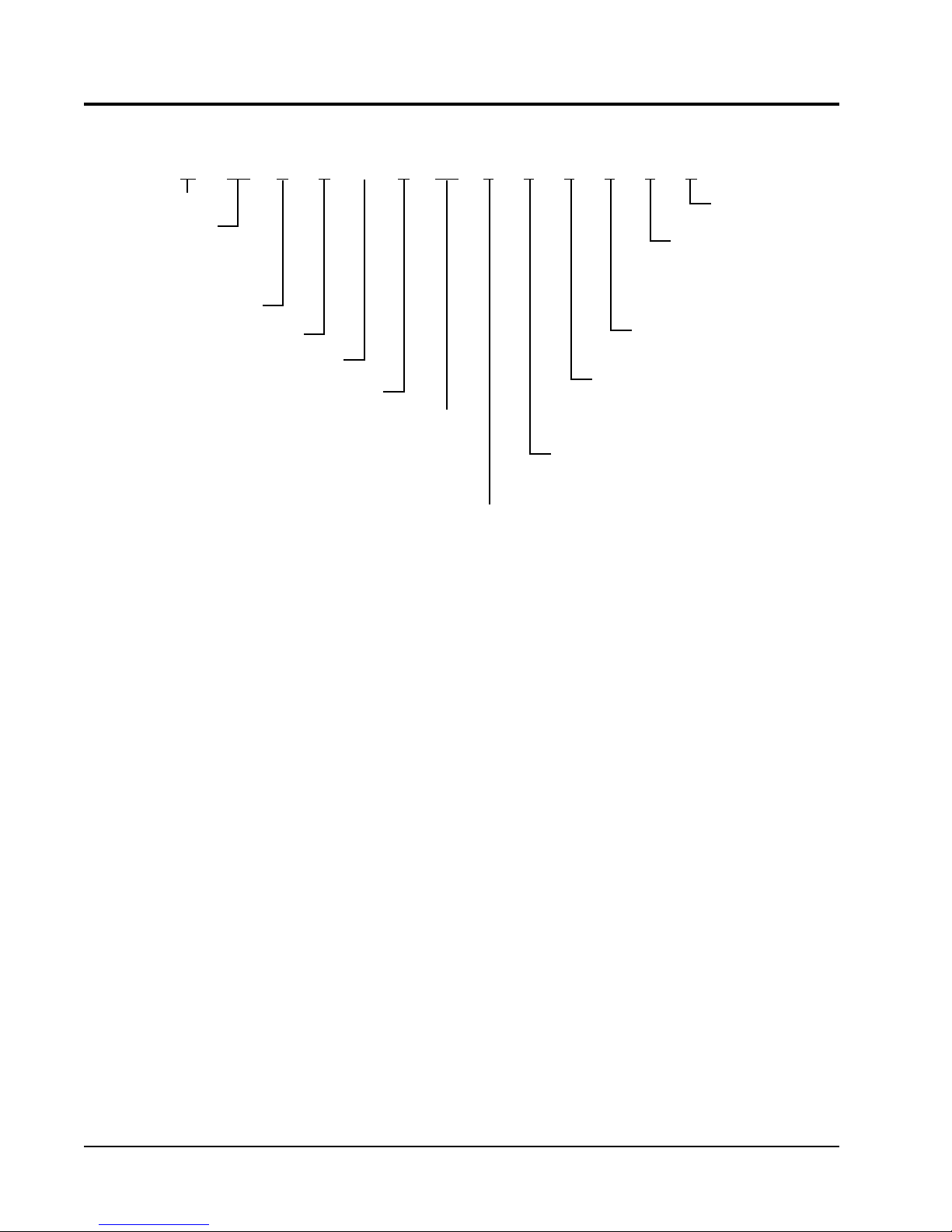
AIR CONDITIONER WALL MOUNT MODEL NOMENCLATURE
W 42 A A – A 10 X X X X X A
MODEL SERIES
CAPACITY
18 – 1½ Ton
24 – 2 Ton
30 – 2½ Ton
36 – 3 Ton
Insert “D” for dehumidification with hot gas reheat.
Reference Form 7960-736 for complete details.
NOTE: Vent options X, B and M are without exhaust capability. May require separate field-supplied barometric relief in building.
SHIPPING DAMAGE
Upon receipt of equipment, the carton should be
checked for external signs of shipping damage. If
damage is found, the receiving party must contact
the last carrier immediately, preferably in writing,
requesting inspection by the carrier’s agent.
42 – 3½ Ton
48 – 4 Ton
60 – 5 Ton
72 – 6 Ton
A – Right Hand
L – Left Hand
A – 230/208/60/1
B – 230/208/60/3
C – 460/60/3
D – 240/220/50/1
REVISION
SPECIALTY PRODUCTS
(Non-Standard)
VOLTS & PHASE
E – 240/220/50/3
or 220/200/50/3
F – 415/380/50/3
X – Barometric Fresh Air Damper (Standard)
B – Blank-off Plate
M – Motorized Fresh Air Damper
V – Commercial Ventilator - Motorized with Exhaust
OUTLET OPTIONS
X – Front (Standard)
T – Top Outlet (W30A, W36A only)
COLOR OPTIONS
X – Beige (Standard)
1 – White
KW
VENTILATION OPTIONS
4 – Buckeye Gray
5 – Desert Brown
FILTER OPTIONS
X – 1" Throwaway (Standard)
W – 1" Washable
P – 2" Pleated
R – Energy Recovery Ventilator - Motorized with Exhaust
Y – Full Flow Economizer - DB Temp.
Z – Full Flow Economizer - Enthalpy
These instructions explain the recommended method
to install the air cooled self-contained unit and the
electrical wiring connections to the unit.
These instructions and any instructions packaged with
any separate equipment required to make up the entire
air conditioning system should be carefully read before
CONTROL MODULES
(See Spec. Sheet S3502)
COIL OPTIONS
X – Standard
1 – Phenolic Coated Evaporator
2 – Phenolic Coated Condenser
3 – Phenolic Coated Evaporator
and Condenser
8 – Dark Bronze
A – Aluminum
S – Stainless Steel
beginning the installation. Note particularly “Starting
GENERAL
Procedure” and any tags and/or labels attached to the
equipment.
The equipment covered in this manual is to be installed
by trained, experienced service and installation
technicians.
While these instructions are intended as a general
recommended guide, they do not supersede any
national and/or local codes in any way. Authorities
This appliance is not intended for use by persons
(including children) with reduced physical, sensory
or mental capabilities, or lack of experience and
having jurisdiction should be consulted before the
installation is made. See page 3 for information on
codes and standards.
knowledge, unless they have been given supervision or
instruction concerning use of the appliance by a person
responsible for their safety.
Size of unit for a proposed installation should be based
on heat loss calculation made according to methods of
Air Conditioning Contractors of America (ACCA). The
Children should be supervised to ensure that they do
not play with the appliance.
The refrigerant system is completely assembled and
charged. All internal wiring is complete.
The unit is designed for use with or without duct work.
Flanges are provided for attaching the supply and
return ducts.
air duct should be installed in accordance with the
Standards of the National Fire Protection Association
for the Installation of Air Conditioning and Ventilating
Systems of Other Than Residence Type, NFPA No.
90A, and Residence Type Warm Air Heating and Air
Conditioning Systems, NFPA No. 90B. Where local
regulations are at a variance with instructions, installer
should adhere to local codes.
Manual 2100-640F
Page 4 of 32
Page 5
DUCT WORK
FRESH AIR INTAKE
All duct work, supply and return, must be properly
sized for the design airflow requirement of the
equipment. Air Conditioning Contractors of America
(ACCA) is an excellent guide to proper sizing. All duct
work or portions thereof not in the conditioned space
should be properly insulated in order to both conserve
energy and prevent condensation or moisture damage.
Refer to Maximum ESP of operation Electric Heat Table
11 on page 28.
Design the duct work according to methods given by
the Air Conditioning Contractors of America (ACCA).
When duct runs through unheated spaces, it should be
insulated with a minimum of one inch of insulation.
Use insulation with a vapor barrier on the outside of the
insulation. Flexible joints should be used to connect the
duct work to the equipment in order to keep the noise
transmission to a minimum.
Models W18 – W24 are approved for 0" clearance to
the supply duct. For model series W30, W36, W42,
W48, W60 and W72, a 1/4" clearance to combustible
material for the first 3' of duct attached to the outlet
air frame is required. See wall mounting instructions
on page 6 and Figures 3 and 4 (pages 8 – 12) for
further details.
All units are built with fresh air inlet slots punched in
the service door.
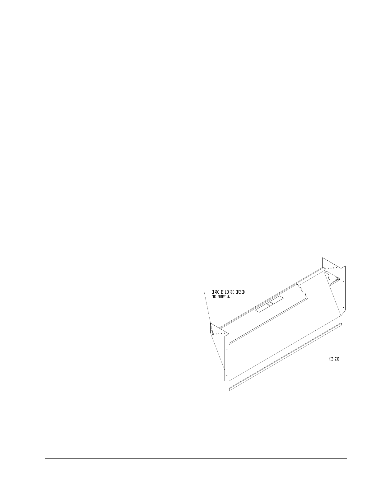
If the unit is equipped with a fresh air damper
assembly, the assembly is shipped already attached
to the unit. The damper blade is locked in the
closed position. To allow the damper to operate, the
maximum and minimum blade position stops must be
installed (see Figure 1).
All capacity, efficiency and cost of operation
information is based upon the fresh air blank-off plate
in place and is recommended for maximum energy
efficiency.
The blank-off plate is available upon request from the
factory and is installed in place of the fresh air damper
shipped with each unit.
CONDENSATE DRAIN
A plastic drain hose extends from the drain pan at
the top of the unit down to the unit base. There are
openings in the unit base for the drain hose to pass
through. In the event the drain hose is connected to
a drain system of some type, it must be an open or
vented type system to assure proper drainage.
Ducts through the walls must be insulated and all joints
taped or sealed to prevent air or moisture entering the
wall cavity.
Some installations may not require any return air duct.
A metallic return air grille is required with installations
not requiring a return air duct. The spacing between
louvers on the grille shall not be larger than 5/8".
Any grille that meets with 5/8" louver criteria may
be used. It is recommended that Bard Return Air
Grille Kit RG2 through RG5 or RFG2 through RFG5
be installed when no return duct is used. Contact
distributor or factory for ordering information. If using
a return air filter grille, filters must be of sufficient size
to allow a maximum velocity of 400 fpm.
NOTE: If no return air duct is used, applicable
installation codes may limit this cabinet to
installation only in a single story structure.
FILTERS
A 1" throwaway filter is standard with each unit. The
filter slides into position making it easy to service. This
filter can be serviced from the outside by removing the
filter access panel. A 1" washable filter and 2" pleated
filter are also available as optional accessories. The
internal filter brackets are adjustable to accommodate
the 2" filter by bending two tabs down on each side of
the filter support bracket.
FIGURE 1
Fresh Air Damper
Manual 2100-640F
Page 5 of 32
Page 6

INSTALLATION
WALL MOUNTING INFORMATION
1. Two holes for the supply and return air openings
must be cut through the wall as shown in Figures
Figures 3A – D (pages 8 – 11).
WARNING
2. On wood frame walls, the wall construction must
be strong and rigid enough to carry the weight of
the unit without transmitting any unit vibration.
3. Concrete block and brick walls must be thoroughly
inspected to insure that they are capable of
carrying the weight of the installed unit.
MOUNTING THE UNIT
1. These units are secured by wall mounting brackets
which secure the unit to the outside wall surface at
both sides. A bottom mounting bracket, attached
to skid for shipping, is provided for ease of
installation, but is not required.
2. The supply air duct flange and the first 3' of supply
air duct require a minimum of 1/4" clearance
to combustible material for model series W30,
W36, W42, W48, W60 and W72. However, it
is generally recommended that a 1" clearance is
used for ease of installation and maintaining the
required clearance to combustible material. See
Figures 3A – D for details on opening sizes.
3. Locate and mark lag bolt locations and bottom
mounting bracket location (see Figures 3A – D).
4. Mount bottom mounting bracket.
Failure to provide the 1/4" clearance between
the supply duct and a combustible surface
for the rst 3' of duct can result in re causing
damage, injury or death.
6. Position unit in opening and secure with 5/16 lag
bolts; use 7/8" diameter flat washers on the lag
bolts.
7. Secure rain flashing to wall and caulk across entire
length of top (see Figures 3A – D).
8. For additional mounting rigidity, the return air
and supply air frames or collars can be drilled
and screwed or welded to the structural wall itself
(depending upon wall construction). Be sure to
observe required clearance if combustible wall.
9. On side-by-side installations, maintain a minimum
of 20" clearance on right side to allow access to
control panel and heat strips and proper airflow
to the outdoor coil. Additional clearance may be
required to meet local or national codes.
5. Hook top rain flashing, attached to front-right of
supply flange for shipping, under back bend of top.
Clearances Required for Service Access and
Adequate Condenser Airflow
LEFT
MODELS
W18A, W24A, W30A, W36A 15" 20" 10'
W18L, W24L, W30L, W36L 20" 15" 10'
W42A, W48A, W60A, W72A 20" 20" 10'
W42L, W48L, W60L, W72L 20" 20" 10'
NOTE: For side-by-side installation of two W**A models there must
be 20" between units. This can be reduced to 15" by using a W**L
model (left side compressor and controls) for the left unit and W**A
(right side compressor and controls) for right unit.
See Specifications Sheet S3502.
Manual 2100-640F
Page 6 of 32
SIDE
RIGHT
SIDE
DISCHARGE
SIDE
Minimum Clearances Required to
Combustible Materials
MODELS
W18A, L
W24A, L
W30A, L
W36A, L
W42A, L
W48A, L
W60A, L
W72A, L
SUPPLY AIR DUCT
FIRST 3'
0" 0"
1/4" 0"
1/4" 0"
CABINET
Page 7
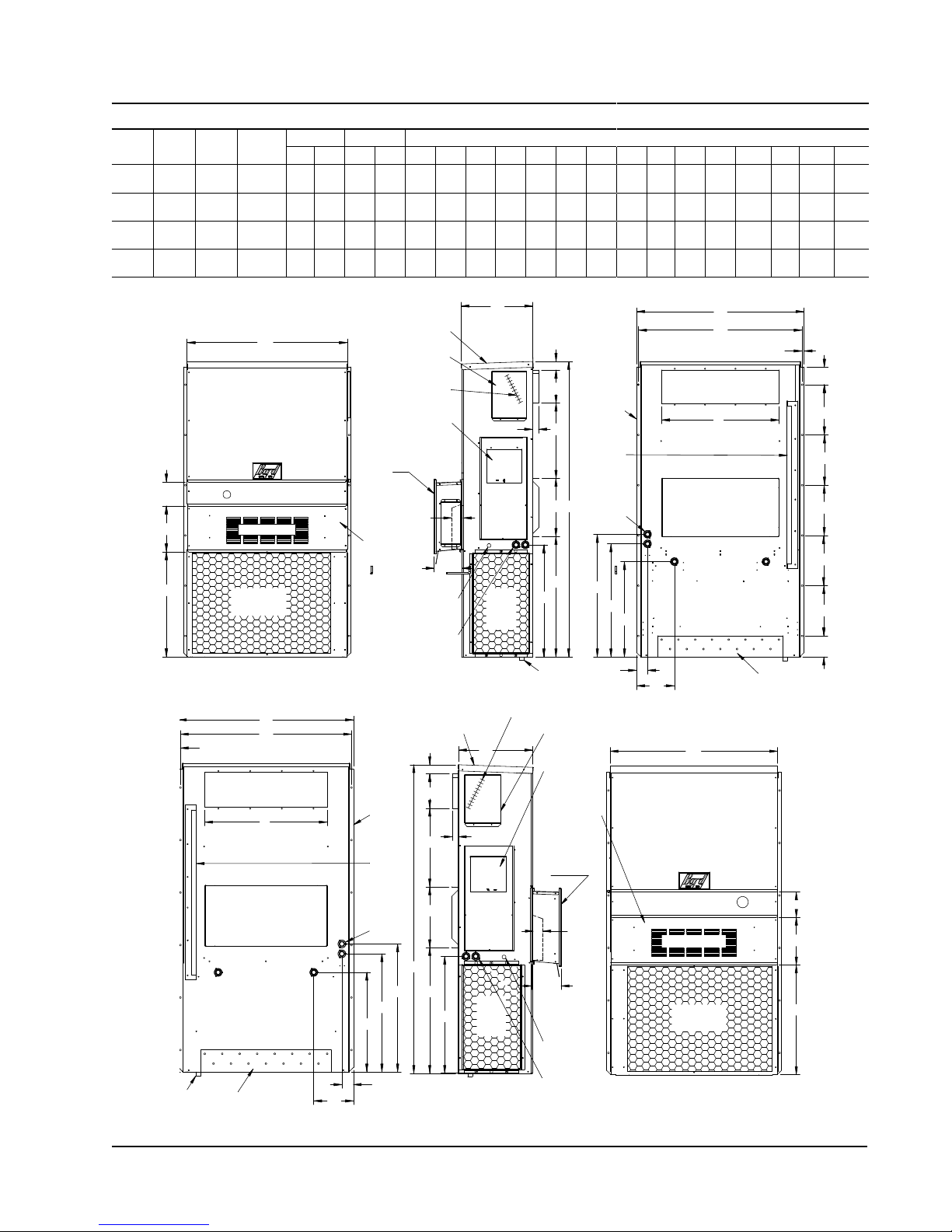
FIGURE 2
Dimensions of Basic Unit for Architectural and Installation Requirements (Nominal)
WIDTH
DEPTH
MODEL
W18*A
W24*A
W30*A
W36*A
W42*A
W48*A
W60*A
W72*B
(W)
33.300 17.125 74.563 7.88 19.88 11.88 19.88 35.00 10.88 29.75 20.56 30.75 32.06 33.25 31.00 2.63 34.13 26.06 10.55 4.19 12.00 9.00
38.200 17.125 74.563 7.88 27.88 13.88 27.88 40.00 10.88 29.75 17.93 30.75 32.75 33.25 31.00 2.75 39.13 26.75 9.14 4.19 12.00 9.00
42.075 22.432 84.875 9.88 29.88 15.88 29.88 43.88 13.56 31.66 30.00 32.68 26.94 34.69 32.43 3.37 43.00 23.88 10.00 1.44 16.00 1.88
42.075 22.432 93.000 9.88 29.88 15.88 29.88 43.88 13.56 37.00 30.00 40.81 35.06 42.81 40.56 3.37 43.00 31.00 10.00 1.44 16.00 10.00
HEIGHT
(D)
All dimensions are in inches. Dimensional drawings are not to scale.
W**A*
RIGHT
UNIT
Filter Access Panel
5.88
F
G
1
Ventilation Air
Condenser
Air Outlet
Front View
.44
Supply Air Opening
W**L*
LEFT
UNIT
Return Air Opening
Bottom
Installation
Bracket
SUPPLY RETURN
(H)
A B C B E F G I J K L M N O P Q R S T
W
E
O
B
Back View
Q
Rain Hood
C. Breaker/
Disconnect
Access Panel
(Lockable)
Hood for CRV and
ECON models
only
Standard
flush vent
door for nonERV/CRV
Econ.
models
Low Voltage
High Voltage
Side Wall
Mounting
Brackets
(Built In)
Top Rain
Flashing
Shipping
Location
Optional
Electrical
Entrances
H
L
M
P
N
Built In
4° Pitch
Heater
Access
Panel
Electric
Heat
3"
Electrical
Entrance
Electrical
Entrance
Built In
Rain Hood
4° Pitch
2.13
A
I
C
K
7.00
J
D
1.250
Cond.
Air
Inlet
Side View
D
1.250
Cond.
Air
Inlet
Side View
J
Drain
Electric
Heat
Heater
Access
Panel
C. Breaker/
Disconnect
Access Panel
(Lockable)
Standard flush
non-ERV/CRV
Hood for CRV and
ECON models
only
7.000
Low Voltage
Electrical
Entrance
High Voltage
Electrical
Entrance
2.13
Side Wall
A
Mounting
I
C
H
Entrances
K
vent door for
Econ. models
3"
Brackets
(Built In)
Top Rain
Flashing
Shipping
Location
Optional
Electrical
L
M
N
P
Q
Filter Access Panel
Ventilation Air
E
O
Supply Air Opening
B
Return Air Opening
Back View
W
1
Condenser
Air Outlet
Front View
.44
Bottom Installation
Bracket
MIS-3737
R
S
S
S
S
S
T
MIS-3736
5.88
F
G
Manual 2100-640F
Page 7 of 32
Page 8
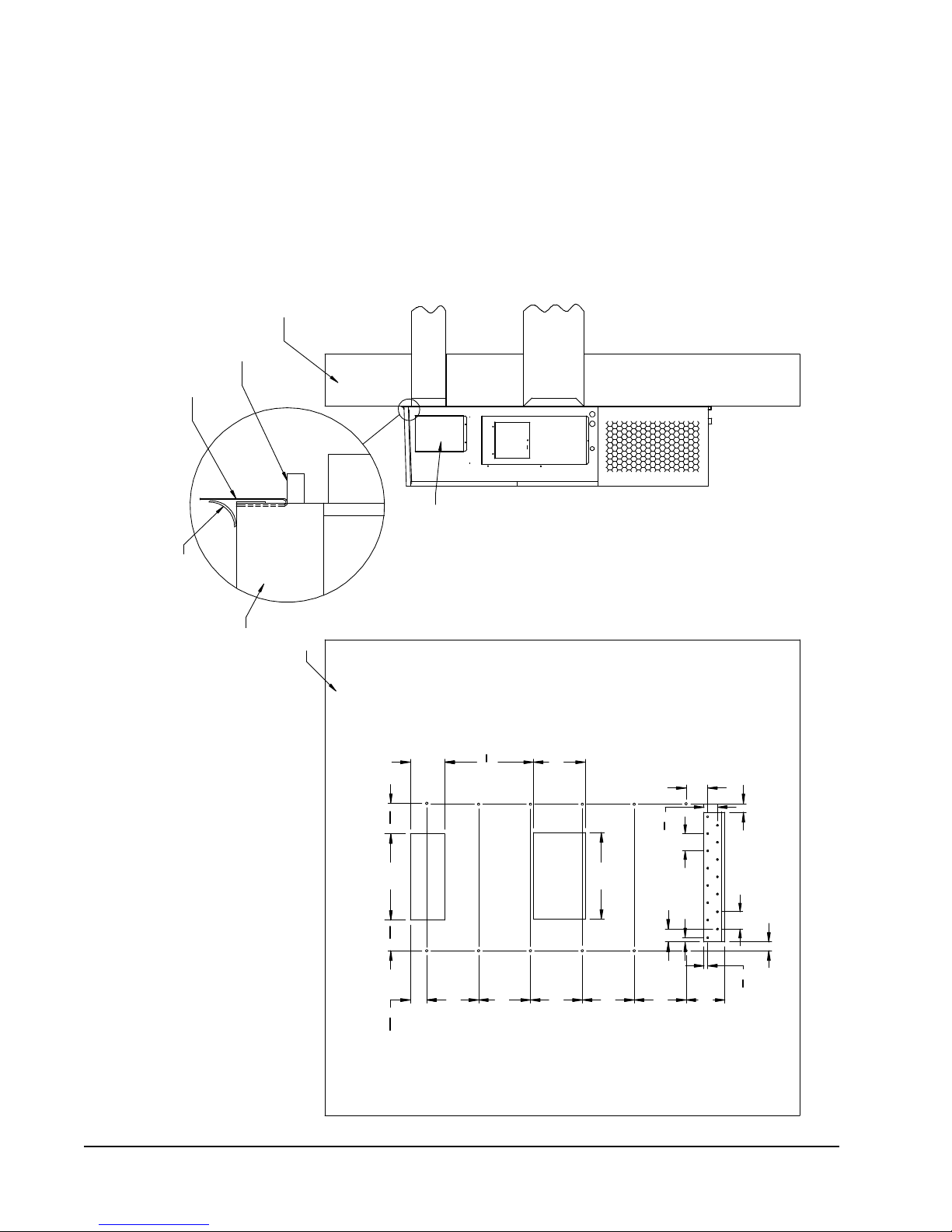
MIS-3157 A
WALL STRUCTURE
FOAM AIR SEAL
SUPPLIED
RAIN FLASHING
FIGURE 3A
SEAL WITH BEAD
OF CAULKING ALONG
ENTIRE LENGTH OF TOP.
TOP
Mounting Instructions
W18AA, W18LA, W24AA, W24LA
NOTES:
RETURN AIR
SUPPLY AIR
DUCT
PANEL
HEATER ACCESS
WALL
"
1
8"
2
20
OPENING
12"
IT IS RECOMMENDED THAT A BEAD OF
SILICONE CAULKING BE PLACED BEHIND
THE SIDE MOUNTING FLANGES AND UNDER
TOP FLASHING AT TIME OF INSTALLATION.
IS ON OPPOSITE (LEFT) SIDE.
CONTROLS AND HEATER ACCESS
J**A UNIT SHOWN, J**L UNIT
5"
"
1
16
"
1
8
3
4"
Typ.
2"
Manual 2100-640F
Page 8 of 32
20"
Supply Opening
" 7
1
16
7
"
13
16
3
12"
12"
20"
Return Opening
12"
12"
1"
3"
12"
4"
Typ.
"
2"
7
8
Wall Opening and Hole Location View Right Side View
9"
Page 9
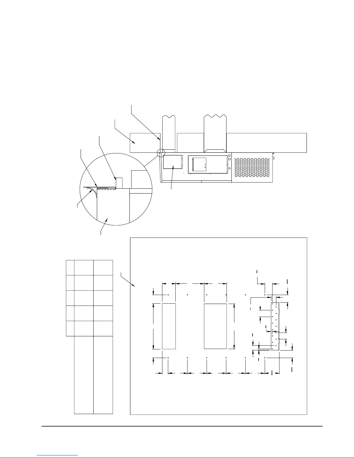
FOUR SIDES OF SUPPLY
Wall Opening and Hole Location View
1/4" MIN. CLEARANCE FROM
COMBUSTIBLE MATERIALSCRECOMMENDED 1" CLEARANCE FROM
REQUIRED DIMENSIONS TO MAINTAIN
COMBUSTIBLE MATERIALS
REQUIRED DIMENSIONS TO MAINTAIN
AIR DUCT IS REQUIRED
1/4" CLEARANCE ON ALL
FROM COMBUSTABLE
MIS-3820
MATERIALS
WALL STRUCTURE
FOAM AIR SEAL
SUPPLIED
RAIN FLASHING
FIGURE 3B
SEAL WITH BEAD
OF CAULKING ALONG
Mounting Instructions
W30AA, W30LA, W36AA, W36LA
ENTIRE LENGTH OF TOP.
ED
17 5/8
3 11/16
TOP
4 7/16
TOP FLASHING AT TIME OF INSTALLATION.
IT IS RECOMMENDED THAT A BEAD OF
THE SIDE MOUNTING FLANGES AND UNDER
SUPPLY AIR
DUCT
RETURN AIR
OPENING
NOTES:
SILICONE CAULKING BE PLACED BEHIND
W**A UNIT SHOWN, W**L UNIT
CONTROLS AND HEATER ACCESS
IS ON OPPOSITE (LEFT) SIDE.
Right Side View
PANEL
HEATER ACCESS
WALL
B
E
14"
"
7
8
4
"
16
11
4
5 3/8
B
8 3/8A9 7/829 7/8
4 5/8 16 7/8
28 3/8
C
A
Supply Opening
Return Opening
28"
C
D
12"
12"
12"
12"
4"
"
Typ.
1
8
3
"
7
8
"
7
8
2
"
7
8
12"
4"
Typ.
"
1
16
9
"
16
11
4
Manual 2100-640F
Page 9 of 32
Page 10
D
16"
16"
16"
16"
16"
1
7
8
"
6
1
2
" 6
1
2
"
2
1
8
"
7
8
"
1"
3"
4"
Typ.
4"
Typ.
6
1
2
"
30"
E
16"
A CC
3
1
8
"
B
Wall Opening and Hole Location View
RETURN AIR
1
REQUIRED DIMENSIONS TO MAINTAIN
1/4" MIN. CLEARANCE FROM
COMBUSTIBLE MATERIALS
REQUIRED DIMENSIONS TO MAINTAIN
29
DUCT
COMBUSTIBLE MATERIALS
A B C DE
30 1/2
10 1/2
6 1/4 1 1/4 29 3/4
32 12 5 1/2
2
NOTES:
WALL STRUCTURE
1
SUPPLY AIR
IT IS RECOMMENDED THAT A BEAD OF
OPENING
Right Side View
RAIN FLASHING
SILICONE CAULKING BE PLACED BEHIND
RECOMMENDED 1" CLEARANCE FROM
THE SIDE MOUNTING FLANGES AND UNDER
TOP FLASHING AT TIME OF INSTALLATION.
TOP.
PANEL
HEATER ACCESS
FOUR SIDES OF SUPPLY
AIR DUCT IS REQUIRED
FROM COMBUSTABLE
WALL
1/4" CLEARANCE ON ALL
MATERIALS
Supply Opening
FOAM AIR SEAL
SUPPLIED
SEAL WITH BEAD
OF CAULKING ALONG
ENTIRE LENGTH OF
TOP
1
Return Opening
MIS-416 E
Dimension is 21" on 95" tall units.
2
Dimension is 10" on T48H1 & T60H1.
2
Dimension is 6" on T48H1 & T60H1.
3
3
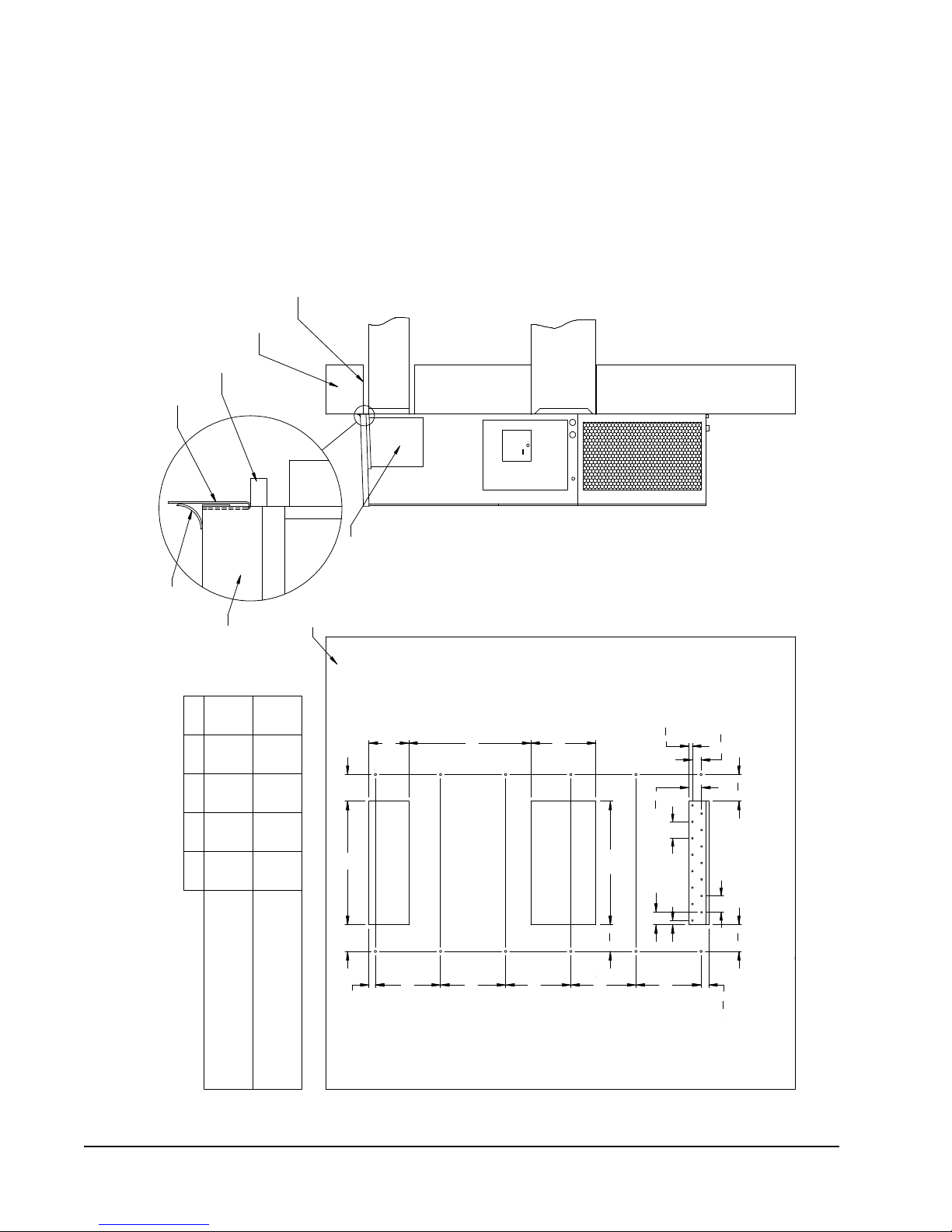
FIGURE 3C
Manual 2100-640F
Page 10 of 32
Mounting Instructions
W42AA, W42LA, W48AA, W48LA
Page 11

D
16"
16"
16"
16"
16"
2
"6
8
" 5
8 97
"
1"
3"
Typ.
1
4"
4"
Typ.
6
1
2
"
30"
E
16"
A CC
"
7
8
3
B
"
8
7
1
1
2
"6
1 1/430 1/2
1/4" CLEARANCE ON ALL
SUPPLIED
FOAM AIR SEAL
A
Supply Opening
SILICONE CAULKING BE PLACED BEHIND
DUCT
FOUR SIDES OF SUPPLY
FROM COMBUSTABLE
1/4" MIN. CLEARANCE FROM
COMBUSTIBLE MATERIALS
REQUIRED DIMENSIONS TO MAINTAIN
OPENING
COMBUSTIBLE MATERIALS
B D E
PANEL
AIR DUCT IS REQUIRED
32
10 1/2
Right Side View
SUPPLY AIR
RECOMMENDED 1" CLEARANCE FROM
MIS-3789
RAIN FLASHING
REQUIRED DIMENSIONS TO MAINTAIN
12
TOP.
MATERIALS
5 1/2
WALL STRUCTURE
2
6 1/4
29
29 3/4
IT IS RECOMMENDED THAT A BEAD OF
THE SIDE MOUNTING FLANGES AND UNDER
WALL
C
Wall Opening and Hole Location View
NOTES:
TOP FLASHING AT TIME OF INSTALLATION.
HEATER ACCESS
RETURN AIR
SEAL WITH BEAD
OF CAULKING ALONG
ENTIRE LENGTH OF
TOP
Return Opening
FIGURE 3D
Mounting Instructions
W60AA, W60LA, W72AB, W72LB
Manual 2100-640F
Page 11 of 32
Page 12
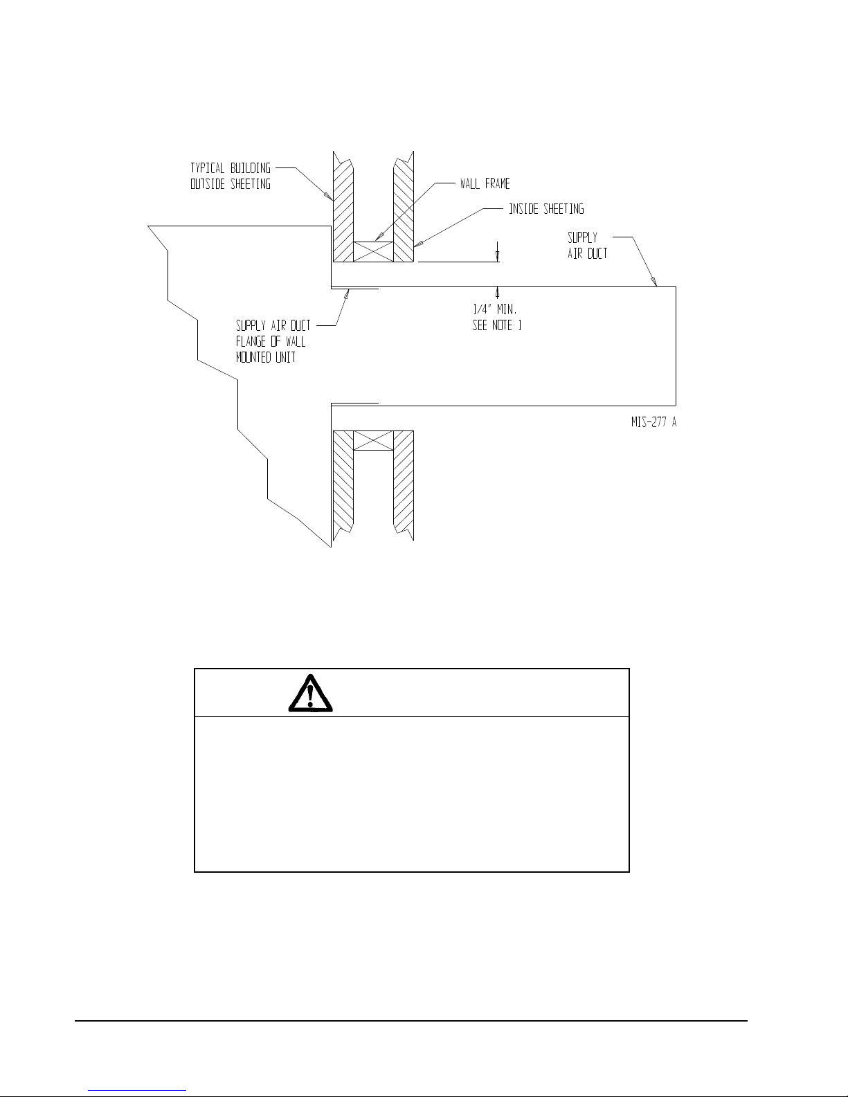
FIGURE 4
Electric Heat Clearance
W30AA, W30LA, W36AA, W36LA, W42AA, W42LA, W48AA, W48LA, W60AA, W60LA, W72AB, W72LB
NOTE 1: SIDE SECTION VIEW OF SUPPLY AIR
DUCT FOR WALL MOUNTED UNIT SHOWING 1/4"
CLEARANCE TO COMBUSTIBLE SURFACES.
WARNING
A minimum of 1/4" clearance must be maintained between the
supply air duct and combustible materials. This is required for the
rst 3' of ducting.
It is important to insure that the 1/4" minimum spacing is maintained
at all points.
Failure to do this could result in overheating the combustible
material and may result in a re causing damage, injury or death.
Manual 2100-640F
Page 12 of 32
Page 13
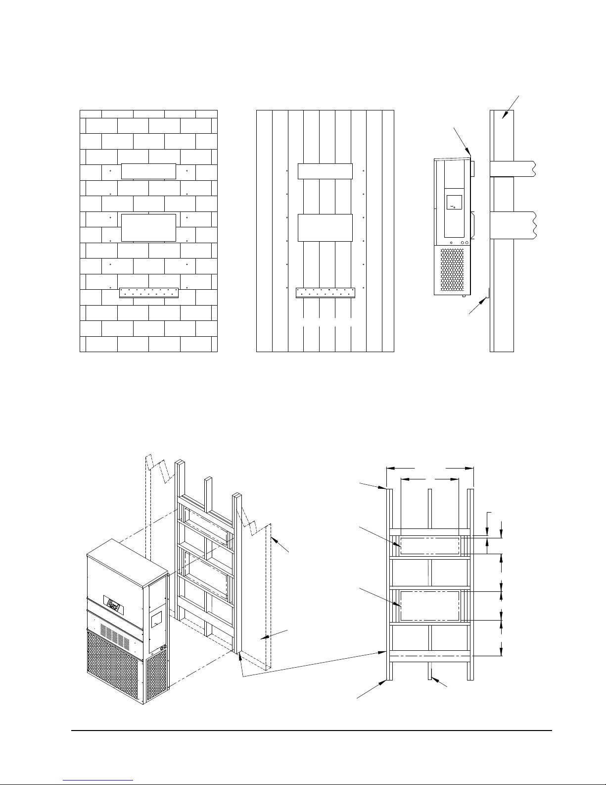
Wall Mounting Instructions
DUCT
OPENING
RETURN AIR
SUPPLY AIR
WOOD FRAME WALL INSTALLATION
OPENING
WALL BEFORE
MOUNT ON UNIT
OPENING
BEFORE INSTALLATION
BOTTOM MOUNTING
CONCRETE BLOCK WALL INSTALLATION
BRACKET. MOUNT ON
OPENING
WOOD OR STEEL SIDING
OPENING
INSTALLING UNIT.
RETURN AIR
WALL STRUCTURE
RETURN AIR
SUPPLY AIR
FACTORY SUPPLIED
RAIN FLASHING.
SUPPLY AIR
MIS-548 A
SIDE VIEW
I
A
C
K
E + 1.000
B
1.000
SUPPLY DUCT
OVER FRAME
INTERIOR FINISHED WALL
ALL AROUND DUCT
FRAMING MATERIAL
EXTERIOR FINISH WALL
OPENING
FOR ACTUAL DIMENSIONS.
2 x 4'S, 2 x 6'S &/OR
STRUCTURAL STEEL
ATTACH TO TOP
1.000" CLEARANCE
1.000" CLEARANCE
PLATE OF WALL
C
SEE UNIT DIMENSIONS, FIGURE 2,
OPENING
RETURN DUCT
2 x 6
ATTACH TO BOTTOM
OVER FRAME
PLATE OF WALL
L
THIS STRUCTURAL MEMBER
LOCATED TO MATCH STUD
SPACING FOR REST OF WALL.
A SECOND MEMBER MAY BE
REQUIRED FOR SOME WALLS.
MIS-549 B
ALL AROUND DUCT
SEE FIGURES 3A THROUGH 3D – MOUNTING INSTRUCTIONS
FIGURE 5
Wall Mounting Instructions
FIGURE 6
Manual 2100-640F
Page 13 of 32
Page 14

FIGURE 7
Common Wall Mounting Installations
SUPPLY DUCT MAY BE LOCATED IN AN ATTIC
OR BELOW CEILING RAFTERS AS SHOWN
RAIN
FLASHING
OUTSI DE
WALL
RAIN
FLASHING
RAFTERS
FINISHED CEILING SURFACE
SUPPLY AIR DUCT
W/ GRILLE
RETURN AI R
OPENI NG W/ GRI LLE
FREE AIR FLOW
NO DUCT
SUPPLY DUCT MAYBE LOCATED IN AN ATTIC
OR BELOW CEILING RAFTERS AS SHOWN
RAFTERS
RAIN
FLASHING
OUTSI DE
WALL
RAIN
FLASHING
RAFTERS
SUPPLY AIR DUCT
FINISHED CEILING SURFACE
RETURN AI R
OPENI NG W/ GRI LLE
DUCTED SUPPLY
RETURN AT UNIT
SUPPLY DUCT MAYBE LOCATED IN AN ATTIC
OR BELOW CEILING RAFTERS AS SHOWN
RAFTERS
OUTSI DE
WALL
FALSE WALL INSTALLATION
Manual 2100-640F
Page 14 of 32
SUPPLY AIR DUCT
FINISHED
CEILING SURFACE
WALL SLEEVE
FALSE WALL
RETURN AI R GRILLE
RETURN AI R
SPACE
OUTSI DE
WALL
SUPPLY AIR DUCT
LOWERED
CEILING
CLOSET WALL
WALL
SLEEVE
RAISED FLOOR
RETURN AI R
SUPPLY AIR
GRILLE
FINISHED CEILING
CLOSET INSTALLATION
SURFACE
RETURN AI R
GRILLE
MIS-550 C
Page 15
WIRING – MAIN POWER
Refer to the unit rating plate for wire sizing information
and maximum fuse or circuit breaker size. Each
outdoor unit is marked with a “Minimum Circuit
Ampacity”. This means that the field wiring used must
be sized to carry that amount of current. Depending
on the installed KW of electric heat, there may be
two field power circuits required. If this is the case,
the unit serial plate will so indicate. All models are
suitable only for connection with copper wire. Each
unit and/or wiring diagram will be marked “Use Copper
Conductors Only”. These instructions must be adhered
to. Refer to the National Electrical Code (NEC) for
complete current carrying capacity data on the various
insulation grades of wiring material. All wiring must
conform to NEC and all local codes.
The electrical data lists fuse and wire sizes (75° C
copper) for all models including the most commonly
used heater sizes. Also shown are the number of field
power circuits required for the various models with
heaters.
The unit rating plate lists a “Maximum Time Delay
Relay Fuse” or circuit breaker that is to be used with
the equipment. The correct size must be used for
proper circuit protection and also to assure that there
will be no nuisance tripping due to the momentary high
starting current of the compressor motor.
The disconnect access door on this unit may be locked
to prevent unauthorized access to the disconnect. To
convert for the locking capability, bend the tab located
in the bottom left-hand corner of the disconnect
opening under the disconnect access panel straight
out. This tab will now line up with the slot in the door.
When shut, a padlock may be placed through the hole
in the tab preventing entry.
See “Start Up” section for important information on
three phase scroll compressor start ups.
See Tables 7 and 8 on pages 26 and 27 for electrical
specifications.
WIRING – LOW VOLTAGE WIRING
All 230/208V 1 phase and 3 phase equipment have
dual primary voltage transformers. All equipment
leaves the factory wired on 240V tap. For 208V
operation, reconnect from 240V to 208V tap. The
acceptable operating voltage range for the 240 and
208V taps are:
TAP RANGE
240 253 – 216
208 220 – 187
For low voltage wiring, an 18 gauge copper, color-coded
cable is recommended. See Table 4 on page 16 for
more information.
Low Voltage Connections
These units use a 24-volt AC low voltage circuit.
The “RT” terminal is the 24V transformer output,
and the “R” terminal is the 24VAC hot terminal
for the operation of the equipment. “RT” and “R”
are connected with brass jumper bar which can be
removed and “RT” and “R” connected to external
NC (normally closed) contact such as a fire/smoke
detector that will cause immediate shutdown of the
equipment upon activation.
“C” terminal is grounded.
“G” terminal is the fan input.
“Y1” terminal is the 1st Stage input for cooling.
“Y2” terminal is the 2nd Stage compressor input for
cooling (if equipped with an economizer).
“B/W1” terminal is the 1st stage electric heat.
“W2” terminal is the 2nd stage heat (if equipped).
“A” terminal is the ventilation input. This terminal
energizes any factory-installed ventilation option and
indoor blower.
“D” terminal is the dehumidification input. If
installed, this terminal energizes any factory installed
dehumidification option.
For units equipped with an alarm relay:
"L/1" terminal is the normally closed contact on the
relay.
"2" terminal is the normally open contact on the relay.
"3" terminal is the common contact on the relay.
LOW VOLTAGE CONNECTIONS FOR DDC CONTROL
Standard Units
Fan Only Energize G Energize G
1st Stage
Cooling Mode
2nd Stage
Cooling Mode
1st Stage Heating Energize B/W1 Energize B/W1
2nd Stage Heating
(if employed)
Ventilation Energize A Energize A
Dehumidification
(if employed)
Energize Y1, G Energize Y1, G
Energize B/W1, W2 Energize B/W1, W2
Energize D Energize D
Units w/
Economizers
Energize Y1, Y2, G
NOTE: The voltage should be measured at the field
power connection point in the unit and while
the unit is operating at full load (maximum
amperage operating condition).
Manual 2100-640F
Page 15 of 32
Page 16
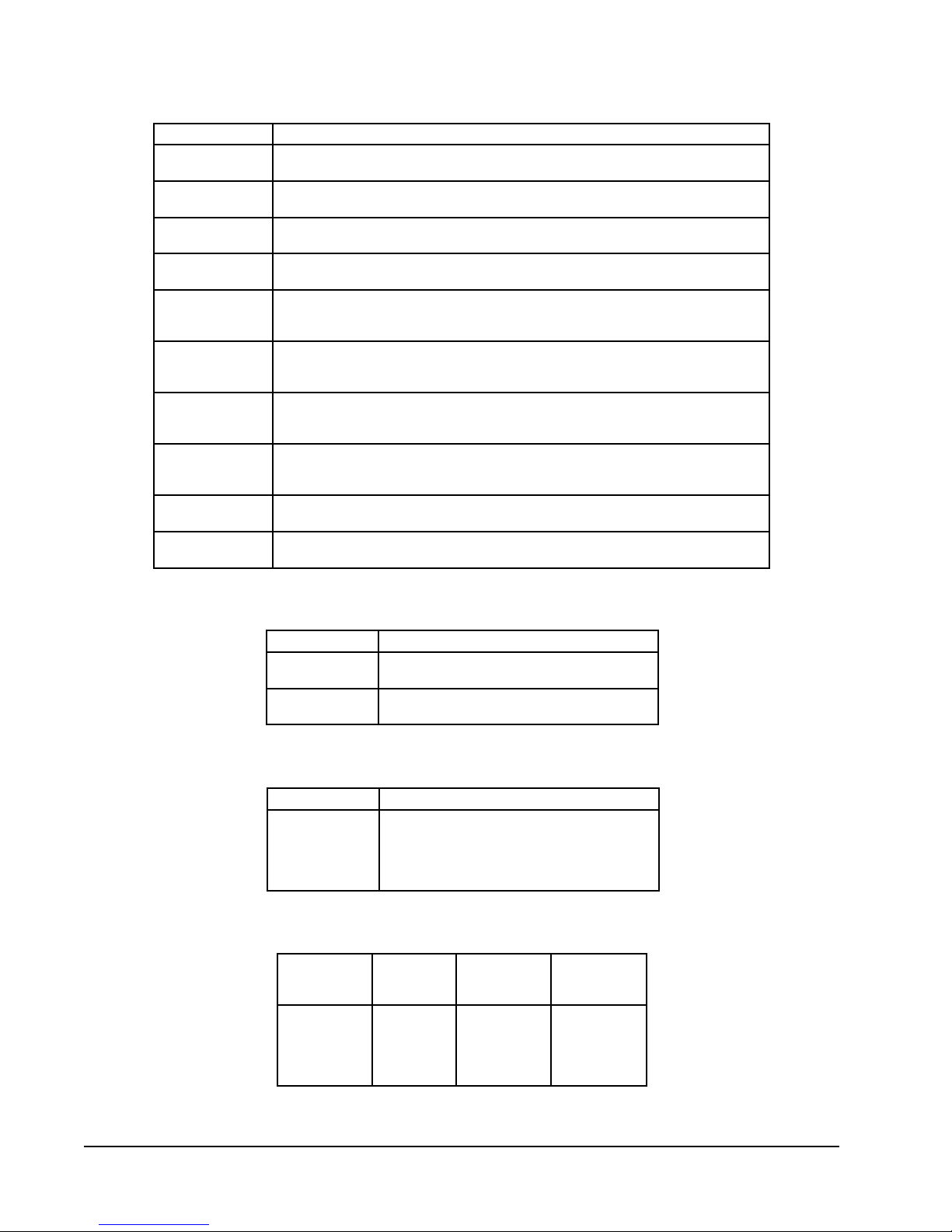
TABLE 1
Wall Thermostats
Part Number Predominate Features
8403-057
(TH3110D1040)
8403-058
(TH5220D1151)
8403-059
(TH5220D1219/U)
8403-060
(1120-445)
CS9B-THO
CS9B-THOC
CS9BE-THO
CS9BE-THOC
8403-089
(T4 Pro)
8403-090
(T6 Pro)
1 stage Cool, 1 stage Heat; Electronic Non-Programmable; Auto or Manual changeover
2 stage Cool, 2 stage Heat; Electronic Non-Programmable;
HP or Conventional (Default: HP); Auto or Manual changeover
2 stage Cool, 2 stage Heat; Electronic Non-Programmable;
HP or Conventional (Default: AC); Auto or Manual changeover
3 stage Cool; 3 stage Heat; Electronic Programmable/Non-Programmable;
HP or Conventional; Auto or Manual changeover; Dehumidification Output
3 stage Cool, 3 stage Heat; Programmable/
Auto or Manual Changeover; Humidity Sensor w/ dehumidification; Motion Sensor w/
Intelligent Learning Control; BACnet-compatible
3 stage Cool, 3 stage Heat; Programmable/
Auto or Manual Changeover; Humidity Sensor w/ dehumidification; CO2 Sensor; Motion
Sensor w/Intelligent Learning Control; BACnet-compatible
3 stage Cool, 3 stage Heat; Programmable/
Auto or Manual Changeover; Humidity Sensor w/ dehumidification; Motion Sensor w/
Intelligent Learning Control; BACnet-compatible; Ethernet-compatible
3 stage Cool, 3 stage Heat; Programmable/
or Manual Changeover; Humidity Sensor w/dehumidification; CO
w/Intelligent Learning Control; BACnet-compatible; Ethernet-compatible
1 stage Cool, 1 stage Heat – Heat Pump; 1 stage Cool, 1 stage Heat – Conventional
Programmable/Non-Programmable Electronic; Auto or Manual changeover
2 stage Cool, 3 stage Heat – Heat Pump; 2 stage Cool, 2 stage Heat – Conventional
Programmable/Non-Programmable Electronic; Auto or Manual changeover
Non-Programmable
Non-Programmable
Non-Programmable
Non-Programmable
; HP or
Conventional
; HP or
Conventional
; HP or
Conventional
; HP or
Conventional; Auto
Sensor; Motion Sensor
2
;
;
;
TABLE 2
Humidity Controls
Part Number Predominate Features
8403-038
(H600A1014)
8403-047
(H200-10-21-10)
SPDT switching, pilot duty 50VA @ 24V
Humidity range 20-80% RH
Electronic dehumidstat SPST closes-on-rise
Humidity range 10-90% with adjustable stops
TABLE 3
CO2 Controller
Part Number Predominate Features
Normally Open SPST relay closes-on-rise
8403-067
24V dual wave length sensor. Default setting
950ppm, adjustable to 0-2000ppm
Default off setting 1000ppm, adjustable to
0-200 ppm can be calibrated
TABLE 4
Thermostat Wire Size
Transformer
VA
55 2.3
FLA Wire Gauge
20 gauge
18 gauge
16 gauge
14 gauge
12 gauge
Maximum
Distance
In Feet
45
60
100
160
250
Manual 2100-640F
Page 16 of 32
Page 17
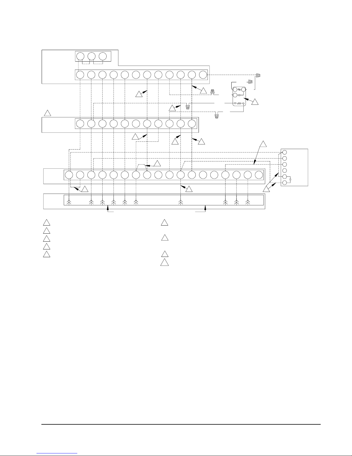
FIGURE 8
Programmable Thermostat Connections
Completestat
Model #CS9B-THO or
Model #CS9BE-THO
7
Thermostat
Bard #8403-060
Unit Low
Voltage
Term. Strip
Vent Plug
Factory installed jumper. Remove jumper and connect
1
to N.C fire alarm circuit if emergency shutdown required.
Wire not needed below 15KW.2
Wire required for dehumidification models only.
3
Do not connect "A" from thermostat if optional CO2 controller is used
4
Relay Provided with Completestat5
SCSCSC
24V
COM
1
G
Y1 Y2 O/B L DA GND
2
B/W1
6 1012119 412-Pin
23 5 7
If not equipped with a ventilation option to plug in, a jumper plug must be installed.
ALL VENT OPTIONS PLUG IN HERE
W1/E
W2
Yellow
3
2
4
W1/E
LO/BY2Y1R GC W2
8
W3/8 76532R
W2C GRT Y1 Y2
L/1 DA 4
0-10 VDC modulating C02 control signal for modulating ventilation control (optional for
6
ECON only - see vent instruction manuals)
Change model configuration from heat pump to heat/cool. Must be configured to programmable
and fan set to be programmed fan for the "A" output to function during scheduled occupied
7
periods. Must be configured for multi-stage for Y1 output to be active 1st stage cooling. For
dehumidification, must be configured for "No Economizer" for YO/D to be active for humidity
control.
Install jumper for 1 stage electric heat on units with less than 15KW
8
Do not add these wires if setting up for modulating control. See note 7.
9
YO/D
A
4
3
4
Orange
White
Red
Blue
5
Optional CO2 Controller
6
Bard Part #8403-067
1
24VAC
2
CO2 OUT
3
4
TEMP-OUT
5
6
9
MIS-3738 A
Manual 2100-640F
Page 17 of 32
Page 18
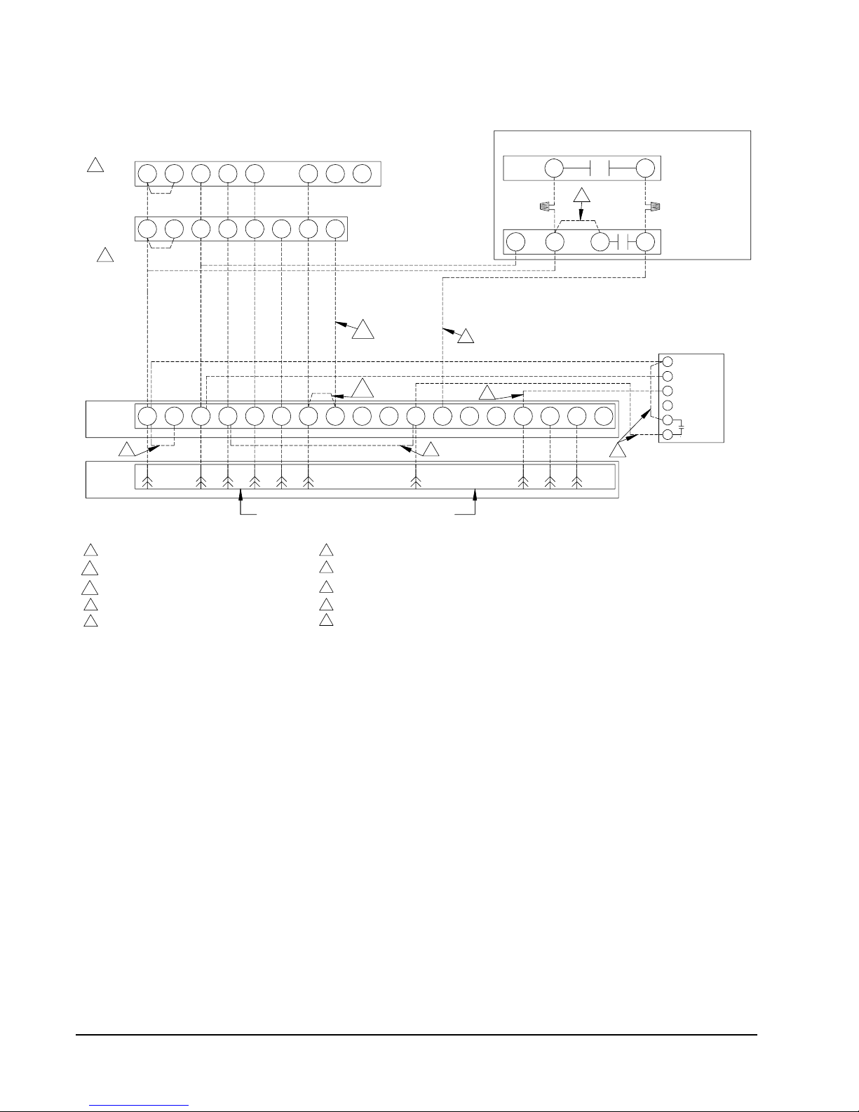
9
8403-057
(TH311OD1040)
or T4 Pro 8403-089
8403-058
(TH522OD1151)
8403-059
(TH522OD1219/U)
or T6 Pro 8403-090
7
FIGURE 9
Thermostat Connections
Units With Dehumidification
8403-038
G
WCRc YR
O B
8
WRc CR G Y Y2 W2
6
35
Mechanical Humidistat
8403-047
4
Electronic Humidistat
Unit Low
Voltage
Term. Strip
1
Vent Plug
23 56 7
ALL VENT OPTIONS PLUG IN HERE
If not equipped with a ventilation option to plug in, a jumper plug must be installed.
Factory installed jumper. Remove jumper and connect
1
to N.C fire alarm circuit if emergency shutdown required.
Wire not needed below 15KW.
2A
Install Jumper for 1 stage electric heat on units with more
2B
than 10KW.
Wire required for dehumidification models only.
3
For vent operation, add jumper if optional CO2 controller is not used.
4
Vent will run while blower is energized.
B/W1
2A
2B
W3/8
W2C GRT Y1 Y2
L/1 DA
3
6
4
4
5 Do not add these wires if setting up for modulating control. See note 7.
0-10 VDC Modulating CO2 control signal for modulating ventilation control
6
(Optional for ECON Only) - See vent installation manual.
For 8403-058, change "system type", set up Function 1, From 5 (2 Heat/ 1 Cool heat Pump)
7
to 6 (2 Heat / 2 Cool Conventional). For 8403-059, No change required.
8
Jumper needs added.
9
Thermostat will not work with units equipped with economizers.
Optional CO2 Controller
Bard Part #8403-067
1
24VAC
2
CO2 OUT
3
TEMP-OUT
76532R
4
5
6
5
1012119 412-Pin
MIS-3739 C
Manual 2100-640F
Page 18 of 32
Page 19
START UP
THESE UNITS REQUIRE R-410A
REFRIGERANT AND POLYOL ESTER OIL.
GENERAL
1. Use separate service equipment to avoid cross
contamination of oil and refrigerants.
2. Use recovery equipment rated for R-410A
refrigerant.
3. Use manifold gauges rated for R-410A (800
psi/250 psi low).
4. R-410A is a binary blend of HFC-32 and HFC-
125.
5. R-410A is nearly azeotropic—similar to R-22 and
R-12. Although nearly azeotropic, charge with
liquid refrigerant.
6. R-410A operates at 40-70% higher pressure
than R-22 and systems designed for R-22 cannot
withstand this higher pressure.
7. R-410A has an ozone depletion potential of zero,
but must be reclaimed due to its global warming
potential.
8. R-410A compressors use Polyol Ester oil.
9. Polyol Ester oil is hygroscopic; it will rapidly absorb
moisture and strongly hold this moisture in the oil.
10. A liquid line dryer must be used—even a deep
vacuum will not separate moisture from the oil.
11. Limit atmospheric exposure to 15 minutes.
REMEMBER: When adding R-410A refrigerant, it must
come out of the charging cylinder/tank as a liquid to
avoid any fractionation, and to ensure optimal system
performance. Refer to instructions for the cylinder that
is being utilized for proper method of liquid extraction.
WARNING
Failure to conform to these practices
could lead to damage, injury or death.
SAFETY PRACTICES
1. Never mix R-410A with other refrigerants.
2. Use gloves and safety glasses. Polyol Ester oils
can be irritating to the skin, and liquid refrigerant
will freeze the skin.
3. Never use air and R-410A to leak check; the
mixture may become flammable.
4. Do not inhale R-410A—the vapor attacks
the nervous system, creating dizziness, loss
of coordination and slurred speech. Cardiac
irregularities, unconsciousness and ultimate death
can result from breathing this concentration.
5. Do not burn R-410A. This decomposition
produces hazardous vapors. Evacuate the area if
exposed.
12. If compressor removal is necessary, always plug
compressor immediately after removal. Purge with
small amount of nitrogen when inserting plugs.
TOPPING OFF SYSTEM CHARGE
If a leak has occurred in the system, Bard
Manufacturing recommends reclaiming, evacuating
(see criteria above) and charging to the nameplate
charge. If done correctly, topping off the system
charge can be done without problems.
With R-410A, there are no significant changes in the
refrigerant composition during multiple leaks and
recharges. R-410A refrigerant is close to being an
azeotropic blend (it behaves like a pure compound
or single component refrigerant). The remaining
refrigerant charge, in the system, may be used after
leaks have occurred and then “top-off” the charge by
utilizing the pressure charts on the inner control panel
cover as a guideline.
6. Use only cylinders rated DOT4BA/4BW 400.
7. Never fill cylinders over 80% of total capacity.
8. Store cylinders in a cool area, out of direct
sunlight.
9. Never heat cylinders above 125°F.
10. Never trap liquid R-410A in manifold sets, gauge
lines or cylinders. R-410A expands significantly
at warmer temperatures. Once a cylinder or line is
full of liquid, any further rise in temperature will
cause it to burst.
IMPORTANT INSTALLER NOTE
For improved start up performance, wash the indoor
coil with a dishwashing detergent.
Manual 2100-640F
Page 19 of 32
Page 20

HIGH PRESSURE SWITCH
All W**A/W**L wall mounted air conditioner series
models are supplied with a remote reset for the high
and low pressure switch. If tripped, this pressure
switch may be reset by turning the thermostat off then
back on again.
THREE PHASE SCROLL COMPRESSOR
START UP INFORMATION
Scroll compressors, like several other types of
compressors, will only compress in one rotational
direction. Direction of rotation is not an issue with
single phase compressors since they will always start
and run in the proper direction.
However, three phase compressors will rotate in either
direction depending upon phasing of the power.
Since there is a 50-50 chance of connecting power
in such a way as to cause rotation in the reverse
direction, verification of proper rotation must be made.
Verification of proper rotation direction is made by
observing that suction pressure drops and discharge
pressure rises when the compressor is energized.
Reverse rotation also results in an elevated sound level
over that with correct rotation, as well as substantially
reduced current draw compared to tabulated values.
Verification of proper rotation must be made at the time
the equipment is put into service. If improper rotation
is corrected at this time, there will be no negative
impact on the durability of the compressor. However,
reverse operation for over 1 hour may have a negative
impact on the bearing due to oil pump out.
NOTE: If compressor is allowed to run in reverse
rotation for an extended period of time, the
compressor’s internal protector will trip.
All three phase compressors are wired identically
internally. As a result, once the correct phasing
is determined for a specific system or installation,
connecting properly phased power leads to the same
Fusite terminal should maintain proper rotation
direction.
The direction of rotation of the compressor may be
changed by reversing any two line connections to the
unit.
PHASE MONITOR
All units with three phase scroll compressors are
equipped with a three phase line monitor to prevent
compressor damage due to phase reversal.
The phase monitor in this unit is equipped with two
LEDs. If the Y signal is present at the phase monitor
and phases are correct, the green LED will light.
If phases are reversed, the red fault LED will be lit and
compressor operation is inhibited.
If a fault condition occurs, reverse two of the supply
leads to the unit. Do not reverse any of the unit factory
wires as damage may occur.
CONDENSER FAN OPERATION
NOTE: Certain models may be equipped with a
low ambient control (LAC), and if so, the
condenser fan motor will have a delayed start
until system refrigerant operating pressure
builds up. After starting, the fan motor may
or may not cycle depending upon ambient
conditions. This is normal operation.
The condenser fan motor on 230/208 volt, one
and three phase, 60 HZ units is a two-speed motor
that comes factory wired on high speed for peak
performance. If ambient conditions permit, it can be
reconnected to low speed (red wire) for lower sound
level. See wiring diagram. (This applies to W42, W48,
W60 and W72 models only.)
50 HZ models must have fan wired on low speed.
These models are factory wired on low speed.
SERVICE HINTS
1. Caution owner/operator to maintain clean air
filters at all times and also not to needlessly close
off supply and return air registers. This reduces
airflow through the system, which shortens
equipment service life as well as increasing
operating costs.
2. Check all power fuses or circuit breakers to be sure
they are the correct rating.
3. Periodic cleaning of the outdoor coil to permit full
and unrestricted airflow circulation is essential
.
SEQUENCE OF OPERATION
COOLING – Circuit R-Y1 makes at thermostat pulling
in compressor contactor, starting the compressor and
outdoor motor. (See NOTE above under Condenser
Fan Operation concerning models equipped with low
ambient control.) The G (indoor motor) circuit is
automatically completed by the thermostat on any call
for cooling operation or can be energized by manual
fan switch on subbase for constant air circulation.
On a call for heating, circuit R-W1 makes at the
thermostat pulling in heat contactor for the strip heat
and blower operation. On a call for second stage heat,
R-W2 makes bringing on second heat contactor, if so
equipped.
VENT CONNECTION PLUG
All units are equipped with a vent connection plug in
the side of the control panel for the different ventilation
packages to plug in to. If the compressor will not start
and there is no "Y1" at the compressor control module,
Manual 2100-640F
Page 20 of 32
Page 21

first check to make sure that either the optional vent is
plugged into the vent connection plug or the supplied
jumper plug is in place. The unit will not operate
without anything plugged in. This plug is located on
the side of the control panel behind the front vent door
(behind the filter access door). If the unit is supplied
with a factory-installed vent package, it will be plugged
in but the jumper plug will also be tethered next to the
connection for troubleshooting purposes, if necessary.
COMPRESSOR CONTROL MODULE
The compressor control module is standard on all
models covered by this manual. The compressor
control module is an anti-short cycle/lockout timer with
high and low pressure switch monitoring and alarm
relay output.
Alarm Relay Output
Alarm terminal is output connection for applications
where alarm relay is employed. This terminal is
powered whenever the compressor is locked out due to
HPC or LPC sequences as described.
NOTE: Both high and low pressure switch controls are
inherently automatic reset devices. The high
pressure switch and low pressure switch cut
out and cut in settings are fixed by specific air
conditioner unit model. The lockout features,
both soft and manual, are a function of the
compressor control module.
Adjustments
Adjustable Delay-on-Make and Delay-on-Break Timer
Adjustable Delay-on-Make and Delay-on-Break Timer
On initial power up or anytime power is interrupted to
the unit, the delay-on-make period begins, which will
be 2 minutes plus 10% of the delay-on-break setting.
When the delay-on-make is complete and the high
pressure switch and low pressure switch are closed, the
compressor contactor is energized. Upon shutdown,
the delay-on-break timer starts and prevents restart
until the delay-on-break and delay-on-make periods
have expired.
During routine operation of the unit with no power
interruptions, the compressor will operate on demand
with no delay.
High Pressure Switch and Lockout Sequence
If the high pressure switch opens, the compressor
contactor will de-energize immediately. The lockout
timer will go into a soft lockout and stay in soft lockout
until the high pressure switch closes and the delayon-break time has expired. If the high pressure switch
opens again in this same operating cycle, the unit will
go into manual lockout condition and the alarm relay
circuit will energize. Recycling the wall thermostat
resets the manual lockout.
Low Pressure Switch, Bypass and Lockout Sequence
If the low pressure switch opens for more than 120
seconds, the compressor contactor will de-energize and
go into a soft lockout. Regardless the state of the low
pressure switch, the contactor will re-energize after
the delay-on-make time delay has expired. If the low
pressure switch remains open, or opens again for longer
than 120 seconds, the unit will go into manual lockout
condition and the alarm relay circuit will energize.
Recycling the wall thermostat resets the manual lockout.
The potentiometer is used to select delay-on-break time
from 30 seconds to 5 minutes. Delay-on-make (DOM)
timing on power up and after power interruptions is equal
to 2 minutes plus 10% of delay-on-break (DOB) setting:
0.5 minute (30 seconds) DOB = 123 second DOM
1.0 minute (60 seconds) DOB = 126 second DOM
2.0 minute (120 seconds) DOB = 132 second DOM
3.0 minute (180 seconds) DOB = 138 second DOM
4.0 minute (240 seconds) DOB = 144 second DOM
5.0 minute (300 seconds) DOB = 150 second DOM
During routine operation of the unit with no power
interruptions, the compressor will operate on demand
with no delay.
Typical Settings for Dual Unit Installation:
Unit 1: DOB set at 2 minutes and DOM is 132 seconds
Unit 2: DOB set at 4 minutes and DOM is 144 seconds
PRESSURE SERVICE PORTS
High and low pressure service ports are installed on
all units so that the system operating pressures can
be observed. A pressure table covering all models can
be found on page 25. It is imperative to match the
correct pressure table to the unit by model number.
This unit employs high-flow Coremax valves instead of
the typical Shrader type valves.
WARNING! Do NOT use a Schrader valve core removal
tool with these valves. Use of such a tool could result
in eye injuries or refrigerant burns!
To change a Coremax valve without first removing the
refrigerant, a special tool is required which can be
obtained at www.fastestinc.com/en/SCCA07H. See the
replacement parts manual for replacement core part
numbers.
Manual 2100-640F
Page 21 of 32
Page 22
SERVICE
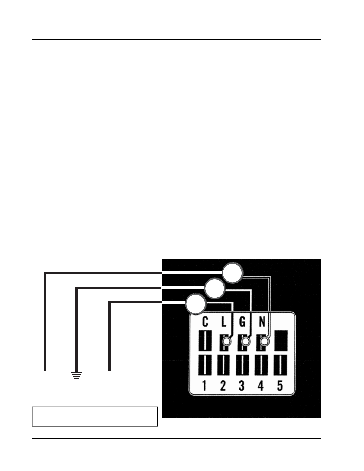
FIGURE 10
NOTE: Bard Models PA13242; PA13302; PA13362-A, -B; PA13422-A, -B, -C; PA13482-A, -B, -C; PA13602-A, -B, -C
contain the X13-Series Motors.
TROUBLESHOOTING GE X13-SERIES ECM2.3™ MOTORS
If the Motor is Running
1. It is normal for the motor to rock back and forth on start up.
Do not replace the motor if this is the only problem identified.
2. If the system is excessively noisy, does not appear to change
speeds in response to a demand (Heat, Cool, Other), or is having
symptoms during the cycle such as tripping limit or freezing coil,
check the following:
a. Wait for programmed delays to time out.
b.Ensure that the motors control inputs are wired to the factory
supplied wiring diagram to insure motor is getting proper
control signals and sequencing.
c. Remove the filter and check that all dampers, registers, and
grilles are open and free flowing. If removing the filters
corrects the problem, clean or replace with a less restrictive
filter. Also check and clean the blower wheel or coil as
necessary.
d.Check the external static pressure (total of both supply and
return) to insure that you are within the ranges as listed on the
unit serial plate. If higher than allowed, additional duct work
is needed.
e. If the motor does not shut off at the end of the cycle, wait for
any programmed delays to time out (no more than 90
seconds). Also make sure that there is no call for
“Continuous Fan” on the "G" terminal.
f. If the above diagnostics do not solve the problem, confirm the
voltage checks in the next section below, then continue with
the “Model X13 Communication Diagnostics”.
If the Motor is Not Running
1. Check for proper high voltage and ground at the (L/L1) (G) (N/
L2) connections at the motor (see Figure 10). Correct any voltage
issues before proceeding to the next step. The X13 Motor is voltage
specific. Only the correct voltage should be applied to the proper
motor. Input voltage within plus or minus 10% of the nominal 230
VAC is acceptable.
2. If the motor has proper high voltage and ground at the (L/L1)
(G) (N/L2) connections, then continue with the “Model X13
Communication Diagnostics”.
TROUBLESHOOTING NIDEC
SELECTECH SERIES ECM MOTORS
D. Check the external static pressure (total of
both supply and return) to ensure it is within
the range as listed on the unit serial plate. If
If the Motor Is Running
1. It is normal for the motor to rock back and forth
on start up. Do not replace the motor if this is the
E. If the motor does not shut off at the end of the
only problem identified.
2. If the system is excessively noisy, does not appear
to change speeds in response to a demand (Heat,
Cool, Other) or is having symptoms during the
cycle such as tripping limit or freezing coil, check
the following:
A. Wait for programmed delays to time out.
B. Ensure that the motors control inputs are
wired as shown in the factory-supplied wiring
diagram to ensure motor is getting proper
control signals and sequencing.
C. Remove the filter and check that all dampers,
registers and grilles are open and free flowing.
If removing the filters corrects the problem,
clean or replace with a less restrictive filter.
Also check and clean the blower wheel or coil
as necessary.
FIGURE 10
Motor Connections
F. If the above diagnostics do not solve the
If the Motor Is Not Running
1. Check for proper high voltage and ground at the
higher than allowed, additional duct work is
needed.
cycle, wait for any programmed delays to time
out (no more than 90 seconds). Also make
sure that there is no call for “Continuous Fan”
on the “G” terminal.
problem, confirm the voltage checks in
the next section below, then continue with
the “Model SelecTech Communication
Diagnostics”.
(L/L1) (G) (N/L2) connections at the motor (see
Figure 10). Correct any voltage issues before
proceeding to the next step. The SelecTech motor
is voltage specific. Only the correct voltage should
be applied to the proper motor. Input voltage
within plus or minus 10% of the nominal Line
Power VAC is acceptable.
↓
L2 LINE
POWER
EARTH
GROUND
↓
L1 LINE
POWER
NOTE: MOTOR IS CONS TANTLY
POWERED BY LINE VOLTAGE
LINE
POWER
GROUND
LINE
POWER
Manual 2100-640F
Page 22 of 32
Page 23

FIGURE 11
™
MOTORS
CONT’D.
2. Initiate a demand from the thermostat and check the
voltage between the common and the appropriate motor
terminal (1-5). ("G" input is typically on terminal #1, but
refer to wiring diagram!)
a. If the low voltage communication is not present, check
the demand from the thermostat. Also check the
output terminal and wire(s) from the terminal strip or
control relay(s) to the motor.
b. If the motor has proper high voltage as identified
above (Motor not Running #1), and proper low voltage
to a programmed terminal, and is not operating, the
motor is failed, and will require replacement.
2. If the motor has proper high voltage and ground at
the (L/L1) (G) (N/L2) connections, then continue
with the “Model SelecTech Communication
Diagnostics”.
Model SelecTech Communication Diagnostics
The SelecTech motor is communicated through 24 VAC
low voltage (Thermostat Control Circuit Wiring).
1. Start with unit wiring diagram to confirm proper
connections and voltage (see Figure 11).
2. Initiate a demand from the thermostat and
check the voltage between the common and the
appropriate motor terminal (1-5). (“G” input is
typically on terminal #1, but always refer to wiring
diagram.)
FIGURE 11
Motor Connections
A. If the low voltage communication is not
present, check the demand from the
thermostat. Also check the output terminal
and wire(s) from the terminal strip or control
relay(s) to the motor.
B. If the motor has proper high voltage as
identified above (Motor not Running #1),
proper low voltage to a programmed terminal
and is not operating, the motor is failed and
will require replacement.
24VAC Co mmon
24VAC "R" Sig nal through
thermostat output.
24VAC Co mmon
24VAC "R" Sig nal through
thermostat outp ut.
Manual 2100-640F
Page 23 of 32
Page 24
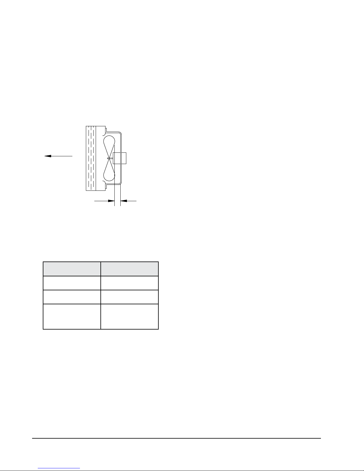
FAN BLADE SETTING DIMENSIONS
R-410A REFRIGERANT CHARGE
Shown in Figure 12 is the correct fan blade setting for
proper air delivery across the outdoor coil. Refer to
Table 5 for unit specific dimension.
Any service work requiring removal or adjustment in the
fan and/or motor area will require that the dimensions
below be checked and blade adjusted in or out on the
motor shaft accordingly.
FIGURE 12
Fan Blade Setting
AIRFLOW
"A"
MIS-1724
This unit was charged at the factory with the quantity
of refrigerant listed on the serial plate. AHRI capacity
and efficiency ratings were determined by testing with
this refrigerant charge quantity.
The following pressure table shows nominal
pressures for the units. Since many installation
specific situations can affect the pressure readings,
this information should only be used by certified
technicians as a guide for evaluating proper system
performance. They shall not be used to adjust charge.
If charge is in doubt, reclaim, evacuate and recharge
the unit to the serial plate charge
.
REMOVAL OF FAN SHROUD
1. Disconnect all power to the unit.
2. Remove the screws holding both grilles, one on
each side of unit, and remove grilles.
3. Remove nine screws holding fan shroud to
condenser and bottom.
4. Unwire condenser fan motor.
5. Slide complete motor, fan blade and shroud
assembly out the left side of the unit.
6. Service motor/fan as needed.
Fan Blade Dimension
Model
W18AA/W18LA
W24AA/W24LA
W30AA/W30LA
W36AA/W36LA
W42AA/W42LA
W48AA/W48LA
W60AA/W60LA
W72AB/W72LB
7. Reverse steps to reinstall.
TABLE 5
Dimension
A
1.00"
1.25"
1.75"
Manual 2100-640F
Page 24 of 32
Page 25
TABLE 6
Cooling Pressure
Air Temperature Entering Outdoor Coil °F
Model
W18A/L
W24A/L
W30A/L
W36A/L
W42A/L
W48A/L
W60A/L
W72A/L
Low side pressure ± 4 PSIG
High side pressure ± 10 PSIG
Tables are based upon rated CFM (airflow) across the evaporator coil. If there is any doubt as to correct operating
charge being in the system, the charge should be removed and system evacuated and recharged to serial plate
charge weight.
NOTE: Pressure table based on high speed condenser fan operation. If condensing pressures appear elevated
Return Air Temp
(DB/WB)
75/62
80/67
85/72
75/62
80/67
85/72
75/62
80/67
85/72
75/62
80/67
85/72
75/62
80/67
85/72
75/62
80/67
85/72
75/62
80/67
85/72
75/62
80/67
85/72
Pressure 75 80 85 90 95 100 105 110 115 120 125
Low Side
High Side
Low Side
High Side
Low Side
High Side
Low Side
High Side
Low Side
High Side
Low Side
High Side
Low Side
High Side
Low Side
High Side
Low Side
High Side
Low Side
High Side
Low Side
High Side
Low Side
High Side
Low Side
High Side
Low Side
High Side
Low Side
High Side
Low Side
High Side
Low Side
High Side
Low Side
High Side
Low Side
High Side
Low Side
High Side
Low Side
High Side
Low Side
High Side
Low Side
High Side
Low Side
High Side
121
293
129
300
134
311
123
314
132
322
137
333
118
312
126
320
130
331
117
323
125
331
129
343
123
323
132
331
137
343
120
330
128
338
132
350
127
344
136
353
141
365
117
332
125
340
129
352
123
312
132
320
137
331
124
334
133
343
138
355
120
333
128
342
132
354
120
346
128
355
132
367
125
346
134
355
139
367
122
353
131
362
136
375
129
362
138
371
143
384
119
353
127
362
131
375
126
332
135
340
140
352
126
355
135
364
140
377
122
355
131
364
136
377
122
370
130
379
135
392
128
371
137
380
142
393
125
377
134
387
139
401
131
380
140
390
145
404
121
376
129
386
134
400
128
353
137
362
142
375
128
377
137
387
142
401
124
378
133
388
138
402
124
394
133
404
138
418
130
395
139
405
144
419
127
402
136
412
141
426
134
401
143
411
148
425
122
402
131
412
136
426
check condenser fan wiring. See “Condenser Fan Operation”.
131
376
140
386
145
400
129
401
138
411
143
425
126
403
135
413
140
427
127
419
136
430
141
445
132
421
141
432
146
447
130
428
139
439
144
454
136
421
145
432
150
447
124
427
133
438
138
453
134
400
143
410
148
424
131
425
140
436
145
451
128
428
137
439
142
454
129
446
138
457
143
473
135
447
144
458
149
474
132
454
141
466
146
482
137
444
147
455
152
471
126
454
135
466
140
482
136
425
145
436
150
451
133
451
142
463
147
479
131
454
140
466
145
482
131
473
140
485
145
502
137
474
146
486
151
503
134
482
143
494
148
511
140
467
150
479
155
496
128
483
137
495
142
512
137
452
147
464
152
480
135
479
144
491
149
508
133
483
142
495
147
512
134
500
143
513
148
531
138
501
148
514
153
532
136
510
145
523
150
541
142
492
152
505
157
523
130
512
139
525
144
543
140
480
150
492
155
509
137
507
146
520
151
538
135
511
144
524
149
542
136
528
145
542
150
561
140
528
150
542
155
561
137
540
147
554
152
573
145
518
155
531
160
550
132
542
141
556
146
575
142
510
152
523
157
541
139
536
149
550
154
569
137
540
146
554
151
573
137
558
147
572
152
592
142
558
152
572
157
592
139
570
149
585
154
605
148
545
158
559
164
579
134
574
143
589
148
610
144
540
154
554
159
573
141
567
151
582
156
602
138
570
148
585
153
605
138
587
148
602
153
623
144
587
154
602
159
623
141
601
151
616
156
638
151
573
161
588
167
609
136
607
145
623
150
645
Manual 2100-640F
Page 25 of 32
Page 26

TABLE 7
Electrical Specifications – W**AA Series
Rated
No. Field
MODEL
W18AA-A00, A0Z
W24AA-A00, A0Z
W24AA-B00, B0Z
W24AA-C00, C0Z
W30AA-A00*, A0Z*
W30AA-B00*, B0Z*
W30AA-C00*, C0Z*
W36AA-A00*, A0Z*
W36AA-B00*, B0Z*
W36AA-C00*, C0Z*
W42AA-A00, A0Z
W42AA-B00, B0Z
W42AA-C00, C0Z
W48AA-A00, A0Z
W48AA-B00, B0Z
W48AA-C00, C0Z
W60AA-A00, A0Z
W60AA-B00, B0Z
W60AA-C00, C0Z
W72AB-A00, A0Z
W72AB-B00, B0Z
W72AB-C00, C0Z
Maximum size of the time delay fuse or circuit breaker for protection of field wiring conductors.
Based on 75°C copper wire. All wiring must conform to the National Electrical Code and all local codes.
These “Minimum Circuit Ampacity” values are to be used for sizing the field power conductors. Refer to the National Electrical code (latest version), Article 310 for power conductor sizing.
* Top outlet supply option is available only factory installed and only on the selected models.
CAUTION: When more than one field power circuit is run through one conduit, the conductors must be derated. Pay special attention to Note 8 of Table 310 regarding Ampacity
IMPORTANT: While this electrical data is presented as a guide, it is important to electrically connect properly sized fuses and conductor wires in accordance with the National Electrical Code and all
Volts
Power
Circuits
1
1
1
1
1
1
1
1
1
1
1
1
1
1
1
1
1
1 or 2
1
1
1
1
1
1
1
1
1
1
1
1
1
1 or 2
1
1
1
1
1
1
1
1
1
1
1
1
1 or 2
1 or 2
1
1
1
1
1
1
1
1
1
1 or 2
1 or 2
1
1
1
1
1
1
1
1
1
1 or 2
1 or 2
1
1
1
1
2
1
1
1
1
1
1 or 2
1 or 2
1 or 3
1
1
1
1
2
1
1
1
Minimum
Circuit
Ampacity
A05
A08
A10
A04
A05
A08
A10
B06
C06
A05*
A08
A10*
A15
B06
B09*
B15
C06
C09*
C12
C15
A05*
A08
A10*
A15
B06*
B09*
B15
C06*
C09*
C12
C15
A05
A10
A15
A20
B06
B09
B15
B18
C09
C15
A05
A10
A15
A20
B06
B09
B15
B18
C09
C15
A05
A10
A15
A20
B06
B09
B15
B18
C09
C15
A05
A10
A15
A20
B06
B09
B15
B18
C09
C15
&
Phase
230/208-1
230/208-1
230/208-3
460-3
230/208-1
230/208-3
460-3
230/208-1
230/208-3
460-3
230/208-1
230/208-3
460-311
230/208-1
230/208-3
460-311
230/208-1
230/208-3
460-3
230/208-1
230/208-3
460-3
Adjustment Factors when more than three current carrying conductors are in a raceway.
local codes.
Single Circuit Multiple Circuit
110
110
112
N/A
114
N/A
16
30
46
56
21
25
30
46
56
15
22
9
11
26
32
47
58
84
19
24
33
51
9
12
17
21
26
29
32
47
58
84
23
24
33
51
11
12
17
21
26
32
32
58
84
25
25
33
51
60
12
17
26
34
34
58
84
26
26
33
51
60
12
17
26
38
38
60
86
27
27
35
53
14
18
27
58
58
62
88
40
40
40
55
18
18
27
Maximum
External
Fuse or
Ckt. Brkr.
20
30
50
60
30
30
30
50
60
20
25
15
15
35
35
50
60
90
20
25
35
60
15
15
20
25
30
35
35
50
60
90
30
30
35
60
15
15
20
25
30
50
50
60
90
125
35
35
35
60
60
15
20
30
50
50
60
90
125
35
35
35
60
60
15
20
30
60
60
60
90
125
40
40
40
60
N/A
20
20
30
60
60
70
90
125
60
60
60
60
N/A
25
25
30
Field
Power
Wire
Size
12
10
8
6
10
10
10
8
6
12
10
14
14
8
8
8
6
4
12
10
8
6
14
14
12
10
10
8
8
8
6
4
10
10
8
6
14
14
12
10
10
8
8
6
4
2
8
8
8
6
6
14
12
10
8
8
6
4
2
8
8
8
6
6
14
12
10
8
8
6
3
2
8
8
8
6
N/A
12
12
10
6
6
6
3
2
8
8
8
6
N/A
10
10
10
Ground
Wire
12
10
10
10
10
10
10
10
10
12
10
14
14
10
10
10
10
12
10
10
10
14
14
12
10
10
10
10
10
10
10
10
10
10
14
14
12
10
10
10
10
10
10
10
10
10
10
14
12
10
10
10
10
10
10
10
10
10
14
12
10
10
10
10
10
10
10
10
N/A 35 28 40 30 8 10 10 10
12
12
10
10
10
10
10
10
10
N/A 40 28 60 30 8 10 10 10
10
10
10
Minimum
Circuit
Ampacity
Ckt. A Ckt. B Ckt. C Ckt. A Ckt. B Ckt. C Ckt. A Ckt. B Ckt. C Ckt. A Ckt. B Ckt. C
8 58 26 60 30 6 10 10 10
8 58 26 60 30 6 10 10 10
86585826
86585826
86606026
8
8
6
52
52
52
58
26
58
52
58
52 52
Maximum
External Fuse or
Ckt. Breaker
606030
606030
606030
60
60
60
60
60
60
30
60
60 60
Field Power
Wire Size
6610
6610
6610
6
10
6
6
6
6
6
6
6 6
Ground
Wire Size
101010
101010
101010
10
10
10
10
10
10
10
10
10 10
Manual 2100-640F
Page 26 of 32
Page 27
TABLE 8
Electrical Specifications – W**LA Series
MODEL
W18LA-A00,A0Z
W24LA-A00, A0Z
W24LA-B00, B0Z
W24LA-C00, C0Z
W30LA-A00, A0Z
W30LA-B00, B0Z
W30LA-C00, C0Z
W36LA-A00, A0Z
W36LA-B00, B0Z
W36LA-C00, C0Z
W42LA-A00, A0Z
W42LA-B00, B0Z
W42LA-C00, C0Z
W48LA-A00, A0Z
W48LA-B00, B0Z
W48LA-C00, C0Z
W60LA-A00, A0Z
W60LA-B00, B0Z
W60LA-C00, C0Z
W72LB-A00, A0Z
W72LB-B00, B0Z
W72LB-C00, C0Z
Maximum size of the time delay fuse or circuit breaker for protection of field wiring conductors.
Based on 75°C copper wire. All wiring must conform to the National Electrical Code and all local codes.
These “Minimum Circuit Ampacity” values are to be used for sizing the field power conductors. Refer to the National Electrical code (latest version), Article 310 for power conductor
sizing.
CAUTION: When more than one field power circuit is run through one conduit, the conductors must be derated. Pay special attention to Note 8 of Table 310 regarding Ampacity
Adjustment Factors when more than three current carrying conductors are in a raceway.
IMPORTANT: While this electrical data is presented as a guide, it is important to electrically connect properly sized fuses and conductor wires in accordance with the National
Rated
Volts &
Phase
A05
230/208-1
A08
A10
A05
230/208-1
A08
A10
230/208-3
B06
460-3
C06
A05
A08
230/208-1
A10
A15
B09
230/208-311
B15
C09
460-3
C15
A05
230/208-1
A10
A15
B09
230/208-311
B15
C09
460-3
C15
A05
230/208-1
A10
A15
B06
230/208-3
B09
B15
C09
460-3
C15
A05
230/208-1
A10
A15
B06
230/208-3
B09
B15
C09
460-3
C15
A05
230/208-1
A10
A15
B06
230/208-3
B09
B15
C09
460-3
C15
A05
230/208-1
A10
A15
B06
230/208-3
B09
B15
C09
460-3
C15
Electrical Code and all local codes.
No.
Field
Power
Circuits
1
1
1
1
1
1
1
1
1
1
1
1
1
1
1
1
1 or 2
1
1
1
1
1
1
1
1 or 2
1
1
1
1
1
1
1
1 or 2
1
1
1
1
1
1
1
1
1
1
1 or 2
1
1
1
1
1
1
1
1
1
1
1 or 2
1
1
1
1
1
1
1
1
1
1 or 2
1 or 2
1
1
1
1
1
1
1
Minimum
Circuit
Ampacity
16
30
46
56
21
30
46
56
15
22
9
11
26
32
47
58
84
19
33
51
9
17
26
29
32
58
84
23
33
51
11
17
26
32
32
58
84
25
25
33
51
12
17
26
34
34
58
84
26
26
33
51
12
17
26
38
38
60
86
27
27
35
53
14
18
27
58
58
62
88
40
40
40
55
18
18
27
Single Circuit Dual Circuit
Maximum
External
Fuse or Ckt.
Brkr.
20
30
50
60
30
30
50
60
20
25
15
15
35
35
50
60
90
20
35
60
15
20
30
35
35
60
90
30
35
60
15
20
30
50
50
60
90
35
35
35
60
15
20
30
50
50
60
90
35
35
35
60
15
20
30
60
60
60
90
40
40
40
60
20
20
30
60
60
70
90
60
60
60
60
25
25
30
Field
Power
Wire Size
12
10
8
6
10
10
8
6
12
10
14
14
8
8
8
6
4
12
8
6
14
12
10
8
8
6
4
10
8
6
14
12
10
8
8
6
4
8
8
8
6
14
12
10
8
8
6
4
8
8
8
6
14
12
10
8
8
6
3
8
8
8
6
12
12
10
6
6
6
3
8
8
8
6
10
10
10
Minimum
Ground
Wire
12
10
10
10
10
10
10
10
12
10
14
14
10
10
10
10
8 58 26 60 30 6 10 10 10
12
10
10
14
12
10
10
10
10
8 58 26 60 30 6 10 10 10
10
10
10
14
12
10
10
10
10
8 58 26 60 30 6 10 10 10
10
10
10
10
14
12
10
10
10
10
8 58 26 60 30 6 10 10 10
10
10
10
10
14
12
10
10
10
10
8 60 26 60 30 6 10 10 10
10
10
10
10
12
12
10
10
10
8
8
10
10
10
10
10
10
10
Circuit
Ampacity
Ckt. A Ckt. B Ckt. A Ckt. B Ckt. A Ckt. B Ckt. A Ckt. B
58
58
External Fuse or
265260
Maximum
Ckt. Breaker
30
60
60
Field Power
Wire Size
6
6
Ground
Wire Size
10
10
6
10
10
10
Manual 2100-640F
Page 27 of 32
Page 28
TABLE 9
Recommended Airflow
Model
Rated
CFM *
W18A, W18L 600 .35 550 - 725 Low
W24A, W24L 800 .30 700 - 950 Single
W30A, W30L 1000 .45 900 - 1200 High
W36A, W36L 1100 .30 1000 - 1300 High
W42A, W42L 1350 .40 1250 - 1600 Low
W48A, W48L 1550 .35 1450 - 1750 High
W60A, W60L 1800 .30 1700 - 2000 High
W72A, W72L 1900 .25 1800 - 2100 Medium
* Rated CFM and ESP on factory speed connection.
Nominal
Nominal
Rated
ESP *
Recommended
Airflow Range
Factory Speed
Connection
TABLE 10
Indoor Blower Performance
Speed
ESP
(Inch
H20)
0.0
0.1
0.2
0.3
0.4
0.5
W18 W24 W30 W36 W42 W48 W60 W72
High Low Single High Low High Low High Low High Low High Low High Medium Low
Dry
Wet
Dry
Wet
Dry
Wet
Dry
Wet
Dry
Wet
Dry
Wet
Dry
Wet
Dry
Wet
Dry
Wet
Dry
Wet
Dry
Wet
Dry
Wet
Dry
Wet
Coil
Coil
Coil
Coil
Coil
Coil
1000
985 720 720
965 950 700 690 960 925
935 900 665 660 905 870
880 845 635 625 835 800
795 760 590 575 750 720
680 645 520 510 640 610
1010
975
Coil
Coil
Coil
Coil
Coil
1445 1380
940 930
1400 1310
1385 1320
930 920
1340 1260
1305 1240
920 910
1265 1185
1220 1150
985 880
1180 1100
1125 1055
850 830
1080 1010
1020
950 785 750 970 895 705 680
Coil
Coil
Coil
Coil
Coil
Coil
Coil
Coil
Coil
Coil
Coil
Coil
Coil
965 955
1980 1940 1800 1705 2000 1940 1750 1700 2105 2010 1540 1460 2255 2155 2075 2015 1995 1930
940 930
1905 1880 1700 1640 1910 1865 1675 1615 2045 1960 1480 1395 2185 2095 2010 1965 1950 1870
905 890
1820 1760 1615 1565 1820 1770 1600 1540 1970 1885 1400 1315 2115 2035 1960 1915 1885 1825
860 850
1735 1665 1530 1450 1720 1605 1500 1425 1895 1800 1300 1220 2050 1970 1915 1865 1835 1785
800 785
1615 1565 1425 1350 1575 1500 1375 1320 1800 1700 1220 1150 1985 1920 1860 1815 1780 1720
1510 1380 1100 1000 1420 1190 1075 1030 1705 1605 1110 1070 1925 1855 1810 1765 1725 1615
Coil
Coil
Coil
Dry
Wet
Coil
Dry
Coil
Wet
Coil
Dry
Coil
Wet
Coil
TABLE 11
Maximum ESP of Operation
Electric Heat Only
Model
Outlet FRONT FRONT FRONT FRONT
Speed Single High Low High Low High Low
-A0Z
-A04
-A05
-A08
-A10
-A15
-A20
-B0Z
-B06
-B09
-B15
-B18
-C0Z
-C06
-C09
-C15
Values shown are for units equipped with standard 1" throwaway filter or 1" washable filter.
Derate ESP by .15 for 2" pleated filters.
W18A/L,
W24A/L
.50
.50
.50
.50
.30
.50
.40
.50
.50
W30A/L, W36A/L W42A/L, W48A/L W60A/L, W72A/L
.50
.50
.50
.40
.40
.50
.50
.50
.35
.50
.50
.50
.45
.50
.50
.50
.35
.35
.50
.40
.50
.30
.50
.50
.40
.35
.50
.50
.50
.50
.50
.50
.50
.50
.50
.50
.50
.50
.50
.50
.50
.50
.50
.45
.50
.50
.50
.50
.50
.50
.50
.50
.50
.50
.50
.50
.50
.50
.50
.50
.50
.50
.50
.50
.50
.50
.50
.50
.50
.40
.50
.50
.50
.50
.50
.50
.50
.50
Manual 2100-640F
Page 28 of 32
Page 29

TABLE 12
Electric Heat
Models 240V-1 208V-1 240V-3 208V-3 460V-3
KW Amps BTUH Amps BTUH Amps BTUH Amps BTUH Amps BTUH
4 16.7 13650 14.4 10240
5 20.8 17065 18.1 12800
6 14.4 20500 12.5 15360 7.2 20500
8 33.3 27300 28.8 20475
9 21.7 30600 18.7 23030 10.8 30700
10 41.6 34130 36.2 25600
12 14.4 40950
15 62.5 51250 54.0 38400 36.2 51200 31.2 38400 18.0 51200
18 43.3 61430 37.5 46100
20 83.2 68260 72.1 51200
Manual 2100-640F
Page 29 of 32
Page 30
TABLE 13
Vent and Control Options
Part Number Description
CMA-14 ODT X X X
CMC-15 Start Kit (230V 1-Phase) X X X
CMA-31 DDC X X
CMA-30 DDC X
CMA-28 LAC X X X
BFAD-2 Barometric Fresh Air Damper - Standard X
BOP-2 Blank Off Plate X
WMFADP2 Motorized Fresh Air Damper X
WCRVPS2 Commercial Ventilator - Spring Return X
WECOPE2
WECOPT2
WERVPA2 Energy Recovery Ventilator - 230 Volt X
WERVPC2 Energy Recovery Ventilator - 460 Volt X
BFAD-3 Barometric Fresh Air Damper - Standard X
BOP-3 Blank Off Plate X
WMFADP3 Motorized Fresh Air Damper X
WCRVPS3 Commercial Ventilator - Spring Return X
WECOPE3
WECOPT3
WERVPA3 Energy Recovery Ventilator - 230 Volt X
WERVPC3 Energy Recovery Ventilator - 460 Volt X
BFAD-5 Barometric Fresh Air Damper - Standard X
BOP-5 Blank Off Plate X
WMFADP5 Motorized Fresh Air Damper X
WCRVPS5 Commercial Ventilator - Spring Return X
WECOPE5
WECOPT5
WERVPA5 Energy Recovery Ventilator - 230 Volt X
WERVPC5 Energy Recovery Ventilator - 460 Volt X
Economizer - Bldg. Equipment, Enthalpy
Economizer - Bldg. Equipment, DB Temp.
Economizer - Bldg. Equipment, Enthalpy
Economizer - Bldg. Equipment, DB Temp.
Economizer - Bldg. Equipment, Enthalpy
Economizer - Bldg. Equipment, DB Temp.
W18, W24
W30, W36
X
X
X
X
W42, W48, W60, W72
X
X
Manual 2100-640F
Page 30 of 32
Page 31

EHW2TA-A05 X X
EHW2TA-A08 X X
EHW2TA-A10 X X
EHWA24-A04B X
EHW2TA-B06 X
EHWH24B-C06 X
EHW3TA-A05 X X
EHW3TA-A08 X X
EHW3TA-A10 X X
EHW3TA-A15 X X
EHW30A-B06 X
EHW3TA-B06 X
EHW3TA-B09 X X
EHW3TA-B15 X X
EHW3TA-C06 X X
EHW3TA-C09 X X
EHW3TA-C12 X X
EHW3TA-C15 X X
EHW4TA-A05 X X
Heater Kits
Circuit Breaker (WMCB) and
EHWA05-A10B X X X
EHWA05-A15B X X X
EHWA05-A20B X X X
EHW4TA-B06 X X X
EHWA05-B09B X X
EHW6TA-B06 X
EHWA05-B15B X X X X
EHW5TA-B18 X
EHW4TA-B18 X X
EHW4TA-C09 X X X X
EHW4TA-C15 X X X X
EHW5TA-A05 X X
EHW60A-B09B X
EHW70A-B09B X
EHW6TA-B18 X
EHW72A-A10B X
EHW72A-A15B X
EHW72A-A20B X
WMCB-01B X
WMCB-02A X
WMCB-02B X
WMCB-03A X
WMCB-04B X
WMCB-05A X X
WMCB-05B X X
WMCB-06B X
WMCB-08A X X
WMCB-09A X X
Pull Disconnect (WMPD)
WMPD-01C X X X X X X X
WMCB-08B X
W18AA-A
W24AA-A
TABLE 14A
Optional Accessories – Right Hand
W24AA-B
W24AA-C
W30AA-A
W30AA-B
W30AA-C
W36AA-A
W36AA-B
W36AA-C
W42AA-A
W42AA-B
W42AA-C
W48AA-A
W48AA-B
W48AA-C
W60AA-A
W60AA-B
W60AA-C
W72AB-A
W72AB-B
W72AB-C
Manual 2100-640F
Page 31 of 32
Page 32
EHW2TA-A05L X X
EHW2TA-A08L X X
EHW2TA-A10L X X
EHW2TA-B06L X
EHW3TA-A05L X X
EHW3TA-A08L X
EHW3TA-A10L X X
EHW3TA-A15L X X
EHW3TA-B09L X X
EHW3TA-B15L X X
EHW3TA-C09L X X
EHW3TA-C15L X X
EHW4TA-A05L X X X
EHWA05-A10LB X X X
Heater Kits
Circuit Breaker (WMCB) and
EHWA05-A15LB X X X
EHW4TA-B06L X X X
EHWA05-B09LB X X
EHW6TA-B06L X
EHWA05-B15LB X X X X
EHW4TA-C09L X X X X
EHW4TA-C15L X X X X
EHW6TA-A05L X
EHWA60-B09LB X
EHW70A-B09LB X
EHW72A-A10LB X
EHW72A-A15LB X
WMCB-01B X
WMCB-02A X
WMCB-02B X
WMCB-03A X
WMCB-04B X
WMCB-05A X X
WMCB-05B X X
WMCB-06B X
WMCB-08A X X
WMCB-09A X X
Pull Disconnect (WMPD)
WMPD-01C X X X X X X
WMCB-09B X
TABLE 14B
Optional Accessories – Left Hand
W18LA-A
W24LA-A
W24LA-B
W30LA-A
W30LA-B
W30LA-C
W36LA-A
W36LA-B
W36LA-C
W42LA-A
W42LA-B
W42LA-C
W48LA-A
W48LA-B
W48LA-C
W60LA-A
W60LA-B
W60LA-C
W72LB-A
W72LB-B
W72LB-C
Manual 2100-640F
Page 32 of 32
 Loading...