

Bard W24HB-A, W30HB-A, W24HB-B, W24HB-C, W30HB-B Installation Instructions Manual
...
INSTALLATION INSTRUCTIONS
WALL MOUNTED PACKAGE
HEAT PUMP
Models:
W18HB-A W24HB-A
W24HB-B
W24HB-C
W30HB-A
W30HB-B
W30HB-C
W36HB-A
W36HB-B
W36HB-C
W24HBDA
W24HBDB
W24HBDC
W30HBDA
W30HBDB
W30HBDC
W36HBDA
W36HBDB
W36HBDC
Bard Manufacturing Company, Inc.
Bryan, Ohio 43506
www.bardhvac.com
Manual: 2100-703
Supersedes: NEW
Date: 8-12-19
Page 1 of 40

CONTENTS
Getting Other Information and Publications .... 3
Wall Mount General Information .........................4
Heat Pump Wall Mount Model Nomenclature .......... 4
Shipping Damage ................................................. 4
General ............................................................... 4
Duct Work ........................................................... 4
Filters ................................................................. 5
Fresh Air Intake ................................................... 5
Installation ...............................................................6
Basic Installation Design and Application Planning .. 6
Wall Construction ............................................. 6
Outdoor Area Inspection .................................... 6
Condensate Water Drainage ............................... 6
Indoor Ducted and Non-Ducted Applications ........... 6
Indoor Supply Airflow ........................................ 6
Indoor Return Airflow ........................................ 6
Ducted Applications ......................................... 7
Free Blow Applications...................................... 7
Thermostat or Indoor Temperature Sensor
Placement ....................................................... 7
Unit Installation ................................................... 8
Materials/Tool List ............................................ 8
Wall Preparation ............................................... 8
Wall Mount Installation to Wall Surface .............. 8
Wiring – Main Power ........................................... 15
Wiring – Low Voltage ........................................... 15
Low Voltage Connections ................................. 15
Unit Shutdown Feature ................................... 15
Balanced Climate
TM
Feature ............................. 15
Dehumidification Feature ................................ 16
Ventilation Features ........................................ 16
Alarm Relay Feature ....................................... 16
Dirty Filter Switch Indicator (DFS).................... 16
Start Up ................................................................... 20
General ......................................................... 20
Topping Off System Charge ................................. 20
Safety Practices ................................................ 20
Important Installer Note ..................................... 20
High and Low Pressure Switch ............................ 21
Three Phase Scroll Compressor Start Up
Information ....................................................... 21
Phase Monitor ................................................... 21
Condenser Fan Operation ................................... 21
Sequence of Operation ....................................... 21
Cooling ......................................................... 21
Heating ......................................................... 21
Balanced Climate Mode .................................. 21
Defrost Cycle ..................................................... 22
Low Pressure Switch Bypass Operation ............. 22
High Pressure Switch Operation ....................... 23
Vent Connection Plug .......................................... 23
Pressure Service Ports ........................................ 23
Service Hints ..................................................... 23
Service ..................................................................... 25
Solid State Heat Pump Control Troubleshooting
Procedure ......................................................... 25
Checking Temperature Sensor Outside
Unit Circuit ........................................................ 26
Troubleshooting Nidec SelecTech Series ECM
Motors ............................................................... 27
If the Motor Is Running ................................... 27
If the Motor Is Not Running ............................. 27
Model SelecTech Communication Diagnostics ... 28
Fan Blade Setting Dimensions ............................. 29
Removal of Fan Shroud ....................................... 29
R-410A Refrigerant Charge ................................. 29
Setting Unit Airflow ............................................ 33
Blower Speeds ............................................... 33
Speed Tap 1 – Vent/Blower Only .................. 34
Speed Tap 2 – Balanced Climate ................. 34
Speed Tap 3 – Default LO Cooling &
Heating ............................... 34
Speed Tap 4 – Optional MED Cooling &
Heating ............................... 34
Speed Tap 5 – Optional HI Cooling &
Heating ............................... 34
TABLES
Table 1 Clearance Required for Service Access
and Adequate Condenser Airflow ............. 9
Table 2 Minimum Clearances Required to
Combustible Materials ........................... 9
Table 3 Low Voltage Connections...................... 16
Table 4 Wall Thermostats ................................ 17
Table 5 Humidity Controls ............................... 17
Table 6 CO
Controller ..................................... 17
2
Table 7 Thermostat Wire Size ........................... 17
Table 8 Troubleshooting .................................. 25
Table 9 Temperature vs. Resistance .................. 26
Table 10 Fan Blade Dimension .......................... 29
Table 11A Cooling Pressure ................................. 30
Table 11B Heating Pressure ................................. 30
Table 12 Cooling Pressure – Balanced Climate
Airflow ............................................... 31
Table 13 Electrical Specifications ...................... 32
Table 14 Recommended Airflow ......................... 33
Table 15 Blower Speeds for Unit Operational
Modes ................................................ 34
Table 16 Indoor Blower Performance .................. 35
Table 17 Maximum ESP of Operation –
Electric Heat Only .............................. 36
Table 18 Electric Heat ...................................... 36
Table 19 Optional Accessories ........................... 37
Table 20 Vent and Control Options ..................... 38
Manual 2100-703
Page 2 of 40

FIGURES
Figure 1 Fresh Air Damper .................................. 5
Figure 2 Unit Dimensions ................................... 9
Figure 3A Mounting Instructions – W18H, W24H .. 10
Figure 3B Mounting Instructions – W30H, W36H .. 11
Figure 4 Electric Heat Clearance ....................... 12
Figure 5 Wall Mounting Instructions .................. 13
Figure 6 Wall Mounting Instructions .................. 13
Figure 7 Common Wall Mounting Installations .... 14
Figure 8 Programmable Thermostat Connections . 18
Figure 9 Non-Programmable Thermostat
Connections ....................................... 19
Figure 10 Defrost Control Board .......................... 24
Figure 11 Motor Connections .............................. 27
Figure 12 Motor Connections .............................. 28
Figure 13 Fan Blade Setting ............................... 29
Figure 14 Speed Taps ......................................... 33
Figure 15 Speed Taps ......................................... 33
GRAPHS
Graph 1 W18HB FAD-NE2, 3 W/O Exhaust
Ventilation Delivery ............................. 39
Graph 2 W24HB FAD-NE2, 3 W/O Exhaust
Ventilation Delivery ............................. 39
Graph 3 W30HB FAD-NE2, 3 W/O Exhaust
Ventilation Delivery ............................. 40
Graph 4 W36HB FAD-NE2, 3 W/O Exhaust
Ventilation Delivery ............................. 40
GETTING OTHER INFORMATION AND PUBLICATIONS
These publications can help when installing the heat
pump. They can usually be found at the local library
or purchased directly from the publisher. Be sure to
consult the current edition of each standard.
National Electrical Code ...................... ANSI/NFPA 70
Standard for the Installation ..............ANSI/NFPA 90A
of Air Conditioning and Ventilating Systems
Standard for Warm Air .......................ANSI/NFPA 90B
Heating and Air Conditioning Systems
Load Calculation for ......................... ACCA Manual J
Residential Winter and Summer Air Conditioning
Duct Design for Residential ............... ACCA Manual D
Winter and Summer Air Conditioning and Equipment
Selection
For more information, contact these publishers:
ACCA Air Conditioning Contractors of America
1712 New Hampshire Ave. N.W.
Washington, DC 20009
Telephone: (202) 483-9370
Fax: (202) 234-4721
ANSI American National Standards Institute
11 West Street, 13th Floor
New York, NY 10036
Telephone: (212) 642-4900
Fax: (212) 302-1286
ASHRAE American Society of Heating, Refrigeration
and Air Conditioning Engineers, Inc.
1791 Tullie Circle, N.E.
Atlanta, GA 30329-2305
Telephone: (404) 636-8400
Fax: (404) 321-5478
NFPA National Fire Protection Association
Batterymarch Park
P.O. Box 9101
Quincy, MA 02269-9901
Telephone: (800) 344-3555
Fax: (617) 984-7057
Manual 2100-703
Page 3 of 40
WALL MOUNT GENERAL INFORMATION
HEAT PUMP WALL MOUNT MODEL NOMENCLATURE
W 30 H B – A 10 X X X X X A
MODEL NUMBER
CAPACITY
18 - 1½ Ton
24 - 2 Ton
30 - 2½ Ton
36 - 3 Ton
Insert “D” for dehumidification with hot gas reheat. Reference latest revision of Form 7960-828 for complete details.
For 0 KW and circuit breakers (230/208 volt) or toggle disconnect (460V) applications, insert 0Z in the KW field of the model number.
NOTE: Vent options X, B and M are without exhaust capability. May require separate field-supplied barometric relief in building.
H - Heat Pump
SPECIALTY PRODUCTS
(Non-Standard)
VENTILATION OPTIONS
(See Spec. Sheet S3585)
X - Barometric Fresh Air Damper (Standard)
A - Fresh Air Damper w/Exhaust
B - Blank-Off Plate
D - Economizer, 0-10V no controls
M - Commercial Ventilator, ON/OFF
R - Energy Recovery Ventilator
S - Partial Flow Economizer, JADE
V - Commercial Ventilator,
0-10V variable
Y - Full Flow Economizer, DB
Z - Full Flow Economizer, JADE,
DB and WB
Shipping Damage
Upon receipt of equipment, the carton should be
checked for external signs of shipping damage. If
damage is found, the receiving party must contact
the last carrier immediately, preferably in writing,
requesting inspection by the carrier’s agent.
REVISIONS
VOLTS & PHASE
A - 230/208/60/1
B - 230/208/60/3
C - 460/60/3
FILTER OPTIONS
X - 1" MERV2 Disposable Filter
W - 1" MERV2 Permanent Filter
P - 2" MERV8 Disposable Filter
M - 2" MERV11 Disposable Filter
N - 2" MERV13 Disposable Filter
KW
COLOR & CABINET
FINISH
X - Beige Baked
Enamel Finish
1 - White Baked
Enamel Finish
4 - Buckeye Gray
Baked Enamel
Finish
5 - Desert Brown
Baked Enamel
Finish
8 - Dark Bronze Baked
Enamel Finish
S - Stainless Steel
A - Aluminum
PLACEHOLDER
X - Future Use
While these instructions are intended as a general
recommended guide, they do not supersede any
national and/or local codes in any way. Authorities
having jurisdiction should be consulted before the
installation is made. See page 3 for information on
codes and standards.
CONTROL MODULES
(See Spec. Sheet S3585)
COIL OPTIONS
X - Standard
1 - Phenolic Coated Evaporator
2 - Phenolic Coated Condenser
3 - Phenolic Coated Evaporator
and Condenser
4 - Coated Coils and Condenser
Section
5 - Coated Coils, Inside and
Outside of Unit
Size of unit for a proposed installation should be
General
The equipment covered in this manual is to be installed
by trained, experienced service and installation
technicians.
The refrigerant system is completely assembled and
charged. All internal wiring is complete.
The unit is designed for use with or without duct work.
Flanges are provided for attaching the supply and
return ducts.
These instructions explain the recommended method
to install the air cooled self-contained unit and the
electrical wiring connections to the unit.
These instructions and any instructions packaged with
any separate equipment required to make up the entire
air conditioning system should be carefully read before
beginning the installation. Note particularly “Starting
Procedure” and any tags and/or labels attached to the
based on heat loss/gain calculation made according
to methods of Air Conditioning Contractors of America
(ACCA). The air duct should be installed in accordance
with the Standards of the National Fire Protection
Association for the Installation of Air Conditioning and
Ventilating Systems of Other Than Residence Type,
NFPA No. 90A, and Residence Type Warm Air Heating
and Air Conditioning Systems, NFPA No. 90B. Where
local regulations are at a variance with instructions,
installer should adhere to local codes.
Duct Work
All duct work, supply and return, must be properly
sized for the design airflow requirement of the
equipment. Air Conditioning Contractors of America
(ACCA) is an excellent guide to proper sizing. All duct
work or portions thereof not in the conditioned space
should be properly insulated in order to both conserve
energy and prevent condensation or moisture damage.
equipment.
Manual 2100-703
Page 4 of 40
Refer to the Maximum ESP of Operation table on page
36.
Design the duct work according to methods given by
the Air Conditioning Contractors of America (ACCA).
When duct runs through unheated spaces, it should
be insulated with a minimum of 1" of insulation. Use
insulation with a vapor barrier on the outside of the
insulation. Flexible joints should be used to connect
the duct work to the equipment in order to keep the
noise transmission to a minimum.
Models W18 and W24 are approved for 0" clearance
to the supply duct. For models W30 and W36, a 1/4"
clearance to combustible material for the first 3' of
duct attached to the outlet air frame is required. See
Ducted Applications on page 7 and Figures 3A and 3B
(pages 10 and 11) and Figure 4 (page 12) for further
details.
Ducts through the walls must be insulated and all joints
taped or sealed to prevent air or moisture entering the
wall cavity.
Some installations may not require any return air duct.
A metallic return air grille is required with installations
not requiring a return air duct. The spacing between
louvers on the grille shall not be larger than 5/8".
Any grille that meets with 5/8" louver criteria may be
used. It is recommended that Bard Return Air Grille
Kit RG-2W through RG-5W or RFG-2W through RFG5W be installed when no return duct is used. Contact
distributor or factory for ordering information. If using a
return air filter grille, filters must be of sufficient size to
allow a maximum velocity of 400 fpm.
NOTE: If no return air duct is used, applicable
installation codes may limit this cabinet to
installation only in a single story structure.
Filters
A 1" throwaway filter is standard with each unit. The
filter slides into position making it easy to service. This
filter can be serviced from the outside by removing the
filter access panel. A 1" washable filter and 2" pleated
filter are also available as optional accessories. The
internal filter brackets are adjustable to accommodate
the 2" filter by bending two tabs down on each side of
the filter support bracket.
Fresh Air Intake
All units are built with fresh air inlet slots punched in
the service door.
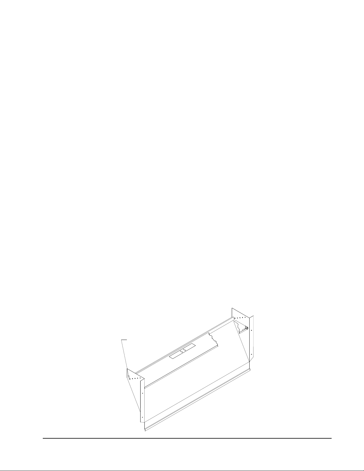
If the unit is equipped with a fresh air damper
assembly, the assembly is shipped already attached
to the unit. The damper blade is locked in the closed
position. To allow the damper to operate, the maximum
and minimum blade position stops must be installed
(see Figure 1).
Graphs found on pages 39 and 40 give approximate
fresh air amounts based on the blade position stop
location.
All capacity, efficiency and cost of operation
information is based upon the fresh air blank-off plate
in place and is recommended for maximum energy
efficiency.
The blank-off plate is available upon request from the
factory and is installed in place of the fresh air damper
shipped with each unit.
FIGURE 1
Fresh Air Damper
BLADE IS LOCKED CLOSED
FOR SHIPPING
MIS-938
Manual 2100-703
Page 5 of 40

INSTALLATION
Basic Installation Design and
Application Planning
Successful unit installations require proper planning
and site inspection before installation begins. Before
installing the wall mount unit, make sure that all
service and airflow clearances are met and that the
unit can meet all applicable code and regulation
requirements. Provide an inspection of both the inside
and outside of the structure by reviewing floorplans and/
or visiting the installation site.
Wall Construction
The wall must be inspected to ensure that the weight
of the unit can be supported. Be sure to review all
applicable construction codes and regulations including
seismic requirements. When inspecting wood frame
walls, the wall construction must be strong and
rigid enough to carry the weight of the unit without
transmitting any unit vibration. It is important that
the side unit wall mounting lags and optional bottom
bracket are supported by structural members inside
the wall cavity. Concrete block and brick walls must be
thoroughly inspected to ensure that they are capable of
carrying the weight of the installed unit. Metal buildings
must contain structural components to support the unit
weight. If heavily corrugated siding is present, it may
need to be trimmed and flashed to provide a flat, even
surface to attach and seal the unit to the wall.
Outdoor Area Inspection
Inspect the outdoor area of the jobsite or review
construction plans and locate the area where the wall
mount is to be installed. The outdoor area must be
free from obstructions including fences, bushes and
walls that will hinder unit operation regarding outdoor
condenser airflow and unit serviceability. Do not
install units in enclosed areas that limit the amount
of ambient temperature airflow. Warm air will exit
the front condenser section of the unit, and outdoor
ambient temperature air must be able to enter side
intake condenser openings of the unit. Portable or
modular building placement must be in a way that the
wall mount units have a constant supply of outdoor air
for proper unit operation. Make sure that the service
panels of the unit are accessible. Inspect wall surfaces
for obstructions that could hinder unit installation
and servicing including outdoor electrical conduits,
junction boxes, wall drains, vent hoods, windows, doors,
overhangs and posts.
NOTE: Before mounting the heat pump unit,
consideration should be given to the
condensate removal from the outdoor coil when
in heating mode. The unit must be mounted
high enough above grade to ensure that ice
will not build up under the unit and come into
contact with the base of the unit. If allowed,
this could cause damage to the coil and other
base components. Also, be sure there are no
air obstructions to the sides or front of the
unit, such as bushes or fences, that would
inhibit condenser airflow.
Condensate Water Drainage
Review all codes and requirements for unit condensate
drainage. A clear, flexible PVC drain hose (3/4" ID, 1"
OD) extends from the drain pan in the upper section of
the unit and extends down to the unit base. An opening
is supplied towards the back of the unit base for the
drain hose to pass through, and the hose extends 1"
to 2" below the unit base. Water removed from the
indoor air (condensate) will be expelled from the unit
in large amounts during cooling operation through the
hose. Units running in cooling operation in cold outdoor
below freezing conditions can cause the condensate
to freeze after leaving the drain hose. In the event the
drain hose is connected to a drain system of some type,
it must be an open or vented type system to ensure
proper drainage throughout seasonal use.
Indoor Ducted and Non-Ducted
Applications
Air distribution inside the structure being conditioned
plays an important role in making sure the area is
a consistent temperature. Improper air distribution
can result in areas being cooler or warmer, electrical
equipment not receiving sufficient airflow or occupancy
discomfort felt inside an area. Thermostat or indoor
temperature sensor placement inside the area being
conditioned also plays an important role in indoor
climate control.
Indoor Supply Airflow
Indoor installation areas must provide a non-restrictive
path for the conditioned supply air to leave supply
grilles and registers. Inspect the area to ensure that all
indoor portions of the room or rooms will have access
to supply air. Ductwork may be used to ensure proper
air circulation and all provided ductwork guidelines and
clearances must be followed. Non-ducted applications
must use a supply louver grille installed over the supply
opening inside the room. Be sure to adjust supply
deflectors to properly disperse the conditioned supply
air to all parts of the room. Avoid closing sections of
the supply grilles which would cause unneeded supply
duct pressurization.
Indoor Return Airflow
A non-restrictive path for room air returning to the
center section of the unit must be provided inside
the room. Avoid placing objects including furniture,
electronics equipment, equipment racks and cabinets
Manual 2100-703
Page 6 of 40
directly in front of the unit return grilles and registers.
Bard recommends at least 2' between solid objects
and return grilles or registers. Ductwork may be used to
ensure proper air circulation and all provided ductwork
guidelines and clearances must be followed. Nonducted applications must use a return louver grille
installed over the return opening inside the room.
Ducted Applications
Field fabricated supply and return duct work may be
installed inside the structure being conditioned. A short
supply and/or return stub duct may be connected to the
unit supply and return flanges before unit installation to
help with duct connections inside the structure. Supply
and return ducts must be properly sized for the design
airflow requirement of the equipment. Air Conditioning
Contractors of America (ACCA) is an excellent guide
to proper sizing. All duct work or portions thereof not
in the conditioned space should be properly insulated
in order to conserve energy, reduce heat conductivity,
and prevent condensation or moisture damage. Refer to
Maximum External Static Pressure (ESP) of Operation
Table 17 on page 36. Design the duct work according
to methods given by the Air Conditioning Contractors
of America (ACCA). When duct work is installed
in unheated spaces, it should be insulated with a
minimum of 1" of insulation. Use insulation with a
vapor barrier on the outside of the insulation. Flexible
joints should be used to connect the duct work to the
equipment in order to keep the noise transmission to a
minimum. Ducts through the walls must be insulated
and all joints taped or sealed to prevent air or moisture
from entering the wall cavity.
The unit itself is suitable for 0" clearance, but the
supply air duct flange and the first 3' of supply air duct
require a minimum of 1/4" clearance to combustible
material for model series W30 and W36. However, it
is generally recommended that a 1" clearance is used
for ease of installation and maintaining the required
clearance to combustible material. See Figures 3A and
3B on pages 10 and 11 for details on opening sizes.
!
WARNING
Fire hazard.
Maintain minimum 1/4" clearance between the
supply air duct and combustible materials in
the rst 3' of ducting.
Failure to do so could result in re causing
damage, injury or death.
Free Blow Applications
Some installations may not require extensive supply
duct work throughout the structure and are referred
to as free blow applications. A short field-fabricated
supply duct must be used in the wall cavity to
transition between the supply collar on the unit and
the supply louver grille in the room. The duct must
be properly insulated in order to conserve energy,
reduce heat conductivity and prevent condensation or
moisture damage. All joints must be taped or sealed to
prevent air or moisture entering the wall cavity. Follow
all clearances including distances to combustible
materials and all instructions provided in this manual.
A non-restrictive metallic supply air grille with
deflectors is required for free blow applications. Contact
the local Bard distributor or visit www.bardhvac.com for
ordering information.
A metallic return air grille is required for non-ducted
applications. The spacing between louvers on the grille
shall not be larger than 5/8". It is recommended that a
Bard Return Air Grille Kit be installed that is designed
specifically for the wall mount product. Contact the
local Bard distributor or visit www.bardhvac.com for
ordering information. A field-supplied return grille
that meets the 5/8" louver criteria and does not cause
the unit to exceed the maximum specified external
static pressure (ESP) may be used. If using a return
air filter grille, filters must be of sufficient size to
allow a maximum velocity of 400 fpm. Filter return
air grilles do not filter air being brought into the
structure through ventilation options including fresh air
dampers, ventilators, economizers and energy recovery
ventilators. Be sure to install the return grille with the
louvers pointed downward towards the floor. This will
help ensure return air is drawn upward from the floor
and improve air circulation in the room.
NOTE: If no return air duct is used, applicable
installation codes may limit this cabinet to
installation only in a single story structure.
Thermostat or Indoor Temperature Sensor Placement
The location and installation of the thermostat or
temperature sensor that monitors indoor temperature is
very important regarding unit operation. Avoid placing
the thermostat in an area exposed to direct sunlight
or air from doorways leading outdoors. Use a piece
of insulating material to close off conduit openings
or holes in the wall surface for wire entry into the
thermostat or temperature sensor. This will help avoid
non-conditioned air from entering the thermostat
and effecting temperature and/or humidity readings.
As common practice, the thermostat or temperature
sensor should measure the temperature of the air
being returned to the unit, and not the conditioned
air being supplied by the unit. Placing the thermostat
or temperature sensor near a return air opening will
normally result in optimal unit performance.
Manual 2100-703
Page 7 of 40

Unit Installation
Make sure to have the proper tools at the work site that
are needed for unit installation. The following steps
are provided to ensure the unit is installed properly to
the wall surface, and that the unit will provide years of
service with minimal service requirements.
Materials/Tools List
Additional hardware and miscellaneous supplies are
needed for installation. These items are field supplied
and must be sourced before installation. This list also
includes tools needed for installation.
• Appropriate safety gear including gloves and safety
glasses
• 5/16" hex bit with drill driver
• Phillips head screwdriver
• Small straight (thermostat) screwdriver
• Tape measure
• Leveling device
• Two (2) tubes of caulk and caulk gun
• Utility knife
• Tools for cutting holes in the wall surface (if
needed)
• Electrical components and wiring along with
electrical tools
• Multimeter
• Wall fasteners for side flanges, bottom mounting
bracket and top rain flashing.
• Duct tape and/or other duct sealing materials.
Wall Preparation
1. Two holes for the supply and return air openings
must be cut through the wall as shown in
Figures 3A and 3B on pages 10 and 11. Be sure
the openings are square and level. Follow all
clearances including distances to combustible
materials and all instructions provided in this
manual.
2. Review all electrical requirements provided in this
manual and plan out electrical entrances into the
building. Also plan electrical conduit routing and
thermostat placement, if necessary.
3. Install necessary duct work and prepare the
openings for unit installation.
4. Clean the exterior wall where the unit is to be
installed and make sure it is able to provide a
smooth, level, debris-free surface. Remove all
construction debris from the supply, return and
electrical hole cutting process.
Wall Mount Installation to Wall Surface
Remove packaging from unit and make sure unit
1.
is not damaged before installation. A top rain
flashing is supplied for field use and is mounted
to the back of the unit for shipping. Remove rain
flashing before locating the unit against wall. Top
rain flashing is required to avoid water entering
the area behind the unit that is against the wall. A
bottom mounting bracket, attached to the skid for
shipping, is provided for ease of installation but is
not required. Review all requirements listed on unit
labels and on serial plate located on the side of the
unit.
2. Locate and mark bolt hole locations and bottom
mounting bracket location. Install bottom mounting
bracket with field-supplied fasteners to wall if it is
to be used (optional). Bracket must be level and
installed in the correct location to help support the
unit during the installation process (see Figures 3A
and 3B).
3. Position the wall mount unit close to the wall
surface where it will be installed. Install rain
flashing at the top of the unit facing the wall by
hooking the hem bend into the rear bend of the
unit top (see Figures 3A and 3B).
4. Apply a liberal amount of caulk on left and right
cabinet side wall mount brackets and back of
top rain flashing. Place unit back surface flush
against wall. Unit must be level to ensure proper
condensate drainage. Optional bottom bracket may
be used to help support the unit.
5. Units are secured to the wall by using fieldsupplied fasteners along each side of the wall
mount through the built-in wall mounting brackets.
It is the responsibility of the installer to select the
proper fastener to secure the unit to the wall based
on wall construction and applicable building codes.
Typical installations may include 5/16" fasteners
with 7/8" diameter flat washers. Be sure unit is
securely mounted and all weight-bearing fasteners
are attached to the weight supporting structural
members of the wall.
6. Apply a bead of caulk between the back of the unit
top and the front surface of the top rain flashing
(see Figures 3A and 3B).
7. Connect unit duct work from the inside of the
building following all clearances and instructions
provided. For additional mounting rigidity, the
return air and supply air frames or collars can be
drilled and screwed or welded to the structural wall
itself (depending upon wall construction). Be sure
to use code approved duct tape or other sealing
materials to seal the duct work to the unit.
8. On side-by-side installations, maintain a minimum
of 20" clearance on right side to allow access to
control panel and heat strips, and to allow proper
airflow to the outdoor coil. Additional clearance
may be required to meet local or national codes.
Manual 2100-703
Page 8 of 40
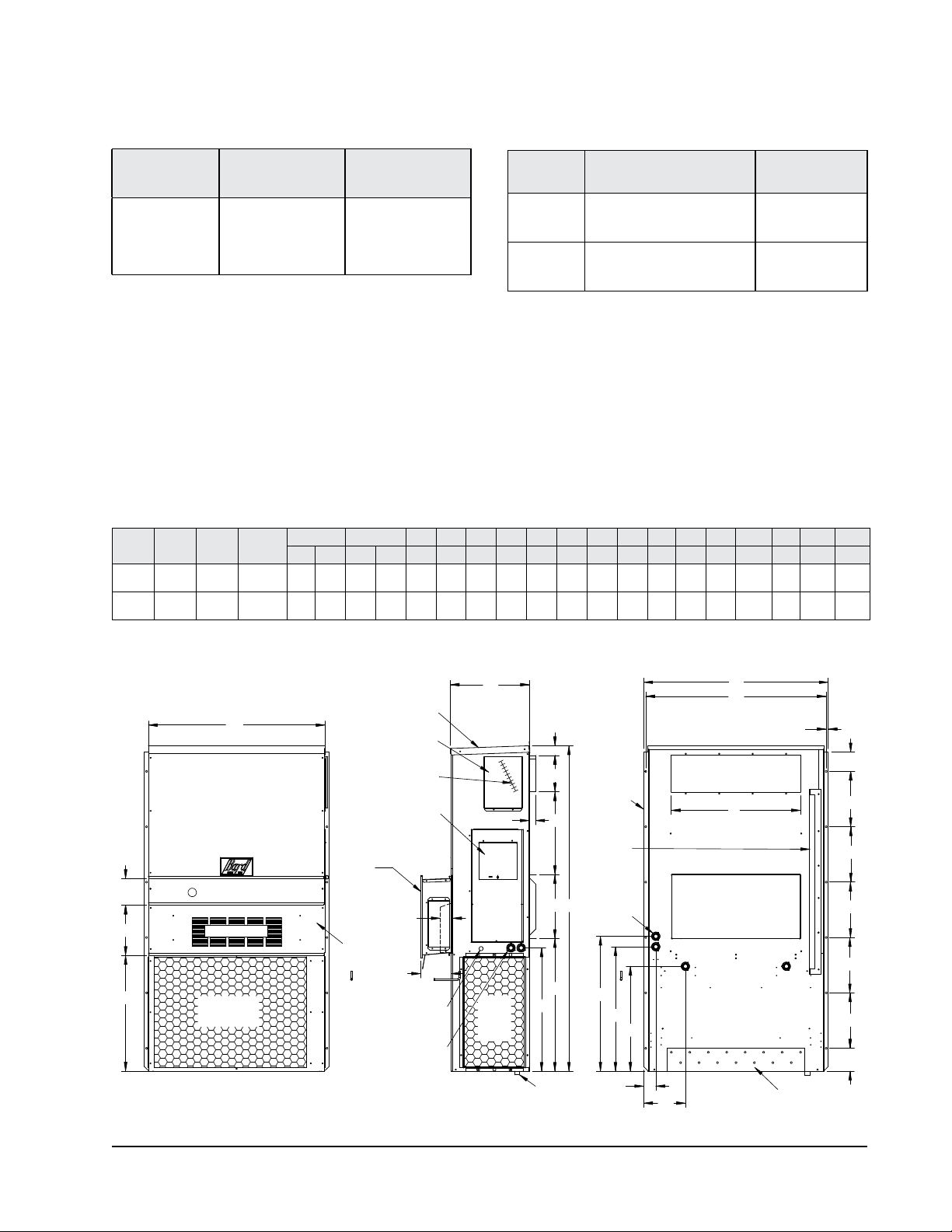
TABLE 1
Clearance Required for Service Access and
Adequate Condenser Airflow
TABLE 2
Minimum Clearances Required
to Combustible Materials
Model
W18H
W24H
W30H
W36H
Left
Side
15" 20"
Right
Side
Model Supply Air Duct (1st 3') Cabinet
W18H
W24H
W30H
W36H
0" 0"
1/4" 0"
1. Follow all national, state, and local codes and regulations regarding the installation of heating and cooling equipment regarding Single
Packaged Vertical Units (SPVU) including electrical access clearances.
2. Field ventilation installation with the unit installed requires 40" on the left or right side of the unit.
3. Bard recommends a minimum of 10' between the unit front condenser air outlet and solid objects including fences, walls, bushes and
other airflow obstructions.
4. Bard recommends a minimum of 15' between the condenser air outlets of two units that are facing each other.
5. Bard recommends a minimum clearance of 4" under the unit cabinet for condenser defrost drain age during heat pump operation.
FIGURE 2
Unit Dimensions
Width
Depth
(W)
W18HB
33.300 17.125 74.563 7.88 19.88 11.88 19.88 35.00 10.88 29.75 20.56 30.75 32.06 33.25 31.00 2.63 34.13 26.06 10.55 4.19 12.00 9.00
W24HB
W30HB
38.200 17.125 74.563 7.88 27.88 13.88 27.88 40.00 10.88 29.75 17.93 30.75 32.75 33.25 31.00 2.75 39.13 26.75 9.14 4.19 12.00 9.00
W36HB
Height
(D)
All dimensions are in inches. Dimensional drawings are not to scale.
Supply Return
(H)
A B C B E F G I J K L M N O P Q R S T
5.88
F
G
W
Filter AccessPanel
1
Ventilation Air
Condenser
Air Outlet
Front View
Rain Hood
C. Breaker/
Disconnect
Access Panel
(Lockable)
Hood for CRVand
ECON models
only
Standard
flush vent
door for nonERV/CRV
Econ.
models
Low Voltage
High Voltage
Built In
4° Pitch
Heater
Access
Panel
Electric
Heat
3"
7.00
Electrical
Entrance
Electrical
Entrance
D
1.250
Cond.
Air
Inlet
Side View
2.13
J
Drain
E
O
.44
Side Wall
A
Mounting
Brackets
(Built In)
I
Top Rain
Flashing
Shipping
Location
Optional
C
Electrical
H
Entrances
K
L
M
P
N
Supply Air Opening
B
Return Air Opening
Back View
Q
Bottom Installation
Bracket
R
S
S
S
S
S
T
MIS-3796
Manual 2100-703
Page 9 of 40
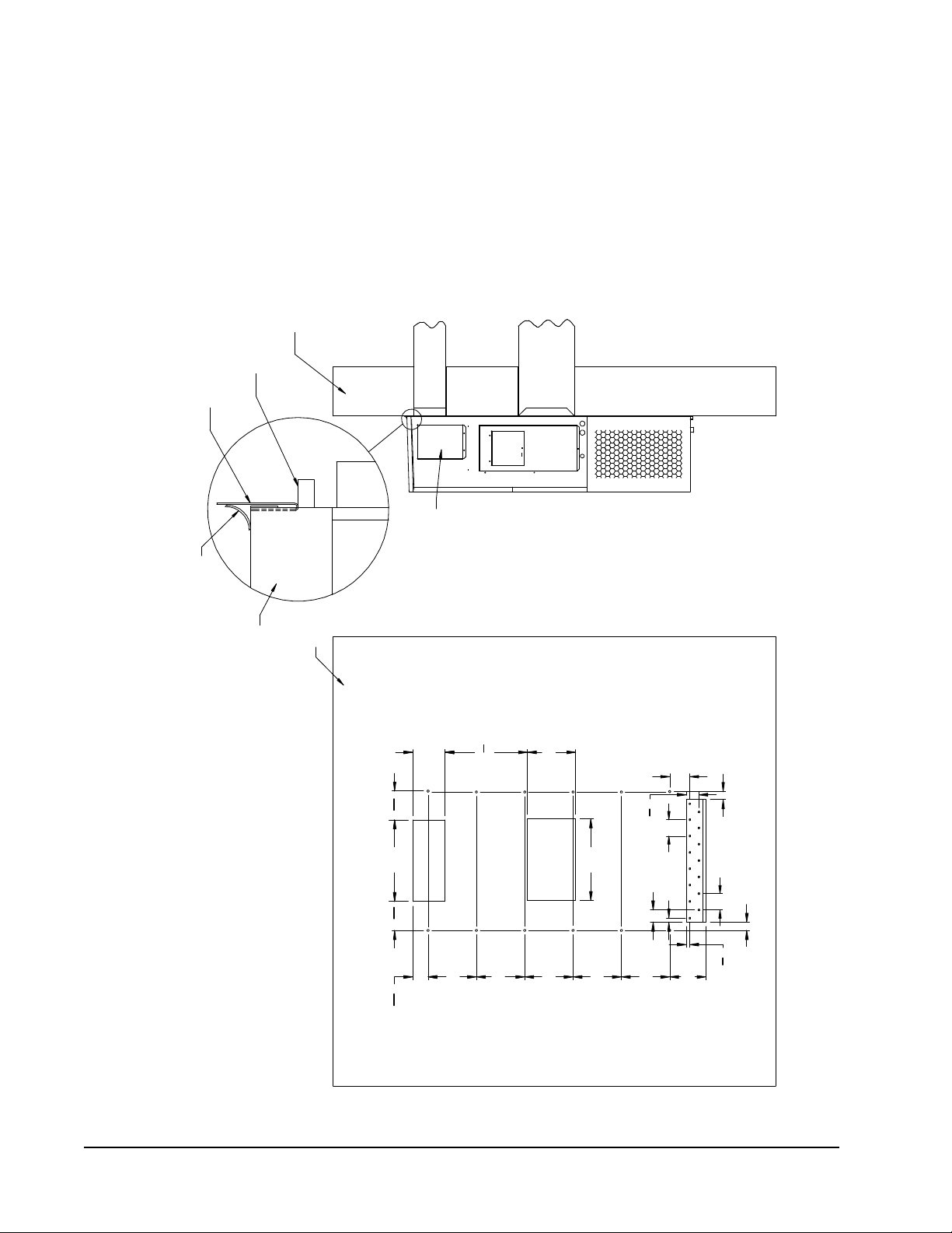
12"
12"
12"
12"
12"
20"
20"
8"
20
1
2
"
12"
3
13
16
"
2"
2"
7
1
16
" 7
1
16
"
5"
1"
3"
4"
Typ.
3
1
8
"
4"
Typ.
7
8
"
9"
NOTES:
WALL STRUCTURE
ENTIRE LENGTH OF TOP.
TOP
WALL
OF CAULKING ALONG
PANEL
FOAM AIRSEAL
DUCT
RAIN FLASHING
HEATER ACCESS
MIS-3157 A
Wall Opening and Hole Location View Right Side View
RETURN AIR
TOP FLASHING ATTIME OF INSTALLATION.
OPENING
THE SIDEMOUNTING FLANGES ANDUNDER
SEAL WITHBEAD
IT IS RECOMMENDEDTHATA BEAD OF
SILICONE CAULKING BEPLACED BEHIND
SUPPLY AIR
SUPPLIED
Return Opening
Supply Opening
J**A UNIT SHOWN, J**L UNIT
CONTROLS AND HEATERACCESS
IS ONOPPOSITE(LEFT) SIDE.
FIGURE 3A
W18H, W24H
Mounting Instructions
Manual 2100-703
Page 10 of 40
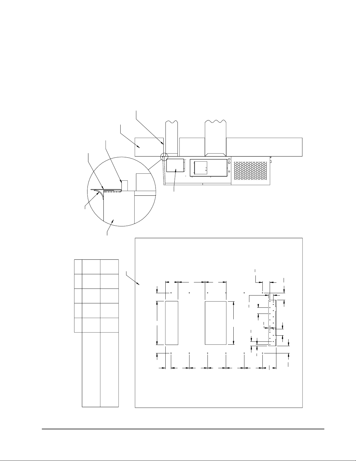
28"
A C
D
C
12"
12"
12"
12"
12"
B
E
14"
4
11
16
"
4
11
16
"
4"
Typ.
2
7
8
"
7
8
"
7
8
"
" 3
1
8
4"
Typ.
9
1
16
"
4
7
8
"
MATERIALS
RAIN FLASHING
RETURN AIR
TOP
SILICONE CAULKING BE PLACED BEHIND
SUPPLIED
ENTIRE LENGTH OF TOP.
NOTES:
OF CAULKING ALONG
PANEL
FOAM AIR SEAL
WALL STRUCTURE
FOUR SIDES OF SUPPLY
AIR DUCT IS REQUIRED
SUPPLY AIR
OPENING
MIS-3158 A
Right Side View
1/4" CLEARANCE ON ALL
DUCT
THE SIDE MOUNTING FLANGES AND UNDER
HEATER ACCESS
TOP FLASHING AT TIME OF INSTALL ATION.
FROM COMBUSTABLE
SEAL WITH BEAD
IT IS RECOMMENDED THAT A BEAD OF
WALL
Wall Opening and Hole Location View
REQUIRED DIMENSIONS TO MAINTAIN
Return Opening
16 7/84 7/164 5/89 7/829 7/8
17 5/83 11/165 3/88 3/828 3/8
EDCBA
COMBUSTIBLE MATERIALS
RECOMMENDED 1" CLEARANCE FROM
REQUIRED DIMENSIONS TO MAINTAIN
COMBUSTIBLE MATERIALS
1/4" MIN. CLEARANCE FROM
Supply Opening
J**A UNIT SHOWN, J**L UNIT
CONTROLS AND HEATER ACCESS
IS ON OPPOSITE (LEFT) SIDE.
FIGURE 3B
W30H, W36H
Mounting Instructions
Manual 2100-703
Page 11 of 40
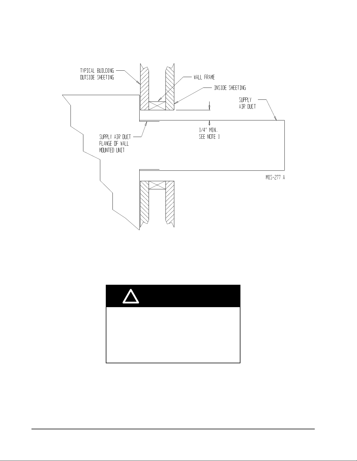
FIGURE 4
Electric Heat Clearance
W30H and W36H
SIDE SECTION VIEW OF SUPPLY AIR DUCT FOR
WALL-MOUNTED UNIT SHOWING 1/4" CLEARANCE
TO COMBUSTIBLE SURFACES.
!
WARNING
Fire hazard.
Maintain minimum 1/4" clearance between the
supply air duct and combustible materials in
the rst 3' of ducting.
Failure to do so could result in re causing
damage, injury or death.
Manual 2100-703
Page 12 of 40
 Loading...