


WALL MOUNTED
REPLACEMENT
PARTS MANUAL
General Notes
Revised and/or additional pages may
be issued from time to time.
A complete and current manual
consists of pages shown in the
following contents section.
Important
Contact the installing and/or
local Bard distributor for all parts
requirements. Make sure you have
the complete model and serial
number available from the unit rating
plates.
PACKAGE
AIR CONDITIONER
Models:
Contents
Description Page
Cabinet Components
Exploded View ........................ 2
Functional Components
Exploded View ........................ 4
Usage List ............................... 5
Control Panel
Exploded View ........................ 6
Usage List ............................... 7
Blower Assembly
Exploded View ........................ 8
Usage List ............................... 8
W17L2, W18L2, W24L2
Usage List ............................... 3
Bard Manufacturing Company, Inc.
Bryan, Ohio 43506
Since 1914...Moving ahead, just as planned.
Manual: 2110-1408B
Supersedes: 2110-1408A
File: Tab 16
Date: 11-05-13
Manual 2110-1408B
Page 1 of 8
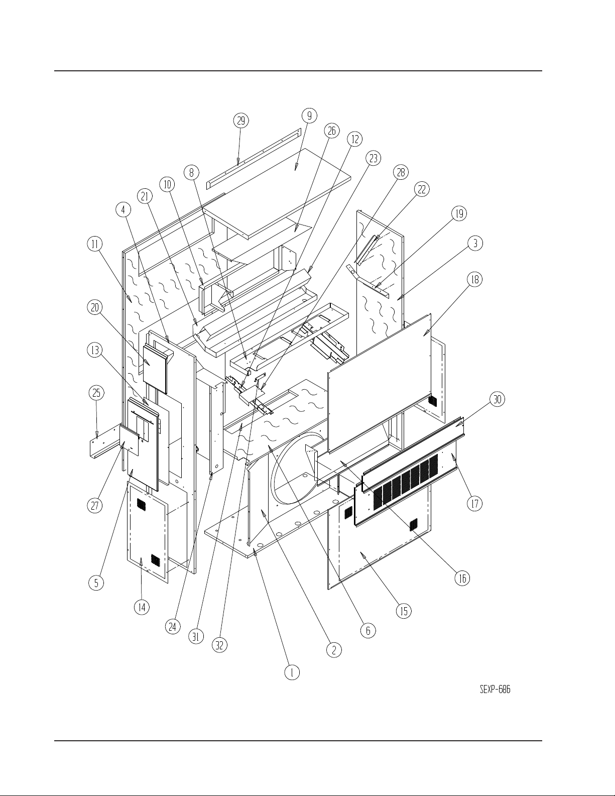
CABINET COMPONENTS
Manual 2110-1408B
Page 2 of 8
CABINET COMPONENTS
Dwg No. Part Number Description
1
1
2
2
3
3
4
4
5
5
6 S521Y479 Condenser Partition X X X
8 121Y480 Blower Partition X X X
9
9
10 S111Y032 Outlet Air Frame Assembly X X X
11
11
12 113Y480 Filter Bracket 2 2 2
13 S132-104 Control Panel Cover (Inner) X X X
14
14
15
15
16 BFAD-2 Fresh Air Damper Assembly X X X
17
17
18
18
19 105Y850 Side Support X X X
20
20
21
21
22 147-044 Evaporator Support X X X
23 137-694 Bottom Evaporator Fill X X X
24 Control Panel Assembly See Control Panel Assy. Drawing & Parts List Assy. X X X
25 113-140 Bottom Mounting Bracket X X X
26 135Y127 Heat Shield X X X
27
27
28 137-259 Fill Plate X X X
29
29
30
30
31 S536-176 Cond. Partition Block Off Plate X X X
32 105-1302 Grommet Retainer X X X
S127-468
S127-470 k
125-023
125-056 k
S501-710-*
S501-724 k
S501-685-*
S501-725 k
S533-228
S533-235 k
S507-311-*
S507-317 k
S508-097
S508-220 k
118-056-*
118-067 k
118-051-*
118-077 k
S553-537-*
S553-547 k
S514-240-*
S514-236 k
S543-175-*
S543-185 k
S123-131
S123-142
S153-218
S153-405 k
113-141-*
113-361 k
S553-538-*
S553-551 k
k
Lower Base
Lower Base
Fan Shroud
Fan Shroud
Right Side
Right Side
Left Side
Left Side
Control Panel Cover (Outer)
Control Panel Cover (Outer)
Top
Top
Back
Back
Side Grille
Side Grille
Condenser Grille
Condenser Grille
Vent Option Door
Vent Option Door
Upper Front
Upper Front
Right Side Cover Plate (Outer)
Right Side Cover Plate (Outer)
Drain Pan
Drain Pan
Disconnect Access Door
Disconnect Access Door
Top Rain Flashing
Top Rain Flashing
Filter Door
Filter Door
W17/18L2-A
XXXXX
XXXXX
XXXXX
XXXXX
XXXXX
XXXXX
XXXXX
22222
XXXXX
XXXXX
XXXXX
XXXXX
XXXXX
XXXXX
XXXXX
XXXXX
W24L2-A, -B
W24L2-F
X
X
X
X
X
X
X
2
X
X
X
X
X
X
X
X
Exterior cabinet parts are manufactured with various paint color options. To ensure that you receive the proper paint color, you must include the
complete model and serial number of the unit for which cabinet parts are being ordered.
k Note: Exterior cabinet parts are manufactured from stainless steel Code "S"
Manual 2110-1408B
Page 3 of 8

FUNCTIONAL COMPONENTS
Manual 2110-1408B
Page 4 of 8

FUNCTIONAL COMPONENTS
W17L2-A
W18L2-A
Dwg No. Part Number Description
1
1
1
1
1
2
2
3 8200-001 Fan Motor Mount X X X X X X
4 5151-033 Fan Blade X X X X X X
5 8103-016 Condenser Motor X X X X X X
6
6
7
7
7
8
8
8
9
9
9
10 1171-022 1/4" Turn Fastener X X X X X X
11 1171-024 1/4" Turn Retainer X X X X X X
12 1171-023 1/4" Receptacle X X X X X X
13 5204-001 Subcooling Heat Exchanger X
NS 1804-0385 High Pressure Switch (Flare) X X X X X X
NS 1804-0386 Low Pressure Switch (Flare) X X X X X X
NS CMA-28
NS 5201-021 Filter Drier X X X X X X
8000-313
8000-314
8000-316
8000-315
8000-317
S900-326
S900-291
5051-184BX
5051-185BX
800-0427
800-0428
800-0437
917-0218BX
917-0219BX
917-0220BX
7004-011
7003-032
7004-025
Compressor
Compressor
Compressor
Compressor
Compressor
Blower Assembly
Blower Assembly X X
Condenser Coil
Condenser Coil
Distributor Assembly
Distributor Assembly
Distributor Assembly X
Evaporator Coil with Distributor Assembly
Evaporator Coil with Distributor Assembly
Evaporator Coil with Distributor Assembly
Air Filter 1" Throw-Away
Air Filter 1" Washable
Air Filter 2" Pleated
Low Ambient Control (Flare)
X X
X X
X
X
X
X
W24L2-A
X
X X X X
X X X X
X
X X X X
X
X X X X
X
X
X
X
X
X
X X X X
W24L2-D
W24L2-B
X
X
X
X
X
X
X
X
W24L2-F
X
X
X
X
NS – Not Shown
– Optional on these models
Manual 2110-1408B
Page 5 of 8

CONTROL PANEL
SEXP-687
9
18
17
6
13
11
14
10
16
8
2
4
7
5
3
1
Manual 2110-1408B
Page 6 of 8

CONTROL PANEL
Dwg No. Part Number Description
1 8607-034 Low Voltage Terminal Strip X X X X
2
2
3 8201-009 Blower Control Relay 2 X X X
4 8407-034 Transformer X X X X
5
5
6
6
6
7 135-122 Wire Shield X X X X
8 8611-006 Ground Terminal X X X X
9 3000-968 6 Pin Connector X X X X
10 8201-088 Compressor Control Module (Opt.) X X X X
11 8201-062 Alarm Relay (Optional) X X X X
13 8607-017 Terminal Block (Optional) X X X X
14 8551-004 Start Device (PTCR) (Optional) X X X X
16 117Y137 Control Panel T op X X X X
17 117Y123 Control Panel X X X X
18 8201-126 Phase Monitor X X
NS 8615-035
NS 8615-036
NS 8615-067
NS 8615-056
NS 4095-170 Wiring Diagram X
NS 4095-169 Wiring Diagram X
NS 4095-260 Wiring Diagram X
NS 4095-636 Wiring Diagram X
8607-013
8607-014
8401-007
8401-002
8552-046
8552-047
8552-002
Terminal Block 2 Pole
Terminal Block 3 Pole
Compressor Contactor
Compressor Contactor
Compressor Capacitor
Compressor Capacitor
Outdoor Motor Capacitor
Circuit Breaker 20A 2 Pole (Opt.)
Circuit Breaker 25A 2 Pole (Opt.)
Toggle Disconnect (Optional)
Circuit Breaker 15A 3 Pole (Opt.)
W17/18L2-A
X X
X X
X
X
X
X
W24L2-A, -D
W24L2-B
W24L2-F
2
X
X X
X X
X
X
NS = Not Shown
Circuit breakers listed are for units without electric heat, “0Z” models. Hot gas bypass models not available
without electric heat. See Heater Replacement Parts Manual for units with electric heat.
Manual 2110-1408B
Page 7 of 8

BLOWER ASSEMBLY
Manual 2110-1408B
Page 8 of 8
Dwg No. Part Number Description
1 151-115 Housing 2 2
2 144-183 Cutoff X X
3
3
4
4
5 8200-031 Motor Mount X X
6 5451-011 Grommets 6 6
7 105-1061 Back Brace X X
8 103-435 Front Brace X X
9 5152-092 Wheel 9-6 CW X X
10 5152-093 Wheel 9-6 CCW X X
8102-016
8102-014
8552-002
8552-004
Blower Motor (230/208)
Blower Motor (230/208)
Capacitor
Capacitor X
S900-326
S900-291
X
X
X
 Loading...