

Page 1
|
|
|
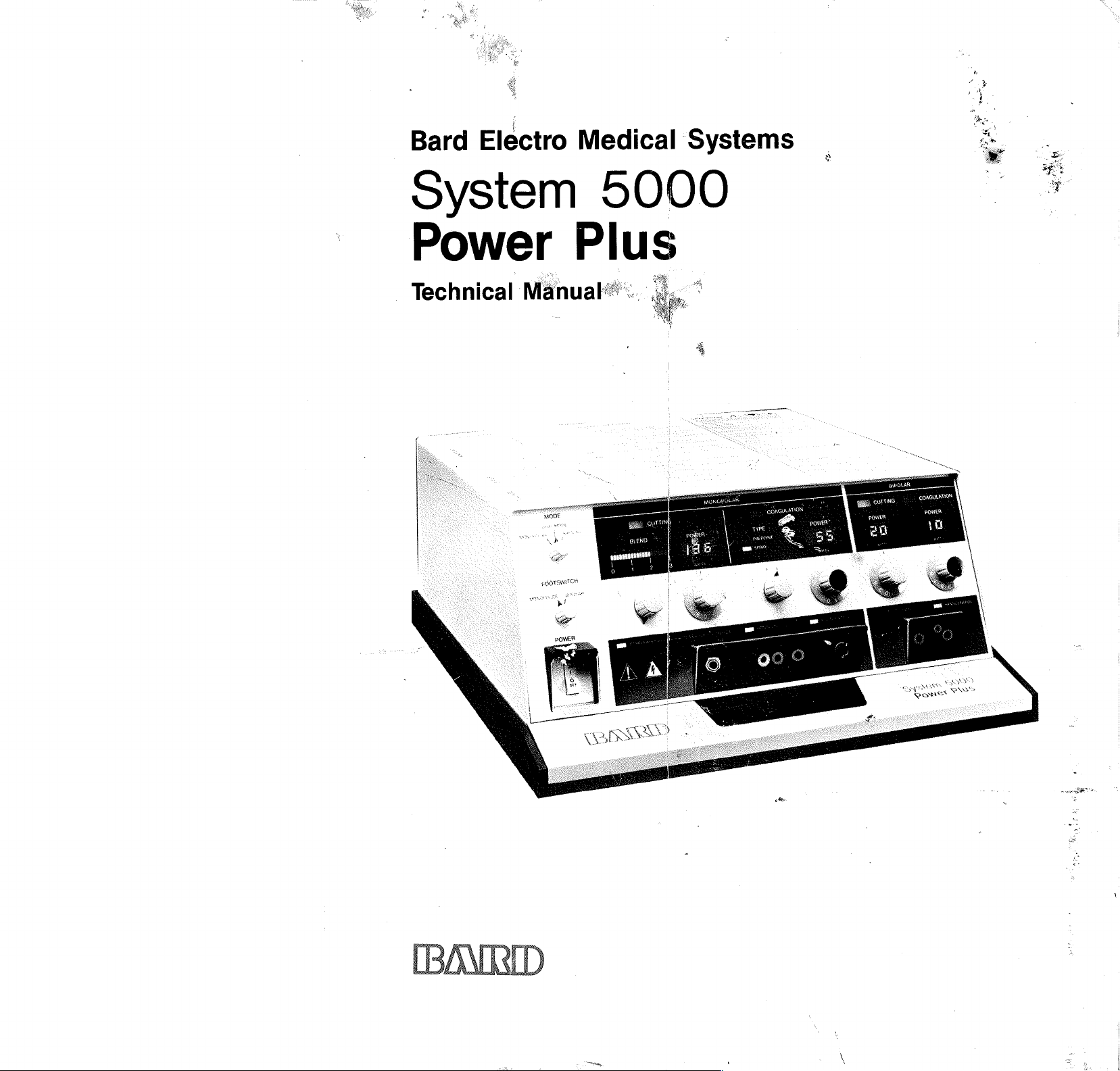
Bard
Electro
System
Power
Medical
Systems
5000
Plus
OTO
OR
UO 1 i
PO
E
==
MER”
Da
いい
te
CORGULATION
P
-
sit
가
>
Page 2
System
5000
Electrosurgical
Preface
The
System
for
use
functions
and
convenience.
The
System
spray.
areas.
-tissues
that
allows
hemostasis.
For
your
calibrated
unit
has
isolated
5000
in
the
modern
to
satisfy
5000
Pinpoint
Spray
over
coagulation
coagulation
broad
you
to
convenience,
in
watts
totally
separate
R.F.
output.
Power
Generator
Power
operating
all
of
your
Power
provides
surface
set
the
the
with
large,
bipolar
Plus
Plus
room.
surgical
Plus
provides
areas.
exact
power
power
illuminated
controls,
is a multi-purpose
It
demands
offers
two
precise
greater
This
unit
desired
output
features
control
of
digital
discrete
levels
control
also
offers
for
the
System
displays.
both
with
of
of
pure
output,
electrosurgical
monopolar
safety,
of
bleeding
flexibility,
coagulation,
bleeding
infinitely
cut
or
5000
For
your
cord
and
pinpoint
in
localized
in
highly
variable
cutting
Power
safety
fault
generator
alarm
bipolar
reliability
and
vascular
blend
with
Plus
is
this
and
Page 3
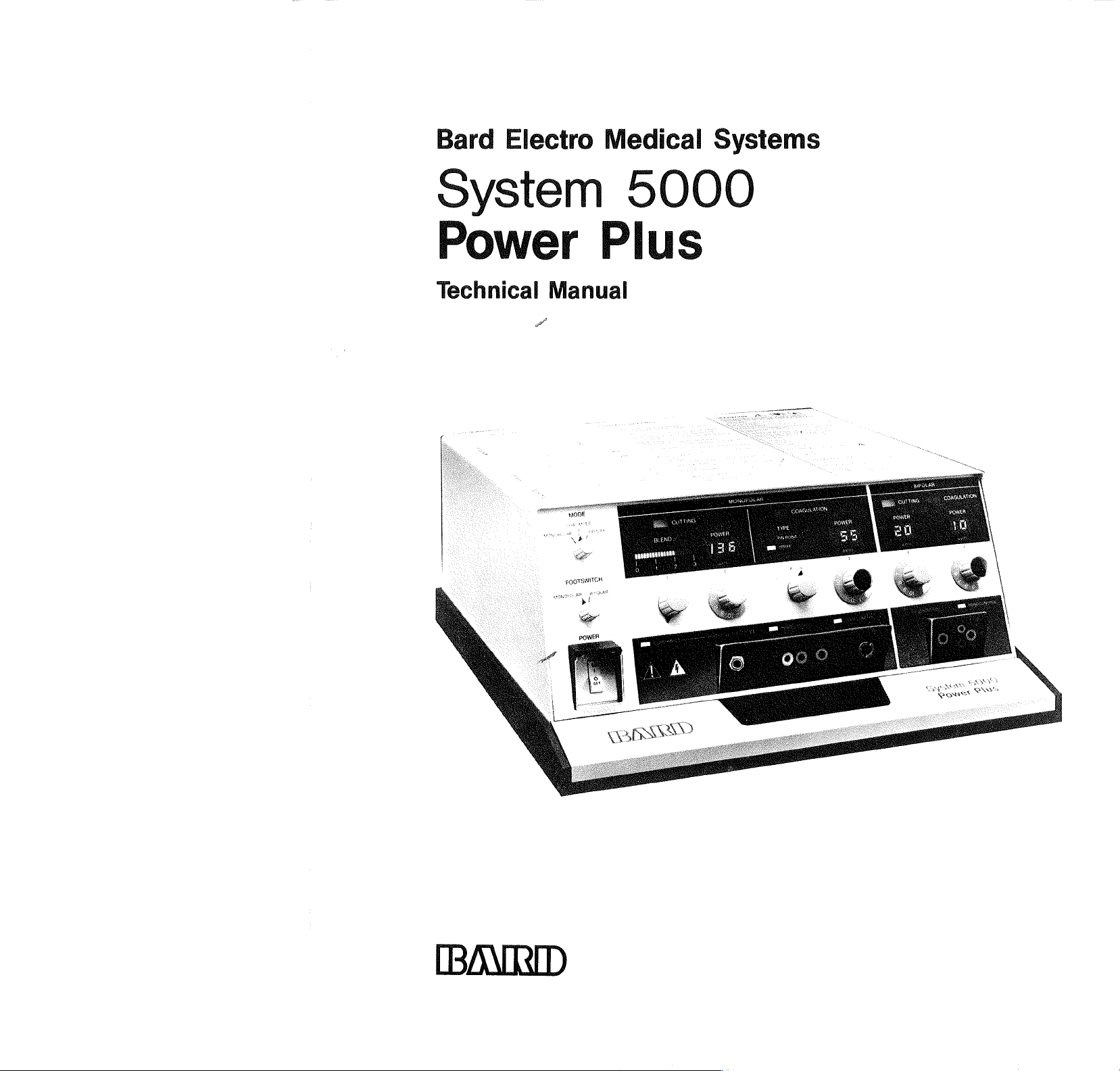
Bard
Electro
Medical
Systems
System
Power
Technical
Manual
A
5000
Plus
POWER
JMD
Page 4
Table
of
Contents
Specifications
Foreword.
Limited
General
Safety
Warranty. . .
Information
PrecautionS.
Description
General
I.
II.
. . . ...
Modes . 4, « ὁ
A.
B.
Functional.
A.
B.
C.
D.
E.
Е.
(Table
. . . . »
. . .
Monopolar
1.
Pure
2.
Blend.....
3.
Pin
4.
Spray
Bipolar
1.
Bipolar
2.
Bipolar Cutting
Mode
Switch . . . .
1.
Monopolar
2.
Bipolar
3.
Dual
Footswitch
Blend
Coagulation
Safety
Operational
Control
Considerations
III.
Operational
A.
Monopolar
1.
Pure
Operation.
2.
Blend
3.
Pin
Operation
4.
Spray
Operation
B.
Bipolar
1.
Bipolar
Operation
2.
Bipolar Cutting
Operation . .
Installation. . .
I.
II.
III.
IV.
Unpacking . 2.
Assembly. . . « « +
Environmental
Operational
1-1). . . . .
e e
s © » e e e
. . « + + « + Xi
. .
. . . . . .
. . . .
. + + «e
0
e e e e e
0 0 0 0
ὁ ο ὁ ο ο ο
…
Cutting.
Point
Coagulatio
Coagulation
.......
Coagulation
. ,
2.
. .
Positions
Position.
Mode
Position. . 1-2
Selector
......
Type
Selector
Features
.....
Mode
.....
Modes
......
. . . , . . . .
Cutting
.....
Operation...
Point
Coagulation
+.
. . . . . 1-5
Coagulation
+. . » .
..
o...
Coagulation
. . . . . ,
. . . . .
% « 4 6
«
Requirements.
Set-Up.
....
Xİİ
. . « Xiii
I-İ
0 + + 1-1
Κω
ο ο
e ο
エー
.
5
Dee
©
.
5 e
エー
ヒート
に
ヒー
トー
トー
ヒー
ーー
1-2
1-2
...
.
. .
. . . .
. . .
1-2
. .
1-2
. . .
1-3
1-3
1-3
1-4
1-4
1-4
1-4
1-4
1-5
. .
1-6
ooo.
1-6
1-6
. . . .
. . . .
44
+
1-7
2-1
2-1
2-1
2-2
2-2
1
Xi
-
-
-
4
pe
e
A
ps
AA
A
NO
Operation
I.
11.
111,
IV.
V.
(Operator's
General
Controls,
Accessory
Checkout.
Service
Glossary. « cc
Maintenance . .
I.
II.
III.
IV.
V.
VI.
Introduction. . . .
Field
General
A.
B.
Repair
Access.
Cleaning.
Functional
Performance
Calibration...
A.
Introduction.
B.
Information
Before
Calibration...
С.
Preliminary
0.
System
Procedures. . + . . . . . 4-3
1.
2.
3.
4.
5.
VIT.
Troubleshooting
A.
Introduction,
B.
Information
Prior
Troubleshooting
C.
Troubleshooting
Visual
Operation . . . . . . .
D,
Troubleshooting
RF
Wave
Manual) . . .
Safety
Precautions
Indicators
Connectors.
e ο e o 9 . ο o e
and
. . . .3-23
3-0
3-3
„3-25
Support . . . +... . .3=27
ο ο ὁ ο ο
. . . .
Maintenance
. . ο ㆍ 9 ㆍ φ 9 9
«e
and
Warranty . .
. . . . . . +
Check. . , . .
Checks.
1.
...
to
« e e + +
. .
.....
. . . . .
. , , . .
Consider
. .
3-29
. .
.
4-1
4-1
4-1
4-1
4-1
del
4-2
4-2
4-2
4-2
Performing
. .
4-2
Checkout.
5000
Calibration
Confirm
Preliminary . 4-3
Calibration
Cards
Location
Cards
page
Front
LED
A3,A10,A9
of
Fig.
6-3. . ,
Panel
Digital
Module
Module
6-1,
(A3)
Display
. +
A8. . 4-4
on
. . . .
4-3
4-4
Calibration , , . . , 4-4
System
Plus
Alignment
5000
Power
Power
Output
.....
.
4-6
, . . , . .4-13
to
Consider
to
.
.
.4-13
Methods-
and
Functional
4-14
Methods-
Output
(Power
and
Forms) , . . , 6
.
4-15
Page 5
E.
F.
G.
H.
I.
VIII.
IX.
Remove
Cards
Preventive
Theory
Mnemonic
I.
II.
III.
IV.
Introduction.
Functional
Sub-Assembly
Description . . . « . . .
I.
Schematic
*
*
.
*
«
・
+
+
*
*
Troubleshooting
Voltage
and
Measurements
Signal
Tracing. . .
Application
Protect
Circuits.
System
RF
Figure
4-12.
CMOS
......
5000
Output
Waveforms
4-5
through
. . 0 ὁ ο ο ο ο ο
Troubleshooting
Guide
Of
Operation . . . . +
List
(Table
and
Replace
and
Sub-Assemblies.
Maintenance.
(Table
5-1} , . , ,
.
Block
Circuit
.
P.S.
Output
P.S.
P.S.
Mode
Front
R.F.
R.F.
В.Е.
Translator
Control
Logic
(A7)
Panel
Logic
(A8)
Driver
Amplifier
ㆍ
Ὁ
.
πας)
ποσο
(Composite)
Sensor
Board.
Diagrams.
Fig.
5-1
System
Functional
Diagram.
Fig.
5-2,
Interconnect
Fig.
5-3,
Sub-Assembly
Diagram.
Fig.
5-4,
Fig.
5-7,
Al0.
.....
Fig.
5-9,
Fig.
5-12,
Fig.
5-15,
Fig.
5-19,
Fig.
5-21,
Fig.
5-22,
All
.
Fig.
5-25,
Block
.
.....
System
Diagram
System
Pictorial
........
P.S.
P.S.
P.S.
Mode
Front
Ε.Ε.
R.F.
Power
Composite
Amplifier . .
Methods-
of
Table
Integrated
5
Power
Plus
Signal
4-1)
...
Module
.
.
.
+..
. . . . . .
Diagram.
(A6).
(A10)
(A9) . .
.
(A3),
.
(A4).
......
.....
....
5000
6000
5000
Output
Translator
.....
Control
Logic
Panel
Logic
Drive
Device
. «
. .
.
В.Е.
.
.
Аб
A9
A7.
A3
A8,
A4,
+.
4-16
4-17/4-18
4-17/4-18
4-19
4-20
4-26
4-28
5-1
5-0
1
σι
—
1
σι
ps
»
OO
!
OS
ere
AAA
NINO
a
©
rot
aran
+
no
5-44
5-47
Fig.
Fig.
(Spray)
Fig.
Relay
Fig.
Diagrams/Parts
Parts,
Information. . .
Component
List
Illustrated
Detail
Fig.
Assembly
Diagram.
Fig.
Packing
Diagram.
Fig.
Pictorial
Fig.
Fig.
A10.
Fig.,
Fig.
Fig.
Fig.
Fig.
All.
Fig.
and
Heat
A13
Sheet 1 of 2 , . .
Fig.
and
Heat Sink
Al3
Sheet 2 0f
Fig.
Fig.
A.L...
Fig.
Relay
Fig.
Output
Fig.
Fig.
Mechanical 。 。
Fig。6-19,Front
Electrical
Fig.
Assembly
Fig.
Fig.
sheet 1 of
Fig.
sheet 2 of
Fig.
sheet 3 0f
Addendum.
.
see.
5-26,
5-27,
R.F.
Output
Fulguration
A2. . . . . . . .
5-28,
5-29,
Lists.
High
Al2
Sensor
Ordering.
Voltage
2...
« « ©
Board
. . . . . . .
....
.
Manufacture!
and
6-1,
Parts
Parts
System
Location
Lists
5000
Pictorial
. . . . . « © « + 6-3
6-2,
System
5000
Pictorial
..
6-3,
6-4,
6-5,
. .
P.S.
6-7,
6-8,
6-9,
6-10,
6-11,
6-11,
...
Top
Diagram.
P.S.
P.S.
.
Control
Mode
R.F.
R.F.
Power
oo
eee
R.F.
Sink
Κ.Ε.
e.
Assembly
. .
Output
Translator
A...
Logic
Logic
A7. . 6
A8. . 6-1
Driver
Device
Driver
Assembly
Driver
Assembly
2...
6-13,
6-14,
R.F.
Sensor
Output
Board
026,
6-15,
High
Voltage
Al2. . . . 2 ws
6-16,
6-17,
6-18,
Fulgeration
(Spray)
Front
Front
A2,
Panel
Panel
. . . .
。
Panel
ss
6-20,
6-21,
6-22,
Chassis
.
.
Sub-
Final
Chassis
Assembly
e
6-22,
Final
Assembly
3.
6-22,
Final
3.
....
“Assembly
A5
5-48
5-49
» «
5-50
Al
5-51
6-1
.
. .
6-1
S
o
Fig.
Sub-
o.
6-4
。
6-5
A6 . 6-6
6
-
A4 . 6-1
.
6-12
. .
6-13
.
6-14
АБ,
6-15
6-16
we
we
6-17
6-18
A3
6-19
。。
。6-20
6-21
+ + + 6-22
. .
6-23
6-24
.
6-25
. +
6-26
10
Page 6
Specifications
System
Performance
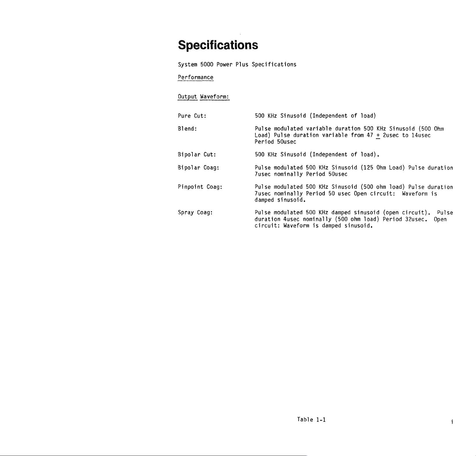
Output
Pure
Blend:
Bipolar
Bipolar
Pinpoint
Spray
5000
Waveform:
Cut:
Cut:
Coag:
Coag:
Power
Coag:
Plus
Specifications
500
Pulse
Load)
Period
500
Pulse
7usec
Pulse
7usec
damped
Pulse
duration
circuit:
KHz
Sinusoid
modulated
Pulse
50usec
KHz
Sinusoid
modulated
nominally
modulated
nominally
sinusoid.
modulated
4usec
Waveform
(Independent
variable
duration
(Independent
500
Period 50usec
500
Period
500
nominally
is
duration
variable
KHz
Sinusoid
KHz
Sinusoid
50
usec Open
KHz
damped
(500
damped
of
load)
500
from
47 + 2usec
of
load).
(125
(500
sinusoid
ohm
load)
sinusoid.
KHz
Sinusoid
Ohm
Load)
ohm
load)
circuit:
(open
Period
(500
to
14usec
Pulse
Pulse
Waveform
duration
duration
circuit).
32usec.
Ohm
is
Pulse
Open
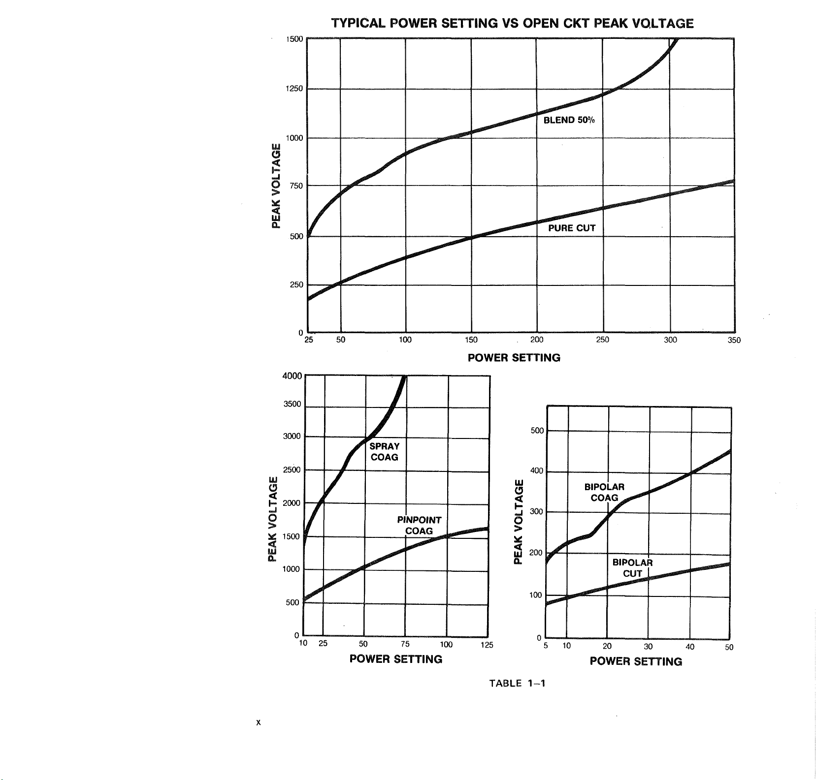
Table
1-1
i
Page 7
Specifications
System
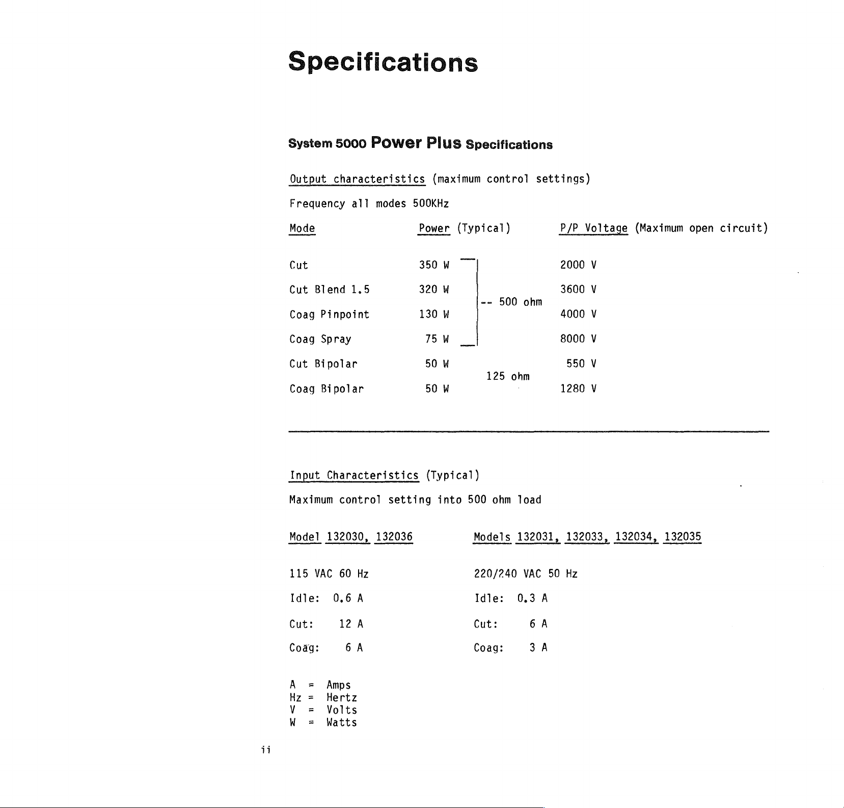
Output
Frequency
Mode
Cut
Cut
Blend
Coag
Pinpoint
Coag
Spray
Cut
Bipolar
Coag
Bipolar
5000
Power
characteristics
all
modes
500KHz
1.5
Plus
(maximum
Power
350
W
320
W
130
W
75 W _
50
W
50
W
Specifications
control
(Typical)
--
500
125
settings)
ohm
ohm
P/P
2000
3600
4000
8000
550
1280
Voltage
V
V
V
V
V
V
(Maximum
open
circuit)
Input
Maximum
Model
115
VAC
Idle:
Cut:
Coag
=
A
Hz
=
V =
W
=
Characteristics
control
132030,
60
Hz
0.6
A
12
A
6A
Amps
Hertz
Volts
Watts
setting
132036
(Typical)
into
500
Models
220/240
Idle:
Cut:
Coag:
ohm
load
132031,
VAC
50
0.3
A
6A
3
À
132033,
Hz
132034,
132035
Page 8
System
5000
Power
Plus
Specifications
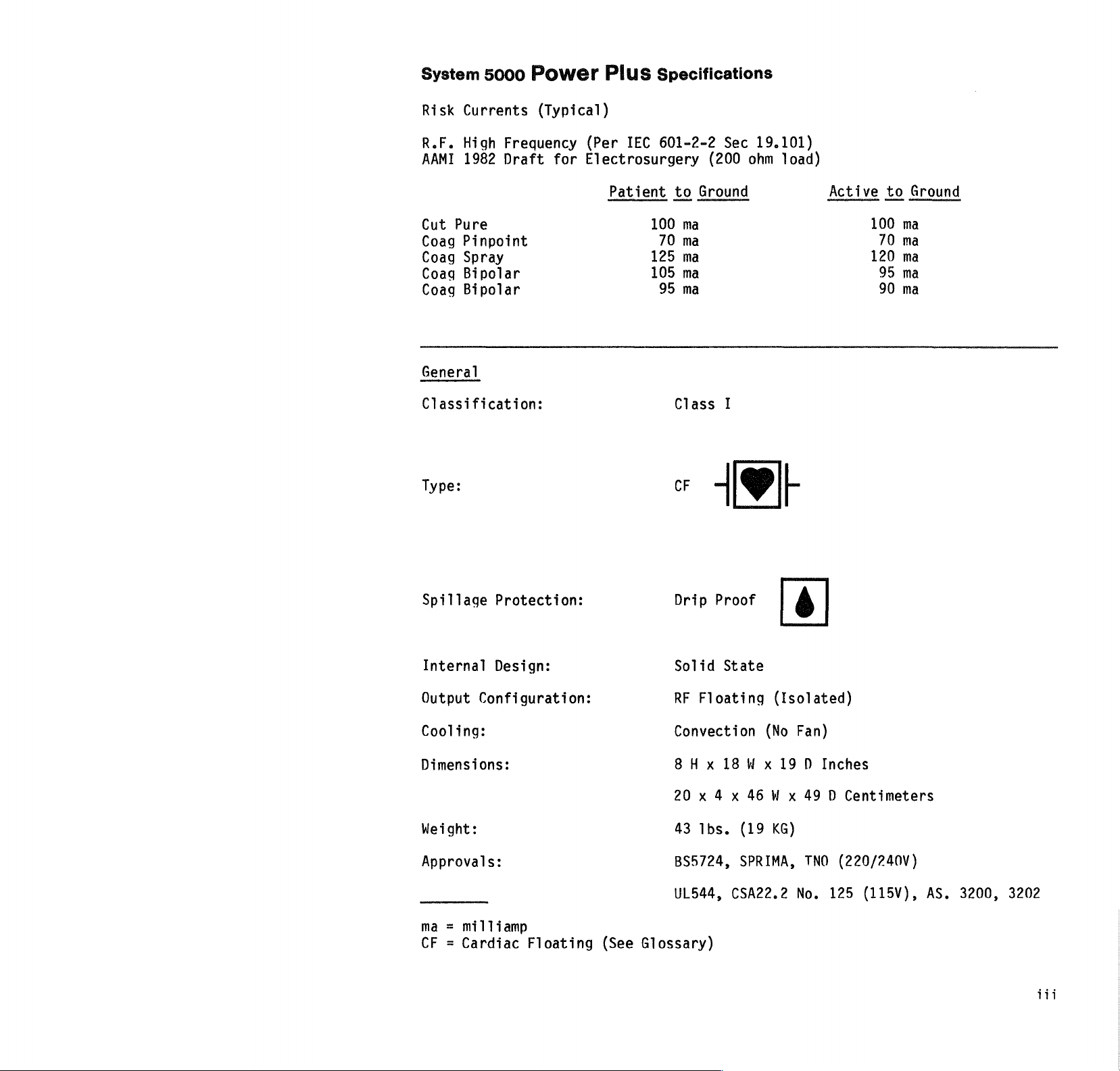
Risk
R.F.
AAMI
Cut
Coag
Coag
Coag
Coag
General
Classification:
Type:
Currents
High
1982
Pure
Pinpoint
Spray
Bipolar
Bipolar
Frequency
Draft
(Typical)
(Per
for
Electrosurgery
IEC
601-2-2
Patient
100
70
125
105
95
Sec
19.101)
(200
ohm
load)
to
Ground
ma
ma
ma
ma
ma 90
Class
+
I
API
Active
to
100
70
120
95
Ground
ma
ma
ma
ma
ma
Spillage
Internal
Output
Cooling:
Dimensions:
Weight:
Approvals:
ma = milliamp
CF
Protection:
Design:
Configuration:
Cardiac
Floating
(See
Drip
Solid
RF
Convection
8H x 18
20 x 4 x 46 W x
43
BS5724,
UL544,
Glossary)
Proof
State
Floating
Ibs.
(Isolated)
(No
Wx
(19
KG)
SPRIMA,
CSA22.2
6
19 D Inches
Fan)
49 D Centimeters
TNO
(220/240V)
No.
125
(115V),
AS.
3200,
3202
Page 9

System
Risk
Currents
Low
Frequency
5000
Power
(Typical)
(Per
IEC
Plus
601-1
Specifications
Sec
19)
Earth
Leakage
Enclosure
Patient
Mains
Patient
Risk
Low
Chassis
Voltage
Currents
Frequency
Line
Line
Patient
(Ground)
Leakage
Leakage
Auxiliary
to
Neutral
Polarity
Polarity Reversed
Lead
(Type
on
AP
(Type
(Type
(Typical)
(Per
U.L.
Normal
(All - RF
CF)
CF)
CF)
544
(Ground
Active
Sec
27)
(Ground
or
Neutral)
Open)
Open)
„042
ma
„042
ma
0.0004
0.001
„0001
(N.C.),
(N.C.),
ma
(N.C.),
ma
ma
(N.C.),
18.0
24.0
0.0003
0.080
0.0004
„0001
uA
uA
ma
(S.F.C.)
ma
(S.F.C.)
ma
ma
(S.F.C.)
(S.F.C.)
Line
Polarity
Line
Polarity
Line
Polarity
Line
Polarity Reversed - (Ground
AP
CF
ma
N.C.
S.F.C. = Single
uA
Applied
Cardiac
Mi111amp
Normal
Microamp
Normal - Ground
Reversed
Normal - (Ground
Part
Floating
Condition
Fault
Condition
-
Closed
Ground Closed
Open)
Open)
0.4
0.5
1.5
2.5
uA
uA
uA
uA
iv
Page 10
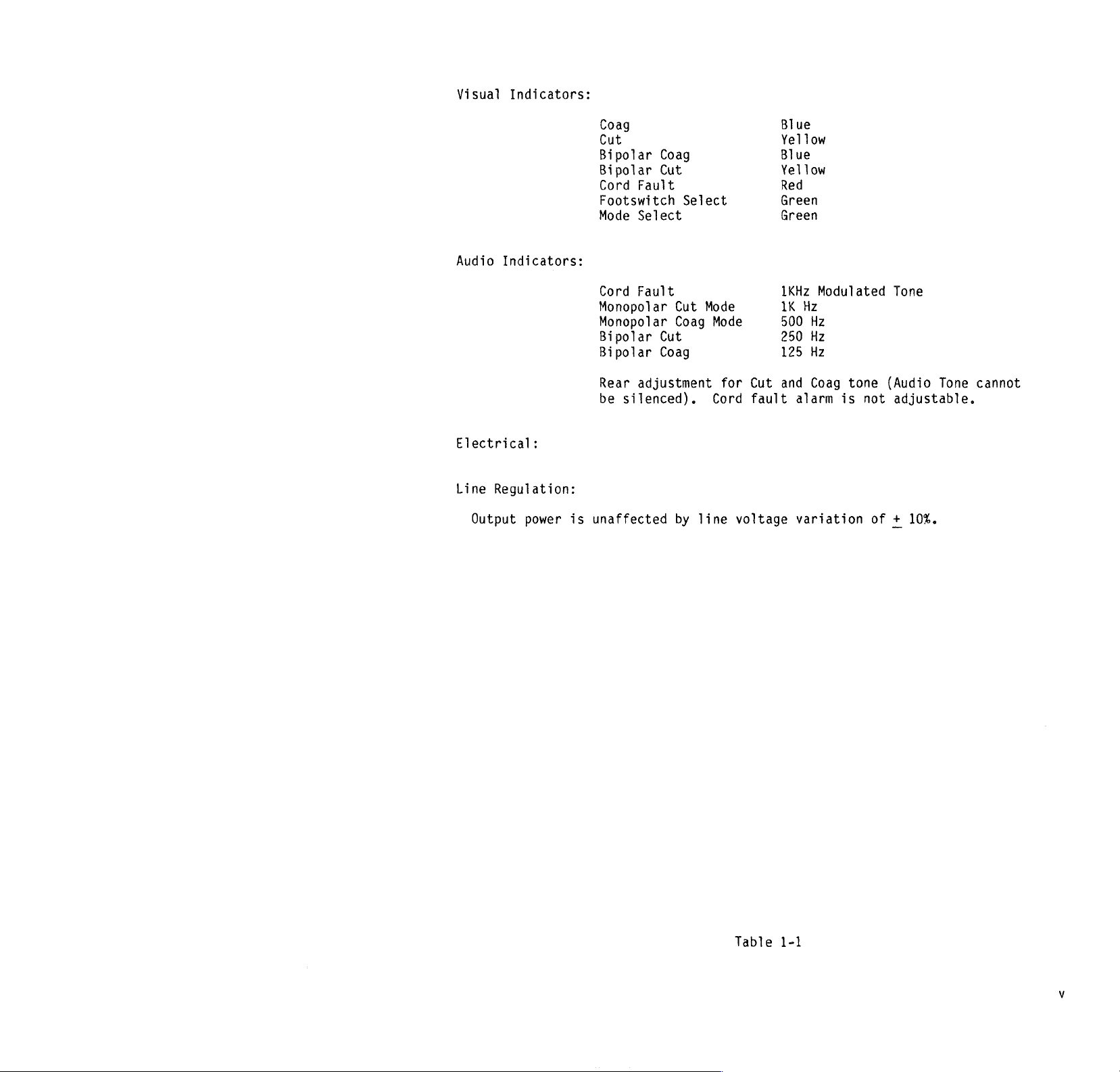
Visual
Indicators:
Audio
Electrical:
Line
Indicators:
Regulation:
Coag
Cut
Bipolar
Bipolar
Cord
Coag
Cut
Fault
Footswitch
Mode
Select
Cord
Fault
Monopolar
Monopolar
Bipolar
Bipolar
Rear
be
Cut
Coag
adjustment
silenced).
Select
Cut
Coag
Mode
Mode
for
Cord
Cut
fault
Blue
Yellow
Blue
Yellow
Red
Green
Green
1KHz
1K
Hz
500
250
125
and
alarm
Modulated
Hz
Hz
Hz
Coag
tone
is
Tone
(Audio
not
adjustable.
Tone
cannot
Output
power
is
unaffected
by
line
voltage
variation
of + 10%.
Table
1-1
Page 11
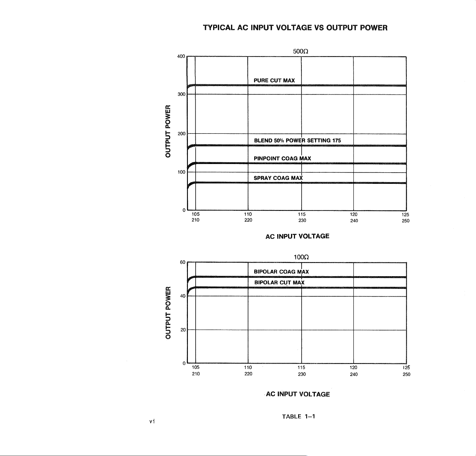
TYPICAL
AC
INPUT
VOLTAGE
VS
OUTPUT
POWER
400
300.
POWER
200
os
OUTPUT
100
105
210
500Q
PURE
CUT
MAX
BLEND
PINPOINT
SPRAY
110 115
220
50%
COAG
POWER
COAG
i
MAX
MAX
230
SETTING
175
SEE
„|
120
240
125
250
60
40
POWER
20
OUTPUT
105
210
AC
INPUT
BIPOLAR
BIPOLAR
COAG
CUT
110
220 230
'
‘AC
INPUT
VOLTAGE
100Q
|
MAX
MAX
115
VOLTAGE
120
240
125
250
vi
TABLE
1-1
Page 12
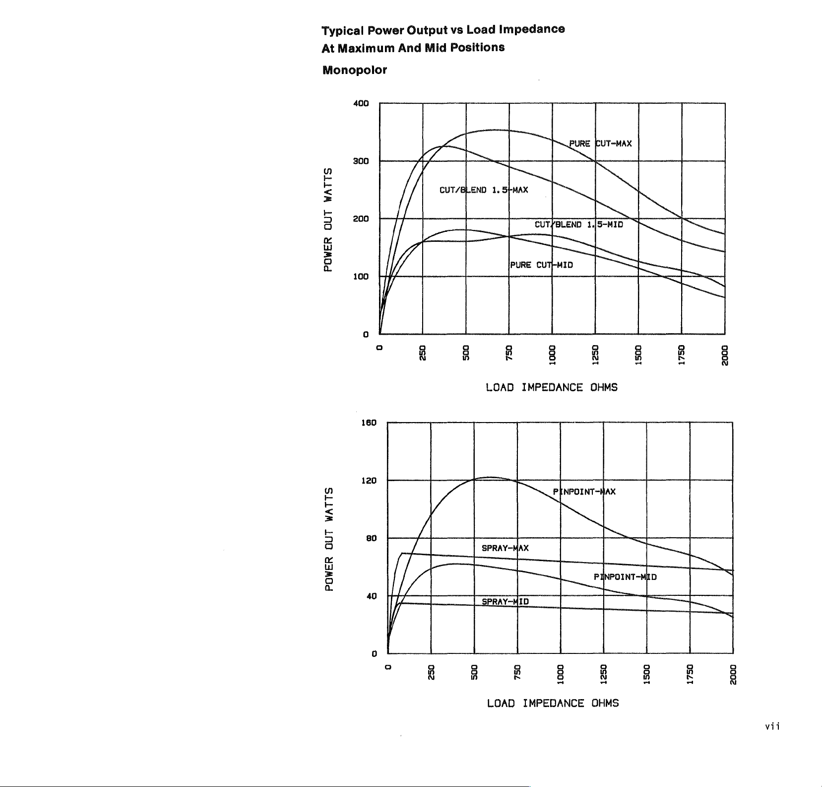
Typical
Maximum
At
Monopolor
400
Power
Output
And
Mid
Load
vs
Positions
Impedance
の
fo
E
<
5
3
300
200
100
0
o a
GS
4
7
CUT/BLEND
[oran
=
—
να
(Term
TU
1.
5+MAX
|
LOAD
OM
CUT/BLEND
© © © O
IMPEDANCE
|
1.[5-MID
OHMS
RIT
Е
기
©
fo
の
の
<
=
トー
그
O
x
=
a
160
120
κ
/
80
40
0
/
и
[777
© о о O o o o
SPRAY-MAX
|
O
PRAY-MID
LOAD
IMPEDANCE
PINeorr
OA
-
MAX
|
~
"ем
=
OHMS
P|
=
o
Page 13

Typical
At
Maximum
Bipolar
Power
60
Output
And
Mid
vs
Load
Positions
Impedance
の
~
to
<
トー
に
つ
O
x
Li
=
©
A
45
30
15
0
/
/
BIPOLAR
asi
-
COAGINID
125
COAG-MAX
A
NC
IPOLAR
BIPOLAR
250
375
LOAD
AAA]
CUT-M
CUT-MID
500
IMPEDANCE
—
ne
625
OHMS
At
750
875
1000
viii
Page 14
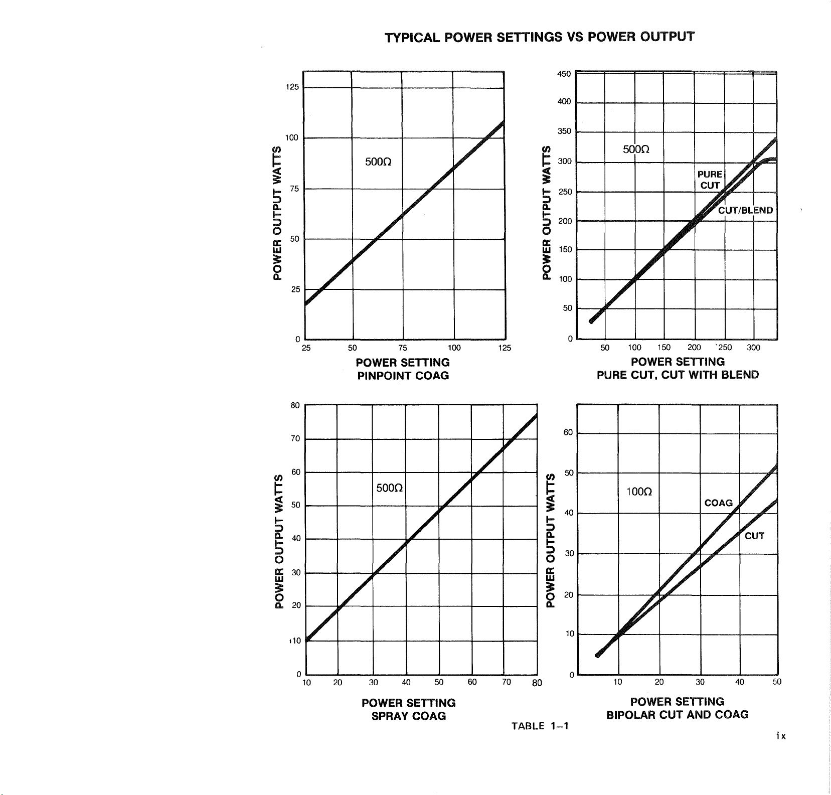
TYPICAL
POWER
SETTINGS
VS
POWER
OUTPUT
125
100
5000
WATTS
75
Y
Y
OUTPUT
5
Y
POWER
25
0 0
25
50
POWER
PINPOINT
75
SETTING
COAG
100 125
400
350
YN
E
300
=
250
f=
=>
È
-
200
o
150
Ш
=
0
9.
100
50
50
PURE
100
150
POWER
CUT,
SETTING
CUT
200
‘250
WITH
BLEND
300
80
70
60
5000
50
WATTS
40
OUTPUT
30
20
POWER
+10
0 0
10 20
30
40
A
50
^
Y
60
70
80
60
50
の
E
<
=
40
p=
E
©
e
Š
a.
30
2
10
1000
10
20 30 40
Y
COAG à À
A
ие
A
50
POWER
SPRAY
SETTING
COAG
TABLE
1-1
POWER
BIPOLAR
SETTING
CUT
AND
COAG
ix
Page 15
1500
1250
TYPICAL
POWER
SETTING
VS
OPEN
CKT
^
PEAK
VOLTAGE
1000
750
VOLTAGE
PEAK
500
250
25
4000
3500
50
100 150
POWER
SETTING
PURE
50%
CUT
BLEND
200
250
===“
300
350
3000
2500
2000
VOLTAGE
1500
PEAK
1000
500
0
10
SPRAY
COAG
25
50
POWER
PINPOINT
COAG
75
SETTING
100
500
400
5
<
„}
©
ン
<
a.
125
TABLE
300
200
100
—
0
5
10
1 一 1
BIPOLAR
COAG
BIPOLAR
20
POWER
30
SETTING
|
40
50
Page 16
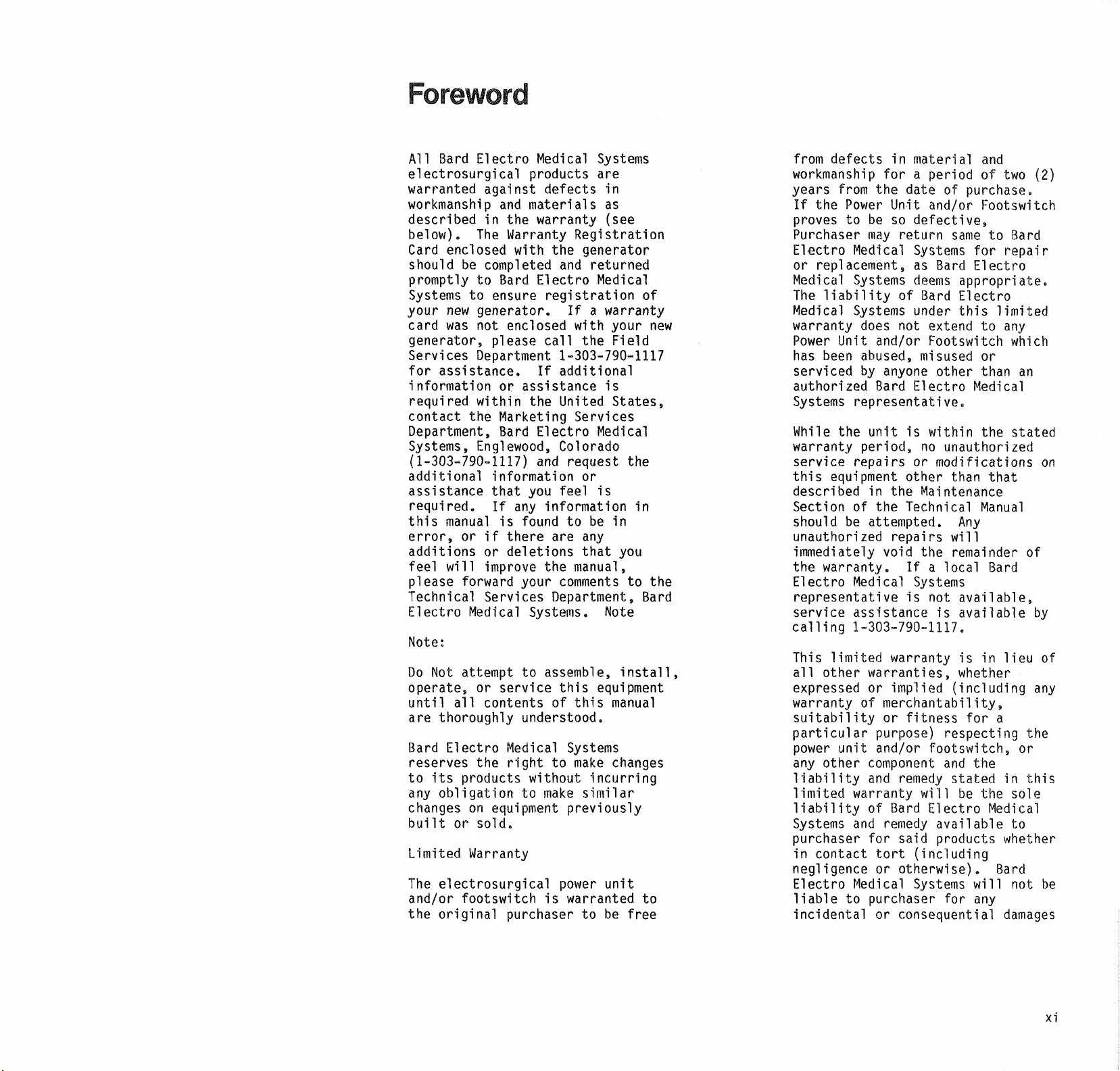
Foreword
All
Bard
Electro
electrosurgical
warranted
workmanship
described
below).
Card
should
promptly
Systems
your
card
generator,
Services
for
assistance.
information
required
contact
Department,
Systems,
(1-303-790-1117)
additional
assistance
required.
this
error,
additions
feel
please
Technical
Electro
Note:
Do
Not
operate,
until
are
thoroughly
Bard
reserves
to
its
any
obligation
changes
built
Limited
The
electrosurgical
and/or
the
original
against defects
and
in
the
The
Warranty
enclosed
be
completed
to
Bard
to
ensure
new
generator.
was
not
enclosed
please
Department
or
within
the
Marketing
Bard
Englewood,
information
that
If
manual
will
all
Electro
or
is
or
if
there
or
deletions
improve
forward
Services
Medical
attempt
or
service
contents
Medical
the
right
products
on
equipment
sold.
Warranty
footswitch
purchaser
Medical
products
materials
warranty
Registration
with
the
and
Electro
registration
If a warranty
with
call
1-303-790-1117
If
additional
assistance
the
United
Services
Electro
Colorado
and
request
you
feel
any
information
found
your
to
understood.
to
to be
are
the
manual,
comments
Department,
Systems.
assemble,
this
of
this
Systems
to
make
without
make
previously
power
is
warranted
Systems
are
in
as
(see
generator
returned
Medical
your
the
Field
is
States,
Medical
the
or
is
in
in
any
that
you
to
Note
install,
equipment
manual
changes
incurring
similar
unit
to be
free
of
new
the
Bard
to
from
defects
workmanship
years
If
proves
Purchaser
Electro
or
Medical
The
Medical
warranty
Power
has
serviced
authorized
Systems
While
warranty
service
this
described
Section
should
unauthorized
immediately
the
Electro
representative
service
calling
This
all
expressed
warranty
suitability
particular
power
any
liability
limited
liability
Systems
purchaser
in
negligence
Electro
liable
incidental
from
the
the
Power
to
be so
may
Medical
replacement,
Systems
liability
Systems
does
Unit
and/or
been
abused,
by
Bard
representative.
the
unit
period,
repairs
equipment
in
of
the
be
attempted.
warranty.
Medical
assistance
1-303-790-1117.
limited
other
other
contact
warranties,
or
of
unit
component
and
warranty
of
and
for
Medical
to
purchaser
purpose)
and/or
tort
or
or
in
material
for a period
date
Unit
and/or
defective,
return
Systems
as
Bard
deems
of
Bard
under
not
extend
Footswitch
misused
anyone
the
repairs
void
warranty
implied
merchantability,
or
Bard
remedy
other
Electro
is
within
no
or
modifications
other
Maintenance
Technical
the
If a local
Systems
is
not
is
fitness
footswitch,
remedy
will
Electro
available
said
products
(including
otherwise).
Systems
consequential
and
of
of
purchase.
Footswitch
same
for
Electro
appropriate.
Electro
this
to
or
than
Medical
the
unauthorized
than
Manual
Any
will
remainder
available,
available
is in
whether
(including
for
respecting
and
the
stated
be
the
will
for
any
two
to
Bard
repair
limited
any
which
an
stated
that
of
Bard
lieu
a
the
or
in
this
sole
Medical
to
whether
Bard
not
damages
(2)
on
by
of
any
be
xi
Page 17
arising
out
handling,
servicing
same.
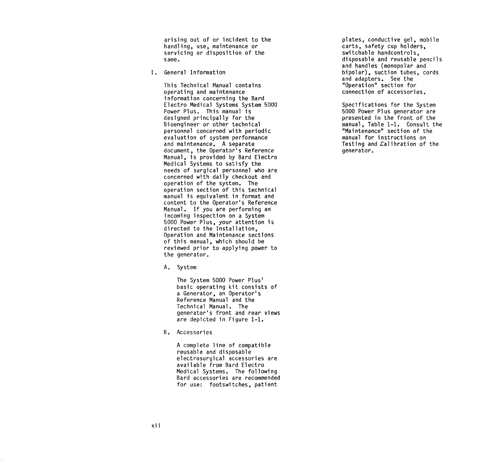
General
This
Information
Technical
operating
information
Electro
Power
Medical
Plus.
designed
Bioengineer
personnel
evaluation
and
maintenance.
document,
Manual,
Medical
needs
concerned
operation
operation
manual
content
Manual.
incoming
5000
directed
Operation
of
reviewed
the
is
Systems
of
is
to
Power
to
this
manual,
generator.
of
or
incident
use,
maintenance
or
disposition
Manual
and
maintenance
concerning
Systems
This
manual
principally
or
other
concerned
of
system
A
the
Operator's
provided
to
surgical
with
of
section
daily
the
personnel
system.
of
equivalent
the
Operator's
If
you
are
inspection
Plus,
and
your
the
Installation,
Maintenance
which
prior
to
applying
to
or
of
the
contains
the
Bard
System
is
for
the
technical
with
periodic
performance
Separate
Reference
by
Bard
Electro
satisfy
checkout
this
in
performing
on a System
the
who
The
technical
format
Reference
attention
sections
should
power
the
and
be
5000
are
and
an
is
to
plates,
carts,
switchable
disposable
and
bipolar),
and
conductive
safety
handcontrols,
and
handles
suction
adapters.
"Operation"
connection
of
Specifications
5000
Power
presented
manual,
Plus
in
Table
"Maintenance"
manual
Testing
generator.
for
instructions
and
Calibration
gel,
cup
holders,
reusable
(monopolar
tubes,
See
the
section
accessories.
the
1-1.
section
for
for
the
generator
front
Consult
mobile
pencils
and
cords
System
of
of
the
on
of
are
the
the
the
xii
A.
System
The
System
basic
a
Generator,
Reference
Technical
generator's
are
depicted
B.
Accessories
A
complete
reusable
electrosurgical
available
Medical
Bard
for
use:
5000
operating
an
Manual
Manual.
front
in
line
and
disposable
from Bard
Systems.
accessories
footswitches,
Power
kit
Plus'
consists
Operator's
and
the
The
and
rear
Figure
of
1-1,
compatible
accessories
Electro
The
following
are
recommended
patient
of
views
are
Page 18
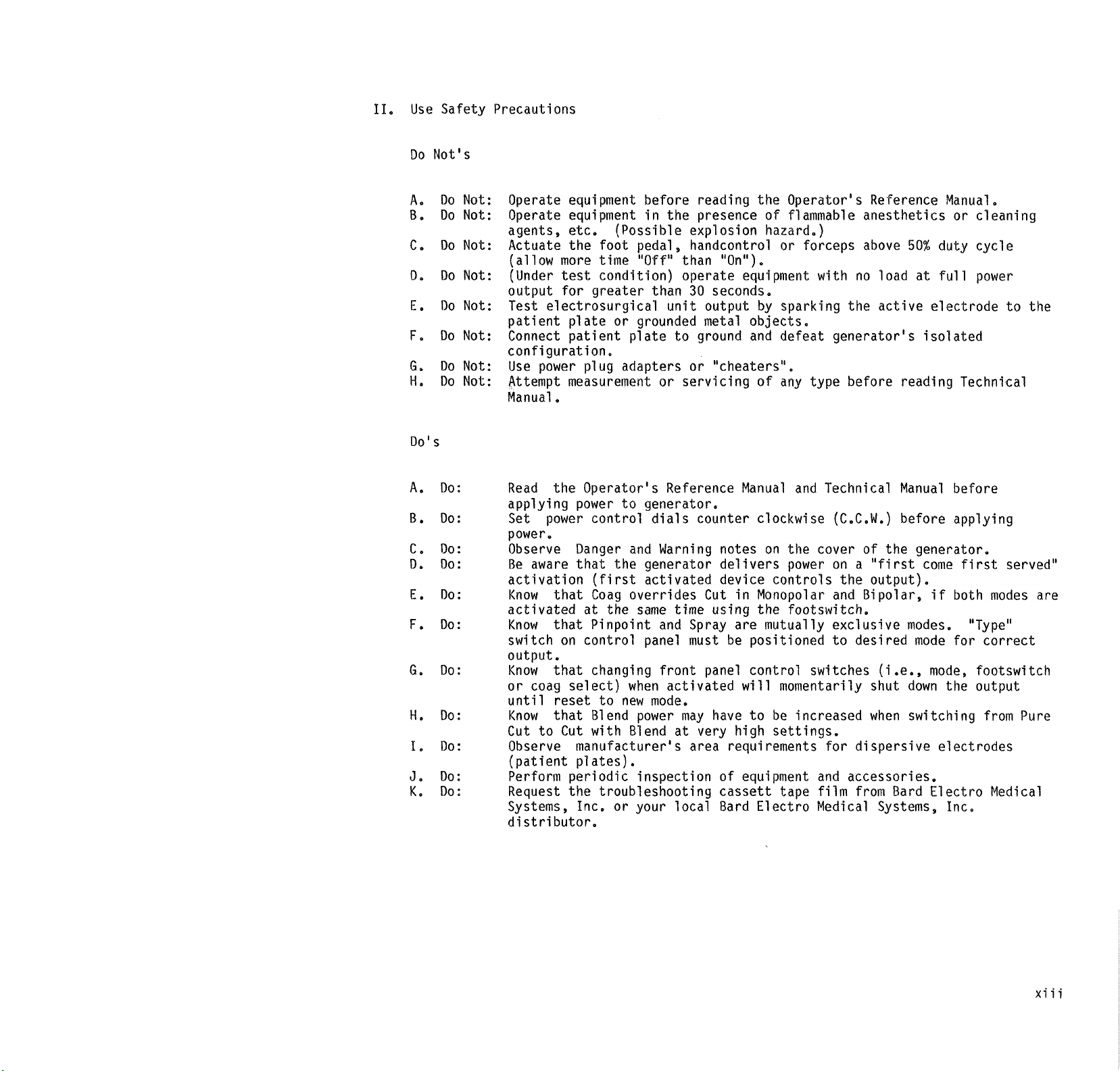
II.
Use
Do
Safety
Not's
Precautions
A. Do
B.
Do
C. Do
D.
Do
E.
Do
Е.
Do
G.
Do
H.
Do
Do's
A.
Do:
B.
Do:
C.
Do:
D.
Do:
E.
Do:
F.
Do:
G.
Do:
H.
Do:
I.
Do:
Je
Do:
K.
Do:
Not:
Not:
Not:
Not:
Not:
Not:
Not:
Not:
Operate
Operate
agents,
Actuate
(allow
(Under
output
Test
patient
Connect
configuration.
Use
Attempt
Manual.
Read
applying
Set
power.
Observe
Be
activation
Know that
activated
Know
switch
output.
Know
or
until
Know
Cut
Observe
(patient
Perform
Request
Systems,
distributor.
equipment
equipment
etc.
the
more
test
for
greater
electrosurgical
plate
patient
power
aware
coag
to
plug
measurement
the
Operator's
power
power
control
Danger
that
(first
Coag
at
that
Pinpoint
on
control
that
changing
select)
reset
that
Blend
Cut
with
manufacturer's
plates).
periodic
the
Inc.
before
in
the
(Possible
foot
pedal,
time
“Off"
condition)
or
grounded
plate
adapters
to
generator.
and
the
generator
activated
overrides
the
same
panel
when
to
new
power
Blend
inspection
troubleshooting
or
your
explosion
handcontrol
than
operate
than
30
unit
to
or
or
servicing
Reference
dials
Warning
time
and
Spray
must
front
activated
mode.
may
at
area
local
reading
presence
"On").
equipment
seconds.
output
metal
ground
counter
objects.
and
"cheaters".
Manual
notes
delivers
device
Cut
in
using
are
be
positioned
panel
very
control
will
have
to
high
requirements
of
equipment
cassett
Bard
the
Operator's
of
flammable
hazard.)
or
forceps
with
by
sparking
defeat
of
any
type
and
clockwise
on
the
cover
power
controls
Monopolar
the
footswitch.
mutually
switches
momentarily
be
increased
settings.
and
tape film from Bard
Electro
Medical
anesthetics
above
no
the
generator's
before
Technical
(C.C.W.)
of
on a “first
the
and
Bipolar,
exclusive
to
desired
for
dispersive
accessories,
Reference
50%
load
at
active
isolated
reading
Manual
before
the
generator.
come
output).
modes.
mode
(i.e.,
shut
down
when
switching
Systems,
Manual.
or
cleaning
duty
cycle
full
power
electrode
Technical
before
applying
first
if
both
"Type"
for
correct
mode,
Electro
footswitch
the
output
from
electrodes
Inc.
to
the
served"
modes
Pure
Medical
are
xiii
Page 19
|
的
|
i
FOGTSWITCH
i
|
MONEDA
|
NE
AA
i
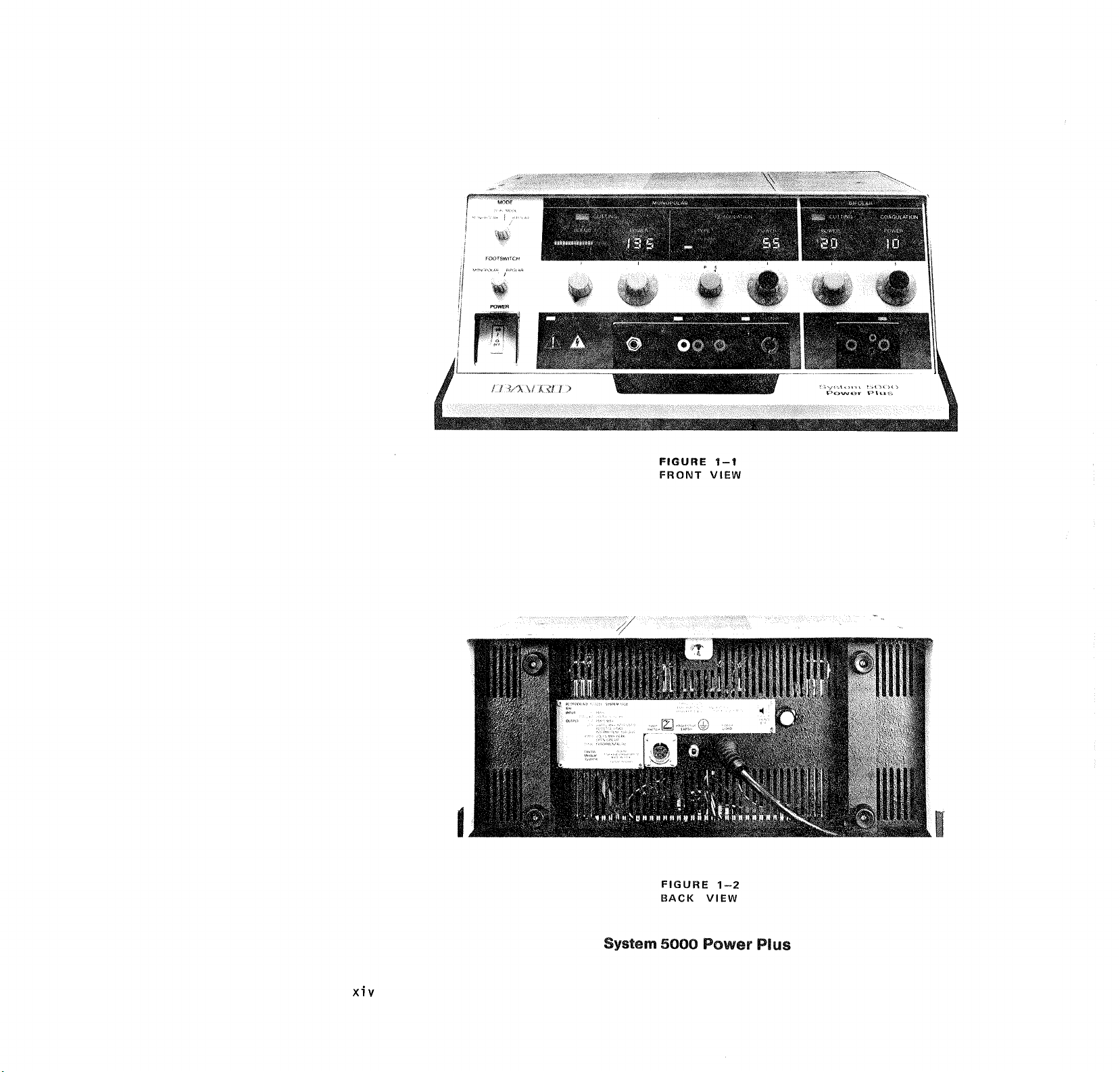
FIGURE
FRONT
1-1
VIEW
Sigean
Power
Οσον
haa
System
FIGURE
BACK
5000
1-2
VIEW
Power
Plus
Page 20
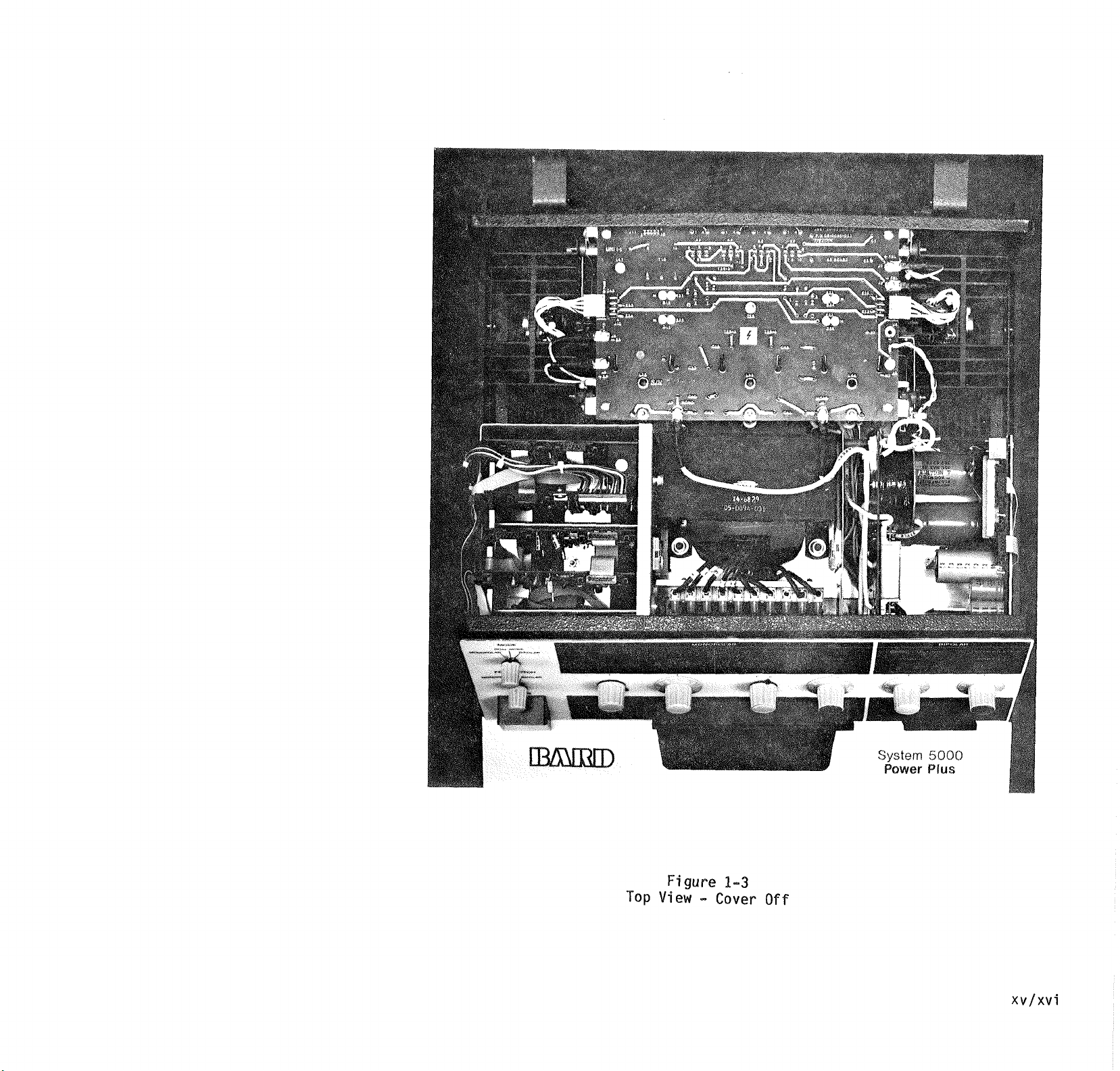
|
Top
Figure
View
-
1-3
Cover
Off
System
Power
5000
Plus
xv/xvi
Page 21

DESCRIPTION
Page 22
Description
General
This
section
concerning
and
Functional
System
surgical
generator
unit
power
conventional
output
requirements
surgery.
The
incorporates
state-of-the-Art
devices.
easy
Sub-assemblies.
power
well
output
Functional
selector
the
when
activates.
The
generator
(patient
chassis
designed
"first
only
activated
monitor
5000
that
to
power
System
removal
controls
as
receptacles.
desired
the
System
come
one
dispersive
plate)
in
malfunction.
the
integrity
event
different
are the
distinguish
cutting
or
bipolar)
The
audio
silenced
event
of
circuits
personnel
of
the
generator,
contains
the
Power
Generator.
is
an
provides
meet
surgery
to
of
5000
.the
Modular
and
the
mode
lamps
switches
modes
cord
5000
is
an
return
ground).
with
first
accessory
at a time. A cord
circuit
electrode
of a disconnection
frequencies
mode
lights)
the
and
coagulation
modes
circuits
completely,
an
accidental
will
of
generator
information
general
operation
extremely
the
meet
more
Power
latest
electronic
replacement
The
are
indicators
illuminate
fault
Power
isolated
Not
discrete
senses
Description
Plus
electro-
The
monopolar
requirements
and
the
delicate
Plus
design
front
color
In
addition,
are
positioned
of
operation,
monitor
Plus
referenced
The
generator
output,
served"
will
the
(patient
sounding
Mode
tones
are
to
activations
of
operation.
cannot
so
that
activation
the
audio
emit a tone
activation.
of
the
5000
versatile
output
of
Bipolar
enables
of
panel
coded,
system
meaning
be
an
of
used
as
and
when
or
to
is
fault
alarm
or
(as
clearly
of
the
(monopolar
be
in
the
alerting
to
Modes
The
System
generator
basic
operation
modes
bipolar
А.
Monopolar
1.
2.
3.
4,
B.
Bipolar
1,
5000
Power
provides
of
and
four
monopolar
two
(2)
operation.
Pure
Cutting:
incision
hemostasis.
continuous
sinusoid.
load.)
Blend:
with
a
variable
modulated
(500
from
Period
Pin
Provides
(dessication).
fixed
modulated
sinusoid
(500
duration
50usec.
Spray
where
sparking
required.
modulated
sinusoid
period
Bipolar
vides
power
accessories.
pulse
Sinusoid
Pulse
Period
with
500KHz,
(Independent
Provides
hemostasis.
duration
500KHz,
ohm
load)
47 + 2usec
50usec.
Point
Coagulation:
hemostasis
duration
500KHz,
(open
ohm
load),
7usec.
Coagulation:
fulguration,
to
Generates
500KHz
(open
32usec.
Coagulation:
reduced
to
bipolar
modulated
(125
duration
50usec。
Plus
(4)
modes
Provides
minimal
Generates
cutting
Generates
sinusoid:
variable
to
14
Generates
pulse
damped
circuit)
Pulse
Period
i.e.,
tissue
is
damped
circuit)
coagulation
Generates
500KHz
ohm
load).
7usec.
of
an
a
of
pulse
usec.
Used
pulse
Pro-
1-1
Page 23
II.
Functional
A
of
control,
connectors
page
The
mode,
selectors
described
A.
2.
Bipolar
cutting
accessories.
continuous
(Independent
complete
each
front
indicator
"Operations!
3-12.
function
footswitch,
and
as
Mode
Switch
1.
Monopolar
а.
b.
Cutting:
power
500KHz
description
and
rear
and
is
shown
in
section
of
the
front
pin
blend
control
follows:
Position
Monopolar
displays
Cord
fault
illuminates
sound
warning
circuit
tone
dispersive
(patient
connected
dispersive
Monopolar
flows
isolated
selected
active
through
accessory,
patient,
the
dispersive
Discrete
monopolar
accessory
provide
accompanying
receptacle.
Pure
pin
modes
through
receptacles
the
generator
power
cutting,
point
are
Provides
to
bipolar
Generates
sinusoid.
of
load).
and
purpose
panel
accessory
the
of
this
manual
panel
point/spray
are
LED
digital
illuminate.
lamp
and
the
emits
until
electrode
plate)
to
is
the
receptacle.
RF
current
an
loop
from
monopolar
active
through
and
returns
via
the
electrode.
output:
first
activated
and
mode
to
its
output
blend,
and
spray
available
a
a
a
the
the
to
will
2.
subject
selector
positions.
Method
modes
footswitch
position.
Bipolar
Bipolar
display
Cord
warning
(Dispersive
not
bipolar
Bipolar
Ce
restricted
grasped
bipolar
The
flows
isolated
generator's
active
the
forceps
patient
by
the
return
output
Discrete
activated
accessory
power
receptacles.
Both
and
are
of
on
selector
Dual
Mode
ae
Both
bipolar
displays
Cord
b.
illuminates
sound
to
mode
switch
of
activating
depends
on
selector
Position
LED
digital
illuminates.
fault
tone
lamp
turn
electrode
required
for
operation.)
RF
current
to
tissue
between
forceps'
bipolar
through
active
the
generator
to
bipolar cutting
coagulation
available.
activating
the
Position
monopolar
fault
circuit
RF
an
loop
from
bipolar
receptacle
accessory
jaw
through
tissue
forceps,
via
forcep
jaw
receptacle.
output:
bipolar
will
the
bipolar
depends
footswitch
position.
LED
digital
illuminate.
lamp
and
emits
the
and
Off.
is
the
jaws.
current
the
to
the
grasped
back
the
and
first
provide
modes
Method
and
the
a
to
1-2
Page 24
B.
c.
d.
e.
Footswitch
Provides
1.
switch
either
bipolar
Illuminates
functional
active
indicating
accessories
or
footcontrolled)
warning
dispersive
(patient
connected
dispersive
(Monopolar
available,
return
Monopolar
RF
available.
current
cal
for
switch
lar
identical
cribed
mode
Discrete
accessory
(whether
monopolar
cutting
ing),
footswitch,
or
forceps, provides
power
ing
tone
until
electrode
plate)
to
the
receptacie.
RF
current
hence,
path
required.)
and
bipolar
current
are
Monopolar
flow
is
to
that
described
the
monopolar
position.
current
switch
for
flow
to
that
the
position.
output:
activated
it
be
or
bipolar
or
coagulat-
activated
handcontrol
handswitchable
to
its
accompany-
active output
receptacle.
Any
of
the
six
modes
pure
pin
spray
bipolar
bipolar
can
switch
of
operation,
cutting,
point
coagulation,
coagulation,
cutting
coagulation,
be
used
selection.
Selector
choice
activation
the
monopolar
output
receptacles.
the
lamps
output
receptacles,
which
(handcontrolled
blend,
with
of
for
green
above
type
a
is
both
identi-
mode
Bipo-
is
des-
bipolar
first
by
the
(6)
or
proper
foot-
or
the
of
are
Blend
C.
1.
Coagulation
1.
available
and
delivery
Control
When
in
the
clockwise
(CCW),
the
To
of
blend
(CW)
the
pure
activate
operation,
control
out
position
click).
rotation.
control
of
will
illuminate
graph
control
controls
width
The
blend
above
knob.
the
in
more
bar
hemostasis
cutting
cutting
adjusts
blend
control
effect.
power
the
output
adjusts
width,
Type
When
positioned
point
type
available.
lamp
marked
the P/S
will
When
spray
selector
illuminate.
positioned
type
available.
lamp
marked
P/S
selector
illuminate.
The
pin
point/spray
coagulation
no
effect
cutting,
modes.
Switch
for
activation
of
power.
fully
detent
counter-
position
generator
cutting
the
mode,
blend
rotate
clockwise
of
its
detent
(should
Further
the
hear
clockwise
blend
progressively
the
LED
the
blend
This
variable
the
blend
illuminated
graph,
effect
the
and
The
control
power
and
of
the
the
Selector
to
coagulation
The
green
pinpoint
switch
to
coagulation
The
green
spray above
switch
positions
in
the
pure
blend
or
bipolar
design
is
mode
the
a
bar
action
pulse
mode.
the
more
less
the
blend
pulse
"P",
mode
above
"S",
mode
will
have
in
pin
is
is
the
1-3
Page 25
separates
4,
When
switching
type
selector
digital
change.
Safety
1.
Features
Discrete
active
time,
2.
Cord
Fault:
personnel
connection
sive
electrode
plate)
output
fault
action
monopolar
cutting,
and
spray).
3.
Coag
Override:
circuits
ulation
activated,
al
simultaneous
of
the
The
footswitch
designed
lock-out
4,
Isolated:
current
generator
persive
Operational
1.
In
the
of
functional
the
differences
mode
will
There
in
selector
positions,
indicators,
receptacles
circuit
Reiteration
the
circuits.
coagulation
(P/S),
readout
will
Output:
accessory
at
Alerts
in
case
of
the
(patient
and
also
inhibits
power
is
occurs
until
corrected.
in
all
modes
blend,
(pure
pin
Mode
permits
circuits
should
footswitch
with
feature.
only
to be
activation
is
coag
Return
restricted
active
and
electrode
Mode
Considerations
following
discussion
modes,
of
be
explained.
are
many
similarities
switch
controls,
output
and
overall
configurations.
will
LED
Only
one
any
of a dis-
disper-
the
This
four
point
logic
coag-
accident-
occur.
also
override
RF
to
dis-
loop.
only
each
be
III.
repeated
considered
Power
will
the
the
Table
Color
yellow;
active,
Tamps
While
Plus
with
it is
continuous
Activation
in
should
to
by
or
Low
triggered
modes,
are
coagulation
(Coagulation
require
applied
amplifiers
desired
peak
Dispersive
(patient
used
modes.
Operational
A.
Monopolar
Pure
1.
Blend
detent
request
power
only when
delivered
vary
power
front
1-1,
code
coagulation,
red
are
the
generator
wide
not
the
monopolar
generally
one
minute
an
"off"
longer
voltage
High
triggered
higher
to
RF
voltage.)
plates)
for
all
Modes
Cutting
control
(full
for
by
means
significant.
to
loads
as
described
curves
of
for
the
cutting,
and
functional
shown
manual
green.
System
safety
intended
5000
is
designed
margins,
for
operation.
of
an
accessory
mode
be
"on"
followed
time
of
duration.
triacs
in
the
are
cutting
voltage
in
the
modes.
type
signals
peak
the
RF
output
to
obtain
output
peak-to-
electrodes
must
monopolar
Operation:
must
be
CCW).
pure
cutting
of
the
in
in
and
blue;
Power
limited
equal
triacs
voltage
the
be
in
A
Page 26
handcontrol
results
action:
The
ae
emits a tone
The
b.
monopolar
illuminates.
The
triggers
variable
voltage
RF
voltage
in
ing
cutting
dial.
can
0-350
The
generates a continuous
500KHz
This
the
driver
vates a fullwave
bridge
is
ventional
are
determining
The
further
this
livered
lar
A5T29.
then
eliminate
low
energy.
then
selected
output
balance
A12T1
voltage
controlled
logic
or
footswitch
in
the
following
cut
sound
front
low
amplifiers.
pure
the
be
RF
RF
configured
driven
panel,
lamp
voltage
and
20-125
to
the
is
controlled
cut
by
monopolar
power
The
output
controlled
watts.
logic
squarewave.
squarewave
driver,
amplifier
amplifier
relays
by
circuits.
RF
signal
amplified
amplifier
to
the
output
filtered
and
routed
transformer,
The
signal
undesirable
high
RF
power
to
monopolar
receptacle
transformer
by
means
relays
by
circuits.
circuit
of
1KHz。
yellow
triac
provides
DC
output
This
adjust-
control
power
from
circuit
drives
The
acti-
type
which
by
con-
that
the
mode
is
by
and
de-
monopo-
is
to
frequency
is
the
via
of
high
the
mode
a
Blend
2.
Operationally,
(cutting
is
nearly
cutting.
must
enter
further
rotation
hemostasis
the
cutting
be
monitored
graph.
A
request
power
same
cutting:
handcontrol。
circuit,
lamp,
are
all
in
the
output power
from
The
RF
different
a
"pulsed"
generated
of a continuous
The
RF
bridge
configuration,
transformer,
balanced
voltage
receptacles
the
pure
Additional
front
are
required
blend
circuit
covered
Theory
Pin
3.
Point
Operation
The
coagulation
selector
Operation
with
identical
The
be
out
the
mode
clockwise
increases
and
for
is
acquired
means
0-230
as
footswitch
mode
and
low
the
blend
watts.
logic
in
waveform
at
driver,
amplifier
transformer
relays
cutting
circuits
panel
waveform.
analysis
in
Section
of
Operation.
Coagulation
switch
blend
hemostasis)
blend
of
detent
and
any
(CW)
the
decreases
effect,
on
the LED
blend
by
was
pure
The
cut
indicator
voltage
same.
mode,
is
circuit
blend,
500KHz
filter,
are
and
to
However,
the
controlled
waveform.
fullwave
output
and
output
common
mode,
RF
create
(Detailed
will
V,
"type"
must
to
pure
control
to
as
can
bar
cutting
the
or
sound
triac
is
in
that
is
instead
high
to
in
the
logic
the
be
be
in
1-5
Page 27
"p"
(pinpoint). A request
for
pinpoint
power
control,
by
handswitchable
forceps
following
a.
The
coagulation
means
footswitch
results
actions.
coag
sound
of
monopolar
in
emits a tone
b.
The
front
monopolar
panel,
lamp
illuminates.
Co
The
high
voltage
triggers
variable
voltage
and
20-200
to
the
amplifiers.
voltage
in
by
monopolar
power
The
controlled
watts,
d.
The
is
pinpoint
adjusting
control
output
RF
logic
controlled
coagulation
coagulation
power
from
generates a "pulsed"
500KHz
pulse
busec
50usec
From
the
forward,
coagulation
same
RF
configuration
output
used
for
and
blend
Spray
squarewave.
width
at a period
。
RF
logic
pinpoint
utilizes
driver,
and
circuitry
the
pure
modes.
Coagulation
is
amplifier
hand-
or
the
circuit
of
500Hz.
blue
triac
provides
DC
RF
This
the
dial.
can
0-130
circuit
fixed
of
circuit
the
monopolar
as
was
cutting
Operation
a
be
Its
at
B.
c.
d.
Bipolar
1.
Bipolar
Operation
pulse
32usec
The
bridge
is
stacked,
duration
period.
previous
type
now
converted
single-ended
amplifier
by
means
of
conventional
which
also
single-ended
output
spray
output
A2T2.
output
to
(fulgeration)
transformer,
This
configuration
generates
peak-to-peak
produce
the
(sparking
hemostasis
is
then
routed
the
balance
to
the
selected
monopolar
via
the
high
fulguration
The
output
spray
watts
power
display
the
ranges
as
indicated
readout
controlled
monopolar
cogulation
control
Power
changes
type
dial.
readout
as
selector
Coagulation
at
a
fullwave
amplifier
to
a
configuration
logic
and
relays
transfer
the
amplifier
the
monopolar
type
RF
the
necessary
voltage
to
fulguration
to
tissue)
effect
that
through
transformer
receptacle
voltage
relay.
power
from
in
0-75
on
digital
by
power
Note:
display
coagulation
switched.
Spray
from
pinpoint
in
the
a.
The
selector
to
b.
The
generates
Squarewaves
coagulation
coagulation
following
coagulation
is
"S"
(spray).
RF
logic
"pulsed"
differs
ways:
"type"
positioned
circuit
of
1.8usec
The
mode
selector
must
be
positioned
either
mode.
bipolar
Dual
mode
or
will
require a dispersive
electrode.
A
request
coagulation
means
of
for
is
the
bipolar
obtained
footswitch
switch
to
dual
by
or
Page 28
handswitching
forceps
following
a.
The
resulting
actions:
coag
sound
emits a tone
b.
The
front
blue
coagulation
illuminates.
c.
The
high
voltage
d.
triggers
point
The
power
from
bipolar
power
The
as
and
bipolar
can
0-50
coagulation
control
RF
logic
watts
generate a "pulsed”
KHz
squarewave.
pulse width
and
period
The
RF
driver
output
the
as
same
in
pinpoint
amplifier
configuration
cogulation.
circuits
set
conventional
connect
transformer,
The
routed
bipolar
bipolar
the
signal
through
filter
output
receptacles.
bipolar
in
circuit
at
panel
in
the
spray
output
be
adjusted
dial.
circuits
is
6usec
is
50usec,
and
The
up
relays
bipolar
A5T10.
then
the
to
the
125Hz.
bipolar
lamp
triac
pin-
modes.
by
the
500
Its
are
logic
the
to
is
the
watts
cutting
by
the
power
dial.
d.
The
RF
logic
generates a "continu-
ous"
500KHz
The
amplifier
and
output
same
for
bipolar
it
was for
coagulation.
squarewave.
configuration
circuitry
bipolar
bipolar
control
circuit
is
cutting
the
as
Bipolar
The
bipolar
differs
lation
ways:
a.
The
a
tone
b.
The
yellow
illuminates.
Co
The
triggers
and
bipolar
adjusted
Cutting
from
in
the
cutting
of
front
cutting
low
blend
Operation
cutting
bipolar
following
sound
250Hz.
panel
voltage
as
in
modes.
output
from
mdoe
coagu-
emits
bipolar
lamp
triac
cutting
The
can
0-50
be
1-7/1-8
Page 29

INSTALLATION
Page 30
Installation
Unpacking
I.
Upon
Power
carton,
exterior
visible
evident,
representative
while
examine
Note
Treat
carton
5000
medical
handling
The
System
packed
generator
6-2)
receipt
Plus
carefully
of
damage.
have
you
the
the
with
Power
instrument,
can
in
©
of
the
in
its
the
carton
the
remain
open
the
contents.
contents
care.
Plus
is a durable
damage
5000
Power
one
carton,
as
follows:
System
shipping
examine
for
If
damage
carrier's
with
carton
of
this
The
System
but
it.
Plus
unpack
(See
5000
the
is
you
and
rough
is
Figure
the
II.
warranty.
Note
Record
model
These
referred
and
numbers
numbers
regarding
Generator.
Assembly
The
System
no
additional
use.
5000
When
Power
generator
specially
any
stable
should
the
as
bottom
be
generator
Not
to
or
retain
of
should
to
in
any
the
5000
5000
assembly
setting
Plus
should
designed
cart
exercised
on a cart
obstruct
rear
of
the
serial
the
generator.
always
correspondence
Electrosurgical
Power
Plus
prior
up
the
for
use,
the
be
placed
Mobile
or
table.
when
placing
or
the
vents
the
generator.
and
be
requires
to
System
on
the
Cart
or
Caution
table
on
so
the
A.
Open
the
B.
Remove
C.
Remove
Reference
Technical
D.
Lift
E.
Inspect
equipment
or
missing
the
determine
sustained
If
so,
and
report
settlement
Save
the
material
tional.
must
be
carton
from
shipping
carton
unit
carefully,
by
negligence
the
carton
System
5000
the
foam
the
Operator's
Manual
Manual.
out
the
the
for
components.
equipment
if
during
contact
advise
can
them
be
determined.
packing
until
If
for any
returned,
will
help
damage.
is
not
available,
can
containing
Power
packing.
and
generator.
unpackaged
visible
is
damaged,
the
damage
shipment,
the
carrier
so
that
made
and
carton
the
unit
reason
the
original
protect
If
since
void
damage
the
Plus,
the
damage
If
was
a
and
is
opera-
the
the
the
pack
unit
unit
the
caused
Cautions
This
generator
Grounded
connecting
power
chassis.
possibility
that
electrical
cable
could
at
the
This
result
shorts
the
to
of
cabinet,
The
Users'
insure
power
the
generator.
Generators
Responsibility
proper
outlets
are
with a standard
prong
requirement
connector,
standards
Grounding.
Note:
Refer
this
to
the
manual
Operation
or
was
properly
factory
ground
the
generator
reduces
electrical
from
to
the
grounding
that
provide
normally
hospital
which
the
Operator's
by
wire
in
the
shocks
internal
generator
is
of
the
power
shipped
grade
meets
for
Safe
section
the
to
AC
to
3
of
Page 31

Reference
operating
Manual
instructions.
for
detailed
IT.
I
IV.
Environmental
Danger
Use
of
this
combustible,
atmospheres
explosion
possible
Unit
hazard
spark
should
temperatures
to
100°F)
humidity
Note:
Avoid
temperatures
and
range
storing
(140°F).
Operational
A.
Refer
Plus
or
manual
pertaining
adjustments
functions,
to
Operator's
the
Operation
for
Requirements
device
or
is
be
from
exceeding
Set-Up
the
in
flammable,
oxidizing
not
recommended.
may
exist
emissions.
operated
10°C
within a relative
of 0 to
the
unit
System
instructions
to
preliminary
and
at
to
38°C
97%.
at
60°C
5000
Reference
section
control
due
air
Power
manual
of
An
to
(50°
this
2-2
B.
Place
generator
surface
as
the
the
not
bottom
System
on a clean,
and
allow ample
to
obstruct
of
5000
the
Power
flat
room
the
vents
generator.
Plus
so
on
Page 32

OPERATION
Page 33

Bard
Electro
Medical
Systems
System
Power
Operator’s
Reference
FOOTSWITCH
BELA
A
rize
5000
Plus
Manual
BLEND
ls
1
i
i
CÆAGULATIOR.
BANRID
Page 34

System
5000
Electrosurgical
Preface
The
System
for
use
functions
and
convenience.
The
System
spray.
areas.
tissues
that
allows
hemostasis.
For
your
calibrated
unit
has
isolated
See
the
5000
in
the
modern
to
satisfy
5000
Pinpoint
Spray
over
coagulation
coagulation
broad
you
to
convenience,
in
watts
totally
separate
R.F.
output.
contents
Power
Generator
Power
operating
all
of
your
Power
provides
surface
set the
with
of
the
large,
bipolar
this
Operator's
exact
Plus
Plus
is a multi-purpose
room.
surgical
Plus
offers
provides
areas.
power
precise
greater
This
power
output
illuminated
controls,
Manual
It
features
demands
two
levels
control
control
unit
also
desired
of
the
digital
discrete
for
electrosurgical
both
monopolar
with
safety,
of
coagulation,
of
bleeding
of
bleeding
offers
infinitely
for
pure
cut
System
displays.
further
5000
output,
details.
flexibility,
in
in
highly
variable
or
cutting
Power
For
your
cord
fault
generator
and
bipolar
reliability
pinpoint
localized
vascular
blend
with
Plus
safety
this
alarm
and
is
and
Page 35

Top
Cover
Instructions
a
<
고
©
0
る
=
e
3
o
a
m
に
о
=
1
<
5
a
Connections
Dispersive
Connect
receplacle.
Footswitch
Connect
(Not
Active
HANDCONTROL
Pencil — 3-pin
Forceps — 2-pin
FOOTCONTROL
Pencil
Forceps
Endoscopic
Single-use
Dispersive
Footswitch
Connect
{Not
Active
Dual
Handcontrol
Footcontrol
Dispersive
Connections
Electrode:
dispersive
electrode
footswitch
cord
required
when
using
Accessories
receptacl
monopotar
monopolar
receptacie
cord
accessories
Electrode:
footswitch
cord
required
when
using
Accessories
HANDCONTROL & FOOTCONTROL
accessories
accessories — 2-pin
Electrode:
as
above.
Required
cord
to
raceptacle
only
handswitchable
accepts:
connector
connector
1801
accepis
monopolar
~~
monopolar
Not
to
receptacle
only
handswitchabte
—-
3-pin
Required
to
DISPERSIVE
on
==
ts:
connectors
adapter
Required
on
bipolar
bipolar
ELECTRODE
rear
panel.
active
E
ーー
rear
panel.
active
RECEPTACLE
connector
connector ー で
accessories.)
use
=
accessories.)
accepts:
て
Control
Mode
Set
Check
Check
DISPERSIVE
Select
MODE
dispersive
Settings
select
Dispersive
ELECTRODE
Cutting
Set
BLEND
CUTTING
display
off
for
pure
(Hemostasis
in
CUTTING
effect.
Increasing
to
maintain
cut).
POWER
(See
BLEND
Set
cutting
Note:
POWER
Coagulation
Set
COAGULATION
PIN
POINT
or
SPRAY.
Set
COAGULATION
coagulating
effect.
Footcontrol
It
the
MONOPOLAR
FOOTSWITCH
Mode
Set
Cutting
Set
cutting
Coagulation
Set
coagulating
Footcontrol
If
FOOTSWITCH
Mode
Set
Footcontrol
As
MODE
.
CUTTING
effect.
COAGULATION
the
BIPOLAR
MODE
|
required
select
Select
seloct
POWER
(See
,
ettact.
FOOTCONTROL
select
Select
select
knob
to
monopolar.
Electrode
slectrode
cord
receptacle . . . reinsart.
control
cutting,
fully
waltage
Warning)
level
cutting
speed.
TYPE
for
POWER
FOOTCONTAOL
knob
to
knob
to
BIPOLAR.
wattage
Warning)
POWER
knob
to
knob
to
DUAL
fault
alarms
tor
desired
cutting
illuminated
to
lowest
setting
may
require
desired
coagulating
wattage
to
lowest
indicator
MONOPOLAR.
to
lowest
setting
wattage
to
lowest
indicator
BIPOLAR.
MODE.
by
removing
effect.
for
maximum
giving
desired
increasing
CUTTING
effect;
setting
giving
is
not
lit,
giving
desired
setting
giving
is
not
lit,
set
cord
LED
set
the
bland
bar
desired
the
desired
Operation
This
eguipment
personnel
only.
reference
manual
Warning
from
Injury
Risk
Caution:
This
physiological
effect.
Cet
d'entrainar
des
Injury
to
the
patient
carefully.
Injury
to
the
patiant
electrode
at
high
Requests
for
higher
may
indicate a fault
cables,
electrodes,
insutate
active
recommended.
Danger
Exptosion
hazard.
anaesthetics.
Risque
d'explosion.
inflammables.
Hazardous
electrical
combustible
materials.
Electrical
Do
not
remove
Replace
cables
Power
Connect
power
power
switch
Operating
Audible
tones
coagulaling
instrument.
panel.
Do
not
Active
Accessories
Press
cut
or
coag
Alarms
CORD
FAULT
exists
in
the
monopolar
circuit
does
not
with
patient.
fault
atarms
The
are
is
for
Do
not
has
equipment
has
eftets
physiologiques.
or
operator(s)
Follow
or
operatora)
power
settings.
power
exists..
and
connections
accessories
Do
not
use
Ne
pas
output — do
Shock
Hazard
cover,
refer
upon
evidence
cord
to
proper
on
(I).
Light
Signals
and
indicating
Volume
turn
volume
foot
or
hand
automatically
dispersive
varify
dispersive
volume
of
non-functional
Ae
use
by
use
until
been
read
an
outpul
aune
pul:
can
can
settings
or
Do
not
increase
whan
not
inthe
presence
employer
not
servicing
of
deterioration.
outlet
will
iluminiate.
lights
signal
of
the
below
the
switch
gives
audible
cabling
electrode
the
audibla
when
gualified
the
and
which
de
result
result
longer
power
are
checked.
in
use. A safety
en
présence
use near
to
qualified
with
power
the
tone can
audible
to
aclivate
and
connections.
contact
alarm
the
MODE
medical
operators
understood.
is
capable
sortie
trom
improper
i i
when employing
activations
settings
cup
of
flammable
d'anosthésiques
conductive
个
personnel.
switch
off
activation
of a cutting
be
adjusted
range.
desired
visible
alarms
or
quality
is
not
adjustable.
setect
swtich
of
causing
dispersive
needie
than
normal
before
is
or
(0}.
on
accessory.
when a fault
The
cord
of
is
all
Turn
the
fault
contact
The
in
BIPOLAR.
a
or
rear
cord
Page 36

Table
of
Contents
ForeWOord
Operational
Precautions
Сепега!
AutomaticSafetySystems.........................
Isolated
Examples
To
The
To
The
Aspects
Cord
Warnind
Guidelines
Fault
Discrete
Dispersive
Utilization
Patient
ConsiderationS.
.........................44.4
Зау
Output
Doctor
Patient
Of
Output
に に に に に に に に に に
Application
РгесаиНоп$.........
(Floating
And
Explanation
υ-υ--,,
The
Bard
Alarm
(NeutraD
For
Of
Feature
(First
Proper
Flexible
トト
Sites
2.0400
Output)
Of
System
Come
Eliectrode
トト
Dispersive
Type
上
FirstServed
トト トト
トト
Disposable
To
Avoid
5000
Verses
Typical
Isolated
Safefy
トト
トト
トト
(Neutral)
44444
Ground
Alternate
ene
(Floating)
トト て て て に
トト
トト て トト で て て て に トト て て と に
Electrode
Dispersive
nen
ne
tenet
esse
(Earth)
Path
eee
(Neutral)
K L K K K K K K K O K K K
a...
ere
errors
00
Burns
eee
Power
инея
Location.......................
eee
Referenced
....................,.....
eben
een
Output..................
000
て と し に て て て て て て て て し し て にし に こし
Electrodes...............
Output
ene e eee e eet
кина
ρννκρνν
.........
vekknres
тииннаининя
トト し と て に
εκ ν εν νο
eenene
KK
ーー
ここ
ον
1
1
3
3
4
4
5
5
5
6
6
了
7
7
7
8
8
General
Utilization
Precautions
Minimizing
Precautions
Pacemakers
Surgeon's
Nurses
SpeciflcationS
System
Impedance
Operation
OperationalCheckout................................
Controls,
Operational
Service
Ğlossary..................................
Safety
Considerationsg,,
5000
Indicators
Precautions
Of
The
System
Regarding
Electrosurgical
For
Utilization
And
ElectroSurgery.
ConsiderationS
SpecificationS
Curves
Checks
The
...
And
“Action/Expected
Regarding
5000
Accessory
erre
For
Bipolar
Use
Of
Electrosurgical
Interference
In
The
Presence
.....
レレレ に に に に に に に に に に に に
cee
Connectors.........................,,....,.,....
Dispersive
Electrosurgical
With
Monitoring
of
Cardiac
0...
ccc
ccc
トト
トト
トト
cena
Outcome”
eee
1...
(Neutral)
cee
トト
...............,,.,,,,,......,.......
Electrodes
Procedures.............
Accessories/Instruments......
Equipment
Pacemakers
トレ
+44%
νε ων εν
トト
レレ
O
1...
トレ
トレ
(%44
ενω
トト
レレ
eee
eee
νο ων ων
eee
レレ レレレ
K K
(444.
.............
................
................
εν
ως ον
εν
κο
eur
レト
トト トト
везение
(K0.
eee
seara
K K
トト し し
r..
에기
と て
에이
«.
νο
ων
ων
ων
てい て 13
K
oh
어이
9
10
11
12
12
13
13
15
15
18
21
21
23
25
27
29
Addendum
MR
mms
ms
mans
amsn
se
Page 37

Foreword
General
Electrosurgical
combination
design
practices.
5000*,
combination,
state-of-the-art
the
most
components.
solid-state
Bard
automatic
it's
alarm,
outputs
circuitry
safety
Bard
Generator.
equally
safety
operating
knowledgeable
electrosurgical
Operational
An
electrical
Understanding
equipment
recommended
is
Interaction
pieces
always
performance
equipment
the
that
not
performance
equipment
from
trained
continues
equipment.
System
operating
an
absolute
entire
an
exist.
service
of
and
safe
The
as
part
modern
electrosurgery,
safety
audible
and
isolated
are
circuitry
5000
The
important,
combination,
team
Considerations
environment.
and
operating
between
of
equipment
predictable.
by
is a warning
set
unsafe
If
of a piece
is
specialist.
safety
good
surgical
Bard
of
this
represents
designs
solid-state
As a pioneer
to
design
systems
The
tones,
examples
built
Electrosurgical
other,
is
equipment
System
cord
discrete
output
of
into
and
part
is
an
trained
in
the
equipment.
room
each
following
requirement.
any
and
use
is a complex
piece
procedure
different
is
not
Unusual
surgical
to
up
and
confirm
condition
the
safety
of
in
doubt,
for
evaluation
remove
a
using
in
into
fault
the
of
of
of
the
check
does
or
the
this
it
by
a
Solid-state
devices
are
continuous
of
handcontrol
Observe
much
The
in
If
the
selected,
required
inactive.
is
not
is
is
required
or
selected
served"
The
design
enhances
one
given
assures
first
device.
not
As
an
monopolar
is
activated,
capability
as
the
capability.
The
degree
duty
"OFF"
System
any
of
monopolar
and
selected,
required
inactive.
selected,
and
bipolar
on a "first
basis.
"first
of
safety
output
time.
that only
activate
Secondary
override
example:
bipolar
monopolar
of
controlled
blend
is
blend
extinguished
output
be
control.
full
counterclockwise,
indicator
with
obtained.
electrosurgical
not
designed
operation
or
cycles.
time
three
a
the
to
footcontrolled
hemostasis
as
5000
can
different
patient
bipolar
If
the
a
patient
and
If
a
patient
either a monopolar
output
come,
System
by
be
This
will
the
While
all
is
inactive,
footswitch
cutting
by
the
When
bar
and a pure
no
hemostasis
As
(activation
footswitch).
Allow
"ON"
be
mode
monopolar
the
first
activated
first
the
is
plate
mode
bipolar
dual
may
be
come,
5000
allowing
feature
the
device
be
commands
the
handswitching
speed
is
monopolar
the
is
control
for
as
time.
operated
modes.
is
is
mode
plate
plate
served"
an
command.
as
cutting
is
mode
mode
is
first
only
at
you
active
wil]
output
well
and
control
the
will
is
a
*System
5000
Power
Plus
Page 38

advanced
direction,
bar
begins
the
illumination
left
hemostasis
cutting
cutting
increased
speed
Two
coagulation
Pinpoint
of
These
to
right,
speed
power
as
types
coagulation
are
Pinpoint:
blade
endoscopic
technique
activate
prior
tissue.
achieved,
then
coagulation
on a small
or
to
deactivate.
in a clockwise
the
blend
to
illuminate.
advances
the
degree
will
to
blend
of
and
discussed
Use
needle
devices.
employed
the
contact
After
remove
defined
increase
may
may
maintain
is
monopolar
are
available,
Spray.
has
with
electrodes,
generator
with
desired
from
Pinpoint
is
intended
decrease.
have
increased.
it's
below.
forceps,
is
area.
indicator
As
from
of
and
to
he
cutting
Each
type
uses.
The
to
just
the
effect
tissue,
for
The
and
use
is
just
tissue. After
then
Whenever
touch a non-crusted
the
activate.
breaking
Exercise
needle
Fine
overheat
wattage
prior
achieved,
deactivate.
electrode
is
achieved,
electrodes
needle
to
contact
remove
a
clamp
to
When
deactivate
contact
great
electrodes
and
fail
settings.
desired
desired
care
from
is
employed,
portion
the
with
when
with
at
with
effect
tissue,
clamp,
effect
before
the
clamp.
using
any
may
high
is
of
then
mode.
Spray:
pencil
devices
technique
activate
contacting
then
desired
established.
can
tissue
to
coagulate
Whenever
penetration
spray
choice.
is
to
3-2
Use
electrodes,
and
the
be
repeatedly
hemostasis
be
used
whenever
greater
mode
The
activate
with
clamps.
employed
generator
tissue.
Spray
on
all
it is
a
larger
is
desired,
is
the
technique
the
all
types
endoscopic
The
is
to
The
sprayed
is
coagulation
types
desirable
area.
depth
mode
generator
of
without
area
can
until
of
of
the
of
employed
Page 39

General
Safety
Precautions
General
Using
Do
flammable
flammable
or
Common
sponges,
tracheal
combustable
oxygen.
draping
pockets
oxygen
patients!
During
dures
such
ligation
care
gas
Carbon
for
During
dures
colon,
colon
to
of
present
Avoid
by
from
or
Do
underneath
Fluid
can
pathway"
current
The
not
use
other
items,
or
electrosurgical
utilizing
as
to
that
dioxide
this
electrosurgical
involving
take
is
reduce
explosive
skin
separating
body
drape
not
allow
pooling
provide
Safety
Precautions
Bard
System
in
the
anesthesia
disinfecting
combustable
such
Tubricants,
tubes,
Therefore,
technique
of
methane,
any
body.
laparoscopic
or
insufflate
is
purpose.
properly
the
within
to
trunk
material.
or
for
to
can
in
the
gas
insufflation,
polypectomy,
not
combustable.
is
small
care
that
possibility
methane
these
skin
body
with
solutions
around
underneath
an
“alternate
electrosurgical
return
When
5000
presence
agents,
agents,
materials.
as
dry
and
endo-
become
presence
insure
does
to
recommended
protected
to
not
hydrogen,
form
around
proce-
tubal
-
only
with
proce-
bowel
the
bowel/
gas
being
structures.
contact
extremities
dry
towels
to
pool
patient.
patient
the
of
of
allow
take
a
or
generator
operating
Iodine
pooling
create severe
the
patients!
Do
not
shelf
for
liquids.
System
design
any
electrosurgical2
can
become
the
patient
conductive
enters
Utilize
the
desired
Excessive
patient
tissue
increase
patient
The
Bard
consistent,
into
therefore
need
setting
surgical
Do
not
instrument
clips
attach
the
surgical
Electrosurgical
utilize
similar
A
certain
gical
the
insulated
through
table.
based
under
use
the
or
temporary
5000
to
minimize
a
or
the
generator.
minimum
power
results
destruction
the
burns.
System
varying
greatly
for
changing
to
obtain
effect.
loop
cables
or
other
or
secure
radio
to a radio
amount
current
the
prep
is
and
surgical
repeatable
active
drapes.
solutions
the
patient
chemical
tissues.
generator
storage
While
of
"drip-proof"
fluid
serious
personnel
flammable
power
delivered
in
increased
and
risk
of
5000
load
impedences,
reducing
the
desired
accessory/
around
instruments
these
generators
frequency
transmitter.
of
leaks
cables.
grounded!
can
burns
as
a
point
the
Bard
entry,
generator
hazard
to
effect.
accidental
delivers
power
electrosur-
out
if
liquid
provide
to
can
power
the
towel
to
cables
current
through
If
active
to
to
the
to
Ground! = Earth
Electrosurgical? = Surgical
Diathermy
Page 40

the
insulated
cables
instrument,
can
it
the
drape a burn
patient
contact.
Automatic
The
In
Automatic
the
electrosurgical
sary,
stand
tional
to
a
Current
are
energize
touches
patient
Bard
regard
Bard
it is
that
or
the
operator
result
looped
the
at
that
Safety
System
to
Safety
System
burns,
accidental,
of
Concentration.
cables.
around a metal
this
side
leakage
the
instrument.
patient's
of
can
occur
point
the
Systems
5000
understanding
Systems within
5000
or
unit
are
important
either
of
patient:
Current
Density
If
current
skin
surgical
to
of
any
neces-
to
under-
inten-
can
active
If
on
the
With
why
occur
as
or
dispersive
contact
the
heating
is
minimal,
Situation.
current
patient
with
the
current density
the
contact,
maximized
an
producing
the
Operators
this
small
current
immediate
intentional
operative
principle
Density/Current
applies
electrode
area
with
effect
this
When
is
applied
via
an
patient
concentration,
hence
and
the
should
to
all
is
electrosurgical
active
is
vicinity
heating
localized
burn
surgical
site.
be
of
Concentration
electrosurgical
burns - intentional
surgical
whether
the
patient.
site)
to
the
or
operator
has à large
the
patient,
at
the
to
that
the
site
intended
electrode
contact
quite
occurs
aware
Current
(at
area,
or
high
of
is
and
-
effect
that
the
accidental,
or
to
in
thus
at
High
current
patient's
trodes.
a
in
current
buted
contact
a
spread
experience
warmth.
these
small
patient,
very
immediate
electrode
that
Dispersive
frequency,
is
If
relatively
contact
flow
throughout
with
result,
out.
However,
two
contact
the
concentrated
site.
electrosurgical
applied
body
by
means
both
with
the
only
electrodes
vicinity
and a burn
As
Electrode?
electrodes
large
the
is
evenly
the
the
electrodes.
heating
The
patient
sensation
when
area
current
in
long
to
surface
with
of
Isolated4 = Floating
the
of
elec-
area
patient,
distri-
tissue
effect
will
of
one
of
has a very
the
flow
is
the
that
occurs
as
the
=
Neutral
Output
have
the
in
As
is
at
Electrode
Isolated*
Output
Referenced
The
preferred
electrosurgical
electrosurgical
from
the
generator
active
through
ing
dispersive
and
There
electrosurgical
that
power
isolated!
accessory
the
to
the
cable.
are
utilize
output
generator
electrode?
two
power
vs
Output
pathway
current
procedures
patient
types
systems,
ground
and
output.
Ground
through
and
cable,
and
via
of
referenced
those
for
during
is
the
return-
the
(neutral)
those
utilizing
3-4
Page 41

The
Bard
isolated
Aspects
power
systems:
Everything
of
output
Operating
This
equipment.
point
operating
generators
output
producing
current,
grounded
Thus,
itself
pathway
current
generator.
or
patient
operating
an
significant
surgical
the
When
potential
burn"
greatly
Examples
Typical
To
The
while
similar
includes
is
referenced
circuits,
in
can
anything
alternate
generator.
this
to
“Alternate
The
Doctor:
surgeon
holding a hemostat
to
and
clamp
System
5000
(floating)
ground
electrosurgical
in a typical
Room?
is
operators
The
common ground
the
conductive
room
floor.
electrosurgical
have
their
the
electrosurgical
referenced
operating
some
for
current
the
increases.
cases,
serve
return
room
situation
for
And
as an
the
electrosurgical
to
Consequently,
in
contact
the
grounded
floor
pathway
amounts
to
an
"alternate
operator
Explanation
can
burn
if
his
utilizes
output.
referenced
grounded.
and
Ground
power
one
to
the
room
floor.
the
floor
alternate
the
with
can
become
for
of
electro-
return
occurs,
or
patient
Path
Burns”
his
hand
or
qlove
anyone
the
to
the
path
Of
has
a
pinhole
burn
electrosurgical
applied
happens
an
alternate
current
generator
tear.
small
sufficient
concentration
serious
occur
while
endoscopic
resectoscope.
surgeon
the
current
generator.
reported
eye
area.
resectoscope
recommended
with
Burns
electrosurgical
To
The
electrode
via
the
can
become
for
the
to
return
Eliminate
monitoring
favor
surface
far
away
operative
electrode
minimize
Burns
-
such
alternate
electrosurgical
or
can
occur
to
the
is
the
to
return
via
The
pinhole
surface
current
burn,
to
the
an
urologist
instrument
becomes
burns
Non-conductive
Patient:
at
ECG
site - the
cable
an
electrosurgical
to
the
needle
of
those
areas
as
and
sites
this
at
temperature
probes
pathways
tear
pathway
hand
to
Wrologists
evepieces
device
in
when
current
hemostat.
surgeon
to
the
pinhole
or
area
to
also a burn
and
density
produce
or
is
Again,
the
return
to
the
to
monitoring
and
monitor
alternate
the
generator.
use
of
electrodes
with
and
place
possible
dispersive
can
potential
can
also
for
current.
it.
The
is
What
becomes
for
the
the
or
tear
fingers
holding
such
the
pathway
to
face
be
can
a
the
have
are
used
has
allow
or
can
as
for
also
and
a
equipment.
electrode,
unit
pathway
current
ECG
larger
them
from
the
help
to
hazard.
probe
become
site
a
an
a
in
as
Operating
Room? - theatre
3-5
Page 42

Battery
probes
potential
Burns
an
alternate
by
conducting
inspections.
patient
insulated
These
the
with
or
other
like
neurosurgical
connected
table.
operated
can
caused
is
points
patient
the
metal
grounded
metal
from
to
temperature
help
to
minimize
for
this
by
path
preoperative
Insure
occurrance.
current
can
sufficiently
grounded
could
is
in
occur
direct
operating
components
retractors,
headframes
the
operating
be
that
or
the
taking
avoided
the
points.
where
contact
table
Bard
System
deliver
if
the
with
The
the
with
then
Surgical
still
would
should
the
one
dispersive
attached
generator
the
contact
such
as
floor, a metal
or
on
top
such a position
circuit
be
reduced
operate.
then
referenced
be
5000
usable
patient
dispersive
exception
electrode
cable
patient,
with a grounded
the
operating
of
of
the
referenced
current
yet
the
function
generator.
taken
will
surgical
is
not
is
is
plugged
and
not
but
instrument
the
generator.
the
generator
output
generator
The
to
not
current
in
contact
electrode.
if
the
via
the
into
in
contact
in
direct
object
room
table,
power
to
system
as a ground
avoid
output
would
ground.
would
would
Care
this.
In
be
Aspects
5000
Unlike
electrosurgical
power
System
the
floor.
isolated
This
helps
electrosurgical
only
and
accidental
and
electrosurgical
"alternate
to
the
Unlike
electrosurgical
Of
The
Isolated
ground
output
5000
grounded
The
from
isolated
to
insure
in
the
minimizes
burns
patient
pathways"
generator.
qround
Bard
Power
referenced
circuit
is
not
operating
Bard
ground
output design
System
Output
generators,
of
referenced
System
points.
that
the
current
preferred
the
risk
to
the
through
current taking
to
referenced
generators,
the
the
Bard
room
5000
travels
pathway,
of
operator
return
the
to
is
Cord
The
with
to
alert
interruption
of
Fault
Bard
System
an
automatic
deactivate
the
the
dispersive
(patient
An
audible
the
generator
become
following
Dispersive
plugged
Dispersive
damaged
disabled
securely
or
Alarm
the
staff
in
plate)
alarm
will
conditions
electrode
electrode
broken.
Feature
5000
is
alarm
generator
if
there
the
continuity
electrode
cicuit.
will
when
into
sound
automatically
the
occur:
cable
generator.
cable
equipped
system
and
is
and
not
3-6
Page 43

Cable/cord
dispersive
defective,
connected
electrode.
The
cord
measures
dispersive
does
and
contact.
not
dispersive
connection
electrode
damaged
to
dispersive
fault
the
continuity
electrode
measure
site
or
alarm
electrode
only
circuit
proper
at
not
of
patient
is
the
and
Dispersive
The
Bard
To
maximize
very
important
uniform
patient contact
surgical
monopolar
current
or
any
Electrode
System
patient
dispersive
procedures
electrosurgical
with
electrosurgical
Warning
5000
to
throughout
the
Bard
Safety
safety,
maintain
electrode
utilizing
System
generator.
With
it
and
5000
is
Discrete
First
The
design
enhances
only
at a given
This
the
will
override
an
example:
footcontrolled
activated,
capability
as
the
Output
Served)
"first
of
safety
one
output
feature
device
be an
the
bipolar
the
capability
While
only
at a time,
instruments,
should
patient
cup
this
one
accessory
be
in
holder.
kept
(First
come,
System
by
to
time.
assures
you
first
active
first
While
output
all
handswitching
is
inactive,
footswitch
and
vise
safety
electrosurgical
when
Come-
first
5000
allowing
be
activated
that
activate
device.
command.
the
is
versa.
feature
to
be
not
it
away from
an
insulated
served"
only
As
monopolar
as
well
allows
active
use,
the
safety
Inadequate/poor
dispersive
create
at
the
Please
"Current
electrode
an
accidental
dispersive
read
the
Density/Current
Concentration"
operator's
Systems
Follow
instructions
application
electrodes.
Guidelines
Electrode
Dispersive
have
good
While a properly
dispersive
minimal
the
electrode,
supply
the
site.
Dispersive
should
tissue.
manual
section.
the
manufacturer's
regarding
of
For
Location:
electrode
blood
electrode
tissue
helps carry
electrode
be
primarily
patient
contact
patient
electrode
discussion
located
in
the
dispersive
Proper
Dispersive
site
supply.
applied
results
heating
a
good
blood
heat
site
muscle
and
site.
of
in
the
Safety
should
beneath
away
chosen
can
burn
in
from
3-7
Page 44

Buttocks,
common
generally
supply
resistance
current
sites,
and a relatively
thighs
muscle
has a good
to
electrosurgical
flow.
and
biceps
tissue
blood
low
are
out
and
than
the
burn
during
become
conductors,
potential
to
surgical
insulators
the
thus
for
an
patient.
procedures
rather
increasing
accidental
Dispersive
application
close
site.
This
the
to
The
will
electrosurgical
flow
further
(neutral)
operative
number
will
be
current
electrode
as
possible
minimize
through
electrode
site,
of
alternate
available
reaches
electrode.
important
electrosurgical
addition,
far
from
result
produce
effect.
When
electrodes
cardboard
utilized,
patient
under
An
appropriate
conductive
to
the
The
gel
use
with
equipment
with
a
the
in
more
the
reusuable,
or
and
the
application
the
patient's
gel
dispersive
should
electrosurgical
only.
site
should
to
the
the
the
dispersive
the
before
the
This
dispersive
is
ground
systems.
surgical
power
desired
metal
rigid
foil
types
only
suitable
amount
should
electrode,
be
designed
-
patient
be
as
operative
distance
current
has
patient.
is
from
greater
paths
the
that
the
dispersive
especially
referenced
In
electrode
site
can
required
surgical
dispersive
disposable
are
site
is
buttocks.
of
be
applied
for
to
Utilization
Disposable
Patient
Avoid
patient's
While
application
type
disposable dispersive
dispersive
connector
the
concentrate
This
damage
dispersive
usually
attaching
cable.
location
pressure
potential
produce
pressure
increase
from a pressure
Avoid
tissue:
Scar
tissue
blood
resistance
current
Of
Fiexible
Dispersive
Application
application
Sites
buttocks.
this
is a suitable
site
for
electrodes,
have a connector
the
electrode
Depending
of
the
connector
electrode,
site
could
point
an
the
to
thus
for
at
that
accidental
point
potential
the
patient's
lesion.
the
application
generally
supply
and
to
electrosurgical
flow than
higher
under
upon
over
normal
Type
Electrodes
To
Avoid:
the
reusable
electrodes
to
the
the
on
the
become
increasing
current
point
can
and
burn.
also
for
tissue
scar
has
poor
tissue.
the
a
to
Other
lubricants
Such
3-8
gels,
gels
ECG
should
or
lubricants
paste
not
or
be
used.
can
dry
Avoid
application
implants
over
(prostheses):
metal
Page 45

The
electrosurgical
may
tend
to
metal
areas
The
concentration
cement/bone
known.
Hairy
Avoid
the
tourniquet.
Due
the
not
tourniquet.
Avoid
proximity
electrodes.
ground
cal
the
provide
the
return
the
patient
site
Leakage
dispersive
increase
monitoring
(For
interference
equipment,
chapter
"Minimizing
implant
of
high
effects
areas
application
patient
to
compromised
dispersive
be
placed
application
to
referenced
generators.
electrode
an
electrosurgical
to
the
potential
burn
is
increased.
current
interference
more
in
Monitoring
When
current
cardiac
utilizing
in
pacemakers,
current
concentrate
site
current
of
to
interface
should
such
the
producing
current
be
to
affected
blood
electrode
below
a
sites
monitoring
Especially
electrosurgi-
The
and
cable
“alternate
current
generator.
for
an
at
the
electrode
from
electrode
equipment.
information
to
monitoring
please
this
Interference
read
manual
Equipment").
electrosurgical
the
presence
place
at
the
density.
acrylic
are
not
shaved.
areas
by
monitor
path"
accidental
the
can
with
of
a
supply,
should
in
close
with
can
for
to
Thus,
also
regarding
the
entitled
With
of
the
via
dispersive
angles
*(For
pacemakers
current,
manual
Utilization
Presence
more
electrode
(90°)
and
see
entitled
Of
Pacemakers").
Avoid
are
Dispersive
adhesive,
patients
or
Avoid
prominences
patient's
application
wet
or
to
skin,
dislodged
application
spine
likely
electrodes
blade).
Application
can
create
resulting
tion
accidental
ing
at
the
General
Regarding
pressure
high
that
potential
patient
Safety
Dispersive
Electrodes
Do
not
alter
of
the
dispersive
Metal,
electrodes
scratched,
otherwise
used.
will
these
high
defect
reusable
which
dented,
altered,
Electrosurgical
tend
current
to
defects
location
to
the
pacemaker.
information
electrosurgical
the
chapter
“Precautions
Of
System
Cardiac
to
to
affix
if
can
they
them
become
over
(such
over
site,
as
or
shoulder
bony
points
current
thus
for
burn.
Precautions
the
shape
electrode.
dispersive
have
bent
should
"concentrate"
thus
density
producing
and
increase
at
right
regarding
in
this
5000
areas
become
which
to
In
that
wet.
have
the
loose
become
wet.
bony
over
the
prominences
concentra-
increas-
an
(Neutral)
or
size
become
or
not
current
at
at
the
For
The
be
the
3-9
Page 46

potential
patient
When
burn
utilizing
disposable
electrodes,
area
application
The
Has
conductive
all
use
electrode.
During
take
applied
electrode
This
become
maintain
and may
burn
During
inspect
on
insure:
gel
not
storage
Is
evenly
If
there
of
the
care
can
to
the
is
dried
is a failure
the
disposable
the
to
cause
dislodged
proper
result
the
the
the
application
If
tension
the
cable
If
the
patient
another
electrode
dislodged.
If
4
hours) - the
position,
it
is a long
for
an
accidental
at
that
pre-gelled
dispersive
inspect
electrode
to
the
not
discolored
out
during
distributed
area.
above
items,
surgical
that
the
cable.
tension
dispersive
the
and
patient
in
an
patient.
surgical
dispersive
site:
has
been
(as
discussed
has
the
may
have
procedure
gel
site.
type
the
gelled
before
patient
within
of
any
do
to
not
dispersive
procedure,
is
not
electrode
thus
accidental
procedure,
placed
not
contact
electrode
on
above).
been
moved
dispersive
become
(over
could
have
the
or
to
to
dried
adhesive
electrode
adhesive
should
after 2 1/2
If
power
desired
the
electrode
a
from
generator.
Utilization
5000
Electrosurgical
Bipolar
Utilization
A
only
utilized
5000 does
dispersive
to
the
dispersive
pre-operative
not
may
procedure,
monopolar
require a dispersive
the
applied
easy
generator.
be
delay
also
drape
accidently
out
in
type.
or
type
be
inspected
hours).
the
surgeon
than
usual
surgical
first signs of
and
reduction
the
For
surgical
bipolar
of
electrosurgical
Of
Bipolar
Current
procedure
with
not require
electrode
the
patient
generator.
electrode
connected
be
of
benefit,
the
current
electrode
to
the
to
connect
This
beneficial
during
helps
to
material
become
the
(A
disposable,
requiring
requires
patient
power
The
Procedures
and
current
the
and
However,
to
to
surgeon
will
patient
to
as
the
insure
does
disposable/
reusable
non-
gel
for
dry-out
more
to
produce
the
effect - one
insufficient
contact
delivered
Bard
System
Instrument
wherein
will
Bard
be
System
a
be
applied
connected
a
applied
the
patient
the
generator
if
during
requires
(which
already
the
technique
it
procedure.
lodged
does
electrode)
and
can
prevent
that
the
not
be
is
can
of
is
to
but
the
It
3-10
Page 47

between
the
Bipolar
If
type,
chips,
before
be
discarded
defects.
Tips
be
coagulum
procedures.
Tissue
contained
forcep
If
the
without
usable
delivered.
Keep
control
if
desired.
Utilizing
the
coagulation
neonate
most
System
bipolar
produce
effect
provides
Helps
associated
electrodes
application
small
the
patient.
forceps
forceps
check
cracks
use,
inspected
of
bipolar
kept
clean
should
jaws
forceps
tissue
surgical
the
in
cutting
Bard
surgical
preferable.
5000
coagulation
the
in
eliminate
patients.
electrode
are
the
insulation
or
cables
for
if
not
and
build-up
always
between
before
tips
between
bipolar
the
"0"/0FF
current
bipolar
System
during
has
desired
such
cases
the
following
with
and
placement/
difficulties
and
care
and
insulated
for
other
damage
free
forceps
free
during
or
current
defects
should
and
of
should
of
be
within
activation.
touch,
them,
will
cutting
position
is
not
current
5000
for
pediatric
procedures
The
Bard
sufficient
power
surgical
and
benefits:
hazards
dispersive
use:
also
bipolar
the
no
be
power
with
or
is
to
on
Helps
hazards
alternate
Allows
with
Precautions
Of
instruments
System
Only
which,
manufacturers
should
System
Accessories/Instruments
cables
defects
insulation,
or
before
accessories,
cables
Do
defects
instruments
Defective
should
professionally
Electrosurgical
(finger
which
protection
liquids
whenever
Electrosurgical
instruments,
should
patient
cup
eliminate
of
current
pathways.
for
precise
minimal
tissue
Regarding
Electrosurgical
With
5000
accessories
by
design,
specifications
be
utilized
5000.
should
such
cracked
use.
should
not
try
in
be
be
as
or
chipped,
insulation
Defective
instruments
not
to
temporarily
accessories,
or
cables
or
damaged
replaced
repaired.
handcontrols,
controlled
by
design,
from
the
should
possible.
be
kept
in
be
when
away
an
insulated
accessories
holder.
potential
Accessories/
The
and
conform
inspected
broken
be
offer
avoided
not
taking
coagulation
destruction.
The
Use
Bard
instruments
to
with
or
the
and
cable
nicked
on
used.
with
items
for
forceps
or
repair
tape.
handles)
no
ingress
in
use,
from
the
safety
the
Bard
all
of
or
3-11
Page 48

Minimizing
interference
Equipment
All
electrosurgical
when
levels
Generator
isolated
Bard
reduce
monitor
sooner
generators
The
taken
interference:
activated,
of
monitor
design,
output
System
this
to
than
following
to
help
Electrosurgical
With
5000,
by
return
ground
generally
Monitoring
generators,
create
interference.
such
design
can
allowing
to
referenced
actions
reduce
certain
as
of
help
normal
allow.
can
this
the
the
the
be
to
contact
floor,
potential
increased.
Precautions
The
Presence
Although
manufactured
several
which
pacemaker
interference
should
safety
the
RF
Bard
cardiac
years
helps
be
precautions:
operating
leakage
for
interference
For
System
Of
Cardiac
within
do
to
from
~
given
room
and
thus
Utilization
5000
Pacemakers
pacemakers
the
have
protect
electrosurgical
careful
to
the
Of
in
The
past
shielding
the
attention
following
the
is
Contact
monitor
reduce
Utilize
cable
CHOKE"
between
and
Keep
(active
separated
contact
Place
as
the
for
interference,
a
which
(filter)
the
the
monitor.
electrosurgical
and
with
the
far
away
monitoring
helps
for
the
Keep
to
“alternate
monitoring
active
electrodes
operating
active
or
manufacturer
suggestions
monitoring
incorporates
connected
monitoring
dispersive)
from
and
monitor
dispersive
as
possible
electrodes
reduce
the
path
electrode
and
dispersive
from
room
dispersive
lying
floor.
of
to
electrode
a
electrode
cables
not
in
cables.
electrode
from
(this also
potential
burns"
site).
on
the
When
cables
the
"RF
direct
the
at
Consult
cardiac
dations
electrosurgical
presence
Some
use
equipment
pacemaker
If
the
utilized,
electrode
to
the
possibility
traveling
Take
connected
the
active
Take
does
at a rate
patients
the
pacemaker
regarding
of
manufacturers
of
any
electrosurgical
in
is
Bard
place
at
pacemaker
through
care
pacemaker
care
not
not
to
accessory/instrument.
to
activate
that
pulse
manufacturer
per
recommen-
the
use
current
the
pacemakers.
may
feel
the
presence
contraindicated.
System
right
of
to
the
insure
5000
the
dispersive
angles
to
minimize
current
the
pacemaker.
touch
pacemaker
unit
with
the
the
generator
approximates
rate
as
any
this
of
the
of
in
the
the
of
a
is
(90°)
the
leads
or
an
operator
the
can
3-12
Page 49

create
pacemaker.
To
interference
current
power
Bard
to
satisfactory
inhibition
avoid
most
for
level
System
provide,
Utilization
surgical
also
current
eliminates
dispersive
the
potential
accidental
dispersive
well
Pacemakers
as
“alternate
of
pacemaker
utilize
coagulation.
of
bipolar
5000
in
of
is
most
coagulation
bipolar
for
the
electrode
hazards
burns
electrode
at
path
And
Electrosurgery
the
bipolar
The
in
the
sufficient
instances,
effect.
electro-
coagulation
need
for
and
thus
of
the
site
as
burns".
a
to
Bipolar.
Always
manufacturer
ESU - have
pacemaker
available
Follow
suggestions.
Use
minimize
of
current
alternate
the
If
electrosurgical
pacemaker
angles
tissue
Do
a
the
consult
the
an
isolated
current
may
pacemaker.
you
must
to
destruction
NOT
activate
rapid
pulse
the
and
for
manufacturer's
the
division
ground source
leads,
reduce
rate
rate.
the
before
name
ESU's
the
manufacturer.
generator
potential
be
seeking
introduce
current
do
the
the
that
it
pacemaker
using
of
freguency
when
so
by
ESU
the
problem
some
an
through
near
at
chance
the
at
may
mimic
the
to
the
right
of
leads.
such
The
Problem:
A
patient
be
sensitive
frequency
electrosurgical
This
in
“demand"
pacemaker
when
with a pacemaker
devices
is
usually
will
the
heart
stimulated.
may
exist
currents
with
cause
What
Surgeon’s
If
possible,
when
create
the
pacemaker
shutdown.
Should
Considerations:
to
such
as
generators.
most
pacemakers
activate
needs
A
potential
high
Be
Done?
limit
frequency
interference
which
the
may
high
prevalent
where
only
to
be
problem
might
ESU
use
the
Always
taking
check
activated.
Nurse’s
Place
have
the
when
Considerations:
the
(patient
possible
Carefully
electrode
to
the
pacemaker
current
go
If
the
local
circulating
will
through
case
anesthesia,
qualified
pulse
the
ESU
dispersive
plate)
to
the
place
(patient
be
the
pacemaker.
is
performed
nurse
personnel
as a cross-
is
being
electrode
as
close
surgery
the
dispersive
as
site.
plate) distal
site,
less
the
likely
should
so
under
monitor
that
to
3-13
Page 50

the
pulse,
ESU
is
+
Have a defibrillator
external
especially
being
pacemaker
activated.
available.
when
and
the
an
Keep
in
mind
pacemakers
amounts
the
interference.
precautions
safety
pacemaker.
of
effects
for
that
have
the
significant
shielding
of
high
Following
should
the
patient
newer
to
minimize
frequency
these
optimize
with
the
a
3-14
Page 51

Specifications
System
Output
Freguency
Mode
Cut
Cut
Blend
Coag
Coag
Cut
Coag
Pinpoint
Spray
Bipolar
Bipolar
5000
Power
characteristics
all
modes
500KHz
1.5
Plus
(maximum
Power
350
W
320
W
130
W
75
W
50
W
50
W
Specifications
control
(Typical)
--
500
125
ohm
о
hm
settings)
P/P
2000
3600
4000
8000
550
1280
Voltage
V
V
V
V
V
V
(Maximum
open
circuit)
Input
Maximum
Model
115
VAC
Idle:
Cut:
© o W
a
wou
zc}
N
Mom
=<
Characteristics
control
132030,
60
Hz
0.6
A
12
A
6
À
Amps
Hertz
Volts
Watts
setting
132036
(Typical)
into
500
Models
220/240
Cut:
Coag:
ohm
Idle:
load
132031,
VAC
50
0.3
A
6
A
3
À
132033, 132034,
Hz
132035
3-15
Page 52

System
5000
Power
Plus
Specifications
Risk
R.F.
AAMI
Cut
Coag
Coag
Coag
Coag
General
Classification:
Currents
High
1982
Pure
Pinpoint
Spray
Bipolar
Bipolar
Frequency
Draft
Type:
(Typical)
(Per
for
Electrosurgery
IEC
601-2-2
Patient
100
70 ma 70
125
105
95
to
Ground
ma
ma
ma
ma
Class
CF
Sec
(200
I
-
ohm
Y
19.101)
load)
|
Active
100
120
to
95
90
Ground
ma
ma
ma
ma
ma
Spillage
Internal
Output
Cooling:
Dimensions:
Configuration:
Weight:
Approvals:
ma
CF
milliamp
Cardiac
Protection:
Design:
Floating
(See
Drip
Solid
RF
Convection
8H
20 x 4 x
43
BS5724,
UL544,
Glossary)
Proof
State
Floating
x
18 W x
46 W x
lbs.
(19
SPRIMA,
CSA22,2
à
(Isolated)
(No
Fan)
19 D Inches
49 D Centimeters
KG)
TNO
(220/240V)
No.
125
(115V),
AS.
3200,
3202
3-16
Page 53

System
Risk
Currents
Low
Frequency
5000
Power
(Typical)
(Per
IEC
Plus
601-1
Specifications
Sec
19)
Earth
Leakage
Enclosure
Patient
Mains
Patient
Risk
Low
Chassis
Voltage
Currents
Frequency
Line
Line
Patient
(Ground)
Leakage
Leakage
on
Auxiliary
(Typical)
(Per
to
Neutral
Polarity
Polarity
Lead
(All - RF
(Type
AP
(Type
(Type
U.L.
Normal
Reversed
CF)
CF)
CF)
544
(Ground
Active
Sec
27)
(Ground
or
Neutral)
Open)
Open)
„042
ma
„042
ma
0.0004
0.001
„0001
(N.C.),
(N.C.),
ma
ma
ma
(N.C.),
0.0003
0.080
(N.C.),
18.0
uA
24.0
uA
0.0004
.0001
ma
ma
(S.F.C.)
ma
ma
(S.F.C.)
(S.F.C.)
(S.F.C.)
Line
Line
Line
Line
AP
CF
ma
N.C.
S.F.C. = Single
uA
Polarity
Polarity
Polarity
Polarity
Applied
Cardiac
Milliamp
Normal
Microamp
Normal - Ground
Reversed
Normal - (Ground
-
Ground
Reversed - (Ground
Part
Floating
Condition
Fault
Condition
Closed
Closed
Open)
Open)
0.4
0.5
1.5
2.5
uA
uA
uA
uA
3-17
Page 54

Typical
At
Maximum
Monopolor
400
300
WATTS
200
OUT
POWER
100
Power
Output
And
レト
Mid
/
CUT/BLEND
vs
Load
Positions
、
a
1.
—
Impedance
m
SpMAX
CUTJ/BLEND
PURE
CUTPMID
|
PURE
CUT-MAX
[|
OA
1J5-MID
o
>
a
WATTS
OUT
POWER
250
160
120
TN
80
TL]
40
500
_SPRAY-MID
750
LOAD
SPRAY
-—MAX
1000
IMPEDANCE
[NPOINT~MAX
~
1250
OHMS
|
PINPOINT-MID
|
Ss
|
1500
πο]
1750
|]
2000
Wy
3-18
250
500
LOAD
750
IMPEDANCE
1000
1250
OHMS
1500
1750
2000
Page 55

Typical
At
Maximum
Bipolar
Power
60
Output
And
Mid
vs
Load
Positions
Impedance
WATTS
OUT
POWER
Need
45
Г
30
BIPOLAR
15
0
o
X
n
N
1
COAGHID
SL
250
COAG-HAX
NY
NS
BIPOLAR
BIPOLAR
CUT-M
375
LOAD
IMPEDANCE
CUT-MID
IEA
500
625
OHMS
|
750
875
1000
3-19/20
Page 56

Page 57

Operational
The
following checklist
Perform
the
listed
right
NOTE
The
number,
the
pre-operational
operational
in
the
hand
parentheses
column.
Refer
check steps
left
after
to
Page
hand
will
column.
the
20
Checkout
guide
control
in
name
to
use
you
settings
Section
Generator
of
the
the
through a users
3.
Generator
expected
control
reference
operational
in
Section 2 first.
and
outcomes
or
connector
number
to
accessory
are
contains
locate
check.
Then
actions
listed
the
perform
the
item.
1
are
in
the
2
reference
Connect a serviceable
panel.
Connect
(16).
If
the
qualified
PRE-OPERATIONAL
CONTROL SETTING
POWER
FOOTSWITCH
MODE
MONOPOLAR
MONOPOLAR
MONOPOLAR
a
serviceable
generator
service
(1)
(12)
(4)
BLEND
CUTTING
COAGULATION
fails
CONTROL
Control
footswitch
3-Wire
any
personnel.
SETTINGS
(3)
POWER
Control
Type
to
Handcontrol
of
the
(6)
(13)
the
FOOTSWITCH
to
following
the
Monopolar
tests,
Connector
Handcontrol
DO
NOT
USE.
(22)
on
the
Refer
OFF
BIPOLAR
BIPOLAR
Full
Zero
CCW
(0)
PINPOINT
rear
receptacle
to
Full
CCW
(P)
MONOPOLAR
BIPOLAR CUTTING
BIPOLAR
SOUND
After
directly
DO
NOT
directly
currents.
COAGULATION
POWER
COAGULATION
LEVEL
completion
use
(19)
grounded
adapters
grounded
POWER
Control
POWER
of
pre-operation
power
power
or
extension
outlet.
outlet
Control
(12)
Control
(11)
control
cords
because
(8)
between
said
settings,
the
utilization
plug
the
generators
may
Zero
Zero
Zero
Mid
Range
generator
power
cause
(0)
Full
(0)
Full
(0)
Full
into
cord
and
increased
3-
21/22
CCW
CCW
CCW
a
the
risk
Page 58

Operational
Checkout
Action
1.
Turn
Depress
the
POWER
the
footswitch
Depress
the
footswitch
Depress
treadles
Set
to
MONOPOLAR.
both
the
FOOTSWITCH
of
switch
CUT
(24).
COAG
(24).
the
the
(1)
treadle
treadle
CUT
footswitch
control
of
and
ON,
the
of
COAG
(24).
(2)
the
Expected
BIPOLAR
1.
POWER
zero.
HANDCONTROL
Tit.
indicators
Tight
BIPOLAR
lit.
(Tone
control
BIPOLAR
An
tone
tone.
BIPOLAR
An
The
out.
Outcome
CUTTING
displays
The
All
and
CUTTING
An
volume
on
COAGULATION
audible
is
lower
)
COAGULATION
audible
BIPOLAR
BIPOLAR
green
monopolar
are
OFF.
audible
audible
is
the
tone
in
tone
FOOTCONTROL
and
COAGULATION
are
lit
FOOTCONTROL
indicators
function
CORD
warning
indicator
tone
adjusted
rear
panel.)
light
is
heard.
pitch
light
is
heard.
and
is
than
light
read
are
FAULT
are
light
heard.
with
is
lit.
(This
the
is
lit.
and
OFF.
is
a
cut
is
10.
Depress
COAG
(24).
Set
MONOPOLAR.
Connect
the
treadles
the
MODE
a
DISPERSIVE
(17).
Depress
the
footswitch
Depress
footswitch
the
CUT and
of
the
control
patient
ELECTRODE
CUT
treadle
(24).
COAG
treadle
(24).
then
footswitch
(4)
plate
receptacle
the
to
to
of
of
the
the
the
10.
No
event
The
CORD
audible
MONOPOLAR
FOOTCONTROL
All
Off.
COAGULATION
and
The
audible
MONOPOLAR
An
audible
MONOPOLAR
lit.
(This
the
alarm
bipolar
The
read
CORD
alarm
An
tone
cut
tone.)
occurs.
FAULT
MONOPOLAR
zero.
FAULT
CUTTING
COAGULATION
audible
light
is
HANDCONTROL
indicators
function
POWER
light
is
tone
is
is
lower
is
heard.
and
are
indicators
CUTTING
displays
is
OFF.
indicator
heard.
indicator
tone
in
is
pitch
lit.
Both
lit.
are
out.
heard.
An
and
The
is
than
are
lit
lit.
is
11.
Set the
to
BIPOLAR.
footswitch
control
(2)
11.
The
MONOPOLAR
out.
FOOTCONTROL
light
is
3-25
Page 59

Action
Expected
Outcome
12.
13.
14,
15.
16.
17.
18,
19,
Depress
COAG
the
treadles
(24).
Activate
handcontrol.
Activate
handcontrol.
Set the
Remove
the
DISPERSIVE
the CUT
the
MODE
the
receptacle
Activate
the
Reconnect
Depress
the
footswitch
CUT
of
COAG
Control
patient
ELECTRODE
(17).
handcontrol
the
patient
CUT
(24).
and
then
the
footswitch
control
control
(4)
plate
treadle
the
on
on
to
from
in
plate.
of
the
the
the
DUAL.
CUT.
12.
13.
14,
15,
16.
17.
18.
19.
No
event
MONOPOLAR
An
audible
MONOPOLAR
Tit.
Both
occurs.
An
audible
MONOPOLAR
COAGULATION
COAGULATION
and
read
zero.
The
CORD
audible
No
event
The
CORD
audible
The
BIPOLAR
An
audible
FAULT
alarm
occurs.
FAULT
alarm
CUTTING
tone
COAGULATION
indicator
is
tone
CUTTING
and
BIPOLAR
POWER
CUTTING
tone
light
is
light
if
is
displays
heard.
OFF.
heard.
indicator
is
and
is
is
light
heard.
it
heard.
CUTTING
are
lit.
out.
is
lit.
lit.
is
and
lit
An
The
20.
21.
22.
23,
Depress
control
Then
the
Set
MONOPOLAR
to
Set
to
MONOPOLAR
clockwise
blend
This
check.
footswitch.
MONOPOLAR
(8)
to
SPRAY.
MONOPOLAR
260
Return
depress
watts.
indicator
completes
and
hold
of
the
65
watts.
COAGULATION
BLEND
so
controls
the
handcontrol.
the
CUT
COAGULATION
Then
CUTTING
Then
that
the
turn
Control
the
bar
is
operational
to
pre-operational
COAG
treadle
POWER
set
TYPE
POWER
the
(3)
entire
lit.
of
the
(13)
(6)
full
20.
21.
22,
settings
The
MONOPOLAR
Tit.
MONOPOLAR
reads
The
MONOPOLAR
now
reads
per
Section
An
audible
COAGULATION
35 + 5
230 + 5
2.
COAGULATION
tone
watts.
CUTTING
watts.
light
is
heard.
POWER
power
is
now
display
3-26
Page 60

Service
Support
Preventive
The
System
spells
tive
your
maintenance
Engineering
Following
increase
provide
performance
ment.
packaged
Service
Should
service
preventive
the
Bard
Field
Maintenance
5000
out a recommended
this
program
equipment
for
the
of
your
For
accessories,
instructions.
your
Service
System
beyond
maintenance,
Electro
Department
the
(1-303-790-1117)
prompt
International
contact
representative.
Limited
The
and/or
to
free
and
two
purchase.
and/or
so
return
Medical
replacement,
appropriate.
Bard
does
Unit
been
by
ized
professional
your
local
Warranty
Electrosurgical
Footswitch
the
original
from
workmanship
(2)
defects
years
If
Footswitch
defective,
same
to
Systems,
as
under
not
and/or
abused
anyone
Bard
this
extend
Footswitch
misused
other
representative.
customers,
from
the
Purchaser
Bard
The
Technical
program
Department.
Manual
preven-
for
will
life
and
safe,
Medical
to
consistent
Bard
5000
recommended
equip-
see
require
contact
Systems
arrange
service.
please
sales
Power
is
warranted
purchaser
in
material
for a period
the
Power
proves
Electro
for
Bard
liability
limited
to
any
Unit
to
date
Unit
to
may
repair,
deems
warranty
Power
which
or
serviced
than
an
author-
help
for
be
of
of
be
or
of
has
While
warranty
service
this
described
Section
should
ized
the
a
available,
available
the
equipment
of
be
repairs
remainder
local
Bard
unit
period,
repairs
in
the
the
attempted.
will
service
by
calling
1-303-790-2117.
This
all
expressed
warranty
particular
power
other
and
warranty
of
and
for
contract
negligence)
will
any
damages
to
or
limited
other
suitability
unit
component,
remedy
Bard
Electro
remedy
said
not
incidental
arising
the
handling,
servicing
warranty
warranties,
or
of
merchantability,
or
purpose)
and/or
stated
will
available
products,
tort
or
be
liable
or
same.
Inservice
Your
oughly
Programs
surgical
have
System
sales
representative
trained
for
personnel.
questions
5000,
representative.
your
contact
is
within
no
unauthorized
or
modifications
other
than
'Maintenance'
Technical
Any
immediately
of
the
warranty.
representative
assistance
is in
whether
implied
fitness
(including
for
respecting
footswitch
and the
in
this
be
the
sole
Medical
whether
Systems,
to
purchaser
(including
otherwise,
to
purchaser
or
consequential
out
of
or
use,
maintenance
disposition
to
provide
hospital's
Should
on
the
use
your
the
stated
that
Manual
unauthor-
void
is
not
is
lieu
a
the
or
liability
limited
liability
in
and
Bard
incident
of
is
thor-
inservice
you
of
your
local
on
If
of
any
any
for
3-27/28
Page 61

Glossary
of
Terms
ACTIVE
AC
ACTIVE
CABLE - The
electrode,
CURRENT - Abbreviated
direction, decreases
the
opposite
including
ELECTRODE - The
electrosurgical
area
effect.
and
provides
A
bipolar
AMPS - Abbreviation
flow
flow
BIPOLAR
electrodes,
undergoing
generator
produces
electrosurgical
of
electrons.
of 1 ampere
INSTRUMENT
so
a
both
electrosurgical
surgical
conductor
any
AC.
to
direction.
electrode
effect
a
high
instrument
for
ampere
One
(unit
- A forceps
of
which
that
the
effect
current
between
connectors
A
flow
zero, then
The
or
is
intended.
current
which
volt
of
measured
or
are
treatment
current
at
is
restricted
the
electrosurgical
and/or
of
electricity
reverses
cycle
is
repeated
electrode
It
usually
density
is
to
be
considered
is a unit
across 1 ohm
current).
other
passes
both
electrosurgical
intended
and
between
electrodes.
to
to
handle.
which
itself
continously.
assembly
to
achieve
of
electrical
of
resistance
be
applied
energized
the
tissue
generator
reaches
and
reaches
at
which
has a small
the
desired
an
active
current
causes a current
accessory
to
the
by
the
electrodes
It
is
intended
between
the
and
the
maximum
maximum
in
the
contact
electrode.
having
tissue
electrosurgical
and
that
electrodes.
surface
surgical
or
rate
two
by
design
the
active
one
in
of
BIPOLAR
placed
surgical current
the
(dispersive
BLEND - A
with
BREAKDOWN
characterized
discharge.
CAPACITOR
insulating
in DC
TECHNIQUE
across
current
-
Electrosurgical
the
is
passes
electrode)
cut
waveform
hemostasis.
(Dielectric) - The
by
marked
- A devise
material
circuits
consisting
and
tissue
confined
between
with
or
conduct
effect
to
be
treated.
to
the
the
paired
is
required.
intermittent
failure
of
increase
of
two
dielectric.
radio
takes
tissue
electrodes
bursts
insulation
in
conductivity
conducting
Capacitors
frequency
place
It
is
between
of
surfaces
current.
between
intended
the
no
patient
coagulation
under
the
and/or
separated
can
store
paired
that
electrodes.
the
electrode
to
allow
stress
of a voltage
disruptive
electrical
electrodes
electro-
Because
cutting
by
an
energy
3-29
Page 62

CF = CARDIAC
a
high
(floating)
risk
electrical
FLOATING
degree
current
- A class
of
protection
applied
limits
connections
part
to
of
(AP).
permit
with
protection
regarding
The
usage
direct
leakage
type
CF
in
operations
cardiac
against
electrical
currents
equipment
applications.
utilizing
has
in
which there
shock
providing
an
sufficiently
are
isolated
low
COAGULUM
-
tissue
the
underlying
solidified
CONVECTION
to
cool
CURRENT
(measured
(electrons)
direction
Alternating
intervals.
sinusoidal
frequency
heights
or
by
CURRENT
DENSITY
divided
The
greyish-white
by
the
passage
living
mass,
as
COOLING - (No
areas.
in
AMPERES) - The
through a conductor.
through
the
current
Alternating
(i.e.,
the
output
of
number
by
the
-
that
peaks
The
area,
of
of
quotient
substance
of
coagulation
tissue
of
blood
Fan)
Heat
circuit
(AC)
reverses
AC
producing
an
ESU.
(maximum
complete
expressed
in
several
or
lymph;
removal
movement
(from
current
a
sine
AC
can
or
cycles
of
the
as
resulting
current.
clot.
by
Direct
from
hours
natural
or
flow
current
"negative"
the
direction
can
produce a wave-form
wave),
vary
peak
per
current flowing
amperes
like
according
voltage,
unit
per
time
the
destruction
It
normally
to
several
vertical
of
electric
(DC)
flows
to
"positive"
of
its
the
supply
to
the
also
called
(frequency).
across a given
square
meter.
days.
air
flow
of
separates
A
semi-
flow from
charges
in
only
terminals).
at
regular
that
mains
the
is
or
amplitude),
area
living
from
hot
one
the
high
DESICCATE
by
desiccation,
tissue,
resistance
there
fulguration/spray.
DESICCATION
the
tissue.
DIATHERMY
offered
The
means
3-30
-
(A
form
passing
The
is
no
(pinpoint
surface
-
The
by
therapeutic
of
an
of
coagulation)
a
radio
the
electrode
current
of
the
tissue.
sparking
or
is
dried
generation
the
tissues
heating
oscillating
frequency
must
heats
between
the
Desiccation
spray) - A
out
by
of
heat
to
the
of
the
electric
The
electric
be
tissue
the
electrode
procedure
placing
in
the
passage
body
current
dehydration
current
in
good
electrical
by
dissipating
differs
(s)
wherein a small
the
active
body
tissues
of
high
tissues
of
and
through
from
and
electrode
frequency
or
parts
high
necrosis
the
contact
power
fulguration
the
tissue.
due
to
electric
without
frequency.
of
tissue.
in
amount
in
contact
the
resistance
necrosis
tissue
with
the
in
See:
of
currents.
caused
In
the
electrical
that
tissue
with
the
by
on
Page 63

DISCRETE
OUTPUT - Only
one
output
active
at
any
time.
DISPERSIVE
DISPERSIVE
DISPOSABLE
DUTY
intended.
density
known
electrode,
to
and
handles,
than
CYCLE - The
device
current
be
cycle
example,
duty
intermittent
designed
cycles
may
ELECTRODE
It
so
that
as a patient
inactive
as a ground
ELECTRODE
the
dispersive
ACCESSORY
dispersive
once.
proportion
is
"on"
wave
"on"
using a shorter
is
also
some
cycle
result
to
from
rating
be
25%
in
-
The
is
usually
no
electrosurgical
plate,
electrode,
plate.
CABLE - The
electrode,
-
An
electrodes,
versus
forms
use,
which
used
equipment
premature
used
to
in
of
that
intermittently.
50%.
electrode
large
plate
electrosurgical
of
time
off.
are
period
reference
is
100%,
while
is,
Use
failure.
at
in
electrode,
etc.
conductor
together
etc.,
(expressed
Duty
repetitive.
of
to
designed
less
than
of
any
which
area
effect
It
between
accessory,
which
cycle
time
electrical
to
other
100%
Typically
equipment
no
electrosurgical
in
order
occurs
is
with
in
may
Thus
to
return
sometimes
the
any
attached
such
is
not
percentage)
be
used
high
than a low
components
be
used
continuously,
equipment
duty
cycle.
they
beyond
effect
provide
at
that
electrode,
(inaccurately)
electrosurgical
as
intended
a
site.
connector.
active
to
that a current
when
frequency
may
referring
frequency
or
be
rated
Most
are
rated
its
duty
current.
equipment.
ESU's
is
low
current
It
is
neutral
generator
electrodes,
be
used
to
current
that
for
for
cycle
is,
are
50%
also
referred
more
or
would
Duty
For
with
duty
rating
a
ELECTROCAUTERY
tissue
electric
patient.
ELECTROSURGERY
frequency
through
Electrosurgery
In
contrast
the
tissue.
ELECTROSURGICAL
cal
generator
limited
-
The
searing
from a conductor
current
-
through
(Surgical
current between
a
bipolar
to
ACCESSORY
to
footswitch,
instrument
also
electrocautery,
to
includes
accomplish
or
destruction
brought
the
Diathermy)
an
-
Equipment
cable,
of
to a high
conductor.
-
the
generation
active
for the
the
the
electrosurgery.
dispersive
electrode
purposes
cutting
electric
used
in
tissue
temperature
Current
by
does
and a dispersive
of
dehydration
or
vaporising
current
conjunction
These
electrode,
heat
by
not
and
delivery
actually
with
include,
and
delivered
the
pass
(tissue
the
but
active
to
the
passage
through
of a radio
of
electrode
of
tissue.
explosion).
passes
electrosurgi-
electrode.
are
through
not
an
the
or
3-31
Page 64

ELECTROSURGICAL
applied
where
there
necrotizing
(hemostasis).
COAGULATION
with
an
are
of
appropriate
several
the
tissues.
CURRENT ~ An
electrode
blood
vessels,
It
is
electrosurgical
and
magnitude,
used
causes
primarily
clotting
current,
to a tissue
of
to
control
which,
those
bleeding
when
surface
vessels
with
ELECTROSURGICAL
frequency
CURRENT - An
for
the
stimulation.
ELECTROSURGICAL
to
tissue
clearly
CUTTING
with
an
with a result
(scalpel).
ELECTROSURGICAL
ESCHAR - Slough
E.S.U. = Electrosurgical
FIRST
together
COME,
override
UNIT
with
produced
FIRST
on
its
SERVED - First
both
alternating
performance
CURRENT - An
appropriate
similar
(SURGICAL
accessories
by
thermal
Unit.
mode
and
of
electrosurgery
electrosurgical
electrode
to
that
DIATHERMY)
intended
burn.
activation
output
receptacle
electrical
and
achieved
-
The
electrosurgical
for use
command
current
without
current,
magnitude,
mechanically
to
accomplish
maintains
until
released
of
sufficiently
neuro-muscular
which,
divides
when
tissue
by a knife
generator
electrosurgery.
control
by
without
operator.
high
applied
FREQUENCY
FULGURATE
GROUND
3-32
(expressed
alternating
supply
Generally,
(20
current
kilo
currents
Hertz)
(Technique
of
radio
electrode
from
the
electrode
frequency
is
(Earth) - Wires
conductors
grounded
all
objects.
as
cycles/second
or
oscillating
has a frequency
with
are
considered
or
spray
electric
not
in
good
to
the
and
conductors
have
the
or
Hertz) - The
current
frequencies
of
50
radio
repeats
or
60
of
over
frequency
itself
cycles/second
about
technique) - Coagulating
sparks.
electrical
In
contrast
contact
with
tissue.
same
connected
voltage
so
to
no
currents
the
rate
in
20,000
(RF)
currents.
tissue
to
desiccation,
the
earth.
can
at
which
each
(or
or
tissue
flow
an
second.
Typical
Hertz).
cycles/second
blood
and
by
the
sparks
means
active
Grounded
between
the
jump
two
Page 65

GROUNDED
patient
means
grounded
GENERATOR
electrode
that
current
object
OUTPUT - An
grounded
in
will
the
flow
room.
electrosurgical
to
the
metal
from
the
active
generator
chassis
electrode
of
output
the
when
which
generator.
it
has
This
touches
the
any
HEMOSTASIS
current,
(compared
a
"plug"
blood
HEMOSTAT
and
IMPEDANCE
circuit
ISOLATED
rooms
to
LEAKAGE
"leak"
electrical
(electrosurgical) - The
which
or
flow.
(artery
stopping
(Measured
offers
POWER
that
isolated
CURRENT - The
or
is
used
to
cutting)
coagulated
forcep) - A
flow
of
in
Ohms) - Total
to
the
SYSTEM - A
converts
power
pass
circuit
with
non-functional
through
components.
blood.
large
conventional
desired
to
stop
bleeding
evaporation
tissue
in
scissors-like
flow
of
transformer
no
voltage
the
insulation
alternating
therapeutic
of
of
fluid
the
cut
vessel.
clamp
opposition,
assembly
120/220
reference
currents
volts
(milliampere,
of
cables,
cut
vessels.
which
for
both
current
A.C.
to
ground.
effects
results
The
of
A
relatively
in
the
property
electrosurgical
formation
of
occluding a blood
resistive
at a given
commonly
and
found
reactive,
frequency.
in
ground-referenced
microampere)
cords,
connectors
slow
stopping
vessel
operating
power
that
and
other
of
a
can
LINE
LOAD - An
ISOLATION
power
through
current
current
tissue
the
LOW
FREQUENCY
capacitively-coupled
of
patient
MONITOR - A
systems
the
exceeds
impedance
from
grasped
which
power
or
that
in
electrosurgical
LEAKAGE
the
electrosurgical
to
ground.
safety system
monitors
system
preset
resistance
source.
the
ground
limits.
jaws
For
of
generator.
CURRENT - Any
currents,
generator
the
supply
wiring.
placed
example,
bipolar
supply
which
or
used
across a voltage
accessories
in
leakage
The
the
forceps
current
may
be
conjunction
current
monitor
electrical
is
the
(50
or
conveyed
to
with
flowing
sounds
source
resistance
load
60
Hz),
from
ground,
operating
to
an
alarm
which
on
the
output
including
accessible
or
through
ground
if
draws
of
the
parts
room
the
of
the
3~33
Page 66

MEDICAL
DIATHERMY
field
tissues,
other
are
Sometimes
or
applicator.
maintained
ultrasonic
usually
also
MICRO - Abbreviated
-
The
well
called
u,
application
mechanical
at
some
In
contrast
below
therapeutic
prefix
distance
that
which
meaning
of a high-frequency
energy
to
one
to
attain
from
the
energy
electrosurgery,
would
diathermy.
cause
millionth
(1000,000
current,
diffuse
coupling
tissue
tissue
1
electromagnetic
heating
temperature
destruction.
or
of
electrodes
1076).
body
or
rises
MICROBIPOLAR - A
contact
Bipolar
in
critical
MILLI - Abbreviated
MODE
MODULE - A
MONOPOLAR - The
MONOPOLAR
(Operating)
can
be
operated
monopolar
bipolar
combination
a
complete
isolation
to
apply
electrode
TECHNIQUE - The
electrode
intended
-
coagulation,
coagulation,
function.
to a given
traditional
the
(patient
only.
or
desired.
mode
areas.
m,
prefix
Each
therapeutic
with
of
of
electrosurgical
bipolar
components
functional
plate)
electrosurgical
At
the
with
meaning
the
distinct
monopolar
The
several
form
current
to
dispersive
low
power
one-thousanth
ways
output,
blended,
cutting.
which
modules
module
of
electrosurgery
to
the
return
the
effect
electrode,
output
in
monopolar
are
contained
in
for
surgical
current
which
e.g.,
an
quick
which
that
no
designed
to
1
(1900
ESU
to
or
10-3).
the
electrosurgical
monopolar
spray
in a package
facilitate
replacement.
uses
an
site,
takes
electrosurgical
and a dispersive
the
ESU,
place
allow
(fulguration),
fine
cutting,
to
unit
preform
fault
active
at
electrode
the
active
effect
is
NECROSIS
OHM - Unit
OPEN
3-34
-
Localized
of
potential
AC
currents
CIRCUIT
if
the
generator
tissue,
resistance.
difference
the
-
No
load
the
output
tissue
death
One
of
resistance
or
resistance
is
activated
of
the
ohm
one
volt
is
generator
that
is
occurs
the
will
called
connected
and the
in
value
groups
of
of
resistance
maintain a current
impedance.
to a voltage
active
is
said
electrode
to
be
open
cells.
through
of
source.
is
not
circuit.
one
ampere.
For
touching
which
example,
a
In
any
Page 67

OPEN
CIRCUIT
instantaneous
condition
PEAK
of
VOLTAGE - For
output
no
voltage
intentional
the
of
load.
purpose
the
electrosurgical
of
this
standard,
waveform
the
maximum
under
the
OPERATING
Operating
OPERATIONAL
use
OUTPUT
the
the
OUTPUT
generator
POWER - The
TERMINALS
electrosurgical
PATIENT
PIN
CIRCUIT
to
detect
disable
POINT
surface
tissue.
ROOM - Hospital
theatre,
CHECKOUT - Any
of
special
measurement
RMS
voltage
laboratory
rate
of
across
(Electrosurgical)
to
which
current
SAFETY
an
unsafe
the
generator.
COAGULATION
is
dried
surgical
etc.
examination,
test
of
delivery
the
RMS
current
the
load
are
connected
pass
MONITOR - Any
condition
- A procedure
out
by
placing
area,
also
such
equipment.
of
electrosurgical
in a non-reactive
resistance.
-
The
terminals
the
to
accomplish
circuit
in
the
where
the
active
known
as
visual
cables
and
electrosurgery.
in
an
output
in a small
circuit
electrode
as
O.R.,
or
energy
on
the
electrodes
electrosurgical
amount
O.R.
auditory,
as
load
electrosurgical
and
give a warning
of
in
contact
Suite,
without
determined
resistance
through
unit
tissue
on
with
the
by
and/or
which
designed
or
the
the
POWER - The
voltage
measure
RESISTANCE
to
the
flows
R.F. - Radio
than
possible.
R.F.
CHOKE - A
offers
rate
times
of
power
(measured
flow
through
Frequency.
100,000
small
very
at
which
current
in
of
current
a
resistance,
Hz
or
value
high
energy
or
resistance
is
the
watt.
OHMS) - The
independant
A
high
that
impedance
coherent
inductor
is
produced
opposition
heat
is
frequency
electromagnetic
whose
to
R.F.
or
times
of
frequency.
produced.
alternating
low
frequency impedance
consumed.
current
Power
squared.
that a device
When
current
radiation
is
equal
The
unit
or
material
current
usually greater
of
is
actually
energy
small
to
of
presents
is
but
3-35
Page 68

RoF.
ISOLATED
path
to
(Floating) - The
ground
(earth).
patient
terminals
have
no
intentional
conductive
SHORT
CIRCUIT - A
example,
patient
essentially
SOLID
STATE - Electronic
use
vacuum
word
"solid"
electric
or
rarified
SPARK - An
ーー
ニー
discharge
SPRAY
STERILIZATION
COAGULATION - Coagulating
contrast
tissue
using
gases.
if
the
plate,
zero
tubes,
function
gases.
electric
seen
to
Pin
and
sparks
the
spray
-
Destruction
zero
impedance
generator
the
and
spark
refers
inside
discharge
at
the
Point,
are
mode,
touches
resistance
the
generator
circuitry
gaps,
to
the
solid
across
end
of
tissue
the
to
the
the
depth
of
micro-organisms
load
connected
the
to
current
which
or
other
structure
crystals,
an
an
electrode
by
active
electrode
tissue.
of
across a voltage
metal
flow
is
said
to
is
entirely
such
of
transistors
rather
air
gap.
when
means
When
desiccation
of
the
using
active
active
electrode
in
the
be
operating
transistorized
circuit
which
than
In
electrosurgery
cutting
radio
is
not
in
active
is
deeper.
heat,
frequency
source.
directly
cables
will
short
and
elements.
perform
in a vacuum,
it
or
fulgurating.
sparks.
contact
electrode
water
with
chemicals,
For
be
circuit.
does
their
air
is
the
the
is
touched
to
the
not
The
gaps
In
or
SURGICAL
TRANSFORMER
(core).
core).
TRANSISTOR,
semi-conducting
controls
in
many
amplification
TRANSISTOR,
semi-conducting
amount
amplifier
DIATHERMY
- A circuit
to
another
BIPOLAR - A
the
applications.
(POWER
of
current
due
-
An
alternative
device
by
three
material
amount
capabilities
of
MOS) - À
material
in
the
to
its
excellent
term
which
couples
electromagnetic
terminal,
(like
current
However,
can
three
terminal
current
silicon
in
the
in
power
become
(generally
drain
source
speed
for
electrosurgery.
the
induction
controlled
or
germanimum).
collector
amplifiers,
limiting
voltage
silicon).
circuit.
and
amplification
electrical
on a common
emitter
factors.
controlled
The
gate
Generally,
energy
from
magnetic
device
The
their
made
base
circuit,
speed
device,
voltage
used
capabilities.
one
path
of
current
and
is
used
and
made
of
controls
as a power
the
3-36
Page 69

VOLT - Abbreviation
produce a current
measured
voltage.)
for
voltage.
of 1 ampere
It
is
through
equivalent
a
resistance
to
the
force
of 1 ohm.
required
(The
to
unit
of
VOLTAGE - The
a
circuit,
electrons
force,
wires,
across
WATT ~ Abbreviated
rate
of 1 joule
watts
WATTMETER - A
RMS
calibrated
is
ampere
effectively
meter
meter
in
or
pressure
etc.
an
air
W. A unit
per
second.
volt-amperes
for
measuring
in
series
the
watts
that
In
electrosurgery
gap
to
tissue
of
the
electric
In
an
power.
with a large
of
power
drives
electrons
to
alternating
multiplied
An
RF
power
dissipated
voltage
make
an
power
by
wattmeter
resistor.
in
the
(electric
is
the
electric
required
current
the
circuit
usually
resistor.
force
to
the
The
current)
that
spark.
do
work
true
power
consists
meter
drives
at
power
factor.
is
through
the
in
of
an
3-
37/38
Page 70

System
5000
Power
4.
MODE
Selects
polar
monopolar
3.
Selects
with
statis
directly
2
1.
POWER
Rocker
tion.
operational
only,
MONOPOLAR
either
hemostatis.
is
displayed
above
FOOTSWITCH
Selects
operational
switch,
either
mode.
switch/circuit
18.
CORD
FAULT
Lights
and
alarm
in
when
or
and
when
alarm
23.
INSTRUCTIONS
Operation,
monopolar
patient
improperly
coagulation
the
cord
are
activated.
bipolar
and
bipolar.
BLEND
pure
The
the
monopolar
INDICATOR
is
accompanied
plate
connected.
power
fault
Cautions
on
control.
mode
only,
or
CONTROL
cutting
degree
the
mode
breaker
and
or
cord
are
indicator
and
of
unit.
dual,
or
cutting
of
indicator
of
foot-
or
bipolar
combina-
by
an
dual
modes
is
defective
Cutting
inhibited
and
Warnings.
both
hemo-
audible
Plus
5.
MONOPOLAR
Lights
vated
control.
Mono-
17.
DISPERSIVE
RECEPTACLE
For
A
patient
polar
when
with
connection
plate
and
dual
CUTTING
monopolar
either a footcontrol
INDICATOR
cutting
QQISWITCH
MONOPOLAR
ELECTRODE
of
patient
is
required
modes.
(See
BISON
plate
in
the
Item
or
cord.
mono-
4)
is
act-
hand-
6.
MONOPOLAR
POWER
Controls
cutting
accessory.
directly
16.
MONOPOLAR
OR
FORCEP
For
connection
controlled
forceps.
first
served”
control
indicator
receptacle
Controls,
CUTTING
CONTROL
the
amount
power
Power
above
HANDCONTROL
RECEPTACLE
accessories,
Available
basis,
is
lit.
of
delivered
is
displayed
the
control.
of
monopolar
on a “first
whenever
directly
monopolar
to
the
either
above
selected
in
hand-
pencil
come,
the
the
watts
hand-
or
Indicators
7.
MONOPOLAR
INDICATOR
Lights
activated
handcontrol.
15.
MONOPOLAR
ACCESSORY
For
connection
controlled
a
“first
footcontrol
receptacle
COAGULATION
when
monopolar
with
either a footcontrol
FOOTCONTROLLED
RECEPTACLE
of
accessories.
come,
first
indicator
is
lit.
(See
coagulation
monopolar
Availabie
served”
light
Item
x
Shy
stormi
Power
foot-
basis,
directly
2)
and
is
#
or
5
dd O (0
Piss
on
when
above
Accessory
8.
MONOPOLAR
POWER
Controls
spray
coagulation
selected
in
watts
COAGULATION
CONTROL
the
amount
accessory.
directly
power
above
of
pinpoint
Power
the
delivered
is
control.
14.
BIPOLAR
RECEPTACLES
For
other
porate
trode.
handcontrol
first
vation
above
ACCESSORY
connection
bipolar
both
an
Can
be
served”
options
receptacle.
of
bipolar
accessories
active
and
either
footcontrol
activated
basis.
Indicator
available
(See
forceps
that
return
on a “first
are
Item
or
displayed
9.
BIPOLAR
Lights
with
ing
10.
BIPOLAR
INDICATOR
Lights
activated
handswitching
11.
BIPOLAR
POWER
Controls
lation
accessory.
directly
12.
BIPOLAR
POWER
Controls
power
sory.
=
'ectly
13.
MONOPOLAR
TYPE
Selects
or
ment
or
incor
elec-
or
come,
of
acti-
located
2)
Con
to
the
CUTTING
when
bipolar
either a footcontrol
forcep.
COAGULATION
when
bipolar
with
either a footcontrol
forcep.
COAGULATION
CONTROL
the
amount
power
delivered
Power
above
the
CUTTING
CONTROL
the
amount
delivered
Power
above
”
SELECTOR
either
spray
Operation.
to
is
displayed
the
control.
COAGULATION
pinpoint
coagulation
INDICATOR
cutting
or
coagulation
of
bipolar
to
the
is
displayed
control.
of
bipolar cutting
the
selected
in
coagulation
(S).
See
is
activated
handswitch-
is
or
coagu-
selected
in
watts
acces
watts
di-
Equip-
(P)
22.
FOOTSWITCH
For
connecting
21.CHASSIS
Convenience
CONNECTOR
footswitch
GROUND
connector.
to
generator.
CONNECTOR
tuna
ーー
|
19.
SOUND
Controls
lation
audible
full
OFF.
20.
POWER
Heavy
LEVEL
volume
CORD
duty
tones.
for
CONTROL
of
cutting
maximum
Cannot
and
be
life.
coagu-
turned
323/24
Page 71

AVMD
Bard
Electro
Subsidiary
14
Inverness
Englewood,
303
790-1117
Medical
of
C.R.
Drive
Colorado
TLX
Systems,
Bard,
East,
80112
755646
Inc.
Inc.
Building C -
Electromed
Suite
120
UD
International
Bard
International,
731
Central
Murray
or
(201)
13-0220
Hill,
telephone:
277-8000
New
inquiries
Avenue
Jersey,
or
should
Inc.
U.S.A.
TWX
710-984-7963
be
07974
directed
to:
Bard
is a Trademark
of
Patents
1183
Printed
C.R.
Bard,
Pending
in
Inc.
USA
Page 72

MAINTENANCE
Page 73

Maintenance
IT.
Introduction
This
section
information
maintenance
maintenance,
cleaning
is
discussed
information
checks,
equipment,
of
concerning
and
such
and
preventive
as
concerning
performance
calibration,
troubleshooting
Note
The
Field
provided
Electro
qualified
Electro
service
in
this
Medical
personnel
Medical
responsibilities
any
servicing
performed
factory
Field
by
trained.
Repairs
any
Considerations
the
manual
routine
service.
as
access,
maintenance
well
as
detailed
functional
checks,
and
repair.
information
manual
Systems
is
trained
only.
Systems assumes
for
the
results
attempted
or
personnel
And
Warranty
contains
General
test
for
Bard
Bard
not
and
no
of
III.
E.
The
availability
assistance
1-303-790-1117,
Note
If
the
warranty,
information
section
The
following
performed
personnel
the
warranty:
1.
Cleaning
2.
Calibration
3.
Preventive
General
A.
Maintenance
Access:
Use
the
gain
the
generator:
generator
refer
of
by
without
Top
following
access
from
the
to
in
the
the
manual.
procedures
qualified
Maintenance
Cover
to
the
of
technical
factory
is
under
the
warranty
Foreword
may
invalidating
Removal
procedure
interior
at
be
to
of
The
System
generator
repair.
attempted
personnel.
The
service
consider
before
A.
The
repairs
extent
required.
B.
The
availability
tools
calibration
C.
The
availability
module
parts,
D.
The
possible
with
equipment.
5000
Power
is
designed
Repair
by
should
qualified
technician
the
following
are
of
and
test
and
boards,
etc.
servicing
Plus
for
field
only
be
service
should
factors
started:
the
repairs
of
proper
equipment
repair.
of
replacement
sub-assemblies,
hazards
involved
electrosurgical
for
1.
2.
Unscrew
screw
chassis.
3.
Remove
the
4.
Slide
back,
and
B.
Cleaning:
The
System
generator
required
with a clean,
a
mild
abrasive
which
finish
tions
Insure
front
(Prior
lift
by
detergent.
or
can
and
on
the
the
Power
the
spring
at
the
rear
the 4 screws
of
the
units - no
the
cover
straight
approximately
off
the
5000
Power
should
wiping
damp
be
the
cloth
cleaned
Avoid
harsh
damage
cleansers
the
operating
generator
is
off.
loaded
of
the
near
cover.
screws.)
3/4",
cover.
Plus
exterior
using
exterior
instruc-
cover.
as
4-1
Page 74

IV.
Note:
top
are
page
in
Functional
To
perform a functional
the
System
generator,
checkout
Operations
раде
3-21,
The
purpose
checkout
the
generator
properly.
can
also
defective
accessories.
Performance
Performance
with
the
the
Specification
front
through
of
output
If
the
adjustment,
calibration
Test
equipment
performance
troubleshoot
Plus
generator:
If
cover
also
of
the
Section
Check:
5000
refer
procedure
section
of
is
to
This
serve
foot
Checks:
values
measurement
of
the
4-12,
waveforms.)
generator
refer
procedures
check,
instructions
are
printed
is
manual.
Page
the
illegible,
on
operator's
3.
Power
the
quickly
checkout
to
and
required
Plus
to
the
in
the
of
the
functional
operating
identify
handcontrol
can
standard
Table
(See
4-19
requires
to
the
calibrate
System
on
the
they
the
first
manual
check
detailed
determine
be
1-1
for
in
to
5000
of
manual,
procedure
possible
compared
in
in
Fig.
photos
Item
properly
and
Power
the
4-5
VI.
if
VI.
D.
Electrosurgical
Model
Model
E,
DMM
Fiuke
equivalent.
Е.
Frequency
1900A
bandwidth).
G.
Patient
H.
RF
ammeter
inductive
leakage).
I.
Proper
facilities
sensitive
circuits.
Calibration
A.
Introduction
The
purpose
procedure
System
output
specifications
Table
of
the
This
calibration
also
incoming
Inspection,
check
after
1200,
443
or
Model
Counter
or
equivalent
Shorting
resistance
hand
CMOS
is
5000
power
1-1,
manual).
be
used
Quality
or
to
repairs
Analyzer
Neurodyne-Dempsey,
equivalent.
8010
Fluke
Plug.
with
200
tools
to
(See
of
Power
Page i and
periodic
verify
and
handle
integrated
Page
the
calibration
to
align
Plus
to
the
outlined
procedure
as
part
Control
operation
or
adjustments.
EMS
or
Model
(100MHz
ohm
non-
(I。E。C。
repair
static-
4-17.)
the
RF
in
ii
(front
of
an
operation
may
4-2
A.
Oscilloscope
minimum.)
with
B.
X100
equivalent.
С.
X1000
equivalent.
"optional"
open
(Photos
60MHz
Tektronix
BW).
Tektronix
Spray
circuit
(10MHz
bandwidth
in
manual
P6009 probe
P6015
(Required
Coagulation
test.)
probe
for
or
or
B.
Information
performing
1.
to
consider
calibration:
If
the
measured
fall
within
specifications
Table
specifications
the
Data
with
calibration
necessary.
1-1
System
Summary
the
or
5000
generator,
readings
10%
of
outlined
agree
recorded
Power
Sheet
should
before
the
in
with
the
on
Plus
shipped
not
be
Page 75

Common
2.
exercised
connectors
cards.
connectors
still
them
receptacle
them
orientation,
malfunctions
damage
components.
When
module
card
with
it
chassis.
Removal
sometimes
making
and
adjustment
reinstalling
insure
stabilizing
sense
when
and
Even
are
possible
to
the
or
in
the
to
other
removing
card
cage,
an
does
isolate
insulator
not
of
module
necessary
voltage
calibrating
pots.
proper
should
removing
module
though
keyed,
to
reconnect
wrong
to
connect
wrong
thus
creating
and
causing
generator
and
placing
on
top
of
the
so
short
to
cards
measurements
the
When
the
cards,
fit
into
tracks,
be
most
it
the
that
the
when
is
card
is
the
a
C.
Preliminaries
1.
N
ㆍ
Protect
turning
moving
probes,
Damage
components
since
close
the
off
meter
etc.
to
circuit
to
possibility
"Vive"
power
Refer
circuits
on.
to
checkout
complete
of
the
generator.
Refer
front
the
Data
with
compare
tions
measured
outputs.
to
of
System
Summary
the
these
with
generator
power
leads,
circuit
could occur
traces
each
other
of
shorting
exist
the
operations
on
Page
3-21
functional
Table
the
manual}
5000
1-1
Power
Sheet
generator
specifica-
the
actual
generator
by
when
signal
are
and
with
for
check
(in
or
Plus
shipped
and
RF
power
the
to
a
to
Do
Not
attempt
“open
circuit"
coagulation
with
less
than a X1000
voltage
(This
in
is
“open
signal
an
circuit"
condition).
Use
discretion
X100
probe
peak
"open
voltages.
on
circuit"
Check
specification
probes
vary
manufacturer
withstand
voltages
high
for
durations,
Measure
except
specified
open
outputs
when
to
circuit.
to
calibrate
Spray
(fulgeration)
probe.
optional
when
other
check
using
high
probe
since
X100
with
and
will
peak
different
and
be
under
where
measured
load
high
time
in
D.
System
Calibration
1.
(See
photos
waveforms
through
Use
recommended
equipment
4-2
(performance
perform
procedure
"D"
jf
in
4-12,
in
the
outlined
adjustments
required,
amplitude
effected
bandwidth.)
5000
Power
Procedure
The
preliminary
Item
C,
above
confirmed
attempting
The
following
before
of
output
Fig.
4-5
Page
4-19.)
test
Item V Page
checks).
calibration
in
are
Note:
Waveform
by
Plus
checkout
should
be
calibration.
calibration
Item
scope
in
Page 76

procedures
technician
through
5000
The
the
Power
alignment
calibration
Panel
adjustment
ceeds
(ALO),
RF
pots
Note:
Do
of
Output
are
Figure
the
cards
within
(A3)
to
PS
logic
on
the
Not
attempt
L41
and
card
factory
6-1,
location
and
the
the
(A8)
chassis.
pictorial
or
sub-assembly
to
be
located.
Front
Front
Digital
Panel
Panel
Display
direct
the
step-by-step
complete
Plus
starts
of
the
digital
pots,
PS
control
System
alignment.
with
Front
display
and
pro-
translator
(A9)
adjustment
module
cards.
adjustment
L26
on
the
(A5).
These
calibrations.
Page
6-3,
of
module
sub-assemblies
generator
Refer
diagram
to
this
when
PCB's
Calibration
(A3)
LED
Calibration
and
RF
shows
card
need
f.
g.
Note
Do
calibrating
display
Note
LED
ment
behind
the
page
Pure
a.
b.
Insert a patient
or
shorting
the
dispersive
electrode
Turn
on
power - all
power
plays
(000
blend
be
Not
LED
should
or
bar
fully
key
00)
generator
the
adjustment
digital
pots
A3
display
are
the
front
PCB - see
6-19
Cut
Display
(R243)
Turn
the
ting
power
fully
Adjust
clockwise
R243
+ 2 counts
ting
digital
plate
plug
into
receptacle.
digital
and
graph
read
the LED
should
dis-
zeros
extinguished.
while
digital
pots.
adjust-
located
panel
Fig.
on
6-17
Adjustment
monopolar
control
cut-
dial
(CW).
pot for
on
the
cut-
display.
350
4-4
Test
equipment
Non-conductive
device
a.
b。
with
Remove
III.
Turn
dials
A.
all
fully
clockwise
(0).
с.
Set
mode
Mode.
d.
Turn
the
knob
fully
click
(pure
e.
Switch
monopolar.
should
cut
required:
adjustment
flat
blade.
top
cover
Page
4-1).
power
control
counter
(CCW)
switch
blend
footswitch
control
CCW.
be
position).
(see
-to
to
А
heard
to
zero
Dual
Spray
Coag
a.
Switch
αλ
S).
b.
Turn
coagulation
control
clockwise
с.
Adjust
75 + 2
coagulation
display.
Note
Machines
Plus
Display
(R224)
the
selector
the
monopolar
dial
R224
counts
prior
70 + 2
Adjustment
coagulation
to
spray
power
fully
(CW).
Pot
for
on
the
digital
to
Power
counts).
Page 77

Pin
Point
а.
b.
Bipolar
Bipolar
Coag
Display
(R221)
Switch
type
point
Adjust
+ 2 counts
monopolar
digital
Cut
Turn
cutting
dial
(CW).
Adjust
50 + 2
bipolar
display.
Coag
the
selector
(P).
R221
Display
(R144)
the
fully
R144
counts
Display
display.
bipolar
power
cutting
R149)
Adjust
coagulation
to
pin
pot
for
on
the
coagulation
Adjustment
control
clockwise
pot
for
on
the
digital
Adjustment
130
Mode
Switch
а.
b.
This
Panel
calibration.
Continue
Power
next
counts
The
bar
fully
the
reaches
rotation.
illuminated
blend
Check
Rotate
insure
proper
Turn
off
completes
LED
digital
on
Output
page.
at
full
graph
control
the
end
mode
switch
it
locks
modes.
power.
the
to
System
Alignment
blend.
should
as
of
its
and
out
Front
display
5000
-
be
Blend
Turn
а.
coagulation
control
clockwise
Adjust
50 + 2
bipolar
digital
Display
ae
Insure
power
at
clockwise).
Turn
just
(should
The
graph
illuminate.
Turn
slowly
and
monopolar
digital
count
from
the
bipolar
dial
(CW).
R149
counts
coagulation
display.
Check
the
monopolar
control
350
counts
the
blend
out
of
hear a click).
first
display
the
blend
bar
clockwise
observe
cutting
display.
should
350
to
power
fully
pot for
on
the
dial
(fully
control
detent
in
the
should
control
(CW)
the
decrease
230 + 4
is
The
4-5
Page 78

System
5,
Alignment.
Test
a.
*b.
ο.
d,
*
The
calibrations
adjustments
ing
5000
Power
equipment
required:
Oscilloscope
Digital
Voltmeter
Electrosurgical
lyzer
eguivalent
(Dempsey
capability).
Miscellaneous:
plate
IC
non-conductive
ment
blade,
or
clip,
device
footswitch
shorting
clip
with
handcontrol.
Use
of 2 digital
voltmeters
having
meter
another
procedure
necessary
some
voltages
prevents
to
shift
from
one
throughout
since
to
simultaneously
adjusting
system's
pots.
power
consist
to
the
sub-assemblies:
Output
Ana-
443
patient
plug,
leads,
adjust-
flat
and
the
point
it is
monitor
while
of
follow-
or
to
the
system
a.
b.
c.
d.
e.
f.
Caution:
Confirm
from
5000
Power
Insure
Locate
card
6-3
power
the
A10.
for
locations.)
Disconnect
translator
from
Ji
Loosen
side
cage
that
in
Slide
card
Reconnect
ribbon
translator
the
of
and
secures
place.
the
out.
cables
position
the
generator.
Isolate
translator
the
generator
an
insulating
such
as
etc.
an RF
the
analyzer.
Calibration
is
off.
translator
(See
page
card
the
connectors
and
J2。
knob
on
the
module
lift
the
the
translator
the
extended
to
card
and
it
on
top
the
card
from
by-
material,
cardboard,
Power
output
the
card
arm
cards
the
of
use
of
4-6
a.
PS
Translator
(5
adjustment
(Earlier
adjustment
b.
PS
Control
(2
adjustment
c.
RF
Logic
(3
adjustment
Alignment
adjustment
in
that
their
However,
must
to.
outputs
designed
repeated
be
specified
be
strictly
If
not,
may
necessary.
A10
pots).
models
pots.)
A9
pots).
A8
pots).
may
not
require
of
all
the
some
may
be
tolerance,
these
specifications
adjustments
tolerances
adhered
the
generator's
not
meet
7
pots
within
and
may
(This
operation
insures
before
calibration.)
a.
Connect
patient
generator
dispersive
and
analyzer
electrode
panel
receptacle.
b.
Set
the
operation.
c.
Set
selector
d.
Increase
to
the
lead
connect
footcontrol
the
generator
dual
the
footswitch
mid-position.
proper
continuing
analyzer
to
front
receptacle
the
active
to
the
mode
of
to
monopolar.
power
controls
the
panel
front
for
Page 79

Ramp
e,
Turn
т.
Test
RF
Time
(R118,
Ramp
calibration
the
translation
8
。
Turn
Disconnect
b.
molex
J10
card
card
generator).
disconnects
amplifier.
Connect
oscilloscope
probe
terminal
(Marked
side
card.)
Connect
ground
metah
voltage
not
regulator
ground
Turn
Set
lms and
amplitude
Stabilize
signal.
if
and
frequency
off.
If
pots
the
replicate
shown
i.
Turn
Remove
j.
translator
power
the
output
Base
Adjustment
R122)
power
connectors
on
the
A5
(horizontal
to
rear
the
to
“ramp"
of
the
the
clip
case
regulator.
use
Q10
point!)
power
scope
adjust
feature
insure
necessary,
R118
translator
in
power
scope
on.
generator
power.
pots
card
off.
the
two
RF
output
of
This
the
RF
signal
the
post
adjacent
on
translator
scope probe
to
the
of
Q5
voltage
case
as
on.
time
base
scope
as
necessary.
the
ramp
(Synch
reject
and
the
FIg.
is
on
AC
low
adjust
R122
signal
1.
off.
from
card.
to
card
for
on
A10.
J3
and
Jl.
back
(Do
to
line
scope
is
on
to
PS
+10
o
-10
Simplified
and
T2
for 60H
T1
and
T2
below.)
I
IT1
[POT
18118
1
|
I
I
|
3.5ms
R118
interactive.
until
4-1,
+
and
the
.1
R122
Th
is
"R
amp"
Ad
justment.
Ca
ution:
itch
Sw
Se
tting"
se
tting
dia
gram
z
for
50Hz
Ì
1
|
I
aution:
C
50Hz
Ti
T2
adjustment
Adjust
sign
al
completes
Time
Base
scope
if
line
was
used.
indicating
generators.
generators
|
|
|
|
I
POT
|
R1
221
。
6mS
+
generators
4.2ms
„72ms
both
agree
with
the
off
.05
pots
pots
Figure
i
TAI
"Line
Tl
(See
are
F
igure
4-1
4-7
Page 80

WVO
Coag
Ratio
a.
Adjustment
power
control
Connect a digital
voltmeter
VSEN
on
card
A6
are
marked
backside
negative
to
post.
b.
Set
voltmeter
>200VDC。
с.
Connect
active
(J4)
and
patient
the
-HV
output
step
places
analyzer
the
output
A6.)
Caution:
to J4
method
short
power
Some
connect
have
use
d.
and
of
the
output
A5
cards
leads
screw
discretion!
Set
the
500 ohm
e.
Use
patient
shorting
silence
alarm.
f.
Set
coagulation
spray
g.
Set
the
power
zero.
h.
Connect
digital
the
PS
A10.
"ground"
A5)
and
to
R70
U44 ) 。
dial
to
ground
the
PS
(both
on
of
to
locations
the
the
ground
to
the
analyzer
lead
to
the
analyzer
plate
(J5)
card
lead
on
A5.
the
load
across
power
When
connecting
J5,
do
not
connection
high
voltage
supply
have
to
and
receptables
analyzer
load.
plate
plug
to
cord
fault
(s).
coagulation
control
the
dial
other
voltmeter
translator
Negative
(metal
positive
(end
adjacent
and
output
card)
clip
read
+HV
to
the
(This
supply
allow
to
A6.
clips
some
-
for
or
type
to
to
card
lead
case
lead
RI
and
RF
to
a
to
to
of
to
Me
n.
VIO
Ratio
(Cut
R56)
ae
Set
to
Turn
~
Key
"spray
adjust
power
until
across
9
The
should
+
If
Adjust
the
until
VSense.
Recheck
exists
attain
voltages
Ty,
between
and
power
be
A
exist
and
by
power
Move
lead
junction
adjacent
translator
Negative
be
Set
125
load).
Blend
still
hemo,
digital
read
20Vdc.
power
the
on.
generator
coagulation"
the
coagulation
control
the
voltage
R70
volts + .1
VSense
PS
measure
2Vdc.
not,
the
R1
PS
translator
180
Vdc
that 9Vdc
across
these
simul
readjustment
R1
the
coagulation
dial
necessary.
ratio
Adjustment
of
20:1
between
VVO
(180Vdc
9Vdc = 20).
control
the
from
dial
volt
R70
of
U44
card
should
on
ground
the
analyzer
ohm
load
control
be
to
fully
voltmeter
in
dial
(VVO)
reads
Vdc.
output
180Vdc
pot
on
card
occurs
still
R70.
two
taneous-
(180 Vdc)
(9Vdc)
may
should
VSense
divided
and
meter
to
the
R67
and
on
the
A10。
still
Q5
case.
for
(heavy
should
maximum
clockwise
and
A6
at
To
+
R43
4-8
Page 81

(CW)
illuminated).
Key cut and
cutting
dial
measures
VIO
should
volts + .05.
voltages
tolerance,
VPO
voltage
If
the
in
tolerance,
the
translator
adjustment
proceed
If
the
adjustment
ceed
the
input
dl.
Procedure
translator
adjustment)
Turn
Short
to
C51)
(metal
provides a means
zero
Amp
U57.
generator.
Turn
Adjust
to
0
Turn
(bar
graph
adjust
power
until
the
150Vdc + 2Vdc,
measure
are
in
proceed
adjustment.
voltages
pots,
to
e,
translator
pots,
to
"dl"
and
op
amp
for 7 pot
(R55
off
power.
R50
(end
to
ground
case
Q5).
the
input
Do
Not key
on
power.
R55
until
4mv.
off
power.
fully
the
control
VSense
1.2
If
the
to
are
and
if
has
5
has
pro-
zero
U57.
closest
This
to
to OP
VIO
not
7
=
f.
Note:
reading
amps
I = R
thus,
VPO
Voltage
(Power
a.
b.
Note:
the
cutting
control
volts
Adjust
1.2V
+5
tuning
cutting
dial
and
necessary
150Vdc
volts
simultaneously.
Analyzer
approximately
Double
when
(125
ohms)
.
上
1,2
VIO = 1.2
Adjustment
Control
Turn
power
Move
the + lead
the
junction
R43
to
the
translator.
not
using
stand-off,
will
not
clip
the
to
the
C72
or
U69。)
power
dial
for
VSense.
R56
until
-Omv.
between
power
R56
VSense
to
Fine
the
control
may
attain
and
VIO
should
read
1.2
analyzer
in
heavy
.6a x 2 = 1.2
150
amps = 125
volts.
Dial
and
R74)
off,
from
of
R67 and
U69
(pin
6)on
an
IC
or
if
fit,
carefully
voltmeter
inside
C73
lead
adjacent
150
VIO
=
be
1.2
amps.
load
volts
ohms
(If
it
lead
of
Remove
Turn
key
fully
graph
short
on
power.
Cut,
(blend
clockwise,
fully
illuminated)
from
still
and
R50.
bar
adjust
If
the
translator
adjustment
Ce
If
the
translator
adjustment
"bl"
and
op
amp
U69.
pots,
pots
zero
proceed
proceed
the
has
has
input
5
to
7
to
to
4-9
Page 82

bl.
Procedure
ment
Pot
Short
from
to
Turn
key
R20
the
ground
on
generator.
For 7 Adjust-
Translator
(R68)
(end
farthest
connector
(Q5
case).
power.
Do
J1)
Not
d.
Voltage
footcontrol
and
analyzer
plate
lead
dispersive
receptacle.
Set
the
analyzer
500
ohm
load
Limit
Adjustment
(R114)
receptacle
patient
to
the
electrode
for
(normal).
a
Caution:
Co
ᾱ.
e.
9.
Set-Up
Limit
a.
b.
Adjust
R68
translator
Set
voltmeter
highest
Turn
off
Remove
Set
the
control
and
maintain
fully
Turn
Key
cutting
dial
6)
Adjust
VSense
Fine
power
may
achieve
voltages.
Turn
for
Adjustments
Disconnect
from
Ald.
Replace
into
reconnect
Reconnect
to
panel:
the
clockwise
power
cut and
until
measure
R74
reads
tuning
control
be
necessary
off
Voltage
translator
the
the
generator
monopolar
on
the
for 0 +
for
range.
power.
short
from
cutting
dial
to
blend
on,
adjust
power
VPO
control
U69
1.2 + .02V.
until
93.5
of
cutting
and
precise
power.
and
Power
voltmeter
the
translator
card
cage
Jl
and
the
analyzer
active
lead
5mv.
next
R20.
power
zero
(CW).
the
(pin
VDC.
R74
to
card
and
J2.
front
to
PS
Control
а.
Card
Insure а digital
voltmeter
between
VSense
card
Turn
Key
spray
and
increase
coagulation
control
(fully
should
Vdc.
If
correct,
Power Limit
If
not,
Adjust
pot)
card
volts.
Page
R114
either
control
slipping
device
front
cage.
the
ribbon
and
card
Disconnect
voltmeter
output
(VSense),
Turn
A9
is
ground
on
the
A6.
power
on.
coagulation
power
dial
clockwise)
measure
proceed
Adjustment.
R114
(bottom
on
the
PS
A9
for
205
(See
6-8,
can
be
reached
removing
card
an
adjustment
between
panel
(Be
and
careful
harnesses
components.)
digital
from
card
A6
off
power,
connected
and
PS
output
the
to
10
205 + 3
ー
to
control
+3
Fig.
6-6,
by
the
PS
or
the
card
of
PS
4-10
Page 83

Power
PS
Control
Limit
(R105)
a.
Insure
b.
Disconnect
voltmeter
output
already
from
c.
Reconnect
the
d.
Turn
e.
Return
control
cut
clockwise)
graph
extinguished.
f.
Set
dial
clockwise),
should
g.
Key
should
watts.
is
If
pin
check.
If
h.
Adjust
control
pot
345 + 20
on
(Optimum
watts.)
page
Adjustment
Card
A9
power
card
disconnected
previous
RF
output
on
power.
the
knob
(fully
fully
cut
power
to
10
read
cut,
analyzer
measure
(Optimum
350
watts.)
correct,
point
not,
R105
card
on
the
watts
the
analyzer.
value
See
6-8.
is
digital
from
PS
A6,
step.
J3
and
card
blend
to
counter
(CCW)
control
(fully
display
350 + 2.
345 + 2
proceed
coag
power
on
the
A9
card)
measured
is
Fig.
off.
if
not
J10
AS.
pure
bar
value
PS
(top
for
350
6-6
on
to
Blend
RF
а.
b.
Caution
reverse
on
this
с.
а.
е.
Pulse
Adjustment
(R89)
Logic
:
digital
card
Turn
power
Remove
card
cage
to
adjustment
(Adj.
accessible
model
card
the
card
Turn
Connect
oscilloscope
analyzer
output
gain
It
top
the
(A8)
and
reconnect
access
pots
and
cage.)
is
possible
two
(A8).
power
the
or
(same
electrically).
X100
probe.
Set
time
base
10usec
amplitude
ate
Set
and
level
cutting
display
counts.
Set
blend
full
clockwise
tion.
illuminated.
Key
blend
should
pulses
Fig.
Bar
cut
and
pulses.
be 7 sine
as
4-2.
A8
off.
RF
logic
from
the
to
pots.
may
be
depending
cut
away
connectors
on.
to
the
generator
point
Use
to
set
scope
to
appropri-
(see
Fig.
power
to
control
posi-
graph
observe
There
depicted
card
it
the
on
on
to
2).
40
to
fully
the
wave
in
Pin
Point
a.
b.
c.
Coag
Power
Set
coagulation
pin
point
Set
coagulation
display
Key
pin
observe
analyzer,
sure
100
Check
type
(P),
digital
to
100
counts,
point
output
coag
should
on
mea-
watts + 10.
and
the
to
Figure
4-2
4-11
Page 84

Key
k.
observe
(Adjust
as
waveform
Fig. 4-3,
Incorrect
appears
bipolar
the
scope
necessary.)
in
Fig.
4-3
cutting
waveform.
amplitude
appears
waveform
Fig.
and
Correct
in
4-4).
m.
Turn
This
completes
procedure.
ㆍ
Remove
from
сага
‧
Replace
if
«
Recheck
Note:
If
checking
bipolar
leads
ohms)
If
check
500
switch
back
course,
footswitch
and
dispersive
footcontrol
and
is
going
specs,
ohm
to
return
mode
load
high
normal.
set
off
the
J10
АБ.
removed.
specs
first,
correct
already
back
to
return
(normal)
sense
mode
to
proper
analyzer
electrode
receptacles.
power.
calibration
scope
leads
on
RF
output
RF
logic
specifications.
in
load
set.
monopolar
on
And,
switch
card
the
analyzer
(125
analyzer
and
analyzer
of
and
settings,
leads
to
and
from
to
to
4-12
If
correct,
adjustment
If
not,
Key
bipolar
adjust
RF
minimum
spiking
(bottom
pot).
Adjust
waveform
4-3,
R35 pot
logic
noise
on
adjustment
for
is
card
the
smooth
as
no
required.
cutting
on
A8
for
or
waveform
in
Fig.
:
and
the
Page 85

VII.
Troubleshooting
measurements.
Introduction
A.
The
familiar
this
servicing,
repair.
analysis
section
atically
to
the
PCB
particular
board
available
Medical
department.
1-303-790-1117
If
the
equipment
out
customer's
troubleshoot
module
level.
to
be
level.
socket
LED
Jamps,
transistors
mechanical
control
etc,
|
service
with
manual
troubleshooting
Troubleshooting
outlined
of
the
guides
most
or
module
malfunction.
exchange
through
Systems
customer
and
of
warranty,
option
cards
Warranty
repaired
The
type
digital
switches,
hardware,
dials,
technician
the
contents
before
attempting
in
manual
the
technician
likely
sub-assembly
card
causing
program
Electro
service
Call
Рог
information,
is
owner
the
generator
it
is
to
and
field
to
component
generators
at
module
exception
devices,
display
and
indicators,
relays,
electro-
receptacles,
must
this
system-
A
is
of
the
repair
card
being
such
power
such
of
or
the
PC
as
as
be
the
is
are
If
the
troubleshooting
signal
to
guide
the
particular
malfunction,
available
technical
information:
Operation, simplified
diagrams,
test
analyze
arrive
4.
Due
equipment,
may
readings.
testing,
equipment
calibrated
Calibrate
measuring
Do
spray
less
probe.
is
Spray
measured
X100
to
occur
Not
an
schematics
equipment
the
at a solution.
differences
some
in
Prior
insure
is
properly.
probes
waveforms.
measure
open
circuit
than a X1000:1
Spray
optional
coagulation
under
probe.
manufacturers
specifications
recommendation
probes.)
does
not
use
all
Theory
to
further
problem
variations
the
indicated
to
test
set
up
before
coagulation
open
check
can
load
(Check
for
on
scope
lead
of
and
and
in
test
and
with
signal
circuit
only.
be
with
a
Information
To
Troubleshooting
1.
Observe
and
special
associated
troubleshooting
to
prevent
damage
generator
2.
Read
through
troubleshooting
before
for
measurements.
the
type
method
To
Consider
all
cautions,
instructions
with
unnecessary
to
test
components.
the
starting
leads
to
make
Prior
notes
the
procedures
equipment
complete
procedure
any
test
Consider
and
best
or
Aids
for
and
repair.
а.
Table
specifications,
b.
Table
troubleshooting
guide.
c.
Photos
Signals
through
d.
Preventive
procedures,
e.
Calibration
f.
Mnemonics
5-1.
g.
Illustrated
troubleshooting
1-1
4-1
signal
of
output
Fig.
4-5
4-12,
maintenance
procedures,
list,
table
parts
list
Page 86

and
h.
module
7.
Secure
as
possible
with
malfunctioned.
detail
location
Remove
assembly
as
the
generator
diagrams.
and
card
tips.
many
that
component
replace
and
accessories
were
The
accessories - handcontrols,
forceps,
dispersive
(patient
the
and
Many
disposable
discarded
a
able
reported
Reusable
also
reusable
not
generator
there
accessory
into
same
8.
To
possibility
damage,
Fig.
technician
eliminate
footswitch,
electrode
plate) - are
cause
not
of
the
the
generator.
accessories
type
after
may
to
reproduce
problem
are
and
use;
not
malfunction.
accessories
cause a problem.
accessories
returned
with
for
examination,
is a possibility
will
be
service
malfunction
and
cause
again.
the
of
shipping
pack
generators
6-2,
Page
6-4,
sub-
when
are
a
the
put
used
it
often
the
hence,
be
may
When
are
the
back
the
per
Functionally
3.
generator
operation
Page
3-21.
procedure
to
defective
such
as
function
cord
fault,
circuits,
selectors
Further
selector
and
activation
generator
operational
provide
its
proper
operation.
Activating
and
handcontrol
identify
accessories,
reveal
the
information
modes
operation.
In
addition
visual
indications
generator
can
listen
indications
keyed
mode
emits a different
tone.
check
for
correct
as
outlined
This
checkout
will
reveal
indicators,
LED
displays,
and
mode
lamps,
audible
control dials,
and
switches.
analysis
switch
in
more
or
the
of
positions
of
its
modes
clues
improper
footswitch
the
will
devices
defective
as
well
control
to
observing
operation,
for
audio
(tones).
of
operation
audio
the
on
clues
as
to
as
about
of
one
Each
can
С.
Troubleshooting
Visual
1.
Visually
damage
outside
generator.
2.
Perform
inspection
resistance
in
Maintenance
IX,
4-14
and
Functional
or
the
Preventive
Page
check
loose
and
the
4-29.
Methods
for
hardware
inside
visual
and
power
checks
section,
Operation
signs
of
the
off
outlined
item
Also,
one
predictable
that
might
improper
For
a.
‘is
mode
instance:
When
spray
keyed,
amplifier
relays
should
(click)
relay
when
either
control
is
activated
can
listen
relay
provide
operation.
coagulation
the
configuration
K3,
K5
energize.
sound
should
the
or
handcontrol
action
clues
output
and
at
the
be
foot-
in
coag.
for
to
k8
A
heard
Page 87

b.
c.
It
visual
observations
generator
can
to
information.
The
to
shooting
power
observations.
p.
Troubleshooting
RF
Output
The
functional
reveal
produce
Analysis
can
only
additional
This
electrosurgical
oscilloscope
output
following
verify
output
Analyzer
1.
Connect
When
keying
the
dual
for the
K9 to
footswitch
key
either
or
active
handcontrol).
When
the
is
switched
listen
relay
immediately.
bipolar
keyed,
relay
relay
energized.
can
readily
and
reveal
malfunction
next
important
consider
analysis
checks
(Power
malfunctions
improper
of
proper
be
made
test
method
makes
to
problems.
electrical
the
presence
power.
Check
an
bipolar
mode,
bipolar
energize
in
bipolar,
listen
relay
(if
footswitch,
bipolar
mode
selector
to
bipolar,
to
the
bipolar
K9
to
energize
When
mode
is
now
there
sound
is
audible
functional
important
checkout
electrosurgical
is
since
already
be
seen
of
the
analysis
method
in
trouble-
is
and
wave
Methods
and
Waveforms
may
that
RF
outputs.
RF
outputs
by
using
equipment.
use
of
analyzer
analyze
Perform
test
of
RF
RF
no
the
checks
clues
RF
an
and
the
to
in
the
that
form
not
analyzer
The
connected
footcontrol
to
the
handcontro]
patient
be
connected
dispersive
receptacle.
keying
results
power
receptacle
handcontrol
RF
output
handcontrol
(discrete
Power
2.
Checks
Check
specifications
(front
System
Summary
the
Test
monopolar
output
tions
and
For
move
plate
to
both
receptcales,
Observation
measured
and
deficiency
requiring
further
Scope
3.
Check
Connect
the
(generator
Compare
with
to
the
active
lead
to
the
receptacle
monopolar
pencil.
plate
to
electrode
Recall
the
footcontrol
in
only
to
the
footcontrol
and
result
power
receptacle
output).
the
performance
of
the
5000
Power
Sheet
generator.
the
generator
and
power.
give
measured
resistive
bipolar
the
lead
bipolar
analyzer
the
power
analyzer
and
red
active
of
power
may
in
calibration
troubleshooting.
an
oscilloscope
output
output).
the
measurements
specifications
generator.
can
be
monopolar
or
The
lead
should
the
that
RF
output
keying
to
in
manual)
shipped
in
the
Table
Plus
the
only
or
Data
with
for
bipolar
(Specifica-
values
loads.)
checks
patient
active
the
in
reveal
power
lead
bipolar
analyzer
monopolar
a
or
1-1
to
in
Page 88

Table
depicted
through
1-1
in
4-12,
Observation
waveforms
signals
problem
may
exists
calibration
If an
problem
of
stage
and
should
RF
output
exists
operation,
of
troubleshooting
malfunction
be
and
waveforms
Fig.
Page
of
the
and
measured
reveal
or
is
required.
power
in
then
analysis
followed
4-5
4-19,
that
that
any
the
up.
as
a
mode
next
setting
control
BW
result
amplitude.
analyzer
is a good
the
probably
Do
4.
spray
(fulgurate)
with
probe.
of
dial.
less
than
in
is
signal
correct.
Not
attempt
coagulation
less
(Optional
the
coag
Scopes
60MHz
decreased
If
powre
correct,
indication
amplitude
to
measure
open
circuit
than
X1000:1
check.)
power
with
will
signal
on
this
that
is
the
Troubleshooting
Е.
Voltage
Signal
The
following
should
using
signal
starting
The
1.
the
Table
in
coagulation
Forward).
To
forms,
(Some
require
probes
location
refer
where
Functional
Figure
Interconnect
Figure
revealing
conversion
signal
Waveforms
with
and
X100:1
Measurements
Tracing
information
be
considered
the
troubleshooting
guide
table
measurement
waveforms
photos
4-1
were
the
pin
check
other
key
measurements
moving
to a different
or
to
Schematic
necessary.)
5-1,
5-2
clues
flow.
were
60MHz
photographed
probe
Methods
and
before
4-1
or
analysis.
depicted
illustrated
photographed
point
mode (Step
mode
wave-
selected
mode.
may
the
scope
component
diagrams
The
Block
are
and
bandwidth
diagram,
and
Diagram,
helpful
to
diversion
measured
with
at a 50
in
in
3
test
,
in
scope
watt
Spray
5.
measured
Table
Isolate
chassis
troubleshooting.
observe
orientation
when
though
keyed,
damaging
components.
Observe
7.
each page
troubleshooting
guide,
The
is
The
System
an
chassis
8.
point
measuring
Use
circuit
-
See
Do
9,
Not
lead
electrode
or
chassis
presence
test
Observe
10.
Allow
"Off"
coagulation
under
load - see
1-1,
module
when
cards
removing
connectors
of
connectors
reconnecting.
most
connectors
errors
special
other
of
can
generator
notes
the
signal
Table
isolated
reference
4-1,
5000
Power
generator.
is
not a test
gound
circuit
return
schematics.
short
to
the
dispersive
the
(patient
to
confirm
of
RF
power - use
equipment.
50%
duty
the
same
duration
time
as
"On"
can
be
from
for
Also
and
Even
occur,
on
Plus
for
voltages.
grounds
-
active
plate)
cycle.
time
are
of
4-16
Page 89

when
calibrating
Application
F.
Analysis
begin
supply
and
proceed forward
output
can
be
receptacles
backwards
supplies.
designed
technician
desired.
and
experience
factor
tracing
Troubleshooting
Table
testing
signals
the
Of
Table
of
malfunctions
with
Step 1 and 2 (power
voltage
measurements)
receptacles,
started
to
and
to
Table
allow
to
at
proceed
the
start
the
power
4-1
the
Technical
will
as
to
need
where
be
signal
started
Signal
4-1,
and
generator.
4-1
may
to
the
or
analysis
output
is
where
knowledge
also
be
a
on
the
Guide,
Table
malfunctions,
isolate
card
problem
technician,
test
knowledge
manual,
4-1
will
the
area,
or
sub-assembly
is
occurring.
with
equipment
provided
should
malfunctions
mimimum
Review
of
the
time.
complete
troubleshooting
(Table
attention
before
G.
4-1)
using
Caution
Protect
and
to
CMOS
Circuits
not
reveal
but
attempts
stage,
the
and
theoretical
in
have
generator
corrected
signal
pay
particular
the
special
it.
Integrated
module
where
A
aid
the
in
guide
all
to
the
of
proper
technical
the
notes
Technicians
“divide
by
starting
unit.
point
the
J3.
exists
move
receptacles
relays
occurs
backwards
Card
Power
Pin
in
or
techniques
would
modes
is
on
RF
If
forward
A8,
Supplies
point
Table
similar
be
of
designed
often
and
conquer"
in
the
An
effective
Table
output
the
at
4-1
card
proper
these
toward
via
Al2.
at
J10
If
or
through
Mode
Logic
(see
coag
has
4-1;
however,
troubleshooting
of
signal
used
for
operation.
to
give
use
points,
high
no
J3,
the
the
technician a pattern
technique
The
technician
assimilate
signal
other
and
malfunction
for
tracing
modes
troubleshooting.
should
the
pinpoint
technique
of
operation
analysis.
the
technique
middle
starting
is
Step 3 on
A5
at
J10
signal
then
the
output
voltage
signal
move
RF
Logic
A7
and
Table
been
traced
the
tracing
other
Table
the
or
coag
to
of
a
or
4-1).
same
4-1
CMOS
IC
1,
Handling:
in
when
installation.
2.
Handle
area.
3.
Do
another
anti-static
4,
Do
synthetic
5.
Pick
body.
leads
grounded)
over
6.
Personnel
grounded
while
chip.
7.
Soldering
grounded
ground.
are
static-sensitive.
conductive
ready
in
static-free
Not
hand
person
Not
wear
materials.
up
CMOS
Do
Not
(unless
or
surfaces.
should
with a wrist
handling
iron
to a common
IC's
are
foam.
for
CMOS
IC
without
protection.
nylon
IC's
or
by
handle
properly
slide
the
be
CMOS
should
packed
Remove
to
the
the
chip
strap
IC
be
4-17/4-18
Page 90

He
SYSTEM
5000
RF
OUTPUT
WAVEFORMS
(X100:1
PROBES
[때에
+
È
1
fo
σπορ
DIFFERENTIAL)
PURE
175
500
BLEND
HEMO)
175
500
FIGURE
CUT
WATTS
OHM
FIGURE
(1,5
WATTS
OHM
LOAD
LOAD
4-5
4-6
MID
PIN
50
WATTS
500
*SPRAY
35
WATTS
OPEN
FIGURE
POINT
OHM
LOAD
FIGURE
COAG
CIRCUIT
4-9
COAG
4-10
|
ВЫ | USE
*NOTE:
x1000:1
PROBE
FIGURE
BLEND
175
WATTS
500 OHM
FIGURE
**BIPOLAR
25
WATTS
125
OHM
*OPTIONAL
**OQUTPUT
4-7
(3
MAX
LOAD
4-8
CUT
LOAD
CHECK
RESISTIVE
HEMO)
-
SPRAY
35
WATTS
500
**BIPOLAR
25
WATTS
125
USE
LOAD
X1000:1
AND
PROBE
AMPLITUDE
IF
MEASURING
SCALE
CHANGED
OPEN
IN
CIRCUIT.
BIPOLAR
FIGURE
COAG
OHM
FIGURE
OHM
4-11
LOAD
4-12
COAG
LOAD
4-19
MODES.
Page 91

I.
TROUBLESHOOTING
LOW
VOLTAGE
(UR):
BETWEEN
ON
THE
A6
(UR
VARY
FAIL
GO TO
PHOTOS
COAG
MODE
COAG
POWER
FROM
STEP
LOAD
USED).
PHOTOS
AND
AMPLITUDE.
USED.
WHEN
REMOVING
TO
GAIN
PAY
CAREFUL
FIGURATION
SOME
CAN
CONNECTOR!
PS
OUTPUT
CARD
A6
STEP
MEASURE
GROUND
PS
OUTPUT
VOLTAGE
18-26Vdc)
PAGE
NOTES
TAKEN
FROM STEP
SET
3
FORWARD
DEPICT
ACCESS
ATTENTION
WHEN
BE
PUT
1.
SUPPLY
18Vdc
&
MAY
4-21
IN
PIN
FOR
SCOPE
X100:1
MODULE
TO
CHECK
RECONNECTING.
ON
SIGNAL
18
UR
CARD
POINT
3
FORWARD.
50
WATTS
(500
OHM
TIME BASE
PROBE
CARDS
POINTS
TO
CON-
THE
WRONG
GUIDE
PASS
|
TABLE
PS
CARD
STEP
HIGH
VOLTAGE
(HVPS).
MOLEX
J3 & J10
OUTPUT
POWER
MAXIMUM
MEASURE
dc
VALUES
TO
MCT
MCT
MCG
MCG
BCT
BCG
CONNECTIONS
CONTROL
VOLTAGES
)..
GROUND.
(PURE
(BLEND
(PIN
(SPRAY)
(BIPOLAR
(BIPOLAR
FAIL
GO TO
OUTPUT
2.
DISCONNECT
ON
CARD
POSITION.
THE
METER:
CUT)
POINT)
PAGE
4-1
A6
SUPPLY
THE
A5.
DIALS
FOLLOWING
(APPROX.
MAX
CUT)
COAG)
4-22
ON
RF
SET
VSEN
125Vdc
HEMO)
170Vdc
195Vdc
200Vdc
70Vdc
200Vdc
PASS
TO
RF
OUTPUT
CARD
A5
STEP
3.
CONNECT
J10
CARD
OSCILLOSCOPE
THE
TERMINAL
PROBE
WHITE/BLACK
TERMINAL
COAG.
MONO.
MOLEXES
ON
THE
A5.
WHITE/ORANGE
ON
GND
ON
(DUAL
PASS
GO
TO
PAGE
RF
OUTPUT
CONNECT
PROBE
J10.
CLIP
WIRE
J10.
MODE
J3
WIRE
TO
KEY
OR
4-23
AND
TO
TABLE
POWER
STEP
3
FAIL
DISCONNECT
J10 & J3
OUTPUT
CONNECT
PROBE
CLIP
POWER
NOTE:
SIDE
TO
TO
DEVICE
OF
CARD
ON
CARD
THE
"S"
ON
THE
DEVICE
MOLEXES
"G"
THE
A11
THE
A5,
SCOPE
δα
GND
ON
THE
A11.
BACK
OUTPUT
RF
4-1
POWER
ARE 3 STAND
CONNECT
THE
THE
CAREFUL
THE
FIG.
FOR
LOCATIONS.
TRANSISTORS
CATHODE
ZENER
DIODE
5-22,
"G"
THE
NOT
AND
OFFS.
SCOPE
SIDES
DIODES
TO
LEADS.
PAGE
"S"
KEY
TO
GO
LOGIC
RF
CARD
SEE
my
(DETAIL
MENT
D2
BREAK
5-44
COAG.
A8
FIG.
AND
TO
OF
BEING
SEE
6-10,
A)
LOCATION
D3
PAGE
FOR
SCOPE
ON
CATHODES.
ZENER
6-12
ATTACH-
DIODES
RF
CARD
CONNECT
R51
AND
VOLT
(NUT)
GND
A8.
SCOPE PROBE
(SIDE
GND
CLIP
REGULATOR
OR
ON RF
KEY
LOGIC
A8
ADJACENT
TO
CASE
COMPARABLE
LOGIC
COAG.
SEE
0140
CARD
FIG.
FIG.
TO
J1)
5-19,
6-8,
FAIL
PAGE
PAGE
U11
KEY
5-41
6-10
RF
LOGIC
CARD
PIN 2 TO
GROUND
COAG.
A8
FAIL
RF
CARD
U12
KEY
LOGIC
A8
PIN
GROUND
COAG.
10
TO
FAIL
_
U56
KEY
RF
LOGIC
CARD
PIN
GROUND
COAG.
A8
15
TO
FAIL
U56
KEY
PIN
GROUND
COAG.
13
TO
FAIL
CHECK
A8
SHORT
SUPPLY
CAREFULLY.
GO
MODE
VOLTAGE
ON RF
SUPPLY.
TO
PAGE
LOGIC
)
4-24
CARD
REGULATOR
LOGIC
(DO
A7
CARD
NOT
Page 92

TABLE
4-1
|
SEE
PAGE
FIG.
PAGE
FIG.
PAGE
FOR
FIG.
5-24
6-23,
6-25
6-24,
6-26
CHECK
STEP
5-2,
1
ua
POINTS
FAIL
POWER
CHECK
PRIMARY
TRANSFORMER
BLUE
—
FAIL
FRONT
CHECK
GENERATOR
CIRCUIT
SWITCH.
FAIL
TRANSFORMER
120
VAC
OF
60Hz
AND
BROWN
—
PANEL
POWER
ON/OFF
BREAKER
AT
AT
|
|
|
PASS
POWER
CHECK
VOLTAGES
TRANSFORMER
SECONDARY.
AGES
CHECKED
THE
A6.
TRANSFORMER
OUTPUT
CAN
AT
PS
OUTLET
İL.
AT
60Hz
VOLT-
BE
J4
SEE
PAGE
FIG.
PAGE
FIG.
PAGE
FIG.
PAGE
FOR
|
ON
CARD
FIG.
5-24
5-4,
5-26
6-23,
6-25
6-24,
6-26
CHECK
|
|
|
5-2,
POINTS
|
|
|
CHECK
CHECK
POWER
POWER
CORD
oo
|
|
Page 93

1.
2.
3.
4.
NOTES
GROUND
CASE
REFERENCE
PHOTOS
VOLTAGES
DO
NOT
(X100:1
IF
ALL
THE
ON
VOLTAGE
FOR
THE
USE
POINT.
DEPICT
PROBE
STEPS
(CARE
THE
VOLTAGE
Q10
VOLTAGE
SCOPE
USED).
FAIL,
REGULATOR
TRANSLATOR
REGULATOR
REGULATOR
TIME BASE
CHECK
SHOULD
BE
WHEN
CARD
CARD
TAKEN
MAKING
IS
Q5
(ADJACENT
AS
AND
VOLTAGE
TO
THE
METAL
GROUND
AMPLITUDE
REGULATOR
NOT
SHORT
MEASUREMENT).
Ji).
OUT
TABLE
PS
TRANSLATOR
CARD
4-1
A10
SEE
FIG.
FIG.
5-7,
6-5,
PAGE
PAGE
5-29
6-7
PS
TRANSLATOR
CARD
A10
STEP 2 FAIL
LOW
VOLTAGE
(LVTR)
Q141
COLLECTOR
GROUND
KEY
COAG.
BASE
SIGNAL
COAG
PS
TRANSLATOR
CARD
A10
FAIL
PS
TRANSLATOR
CARD
A10
FAIL
PS
2ms.
APPEARS
OR
TRANSLATOR
(Q5
CUT
TRIAC
CASE)
SCOPE
NOTICE
KEYED.
TO
TIME
WHEN
CARD
FAIL
A1
0
FAIL
OR
|
PASS
PS
WHEN
TRANSLATOR
HIGH
Q142
GROUND
KEY
SIGNAL
IS
NORMAL
VOLTAGE
(HVTR
COLLECTOR
COAG.
ONLY
COAG
CARD
TRIAC
)
(Q5
CASE)
NOTICE
APPEARS
KEYED.
OPERATION.
A10
TO
THIS
FAIL
PS
TRANSLATOR
CARD
A10
U88 (PIN
(Q5
CASE)
7)
TO
GND
U140
(Q5
(PIN
CASE)
10)
TO
GND
RAMP
CONNECT
TO
TERMINAL
TO
J1
ON
BOTTOM
TRANSLATOR
CONNECT
CASE
BASE
SCOPE PROBE
(MARKED
OF
CARD
GND
OF
Q5
SCOPE
ims.
ADJACENT
RAMP
PS
CLIP
A10)
TO
TIME
U97
(05
ZX
GOES
POSITIVE
BASE
ZX
(ZERO
(PIN
CASE)
U97
NEG
2ms.
CROSSING)
DETECTOR
3)
TO
GND
NOTE:
PIN
11
TRIGGER
INSTEAD
SCOPE
OF
TIME
60Hz
SINE
ZERO
CROSSING
DETECTOR
R80
(SIDE
C79
AND
SCOPE
ADJUST
TUDE
LEVEL.
TIME
SCOPE
FOR
WAVE
ADJACENT
GND
(CASE
BASE
AMPLI-
APPROPRIATE
TO
05)
2ms
4-22
Page 94

RF
CARD
OUTPUT
A5
TABLE
4-1
OUTPUT
FRONT
PANEL
RECEPTACLE
STEP
(SEE
PAGE
p
6-15
3
PASS
FIG.
5-48
6-13,
CONNECT
TO
CLIP
RF
KEY
MOLEX
&
910
5-26,
&
PAGE
STEP
MONO
TO
OUTPUT
COAG.
CONNECTORS
АВЕ
|
|
RF
CARD
4.
SCOPE
AND
MOPP
PROBE
GROUND
ON
CARD
A5.
(INSURE
CONNECTED)
FAIL
OUTPUT
A5
THE
J3
PASS
CONNECT
TO
ACTIVE
RECEPTACLE,
CONTROL
TROL
AND
SCOPE
DISPERSIVE
TRODE
OUTPUT).
INSURE
OUTPUT
OBSERVED.
TROL ONLY
POWER
TROL
TACLE,
TO
PUT
GND
(ANALYZER
TO
OUTPUT
HANDCONTROL
RECEPTACLE.
RF
CARD
SCOPE
OUTPUT
FOOT-
OR
HANDCON-
CONNECT
CLIP
ELECT-
KEY
COAG
FAIL
DISCRETE
BEING
FOOTCON-
PROVIDES
FOOTCON-
RECEP-
HANDCONTROL
OUTPUT
A5
PROBE
TO
OUT-
PASS
PASS
_
[STEP
GENERATOR
COAG
OUTPUT
|CHECKS
AGAINST
TION
IF
REFER
TION
HIGH
CHECK
RELAYS.
MOPP
AND
K3
VATION.
DISCRETE
GOOD.
IN
OUT
OF
TO
PROCEDURE.
VOLTAGE
CARD
HIGH
K6,
FOOT
CLOSE
SEE
FIG.
PAGE
FIG.
PAGE
FIG.
PAGE
6
PIN
POWER
SPECIFICA-
TABLE
SPEC,
CALIBRA-
A12
VOLTAGE
INSURE
MONO
K4
OR
UPON
OBSERVE
OUTPUT.
|
POINT
CHECK
1-1.
RELAY
K2
HAND
ACTI-
5-25
|
5-47
|
5-28
5-50
6-15
|
6-17
|
|
|
1.
2.
RF
SIGNALS
PROBES)
IF
COMPARING
POWER
PAGE
FAIL
TAKEN
GND
CLIP
RECEPTACLE
IN
THE
DIFFERENTIALLY
TABLE.
T29
MONOPOLAR
TRANSFORMER
ARY
SCOPE PROBE
3
GND
USE
100:1
KEY
COAG.
IN
SINGLE
SETTING
CLIP
PROBE.
PHOTOS
PROBE
SIGNAL
TO
SECOND-
PIN
AT
THAT
PIN
4.
THIS
AND
OUTPUT
OUTLINED
SCOPE
T29
MONOPOLAR
TRANSFORMER
SCOPE PROBE
GND
CLIP
KEY
COAG.
PRIMARY
PIN
PIN
(TWO
MAY
BE
USED.
WITH
TABLE
1-1,
1
2
X100:1
READJUST
CHECK DIODES,
FAIL
RESISTORS,
ASSOCIATED
AND
CIRCUITRY.
OUTPUT
SISTORS
FOR
FORWARD & REVERSE
BIAS
AT
WHITE/ORANGE
BLACK
WHITE/BROWN
|
METER.
ETC.
COMPONENTS
POWER TRAN-
CAN
BE
J10 s J3
TO
AND
WHITE/RED
(ANALOG
|
AND
|
CHECKED
WHITE/
TO
|
|
|
Page 95

TABLE
4-1
SEE
FIG.
FIG. 6-7,
5-12,
RF
U56
FAIL
PAGE
PAGE
LOGIC
PIN
5-34
6-9
MODE
RENE
EEA
13
SERIES
CHECK
U40 PIN 6 TO
METAL
VOLT
SCOPE
5ms
AMPLITUDE
VOLTS.
LOGIC
MODE
CASE
REG)
TIME
AND
PASS
CARD
LEE:
SCANNING
OF
CHANGE
BASE
SCOPE
TO
A7
gg
GROUND
Q72
dc
FAIL
GO
TO
PAGE
4.25
IF
SIGNAL
GO
4
SCOPE
SHOULD
NOT
MODE
HIGH
ac.
LOGIC
DID
NOT
CHECK
AMPLITUDE,
BE
ON
dc
FAIL
MODE
|
|
Г
ЕТ
MM
SAME
)
SIGNAL
AS
|
그
그
그
디디
(U40
DEPICTED
(DISCRETE
CONNECTIONS
PIN
SHOULD
SCOPE,
AS
ABOVE
GROUND
KEY
FOOTCONTROL
LOGIC
HIGH
PHOTO.
PUT)
LOGIC
6
COAG.
IN
OUT-
AND
GO
CARD
A7
SCOPE
AS
ABOVE
AND
KEY
LOGIC
REMAIN
IN
PHOTO.
SAME
GROUND)
ALL
OTHER
SIGNALS
LOW
CONNECTION
(U40 PIN
MODES.
SHOULD
AS
DEPICTED
6
Page 96

TABLE
4-1
SEE
MODE
U40
FIG.
FIG. 6-7,
5-12,
LOGIC
PIN 6 FAIL
PAGE
PAGE
5-34
6-9
MODE
U40
SCOPE
GROUND
2KHz
100us.
FAIL
LOGIC
(PIN
14
)
INPUT
TIME BASE
CARD
TO
SIGNAL
A7
MODE
LOGIC
U41
(PIN
GROUND
SCOPE
500ns
500KHz Q OUTPUT
CARD
2
)
TIME BASE
TO
A7
MODE
LOGIC
U60
(PIN
GROUND
MASTER
OSCILLATOR
SCOPE
100ns.
)
CRYSTAL
TIME
CARD
2
A7
TO
INPUT
BASE
Page 97

VIII.
Remove
Sub-Assemblies
Rarely
Plus
disassembled.
event
sub-assemblies,
on/off
cage
easily.
partial
gain
example,
display
panel
voltage
does
completely.
only
four
the
removing
access
test
tracing
measurements.
Quick
terminal
plates,
field
Disconnecting
and/or
or
that
sub-assemblies.
Some
wrap
of
Replace
Brief
A.
and
will
have
to
that
circuit
and
sub-chassis
In
removal
access
to
indicator
card
relay
not
have
be
necessary
(4)
module
card
cage.
the
to
the
points
and
disconnect
leads
enables
stripped
connectors
three
the
screws
is
required
wiring
to
keep
path
if
comment
Module
1.
A9 - PS
2。
Al0 - PS
3.
A7 - Mode
4,
A8 - RF
Disconnect
Replace
the
it
most
to
change a lamp
or a relay
removed.
cards:
Module
System
be
completely
However,
does,
power
breaker
instances,
is
necessary
components.
on
card,
to
be
Generally,
to
cards
The
cards
for
for
is
adjustment
calibration,
performing
wiring
and
use
the
easily.
wiring
and
is
generally
to
harnesses
them
secured
of
RF
voltages.
on
each
Control
Translator
Logic
Logic
the
module
Cards
5000
in
the
module
can
the
the
cards,
transformer,
switch,
be
or
front
on
the
module
removed
it
will
remove
from
within
reason
generator
harnesses
remove
for
to
gain
pots
voltage
harnesses,
of
nut
removing
most
may
use à tie
and
assembly:
wiring
and
Power
card
removed
only
to
For
LED
high
card
the
and
signal
to
be
two
all
out
harnesses
"mark
only
tested,
Loosen
the
card
the
arm
place.
replacing
they
(grooves).
them
card
wiring
Drop
the
knob
in
place.
Heat
observing
them".
remove
fit
leave
the
cage
that
Remove
the
into
the
knob
This
from
shorting
cage
chassis.
harnesses
arm
in
place
that
sink
assembly - A13
incorporates:
1.
A4 - RF
2.
All
Remove
item
C).
that
secures
holds
Flip
up on
open
grooves
sink
on
harness
harness.
to
sink
the
troubleshooting,
reinstalling,
harness
provided
is
J10
connected
A5.
that
place.
Caution
If
has
the
the
the
portion
slightly
the
extend
can
generator
connected
and
Secure
hold
J11
been
Driver
Power
RF
card
Loosen
heat
latches
heat
mesh.
RF
Driver
clip
It
the
be
pulled
is
secured
and
J3
should
to
the two
the
on
the
disconnected,
It
is
card
others
on
and
lift
holds
cards.
cards,
the
slide
will
correctly.
and
secures
Devices
A5
first
the
the
latches
sinks
back
sink
of
the
Remove
and
disconnect
card
secures
can
be
range
for
etc.
insure
that
connector
to
the
also
the
RF
heat
RF
output
orientation
best
to
being
in
place.
the
side
up on
the
cards
When
insure
tracts
prevent
out
to
the
Connect
tighten
the
cards
(see
two
screws
that
in
place.
and
pull
until
bottom
slipped
the
away
to
RF
output
latches
sinks
the
A4,
the
heat
from
When
the
the
Driver.
be
card
insure
the
heat
wiring
clip
in
of
in
J2
A
out
J2
card
4-26
Page 98

that
it is
on
the
J11
is
harness.
RF
Output
A4
the
not
card.
wider
Card
mixed
Both
wiring
A5
up
will
with
J2
fit.
Remove
reverse
removal
wrap
on
front
are
connected
card.
process.
is
desired,
connector
panel.)
Reinstall:
(If
complete
cut
going
Insure
correctly.
J1
tie
to
and
the
J2
Disconnect
through
screws
to
Carefully
and
disconnect
reinstalling,
process.
is
and
leads
(A6).
010,
that
the
subassembly
pull
reach
under
(If
desired,
disconnect
from
Caution
If
the
heat
removed
A4
in
harnesses.
adjacent
the
Fulguration
Remove
first.
disconnects.
screws
fulguration
subchassis.
out.
process.
is
PS
Disconnect
connectors
and
these
Remove
card
card
to
or
has
been
connecting
to
wider
wiring
the
Remove
that
Reinstall:
(If
desired,
Output
+HV
J4.
two
to
to
Card
and
can
three
the
the
Remove
Jl
through
Remove
secures
chassis.
up
on
the
911.
When
reverse
complete
cut
the tie
high
output
sinks
J2
removed,
J2
each
power
have
on
the
the
two
and J11
other.
harness.
(spray)
RF
output
quick
Remove
secure
card
Lift
the
to
card
reverse
complete
cut
tie
A6
J1
and
91,
and
jack
-HV
terminal
be
reversed.
screws
sub-chassis.
side
to
J4
connector.
J3
and
the
four
the
RF
the
card
card
and
the
removal
wrap
voltage
supply
been
RF
driver
be
careful
wiring
are
011
Card
A2
card
A5
the
three
the
assembly
removal
wrap.)
mark
headers,
leads,
securing
Slide
gain
access
96
card
15
Fe
High
Easiest
card
cards
Disconnect
that
unsolder
Remove
card
Note:
Experience
changing
voltage
To
is
remove
process
6.
Front
To
panel
elongated
sides
at
Tilt
If
completely
clamps
monopolar
receptacles
them
Also,
footcontrol
models
receptacle.
through
Slide
the
If
Voltage
method
is
to
and
are
three
to
sub-chassis,
relays.
replace
only
necessary
the
for
Panel
gain
access
card,
of
the
top,
the
the
front
that
free
remove
to
J3.
the
main
access
Relay
to
remove
drop
the
high
voltage
accessible
necessary
screws
will
guide
the
different
or
check
card.
installation.
A3
to
remove
hex
nuts
the
card
middle
front
panel
panel
removed,
secure
and
bipolar
in
place
of
the
quick
receptacle
free
monopolar
Disconnect
front
(Cut
front
chassis.
to
the
panel
inside
Card
A12
work
on
A5
and
AG
front
HV
to
Reverse
the
the two
on
and
position.
is
the
disconnect
tie
panel.
leads
and
leads,
securing
you
high
relays,
partially
front
the top
the
forward.
to be
remove
and
panel.
on
Jl
wrap.)
free
of
Al2
in
it
one
the
slide
some
of
the
4-27
Page 99

front
(to
panel
change
card
an
LED,
troubleshooting
remove
securing
panel
can
turned a full
the
access,
Caution:
the
frame.
now
be
front
seven
the
card
The
disengaged
900
panel
is
required
lamp
or
purposes),
screws
to
the
front
module
angle
providing
card
and
from
for
then
full
Remove
Breaker
Disconnect
the
Push
that
to
rear
in
secure
the
Power
front
switch.
cover.
the
process,
(On/Off)
the
four
of
the
switch.
on
the
plastic
the
switch
panel.
Be
careful
Installation:
Circuit
leads
holders
in
Remove
of
switch
reverse
at
place
Protect
from
the
front
scratches,
panel
etc.
Reinstallation - reverse
process.
the
front
insure
pinched
flush
without
Sensor
Disconnect
panel.
board
secured.
disconnect
Push
that
the
sub-chassis.
free,
complete
unsolder
and
remove
Reinstall = reverse
Insure
wiring
and
to
the
binding.
Board
Note
card
in
on
secure
lift
removal
leads
stand
Note - when
panel
back
harnesses
that
the
main
chassis
Al
J3
from
the
Ji
on
the
Al
is
permanently
Do
Not
try
it.
the
protruding
the
sensor
Once
card
up.
is
E1
through
sensor
off
board
snap into
putting
together,
panel
to
If
necessary,
process.
place.
screen
are not
fits
front
sensor
snaps
card
all
are
E6
card.
to
IX.
Speaker
Remove
Remove
the
Unsolder
speaker.
reverse
Sub-Chassis
Disconnect
sub-chassis.
from
screws).
washers
to
the
sub-chassis
With
complete
is
revealed.
Installation:
Caution
Be
careful
Preventive
A5
RF
two
screws
speaker
to
two
Installation:
the
process.
Al4
ground
sub-chassis
Remove
that
main
chassis.
from
the
sub-chassis
wiring
with
Maintenance
output
that
the
leads
remove
(three
12
secure
main
harness
reverse
wiring
power
secures
chassis.
on
the
lead
from
card cage
nuts
and
sub-chassis
Lift
chassis.
out,
access
process.
harness.
card.
out
4-28
Power
Disconnect
output
panel
leads
Remove
transformer
Lift
Transformer
J4
card
A6.
and
disconnect
from
terminal
four
screws
to
power
transformer
from
Drop
the
Reinstall - reverse
the
PS
front
primary
strip.
securing
the
sub-chassis.
out.
process.
To
maintain
operational
recommended
inspection
performed
The
hospital
necessitate
inspections.
an
efficient,
generator,
that
and
electrical
at
least
environment
more
safe
it
is
periodic
test
semi-annually.
may
frequent
periodic
and
be
Page 100

Establishing a preventive
maintenance
save
money
of
time a generator
be
out
labor
costs
breakdown
accummulated
its
condition
evaluated.
confirmed
integrity,
service
or
replacement
malfunctions
hazard.
indicating
of
each
protect
adverse
electrical
proper
effectively
saving
The
following
for
performing
maintenance
Power
or
Plus
the
summary
generator
guide
to
specifications.
calibration
alignment
output
Figures
program
by
decreasing
of
service.
due
to
as
data
on
each
be
When a generator
as
losing
it
can
for
recalibration,
before
or
becomes a health
Thorough
the
safety
generator
your
facility
situations
incidents.
test
equipment
pay
for
valuable
time
guide
preventive
on
the
generator.
System
sheet
may
verify
5000
shipped
also
generator
procedure
is
required,
waveforms
4-5
through
may
would
It
unexpected
can
be
generator,
effectively
its
be
removed
it
records
performance
may
alert
from
associated
will
itself
and
is
System
Table
Power
with
be
used
Refer
to
if
can
be
4-12,
4-19.
А.
Visual
1.
Inspection
Remove
the
unscrewing
screw
chassis
screws
cover.
not
the
at
near
Four
on
all
cover
the
and
straight
approximately
the
cover
off.
top
cover
the
springloaded
rear
removing
the
cover
models.
3/4"
ultimately
the
amount
normally
also
saves
and
can
electrical
from
repair
and
possible
with
Reliable
and
by
effort.
recommended
5000
1-1
Plus data
the
as
a
the
generator
Power
seen
in
Page
by
of
the
the
front
screws
Slide
back
and
lift
be
4
B.
2.
Clean
foreign
pressurized
3.
Visually
wires,
electrical
connectors
4.
Check
boards
components,
security
corrosion,
Electrical
1.
Power
Resistance
a.
b.
c.
d.
e。
f.
2.
Power
Refer
Out
Indicators,
Controls,
a.
out
dust,
particles
air.
check
harnesses,
leads,
and
printed
for
damage;
loose
of
connections,
etc.
Evaluation
Off
Checks
check:
Chassis
ground
less
Chassis
circuit
than
Chassis
on
than
20
to
to
ground
MEG
to
electrode
plate)
greater
ohms.
Chassis
active
greater
ohms.
Chassis
active
greater
ohms.
Chassis
receptacles
than
on
Power
breaker.
receptacle
than
to
receptacle
than
to
receptacle
than
to
20
MEG
On
Checks
to
Operational
page
3-21.
Switches,
and
switch/circuit
lint
and
using
power
cord,
receptacles.
circuit
contacts,
third
power
0.2
high
wire
cord
ohms.
voltage
greater
ohms.
dispersive
(patient
20
MEG
handcontrol
20
MEG
footswitch
20
MEG
bipolar
greater
ohms.
Check-
Receptacles
dry
4-29
 Loading...