

Page 1
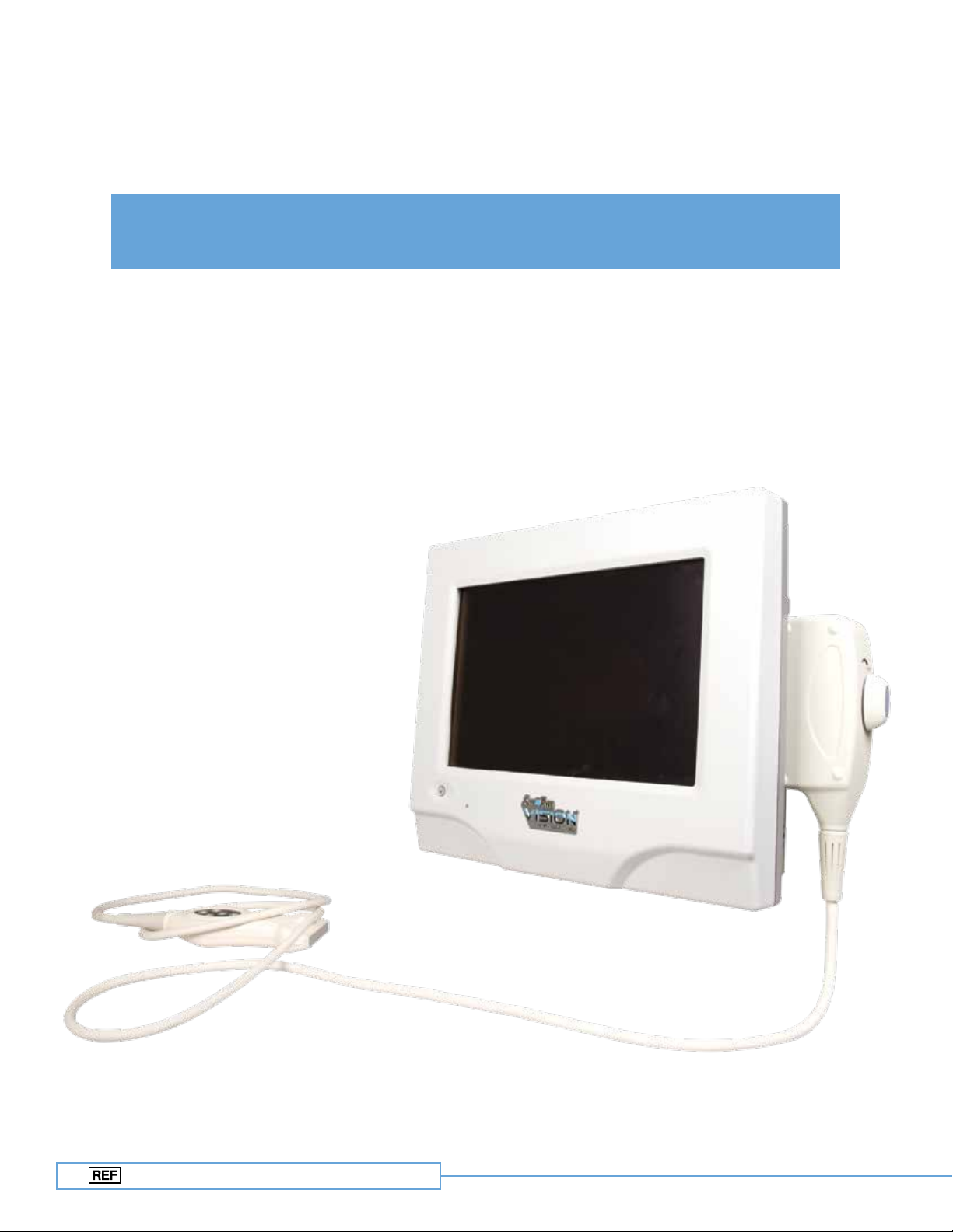
Site~Rite Vision* Ultrasound System
Technical Manual
9770057
Page 2
2
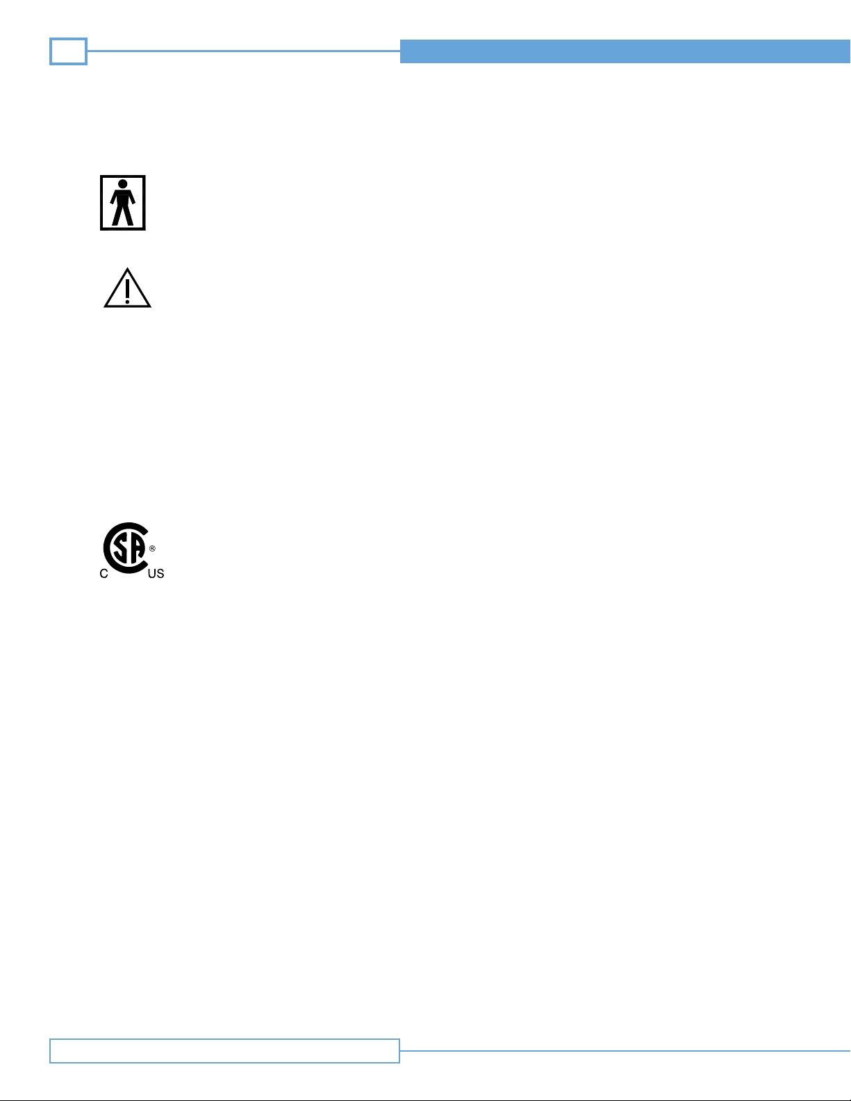
BF Type Equipment
Attention, see instructions for use
Site~Rite Vision* Ultrasound System
IPX1
Rx Only
Drip Proof Equipment
Federal (U.S.A.) law restricts this device
to sale by or on the order of a physician.
Medical Electrical Equipment
Classified by CSA with respect to Electric Shock,
Fire, and Mechanical Hazards only in accordance
with UL60601-1 and CAN/CSA C22.2 No. 601.1
Symbol Reference
Page 3

Technical Manual
Table of Contents
Section
Statement and Purpose1
System Overview2
2.1
2.1.1
2.1.2
2.1.3
2.2
2.2.1
2.2.2
2.3
3.1
3.2
3.3
3.3.1
3.3.2
3.4
Controls and Connections
Front Panel
Back Panel
Probe Attachment
Hardware
Component Overview
Power System
Software
Roll Stand Adjustments3
Keyboard Adjustment
Handle Adjustment
Display Adjustment
Display Rotation
Display Tilt
Locking the Casters
3
4.1
4.1.1
4.1.2
4.1.3
4.2
4.3
Technical Specications 4
General Specifications
Operating and Storage Conditions
A/C Adapter Specifications
System Battery Specifications
EMC Tables
Leakage Current
Repair and Troubleshooting5
Table of Contents
Page 4
4
Site~Rite Vision* Ultrasound System
Statement of Purpose1
This Site~Rite Vision* Ultrasound System Technical Manual is intended to provide technical specifications for the Site~Rite Vision* Ultrasound
System. The system is not field serviceable. For service requests, please call Bard Access Systems’ Technical/Clinical Support at (800) 443-3385.
Warnings and Precautions
Refer to Site~Rite Vision* Ultrasound System Hardware & Operating Instructions for Use (IFU) for a list of warnings and precautions.
System Overview2
Controls and Connections2.1
The Site~Rite Vision* Ultrasound System has user accessible features on the front and back panels, and an ultrasound probe connection on
the side of the unit.
Front Panel 2.1.1
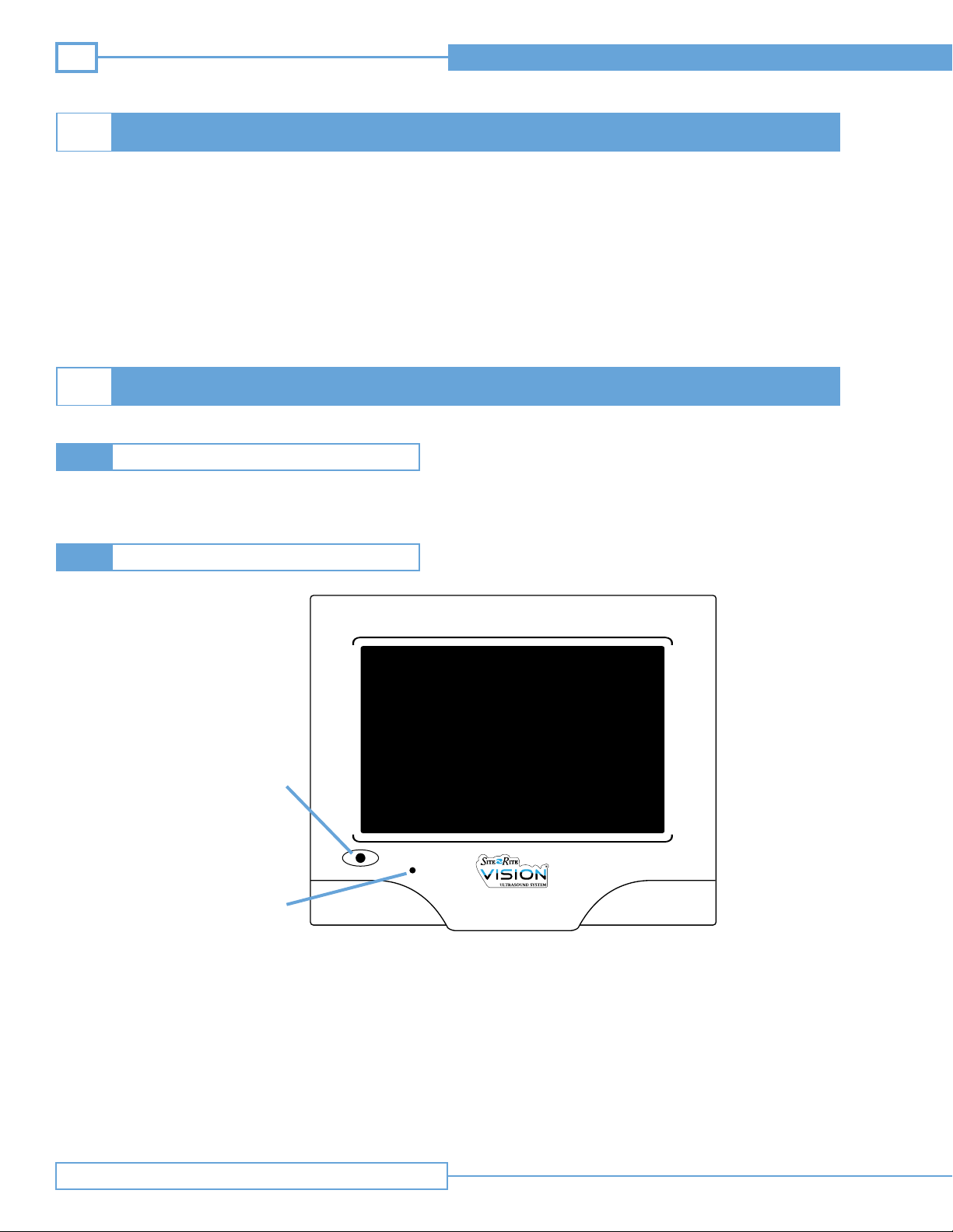
Power Button
Power LED
Figure 2.1.1 Front Panel
Press and hold the power button on the display for three seconds to turn the system on or off. The power LED indicates that the system is on.
Note: In standby mode the system remains powered and battery life will be depleted. Standby mode allows the system to power up into the
most recent state more quickly than returning from a full shutdown.
Note: Holding the power button down for 8 seconds can be used to power the system down via a “hard” shutdown. Repeatedly powering the
system down in this manner may damage the operating system and should only be used when other appropriate shutdown methods
are unavailable.
Statement of Purpose / System Overview
Page 5
Technical Manual
Back Panel2.1.2
5
Battery LEDVGA Port
Ethernet Port
USB Ports
The printer MUST be
connected to the
lowest USB port
VESA
Mount
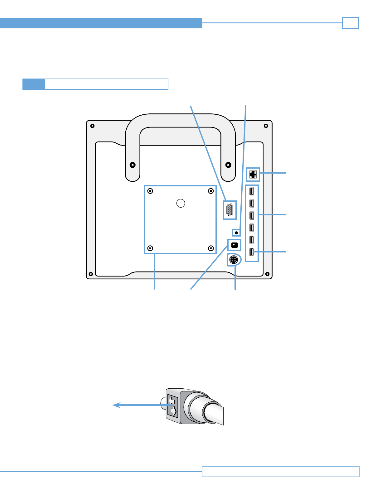
Figure 2.1.2 Back Panel
Insert cords for keyboard, printer, and A/C power adapter into designated ports on the ultrasound display as shown in Figure 2.1.2.
Note: The VGA and Ethernet connections are consistent with VGA and Ethernet standards.
Note: The printer power cable is identical on both ends. Both ends are compatible with both the printer and Site~Rite Vision* Ultrasound System.
Note: The AC adapter cable must be inserted with the flat side of the connector toward VESA mount and the rounded side toward the USB ports.
Printer
Power Port
A/C Adapter
Power Port
To ward VESA Mount
System Overview
Page 6
6
Table 2.1.2 Battery LED status
Site~Rite Vision* Ultrasound System
Powered A/C
Adapter
Detached
Detached
Attached
Attached
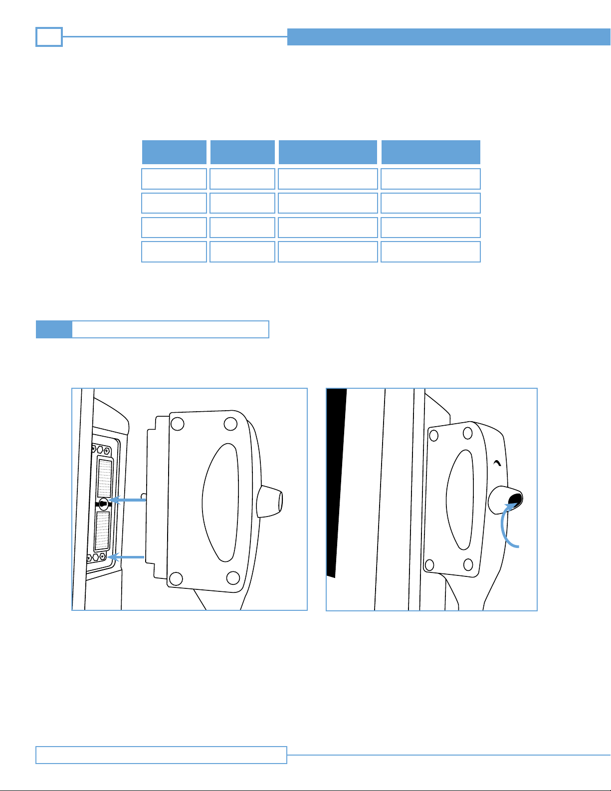
Probe Attachment2.1.3
To connect the probe to the display:
System Power
OFF
ON
OFF
ON
Battery
Not in use
In use
Charging
Charging
Battery LED Status
OFF
ON
BLINK
ON
Step 1. Insert Probe Connector Step 2. Twist to Lock
System Overview
Lock
Page 7
Technical Manual
Hardware2.2
Component Overview2.2.1
Sherlock* II /
Sherlock 3CG*
Sensor
Keyboard
USB Memory
Device
Printer
Data
Power
VISION UNIT
USB Module
Data /
Power
Power
Display and
Computing Platform
Data /
Power
Power Control
Module
Power
Data
Power Data
Data /
Power
Beamformer
Module
Battery
7
Ultrasound
Probe
Cooling Fan
Figure 2.2.1 Component Overview
A/C Adapter
Power Supply
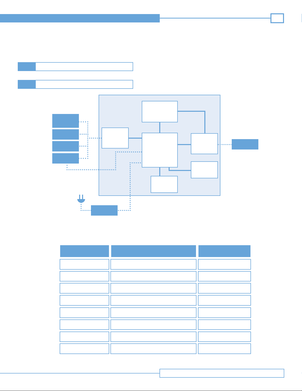
The Site~Rite Vision* Ultrasound System is composed of several major components as depicted in Figure 2.2.1. See Table 2.2.1 for a functional
description of each component.
Table 2.2.1 Major Components of the Site~Rite Vision* Ultrasound System
Plastic Housing/ Handle
(Cycoloy Resin)
Sheet Metal Housing
Power Control Module
Beamformer Module
USB Module
Lithium Ion Battery
Functional DescriptionComponent
Contain parts, mechanical
support, aesthetics
EMC protection,
Component mounting
Power management and distribution,
battery charging and communication, cooling
Signal Processing and
Ultrasound Probe connection
6 USB ports each with 5V
and 0.5 amps available
Power storage,
charge status
Within sheet metal housing
Within sheet metal housing
Within sheet metal housing
Within sheet metal housing
Location
Exterior
Within plastic housing
Fan
Display and
Computing Platform
Cooling
Processing, display data, provide user
interface, application management
Within sheet metal housing
Within plastic housing
System Overview
Page 8
8
Site~Rite Vision* Ultrasound System
Power System2.2.2
Ethernet
Connection (cable)
VGA
Connection (cable)
AC Adapter
(24V, 6.25A Output)
AC Power
Computing
Platform
Lithium Ion
Battery
Printer
Fan
Beamformer
20V, 3.25 A
Power Supply
Smart Battery
Charge Controller
9.3V 4.0A
Fused Power Supply
12V Power Supply
3.3V Power Supply
Power Control Module
3.3V Power
Supply
(Microcontroller)
Microcontroller
USB Ports
System Overview
USB Hub
5V Power Supply
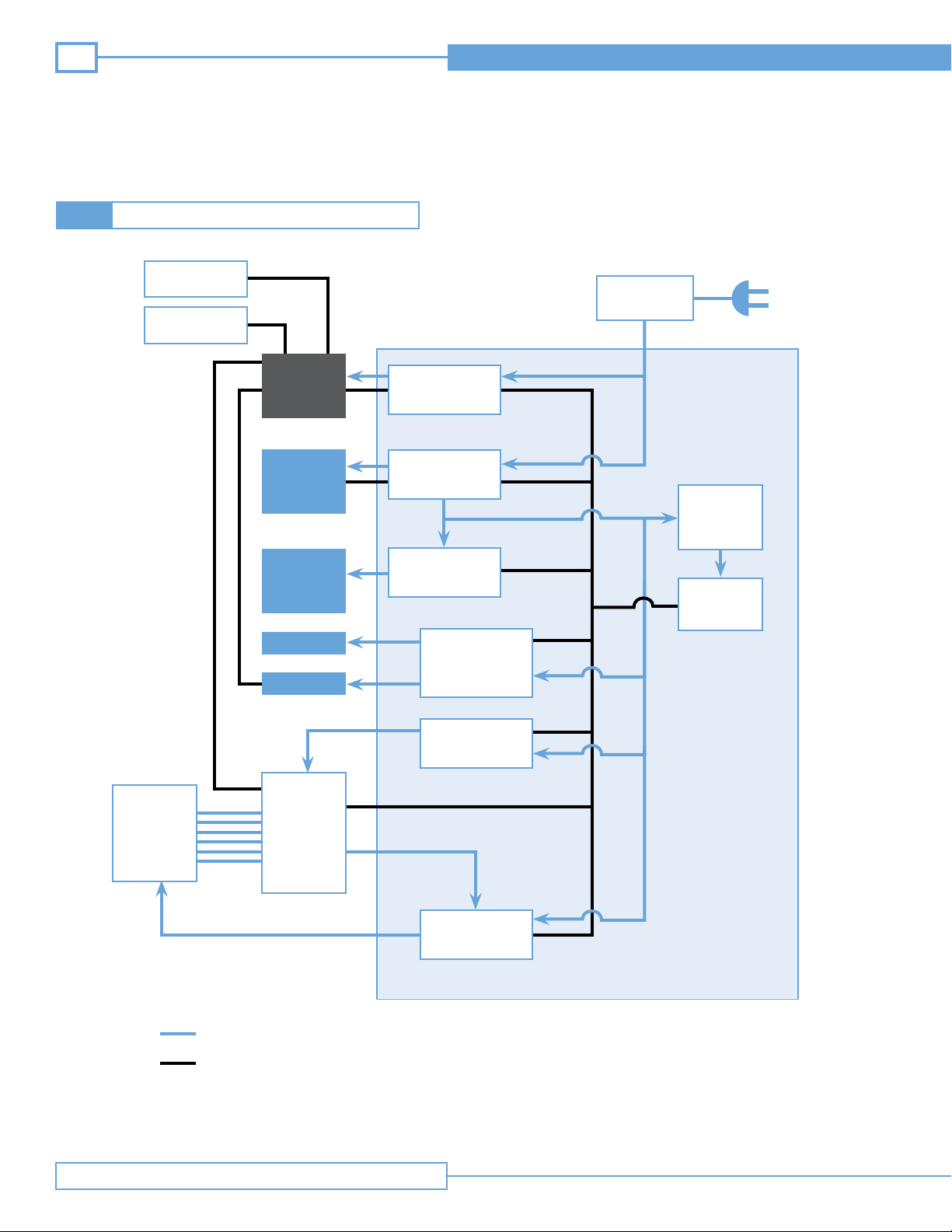
Power Connections are shown in blue
Data/Control Connections are shown in black
Figure 2.2.2 Power System
Page 9

Technical Manual
Table 2.2.2 Functional Description of Power System
A/C adapter 24 VDC Functional Description
9
A/C Adapter 24 VDC
Microcontroller
Smart Battery
Charge Controller
20V Power Supply
3.3V Supply
9.3V Supply
12V Supply
5V Supply
Provides power to the Site~Rite Vision* Ultrasound System and turns the
microcontroller on.
Turns power supply subsystems on and off depending on system inputs and
changes of state.
Controls charge and discharge of the battery and communicates with the battery
and microcontroller. The battery charges when wall A/C is connected.
Power for the computing and display platform for function and internal
battery charging.
Power for the microcontroller
Power for the printer
Power for the fan and the ultrasound module
Power for each USB port. Power provided only when the system is on.
USB Hub
Data control for USB ports. This is functional only when the system is on.
System Overview
Page 10
10
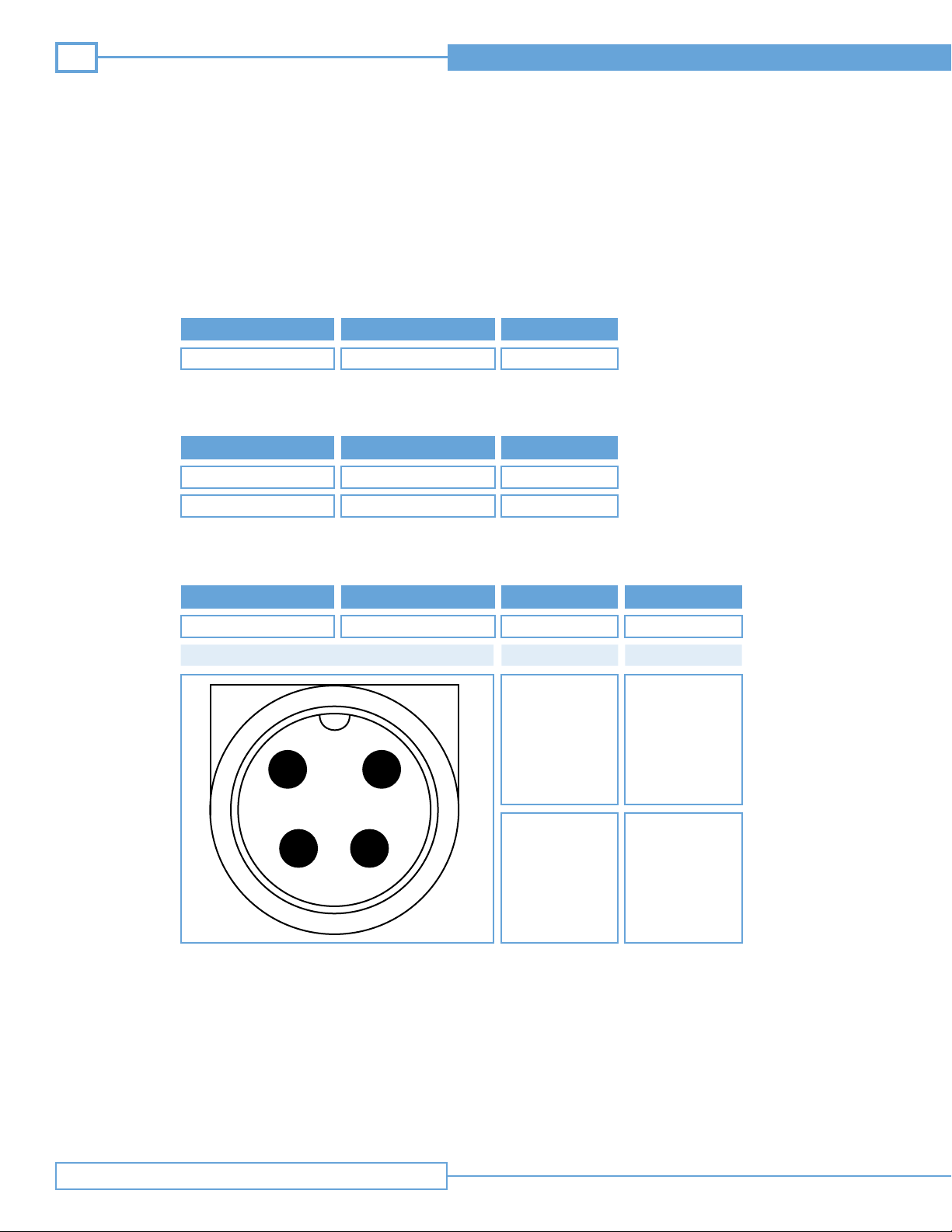
Voltage Inputs:
Connection
Power Specifications
Input Voltage (V
DC
Input Current (A)
)
Site~Rite Vision* Ultrasound System
Main Power
Voltage Outputs:
Connection
USB
Printer Power
A/C Adapter Power Supply Specifications:
)
Voltage Input (V
100 - 240
AC
Input Frequency (V
Diagram
2
24 ± 5%
Input Voltage (V
5 ± 5%
9.3 ± 5%
47 - 63
1
DC
6.25
)
Input Current (A)
.5 per port
4 (fuse limited)
)
Input Current (A) Output (W)
AC
1.63 – 0.7 150
Pin
1, 3
Function
Return
Fusing:
The Site~Rite Vision* Ultrasound System has several fuses which are not serviceable. These include fusing
for the A/C adapter, the 24V input to the power control module, the 20V supply to the computing and display
platform and the 9.3 volt supply to the printer. For power system failure contact Bard Access Systems’
technical/clinical support at (800) 443-3385.
System Overview
4
3
2, 4
Power
Page 11
Technical Manual
Software:2.3
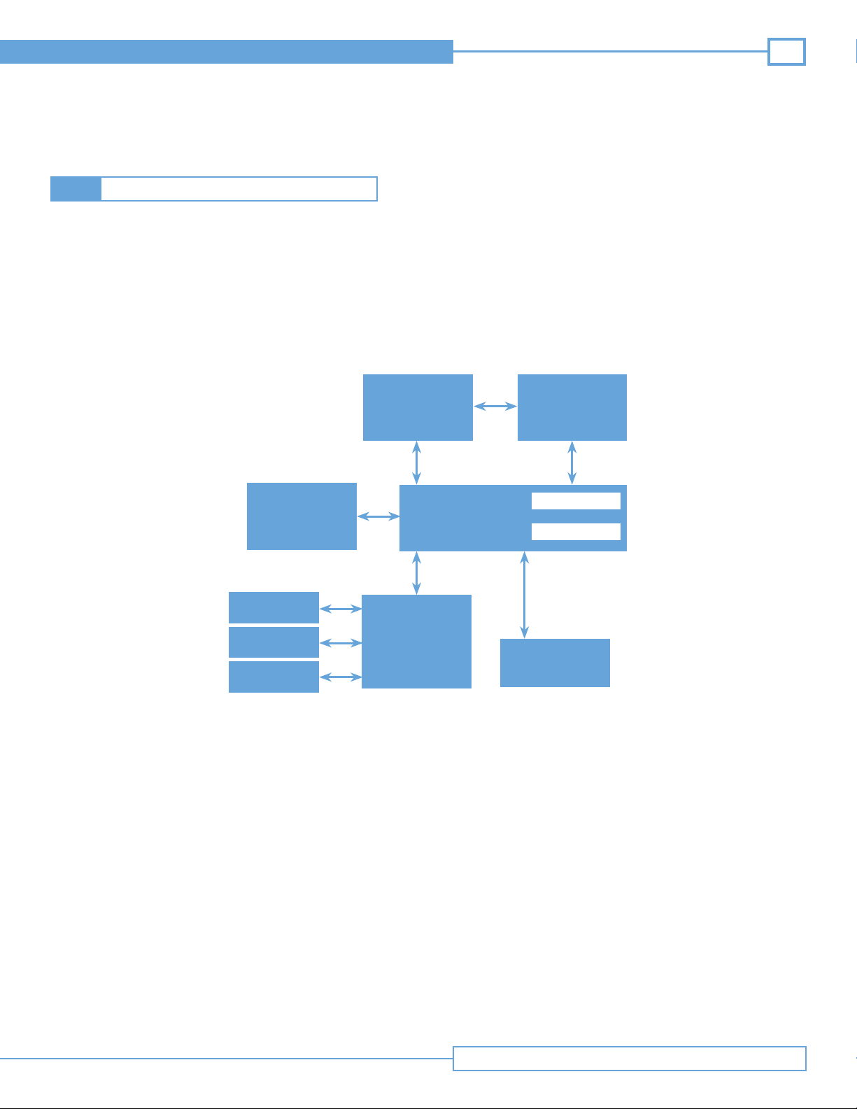
Site~Rite Vision* Ultrasound System runs on a Microsoft Windows* based operating system. Figure 2.3 depicts the software application interactions of the Site~Rite Vision* Ultrasound System. The application toolbar located in the bottom left corner of the
screen acts as the central control point of the Site~Rite Vision* Ultrasound System. It launches and closes applications and offers
configuration options. The operating instructions for each application are described in their respective instructions for use.
Sherlock* II/
Site~Rite Vision*
Software
Sherlock 3CG*
Software
11
Battery Monitor
DICOM Software
Calibration Tool
Skin Selection Tool
Date and Time
Properties
Application Toolbar
AC Power Icon
Configuration
Application
Power Control
Application
Figure 2.3 Site~Rite Vision* Ultrasound System Application Interactions
System Overview
Page 12
12
Site~Rite Vision* Ultrasound System
Roll Stand Adjustments3
Keyboard Adjustment3.1
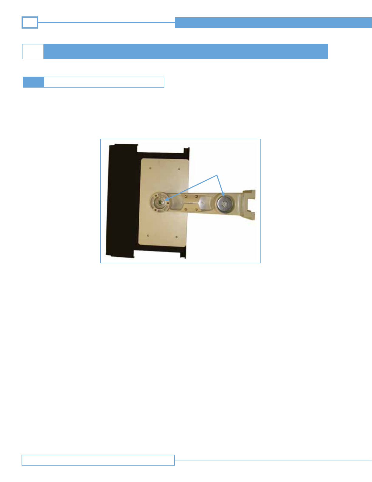
Rotation of the keyboard arm can be adjusted by tightening or loosening two fasteners on the bottom side of the keyboard arm with
a ½ inch socket wrench. After the arm has been positioned, the fasteners can be tightened to lock the arm in position.
Note: Tightening the keyboard arm fasteners too much will prevent the user from adjusting the arm during use. Loosening the
keyboard arm fasteners too much may cause the arm to disassemble.
Keyboard Adjustment
Fasteners
Figure 3.1 Keyboard Adjustment
Roll Stand Adjustments
Page 13
Technical Manual
Handle Adjustment3.2
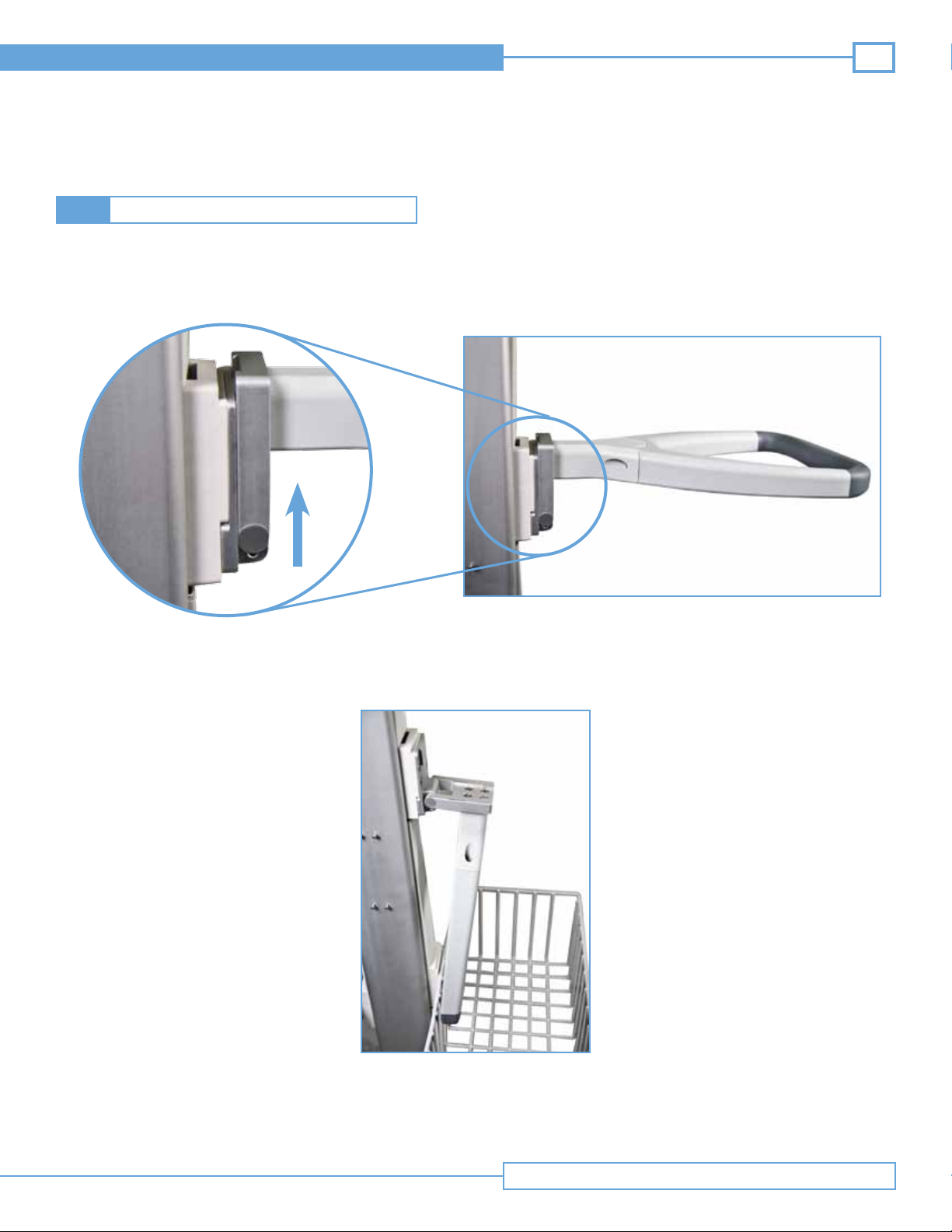
The roll stand handle is designed to fold down for storage and fold up for transport.
The hinge will function after the handle has been lifted up.
To fold handle down:
13
Step 1: Lift up the handle
Step 2: Fold handle down
The handle can be put in the transport position by reversing the steps.
Roll Stand Adjustments
Page 14
14
Site~Rite Vision* Ultrasound System
Display Adjustment3.3
Display Rotation3.3.1
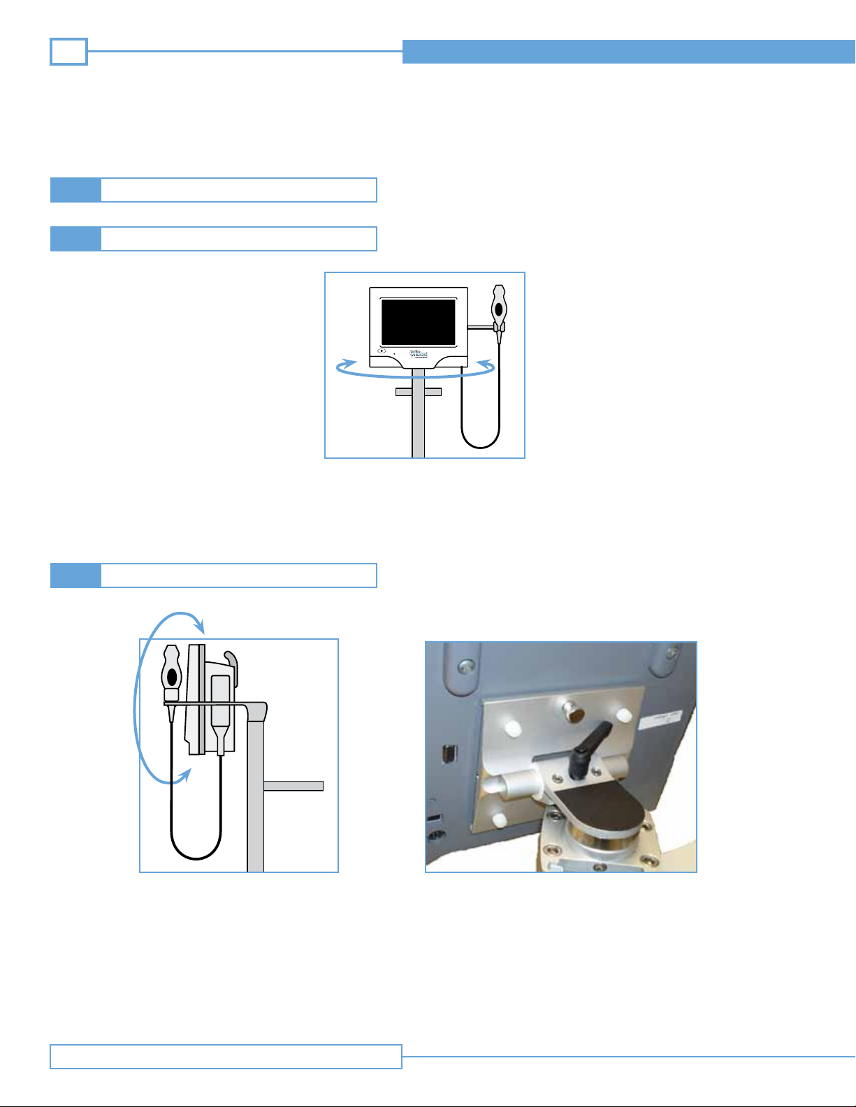
The roll stand is designed to allow the user to rotate the display 160° in the horizontal plane, 80° to the right and 80° to the left.
To adjust the position of the display in the horizontal plane, turn the display to the desired position.
Note: Extending the rotation of the display more than 80° in either direction could result in the system tipping, causing injury and/or
damage to the system.
Display Tilt3.3.2
Figure 3.3 Display Tilt Clamp
The display can be tilted by rotating the display on its vertical pivot. If the tilt is too tight or too loose, this can be adjusted.
Adjusting tilt movement:
• Loosen the display tilt by rotating the clamp lever counter-clockwise.
• Tighten the display tilt by rotating the clamp lever clockwise.
• Reposition the display tilt clamp lever by lifting up and rotating.
Roll Stand Adjustments
Page 15
Technical Manual
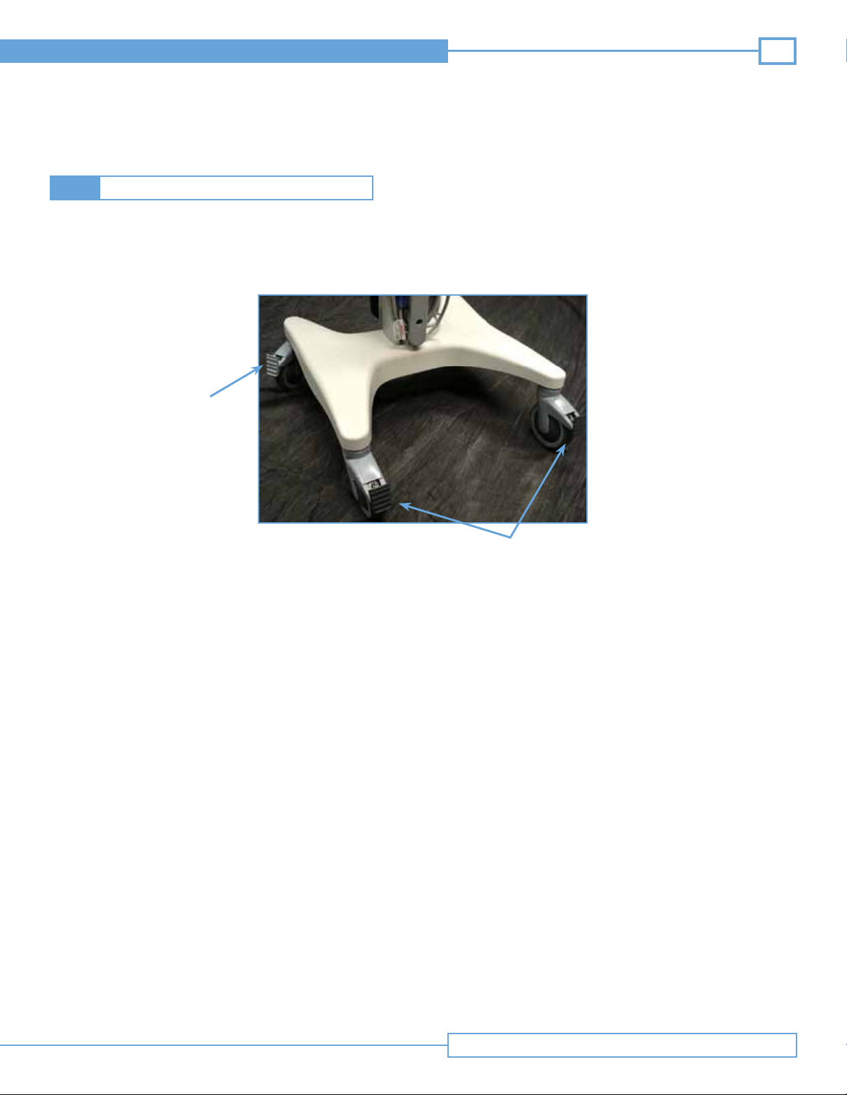
Locking the Casters3.4
There are three caster locks on the roll stand. Two are dark gray in color; one is light gray in color. The dark gray caster locks fix the
position of the casters, but still allow the casters to roll. The light gray caster lock is a brake and fixes the position of the caster and
prevents the castor and stand from rolling.
Brake
15
Figure 3.4 Caster Locks
Fixed Position
Roll Stand Adjustments
Page 16

16
Site~Rite Vision* Ultrasound System
Technical Specifications 4
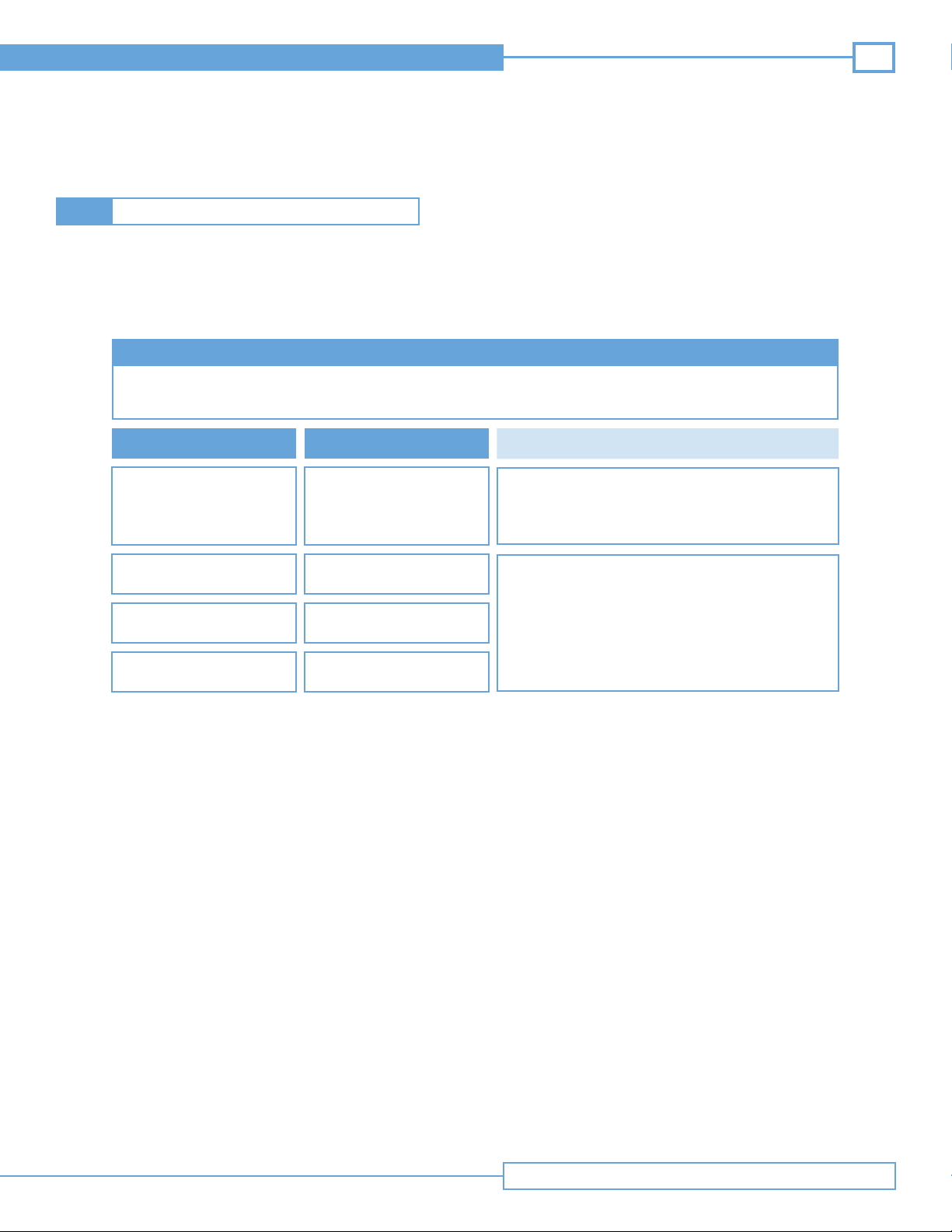
4.1
4.1.1
General Specications
Operating and Storage Conditions
Operating Temperature:
Storage Temperature:
Operating Humidity:
Storage Humidity:
Dimensions:
Weight:
Power Sources:
Power Consumption:
Monitor Size:
IEC 60601-1:
59ºF to 104ºF (10ºC to 40ºC)
0ºF to 104ºF (-18ºC to 40ºC)
5% to 85% Relative Humidity (non-condensing)
5% to 95% Relative Humidity (non-condensing)
14”W x 12”H x 5”D
14 lbs
Internal battery, AC adapter
60-180W
1280 x 800 Widescreen format
Class II, Continuous Operation, Internally Powered Equipment, Not Category
AP or APG Equipment, Not protected against ingress of water.
4.1.2
4.1.3
A/C Adapter Specications
Manufacturer:
Model Number:
Input Voltage:
Input Current (Max):
Output Voltage:
Output Current (Max):
XP Power
AMM150PS24
100-240 VAC, 50/60 Hz
1.6 A at 115 VAC, 0.8 A at 230 VAC
24 VDC
6.25 Amps
System Battery Specications
Battery Chemistry:
System Run Time
on Full Charge:
Charge Time (Full):
Lithium Ion
3.0 Hours
8.0 Hours
Technical Specifications
Page 17
Technical Manual
17
4.2
EMC Tables
Warning: The use of accessories other than those specified in Section 2.3 of the Site~Rite Vision* Ultrasound System Hardware
and Operating System instructions for use may result in increased emissions or decreased immunity of the Site~Rite
Vision* Ultrasound System.
Site~Rite Vision* Ultrasound System EMC Tables
GUIDANCE AND MANUFACTURER’S DECLARATION - EMISSIONS
The Site~Rite Vision* Ultrasound System is intended for use in the electromagnetic environment specified below.
The customer or user of the Site~Rite Vision* Ultrasound System should ensure that it is used in such an environment.
Emissions Test Compliance
RF Emissions CISPR 11
RF Emissions CISPR 11
Harmonics IEC 61000-3-2
Group 1
Class A
Class A
Electromagnetic Environment – Guidance
The Site~Rite Vision* Ultrasound System uses RF
energy only for its internal function. Therefore, its RF
emissions are very low and are not likely to cause any
interference in nearby electronic equipment.
The Site~Rite Vision* Ultrasound System is suitable
for use in all establishments, other than domestic,
and those directly connected to the public low-voltage
power supply network that supplies buildings used for
domestic purposes.
Flicker IEC 61000-3-3
Note: While the Site~Rite Vision* Ultrasound System is not classified to be used in a domestic environment, there may be a need
for the health care professional to use the system for a limited duration.
Warning: This system, with its applicable accessories, is intended for use by healthcare professionals only. If used in a domestic
environment, this system may cause radio interference or may disrupt the operation of nearby equipment. It may be
necessary to take mitigation measures such as re-orienting or relocating the Site~Rite Vision* Ultrasound System or
shielding the location.
Complies
Technical Specifications
Page 18

18
Site~Rite Vision* Ultrasound System
Guidance and Manufacturer’s Declaration – Immunity
The Site~Rite Vision* Ultrasound System is intended for use in the electromagnetic environment specified below.
The customer or user of the Site~Rite Vision* Ultrasound System should ensure that it is used in such an environment.
Immunity Test
ESD
EN/IEC 61000-4-2
EFT
EN/IEC 61000-4-4
Surge
EN/IEC 61000-4-5
Voltage
Dips/Dropout
EN/IEC 61000-4-11
±6kV Contact
±8kV Air
±2kV Mains
±1kV Input/Output Lines
±1kV Differential
±2kV Common
>95% Dip for 0.5 Cycle
60% Dip for 5 Cycles
30% Dip for 25 Cycles
>95% Dip for 5 Seconds
Compliance LevelEN/IEC 60601 Test Level
±6kV Contact
±8kV Air
±2kV Mains
±1kV Input/Output Lines
±1kV Differential
±2kV Common
>95% Dip for 0.5 Cycle
60% Dip for 5 Cycles
30% Dip for 25 Cycles
>95% Dip for 5 Seconds
Electromagnetic Environment
Guidance
Floors should be wood, concrete or
ceramic tile. If floors are synthetic,
the relative humidity should be at
least 30%.
Mains power quality should be that
of a typical commercial or hospital
environment.
Mains power quality should be that
of a typical commercial or hospital
environment.
Mains power quality should be
that of a typical commercial or
hospital environment. If the user
of the Site~Rite Vision* Ultrasound
System requires continued
operation during power mains
interruptions, it is recommended
that the Site~Rite Vision* Ultrasound
System be powered from an uninterruptible power supply or battery.
Power Frequency
50/60 Hz
Magnetic Field
EN/IEC 61000-4-8
Technical Specifications
3 A/m
3 A/m
Power frequency magnetic fields
should be that of a typical commercial or hospital environment.
Page 19
Technical Manual
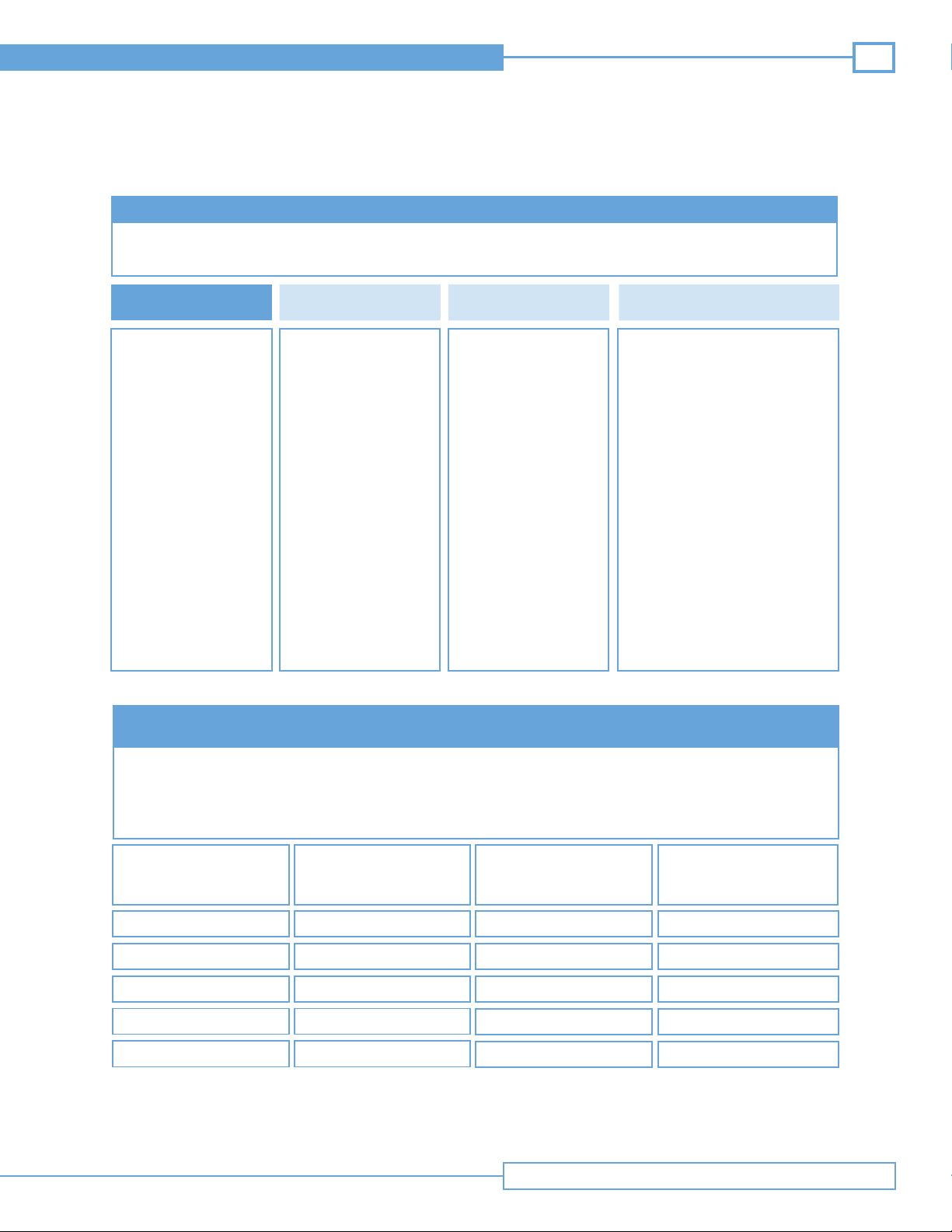
Guidance and Manufacturer’s Declaration – Emissions
The Site~Rite Vision* Ultrasound System is intended for use in the electromagnetic environment specified below. The
customer or user of the Site~Rite Vision* Ultrasound System should ensure that it is used in such an environment.
19
Immunity Test
Conducted RF
EN/IEC 61000-4-6
Radiated RF
EN/IEC 61000-4-3
Recommended Separation Distances between portable and mobile RF Communications
Compliance LevelEN/IEC 60601 Test Level
3 Vrms
150 kHz to 80 MHz
3 V/m
80 MHz to 2.5 GHz
equipment and the Site~Rite Vision* Ultrasound System
3 Vrms
3 V/m
Electromagnetic Environment
Guidance
Portable and mobile communications
equipment should be separated from
the Site~Rite Vision* Ultrasound
System by no less than the distances
calculated/listed below:
D = 1.2 (√ P)
D = 1.2 ( √ P) 80 to 800 MHz
D = 2.3 ( √ P) 800 MHz to 2.5 GHz
where P is the max power in watts
and D is the recommended separation distance in meters.
Field strengths from fixed transmitters, as determined by an electromagnetic site survey, should be less
than the compliance levels.
Interference may occur in the
vicinity of equipment containing a
transmitter.
The Site~Rite Vision* Ultrasound System is intended for use in the electromagnetic environment in which radiated
disturbances are controlled. The customer or user of the Site~Rite Vision* Ultrasound System can help prevent electromagnetic interference by maintaining a minimum distance between portable and mobile RF Communications Equipment
and the Site~Rite Vision* Ultrasound System as recommended below, according to the maximum output power of the
communications equipment.
Max Output Power
(Watts)
0.01
0.1
1
10
100
Separation (m)
150 kHz to 80 MHz
D = 1.2( √ P)
.1166
.3689
1.1666
3.6893
11.6666
Separation (m)
80 to 800 MHz
D = 1.2 ( √ P)
.1166
.3689
1.1666
3.6893
11.6666
Separation (m)
800 MHz to 2.5 GHz
D =2.3( √ P)
.2333
.7378
2.3333
7.3786
23.3333
Technical Specifications
Page 20
20
Site~Rite Vision* Ultrasound System
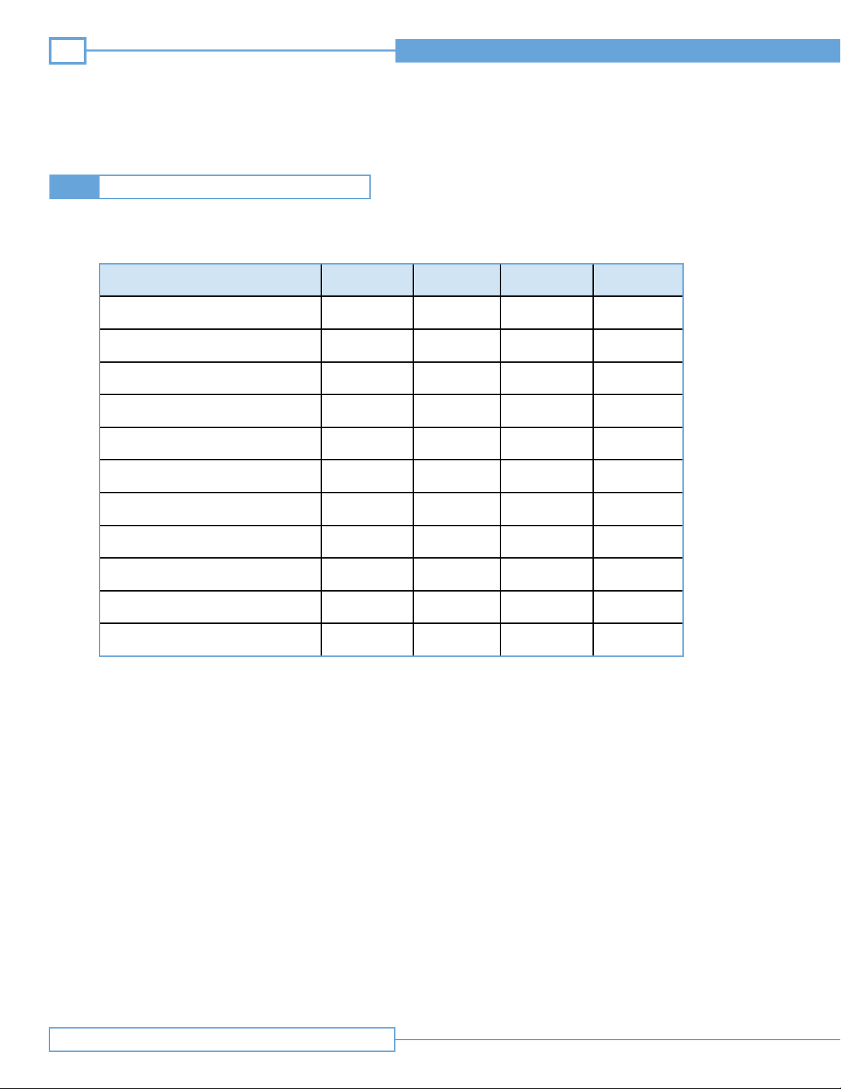
Leakage Current4.3
Leakage current does not exceed allowable limits according to IEC60601-1:1988, Medical Electrical Equipment, Part 1: General
Requirements for Safety, including Amendment 1 and Amendment 2. Measured leakage currents are provided in the table below.
Type of leakage current and test condition
(including single faults)
EN (N.C.) 264Vrms 63Hz
EN (S.F.C.) 264Vrms 63Hz
P (N.C.) 264Vrms 63Hz
P (S.F.C.) 264Vrms 63Hz
PM 264Vrms 63Hz
PA (N.C.) 264Vrms 63Hz
PA (S.F.C.) 264Vrms 63Hz
EN (Internally powered) 24Vdc N/A
P (Internally powered) 24Vdc N/A
PM (Internally powered) 24Vdc N/A
PA (Internally powered) 24Vdc N/A
Supply Voltage
Supply
Frequency
Measured Max Remarks
18μA (B)
25μA (A)
29μA (B)
40μA (A)
5μA (B)
7μA (A)
7μA (B)
124μA (A)
9μA (B)
24μA (A)
6μA (B)
5μA (A)
7μA (B)
5μA (A)
4μA (B)
4μA (A)
3μA (B)
3μA (A)
22μA (B)
18μA (A)
3μA (B)
3μA (A)
Ultrasound
probe
Ultrasound
probe
Ultrasound
probe
Ultrasound
probe
Ultrasound
probe
Technical Specifications
Page 21
Technical Manual
Repair and Troubleshooting5
The Site~Rite Vision* Ultrasound System does not require calibration or preventative maintenance and is not field serviceable.
There are several simple troubleshooting steps that can be performed before the system should be returned for service.
Call Bard Access Systems’ technical/clinical support at (800) 443-3385 for any other problems that arise.
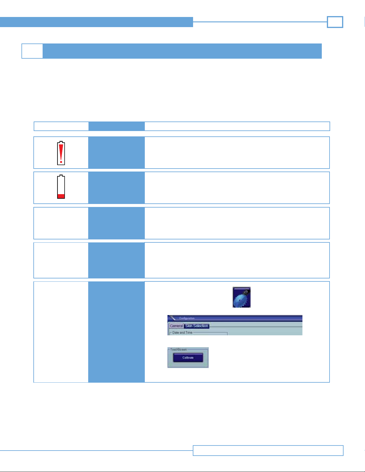
Table 5.1 System Troubleshooting
21
Power Problem
A/C adapter indicator
does not change states
SymptomSympton
Battery Error
Low Battery
System will not turn
on or powers on but
immediately turns off
Connection error
Solution
Contact the Bard Access Systems’ technical/clinical support at (800) 443-3385.
Connect system to an A/C outlet for operation and battery recharge.
• Press and hold the power button for at least 3 seconds to power on.
• Connect system to an A/C outlet for operation and battery recharge
Note: If error persists, contact the Bard Access Systems’ technical/clinical
support at (800) 443-3385
1. Shutdown the system
2. Unplug the A/C adapter and plug back in
3. Turn the system on
Note: If error persists, contact the Bard Access Systems’ technical/clinical
support at (800) 443-3385.
1. Press the configuration button
Touch screen
misalignment
2. Open the General tab
Touch screen
needs calibration
3. Press the Touch Screen calibrate button
4. Follow the onscreen prompts to complete calibration.
Continued on next page
Repair and Tr oubleshooting
Page 22
22
Continued from previous page
Printer problems
Printer error
Site~Rite Vision* Ultrasound System
1. Check to ensure printer is on.
2. Check to ensure printer has paper.
3. Check printer power and USB connections. Ensure that the printer is
connected to the lowest USB port.
4. Note: If error persists, contact the Bard Access Systems’ technical/clinical
support at (800) 443-3385.
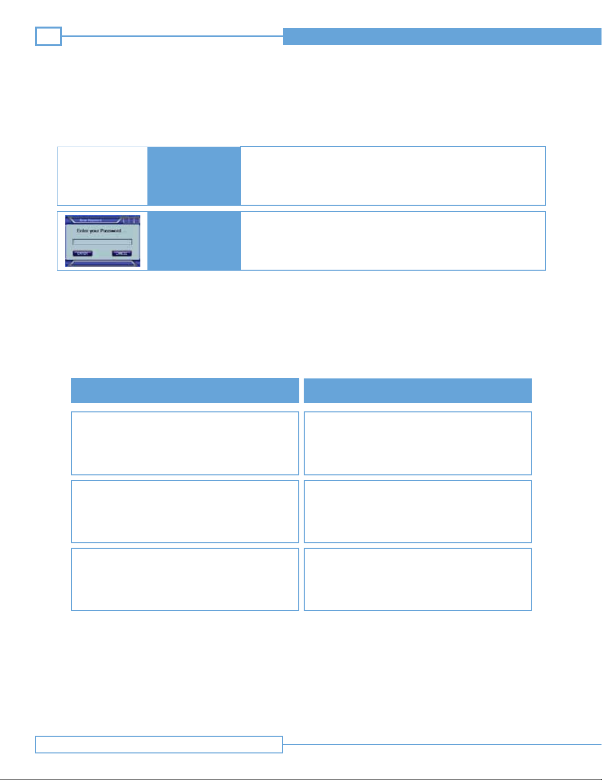
Forgot System
Password
Note: Check that all cables are in good repair with no fraying or exposed copper. Ensure that connectors are in good repair with
pins and housings straight and free of damage.
Error
Files fail to transfer.
Message “Error Trasferring File” or “Status:
Contact Bard Access Systems technical/clinical support at (800) 443-3385.
Table 5.2 DICOM Troubleshooting
Solutions
1. Check Ethernet cable connection.
2. DICOM not configured properly. Call your PACS
administrator. Configure the DICOM Application.
3. Contact Bard Access Systems’ technical/clinical
support at (800) 443-3385.
1. Ensure that all fields for Name, ID, etc. are complete.
Processing Failure”
Message “Attempt to connect timed out without
establishing a connection”
Repair and Tr oubleshooting
1. Check that the system is connected to a working
network connection
2. Check that the IP address/port in the DICOM application matches the server’s IP address/port.
3. Check that the server is running.
Page 23
Technical Manual
23
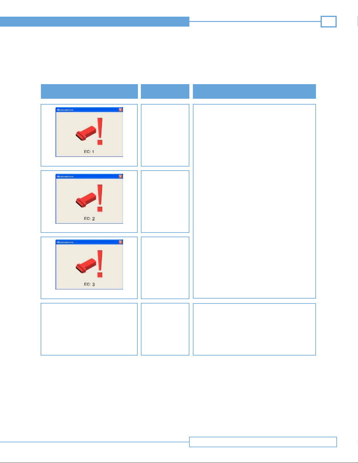
Table 5.3 Site~Rite Vision* Ultrasound System Troubleshooting
Error Code Symptom
EC1: Beamformer Problem
EC 2: Voltage Levels Out of Range
No ultrasound
image
No ultrasound
image
Solutions
1. Battery is low. Plug the display into A/C Power.
2. Check A/C adapter.
3. Reboot System.
Contact Bard Access Systems’ technical/clinical
support at (800) 443-3385.
EC 3: System Initialization Error
No ultrasound
image
Poor Image QualityUltrasound Image
• Follow the recommended image optimization
in Table 5.4 and 5.5. See the Site~Rite Vision*
Ultrasound System Instructions for Use for
additional information.
• If the image issue cannot be resolved, contact
Bard Access Systems’ technical/clinical support
at (800) 443-3385.
Repair and Tr oubleshooting
Page 24
24
Site~Rite Vision* Ultrasound System
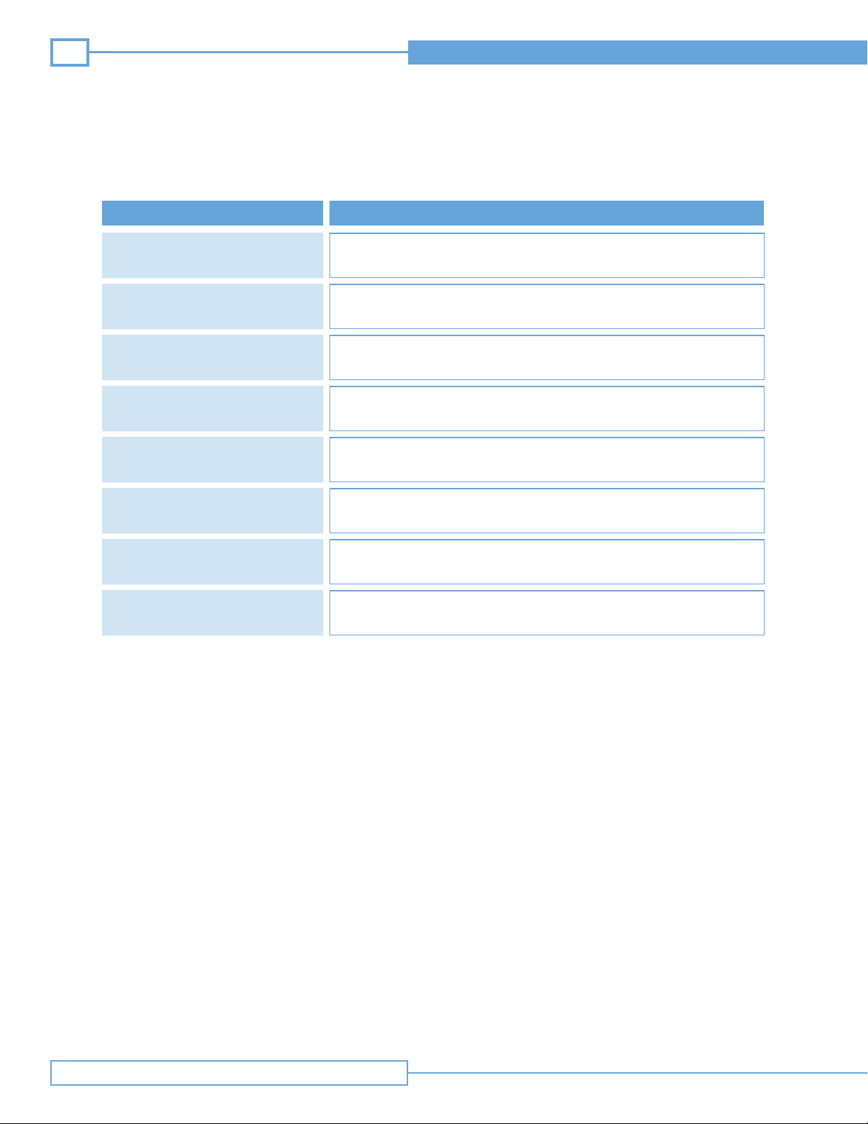
Table 5.4 Recommended Image Optimization Sequence
STEP
Select the appropriate procedural
setting from the procedural toolbar.
Select the depth required to
see the target structure.
Adjust focus to align with
the target structure.
Adjust frequency according
to the target depth.
Adjust Gain and/or TGC
to user preference.
Adjust Contrast to user preference
and procedural need.
Adjust power.
Save as user preset.
Start from a known optimized image.
Visualize target depth/structure to start optimizing image.
The focal point on the image has the best image resolution.
Higher frequency has the best resolution and should be used for shallow imaging.
Lower frequency has the best penetration and should be used for deep imaging.
Gain adjusts overall image brightness.
TGC adjusts brightness in sections of the image.
High contrast is black and white.
Low contrast is many shades of gray.
Higher power makes the image brighter.
Once the image is adjusted, the clinician may want to save these custom
settings for future use.
Note: All steps may not be required to optimize the image.
Note: Depth, Focus, Frequency, and Power affect the acoustic output and the MI (Mechanical Index) and TI (Thermal Index) values.
The MI and TI values should be monitored as these parameters are adjusted so that the lowest values of MI and TI are used that
achieve the desired image. See the Site~Rite Vision* Ultrasound System instructions for use for further information regarding MI, TI
and prudent use.
Repair and Tr oubleshooting
Page 25
Technical Manual
STEP
25
Table 5.5 Recommended Doppler (CFM mode) Optimization Sequence
Select or adjust to an optimized
image for the targeted structure
Place the Doppler window over
the structure of interest
Adjust Doppler window size
Angle the probe relative to
the structure of interest
Adjust Flow Range
Adjust Gain
Adjust power
Save as user preset
Start from a known optimized image. See Table 5.4.
Flow information will only appear in the Doppler window.
Flow information will only appear in the Doppler window.
Angle of the probe relative to the structure has a significant affect on the Doppler data.
Consistent Doppler data is obtained if the probe is not perpendicular to the flow.
Start at a low flow range and adjust upward until flow information is consistent and
visible in the target structure. Black indicates flow information is outside the flow range.
Increasing gain will enhance the Doppler data, but may add noise
(red/blue speckles) in non targeted areas.
Increasing power will enhance the Doppler data, but may add noise
(red/blue speckles) in non targeted areas
Once the image is adjusted, the clinician may want to save these custom
settings for future use.
Note: Blue denotes flow away from the probe. Red denotes flow towards the probe.
Note: All steps may not be required to optimize the image.
Note: Doppler power, Doppler Window Depth and Doppler Window Size affect the acoustic output and the MI (Mechanical Index)
and TI (Thermal Index) values. The MI and TI values should be monitored as these parameters are adjusted so that the
lowest values of MI and TI are used that achieve the desired image. See the Site~Rite Vision* Ultrasound System
instructions for use for further information regarding MI, TI and prudent use.
Repair and Tr oubleshooting
Page 26

26
An issued or revision date for this document is included for the user's information. In the event two years have elapsed between this
date and product use, the user should contact Bard Access Systems, Inc. to see if additional product information is available.
Revision date: September 2010
Site~Rite Vision* Ultrasound System
Manufactured for:
Bard Access Systems, Inc.
605 North 5600 West
Salt Lake City, UT 84116 U.S.A.
1-(801)-522-5000
Customer Service: 1-(800)-545-0890
Technical/Clinical Support: 1-(800)-443-3385
Fax: 1-(801)-522-4948
www.bardaccess.com
* Bard, Sherlock, Sherlock 3CG and Site~Rite Vision are trademarks and/or registered trademarks of C. R. Bard, Inc.
All other trademarks are the property of their respective owners.
Site~Rite* Vision Ultrasound System
© 2010 C. R. Bard, Inc. All rights reserved.
0725009 1009R
Contact Information
 Loading...