

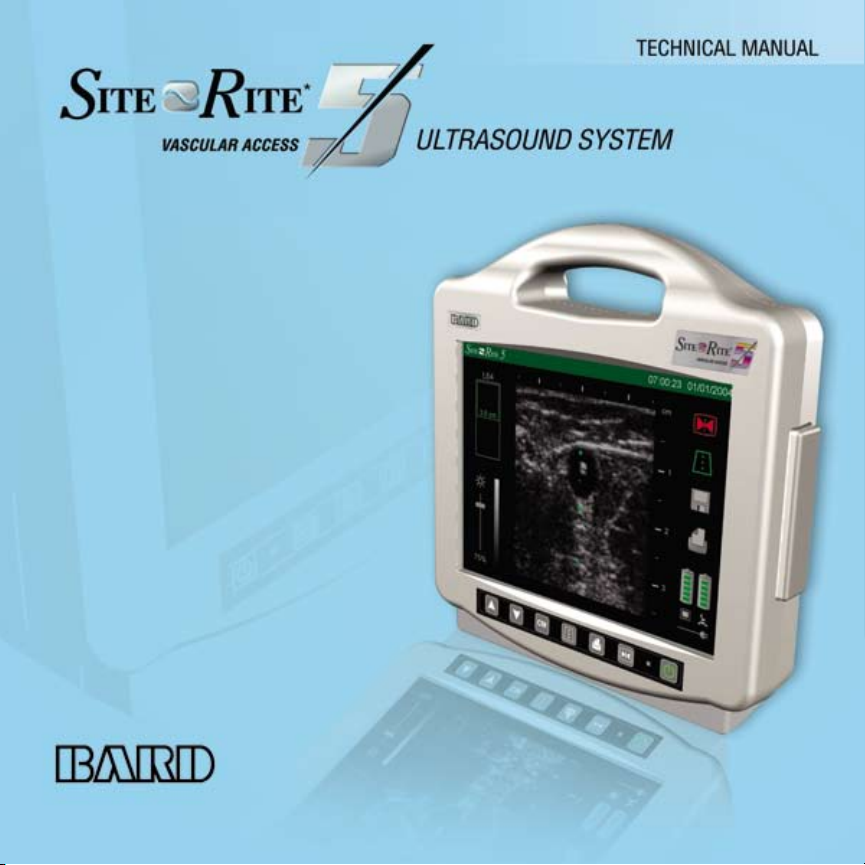
Page 1

Site~Rite* 5 Ultrasound System
Manufactured by:
Bard Access Systems, Inc.
Salt Lake City, UT 84116
U.S.A.
(801) 595-0700
Customer Service: (800) 545-0890
Technical/Clinical Support: (800) 443-3385
Fax: (801) 595-4948
www.bardaccess.com
An issued or revision date for these instructions is included for the users information. In the event two years have elapsed between this date and
product use, the user should contact Bard Access Systems, Inc. to see if additional product information is available.
Revision date: May, 2006.
* Bard and Site~Rite are trademarks and/or registered trademarks of C. R. Bard, Inc. or an affiliate.
Copyright © 2006 C. R. Bard, Inc. All Rights Reserved.
0712929 0605R
Page 2
Page 3

Page 4
Page 5
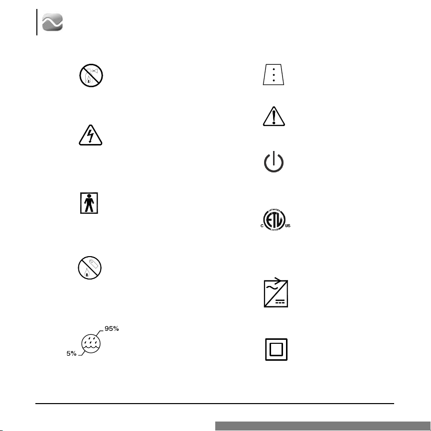
2
Site~Rite* 5 Ultrasound System
Do not operate in the presence
of flammable anesthetics
Dangerous Voltage
BF Type Equipment
Do Not Dispose of
Battery Pack In Fire
Humidity Parameters
Dot Markers Active
Warning: Refer to
Manual Before Use
Power/Stand-by
Medical Electrical Equipment
Classified by ETL with respect
to Electric Shock, Fire, and
Mechanical Hazards only in
accordance with UL60601-1
and CAN/CSA C22.2 No. 601.1
AC Adapter
Class II Equipment
Page 6
Technical Manual
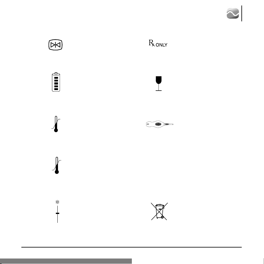
10
o
C
35
o
C
15
o
C
38
o
C
3
Freeze Image
Battery Pack
Storage Temperature
Parameters
Operating Temperature
Parameters
Gain
cm
Prescription Only
Fragile
Ultrasound Probe
Depth (In Centimeters)
Do not dispose with
ordinary municipal waste
Page 7

4
Site~Rite* 5 Ultrasound System
Page 8

Table of Contents
Section
1 Warranty
2 Warnings, Precautions and Notes
3 Site~Rite
3.1 Power Source
3.2 Scanner Assembly
3.3 Transducer Assembly
3.4 Front Panel Controls
3.5 Display Screen Information
4 Installing Site~Rite* 5 Software
5 Calibrating the Internal Battery
6 Troubleshooting & Error Screens
7 Site~Rite
7.1 Operating and Storage Conditions
7.2 Scanner Specifications
7.3 Probe Specifications
7.4 Power Supply Specifications
*
5 Ultrasound System Description
*
5 System Specifications
Technical Manual
5
8 Standards Information
9 Disposal Information
Page 9

6
Site~Rite* 5 Ultrasound System
1 Warranty
The manufacturer, Bard Access Systems, warrants this product against defects in material and workmanship for a period of one year from the date of original purchase, and agrees to repair, or at Bard
Access Systems' discretion, replace any defective unit free of charge. The warranty on the repaired or
replaced unit continues from the purchase date of the original unit. This warranty does not cover damages resulting from misuse, abuse, modification, or alteration of the Site~Rite* 5 System.
The following actions void the warranty of the Site~Rite* 5 System:
• Opening or servicing the scanner or the probe housing.
• Removal of system labels by anyone other than by Bard Access Systems
authorized service personnel.
• Opening or servicing the battery pack or the combination A/C adapter and battery
charger by anyone other than Bard Access Systems authorized service personnel.
• Connecting the Site~Rite* 5 scanner to any power source other than the Site~Rite* 5
combination A/C adapter and battery pack.
• Connecting the Site~Rite* 5 scanner to any A/C adapter other than the one
provided with the scanner.
• Connecting the Site~Rite* 5 System to any unauthorized accessory.
Page 10

Technical Manual
2 Warnings, Precautions and Notes
Warnings
Warning: This product should only be operated by qualified medical personnel.
Warning: Do not remove outer protective covers from the Site~Rite* 5 scanner. Hazardous
voltages exist at several points within the system.
Warning: Do not operate the Site~Rite* 5 Ultrasound System or the Site~Rite A/C adapter and
battery charger in the presence of flammable anesthetics or gases. Explosion
may result.
Warning: Do not use for ophthalmic indications. Ophthalmic use may cause patient injury.
Warning: Misuse of the Site~Rite* 5 System may result in damage to the equipment or
personal injury.
Warning: Use only the combination Site~Rite A/C adapter and battery charger to charge
Site~Rite* 5. Use of any other device to charge Site~Rite* 5 battery packs may
damage the battery packs and will void your warranty.
Warning: Only connect a Site~Rite* 5 combination A/C adapter and battery charger to the
Site~Rite* 5 System. Use of any other A/C adapter may cause intermittent
or unpredictable operation, may damage the system and will void your warranty.
Warning: If a probe is damaged in any way, discontinue use immediately. Damage to the
scanner may occur.
Warning: Avoid subjecting the probe to excessive mechanical shock. Damage to the probe may
occur.
Warning: Use only Bard Access Systems probes with this system. Use of unapproved probes
may result in patient injury or equipment damage.
Warning: When using Site~Rite Needle Guides on the Site~Rite probe, use only sterile plastic
probe covers that are 1 mil (0.001 inch or 0.0254 mm) thick.
Warning: Do not allow liquid to enter the scanner, combination A/C adapter and battery
charger, probe
connector or probe por t. Damage to equipment may occur.
7
Page 11

8
Site~Rite* 5 Ultrasound System
Warnings (continued)
Warning: Do not attempt to sterilize the Site~Rite* 5 scanner or probes with ethylene oxide or
heat sterilization methods. Damage to the equipment may occur.
Warning: Always properly dispose of dead battery packs in accordance with local regulations.
Improper disposal may present an enviromental hazard.
Warning: Only qualified personnel should attempt to service this equipment. The Site~Rite* 5
contains static sensitive components and circuits. Failure to observe proper static
control procedures may result in damage to the system.
Warning:
Warning: Inspect A/C adapter and battery cord for damage. If any of the prongs are damaged,
use battery power until replacement cord is obtained.
Warning: Verify that all accessories attached to the system comply to 60601 safety standards.
Non-compliance may result in increased patient risk.
Warning: Use only IEC or ISO approved safety devices outside the patient environment. Failure
to do so may damage the equipment.
Warning: Equipment that relies on basic insulation only shall not be used with this system.
Failure to comply could result in increased patient risk.
Warning: Maximum shelf load on the VAD bedside roll stand is 22 lbs. Exceeding this weight may
damage the roll stand.
The following actions void the warranty of the Site~Rite* 5 System.
• Opening or servicing the scanner or the probe housing.
• Removal of system labels by anyone other than by Bard Access Systems
authorized service personnel.
• Opening or servicing the battery pack or the combination A/C adapter and battery
charger by anyone other than Bard Access Systems authorized service personnel.
• Connecting the Site~Rite* 5 scanner to any power source other than the Site~Rite* 5
combination A/C adapter and battery pack.
• Connecting the Site~Rite* 5 scanner to any A/C adapter other than the one
provided with the scanner.
• Connecting the Site~Rite* 5 to any unauthorized accessory.
Page 12

Technical Manual
Warnings (continued)
Warning: Do not overtighten screws when attaching to the VESA roll stand mount. Doing so
may damage the scanner.
Warning: Use only screws provided in packaging. Ensure the unit is secure against the VESA
roll stand mount. Failure to do so may cause the scanner to disconnect from the VESA
roll stand mount.
Warning: Do not use the probe with high frequency surgical equipment. Doing so may damage the
equipment.
Warning: Do not pull on probe cable. Doing so may cause the system to tip.
Precautions
9
Caution: The adverse biological effects of ultrasound on tissue appear to be threshold effects.
Caution:
Caution:
Caution:
Caution:
Caution:
When tissue is repeatedly exposed to ultrasound, with intervals in between, there will
likely be no cumulative biological effect. If, however, a certain threshold has been passed
biological effects may occur. While the Site~Rite* 5 acoustic output parameters fall well
below all FDA thresholds for adverse biological effects, any given Ultrasound Procedure
should be performed using the principle of ALARA (As Low As Reasonably Achievable).
The licensed medical practitioner should limit the time of patient exposure to ultrasonic
radiation using the principle of ALARA.
Federal (U.S.A.) law restricts this device to sale by or on the order of a physician.
Do not pull the cable to disconnect the probe connector from the scanner. Pulling the
cable may damage the cable, cable connection or scanner.
Do not twist or bend the probe cable in excess of that required during normal use of
the probe. Excessive twisting or bending of the cable may cause failure, intermittent or
unpredictable operation.
When disinfecting the probe with a liquid disinfectant, do not soak the probe cable,
cable bend relief, probe connector or probe buttons. Doing so may damage the probe.
Only apply commercially available ultrasonic couplant, which has been specifically formulated for use in medical applications, to the acoustic window (or face) of the probe.
Page 13

10
Site~Rite* 5 Ultrasound System
Precautions (continued)
Caution: Use water or rubbing alcohol and a soft cloth to remove couplant from the acoustic
window (or face) of the probe. Failure to do so may scratch the acoustic window.
Caution: Do not to allow ultrasonic couplant to dry on the acoustic window (or face) of the
probe. If the couplant should dry, use water or rubbing alcohol and a soft cloth to
remove it. Never use a tool of any kind to remove dry couplant from the acoustic
window (or face) of the probe.
Caution: Some commercially available probe covers contain latex. Natural rubber latex may
cause allergic reactions. Refer to the US FDA alert titled: “Medical Alert: Allergic
Reactions to Latex-Containing Medical Devices”, issued March 29, 1991.
Bard Access Systems distributes sterile probe covers and needle guide kits that do
not contain latex.
Caution:
Caution: Always snap the needle guides on to the probe hook. Do not slide the needle guide
on to the needle guide hook, as the sterile sheath may tear.
Caution: Do not subject the probe to excessive vibration. Vibration may dislodge sensitive
components and cause intermittent or unpredictable operation.
Caution: Prior to each use please inspect the integrity of all power cords and connectors as
well as the integrity of the unit itself. If any problems are found please discontinue
use immediately and contact an authorized service representative. Use of a damaged
power cord could damage the machine.
Caution: Unapproved extension cords should not be used with this system. Doing so may
damage the system.
Caution: During use, the AC connector needs to be easily accessible. In case of emergency
remove the power cord as soon as possible.
Caution: To avoid unnecessary strain on the user, use the device in a comfortable manner.
Caution: Attach power source in such a way as to prevent damage. Improper installation may
damage power cords.
Caution: Inspect the probe prior to each use. If damage to the cable or transducer face is noted,
do not use the probe. Damage to the system may occur.
Do not force the probe connector. Damage to the connector and system could result.
Page 14

Technical Manual
Precautions (continued)
Caution: Hot water (in excess of 113o F or 45o C) may damage the probe.
Caution: Use only Bard Access Systems cleaning and disinfection procedures. Failure to do so
may damage the device.
Notes
Note: When cleaning the system and components, it is important to remove all particles or
other
Note:
matter from all surfaces and crevices.
For 240 V applications use only center tapped 240 VAC single phase power.
11
Page 15

12
External AC
Adapter
OR
Power Source
Base Unit
Battery/ AC
Adapter
Scanner Assembly
Transducer
Assembly
Site~Rite* 5 Ultrasound System
3 Site~Rite* 5 Ultrasound System Description
The Site~Rite* 5 Ultrasound system contains three major components. (See Figure 1)
• Power Source (External AC Adapter or Base Unit Battery System/AC Adapter)
• Scanner Assembly
• Transducer Assembly
Figure 1. Site~Rite* 5 System Block Diagram
Page 16

Technical Manual
3.1 Power Source
The power source supplies 15 volts direct current (VDC) nominal to the Scanner Assembly.
Power source options include an External AC Adapter or a Base Unit Battery Assembly. The
Base Unit Battery assembly contains a battery and built-in AC Adapter that permits portable system operation. Both power supply options provide power to the scanner and charge the internal
battery simultaneously.
13
Figure 2. Site~Rite* 5 Power Architecture
Page 17

14
Main Unit
USB and Power
Connector Ports
Probe Connector
- 156 pin interface
- ZIF connection type
Site~Rite* 5 Hardware
Design Elements
3 Boardmain System, contains:
1 - ETX style PCB interface board
1 - Analog Pulser Board
1 - Digital Control Board
Internal Power
Supply
- Charge Control PCB
- LION Battery
12” LCD Screen
- 12V Back Light Inverter
- .060” thick clear acrylic screen
cover
Button Panel
- LED power indicator
- Ribbon cable connects panel
to PCB
User Interface
Board
Cooling Fan
Site~Rite* 5 Ultrasound System
3.2 Scanner Assembly
The Scanner Assembly transmits and receives electrical ultrasound data that is used to form a
coherent image. A high-level block diagram of the system is shown in Figure 2.
Figure 2. Scanner Assembly
Block Diagram
NOTE: The Scanner Assembly is NOT field serviceable. If a problem is found with the Scanner Assembly
please contact Bard Access Systems at (800) 443-3385.
3.3 Transducer Assembly
The Transducer Assembly converts electrical signals to acoustic pulses that are transmitted into the
body. The pulses reflect off the target and return to the transducer, which converts the acoustic data
back into electrical data. The electrical data is then transmitted to the scanner assembly where an
ultrasonic image is generated from multiple pulse echo frames.
NOTE: The transducer assembly is NOT field-serviceable. If a problem is found with the transducer
please contact Bard Access Systems at (800) 443-3385.
Page 18

3.4 Front Panel Controls
Increase Gain
(In Time Set mode, this
button increases or toggles
the selected field.)
Decrease Gain
(In Time Set mode, this
button decreases or
toggles the selected field.)
Depth
(In Freeze mode,
if this button is
held for more than
5 seconds, the
system enters the
Time Set mode. In
Time Set mode,
this button selects
the next field.)
Technical Manual
On/Off/Reset
Freeze
(In Time Set mode, this button
sets the internal clock to the
displayed values and returns
the system to Run Mode.)
15
Depth Markers
Toggles depth
markers on/off.
Print
Sends the current
image to the printer if
connected. If a USB
storage device is connected to the system,
this button will also
save the current
screen image to the
storage device.
Page 19

16
Site~Rite* 5 Ultrasound System
3.5 Display Screen Information
Probe Depth Indicator
Indicates current
image depth.
Gain Indicator
Shows gain levels
from 0-100%.
Storage Device Indicator
When a storage device is connected, the indicator icon is shown in solid grayscale. When
the storage device is full or has errors, the indicator is displayed with a red “!” overlay.
Mechanical Index
The mechanical index is shown in
increments of 0.1 with an accuracy
of +/- 0.09.
Probe Orientation Marker
Time and Date
The time is shown in 24 hour “00:00”
format and the date may be displayed in
MM/DD/YY or DD.MM.YY format.
Image Depth Markers
When enabled, the depth markers are
shown as green dots superimposed on
the image at 1.0 cm pitch with smaller
dash marks at 0.5 cm.
Depth Marker Indicator
When depth markers are enabled, the indicator is highlighted in
light green.
Run/Freeze Indicator
When the system is in freeze mode, the indicator is shown
in red and blinks briefly every second.
Printer Indicator
When a printer is connected, the indicator is shown in solid grayscale. If the printer has an
error condition, the indicator is displayed with a red “!” overlay.
Page 20

Technical Manual
Display Screen Information (continued)
AC Power Indicator
The indicator is shown in solid grayscale when connected to AC wall power and
is shown as a dark gray outline when disconnected.
Battery Indicator
The 5 charge levels for the batteries are displayed as shown. When the unit is
recharging, the indicator is green for all 5 levels. When the unit is under battery
power, the console battery indicator changes to yellow at 40% and red/blinking
at 20% of remaining life. If a battery malfunction is detected, the system will
show the battery with a red “!” overlay.
4 Installing Site~Rite* 5 Software
The Site~Rite* 5 Ultrasound System allows software installation through the USB connectors located on
the rear of the scanner.
To install software:
1. Press the Freeze button ( ) to pause the system.
2. Inser t a USB drive into one of the USB connectors located on the rear of the Site~Rite 5 scanner.
3. Wait until the storage device icon is illuminated before proceeding.
4. Simultaneously press and hold the Gain buttons ( ) until the configuration screen appears.
5. When the configuration screen appears, simultaneously press and hold the Depth button (
Depth Marker button (
Note:
Note:
6. When a blinking cursor appears, power off the Site~Rite 5 scanner.
7. Disconnect the USB drive.
8. Power on the Site~Rite 5 scanner.
9. Verify that the correct software version appears on the upper left hand corner of the screen.
10. Resume normal operation.
The Site~Rite 5 System will automatically upload the software from the attached USB drive.
The screen will appear blank and/or inactive during the software installation process.
) until the software installation process begins.
/:\
cm ) and
17
Page 21

18
Site~Rite* 5 Ultrasound System
5 Calibrating the Internal Battery
The Site~Rite 5 internal battery may occasionally require calibration to ensure the battery power
meter is accurate. The following icon indicates that the Site~Rite 5 battery requires calibration.
To calibrate the Site~Rite 5 Internal Battery:
1. Disconnect all Site~Rite 5 power sources.
2. Power on the Site~Rite 5 scanner and operate on internal battery power until the system
powers off.
3. Connect the Site~Rite 5 scanner to the Site~Rite 5 combination A/C adapter and battery charger
to recharge the internal battery.
Note:
4. Disconnect all Site~Rite 5 power sources.
5. Power on the Site~Rite 5 Ultrasound System and operate on internal battery power until the system
6. Connect the Site~Rite 5 scanner to the Site~Rite 5 combination A/C adapter and battery charger to
At least six hours of charge time is recommended to fully charge the Site~Rite 5 internal battery.
powers off.
Note: The internal battery is now calibrated.
recharge the internal battery and continue normal use.
Page 22

6 Troubleshooting & Error Screens
Technical Manual
19
Missing/
Invalid Probe
System
Malfunction
Display
Malfunction
Battery
Empty
Battery
Malfunction
Storage Device
Indicator
Printer
Indicator
White
Screen
Cause: Scanner does not recognize or identify a probe or probe not attached.
Solution:
Cause: Scanner is not operating within nor mal parameters.
Solution: Discontinue use immediately. Return to authorized repair facility.
Cause: Display malfunction.
Solution: Most display malfunctions can easily be corrected by resetting the system. To do
so, power off the device, wait 60 seconds, then power the system back on. If the
display malfunction is not resolved by resetting the system, discontinue use and
return to authorized repair facility.
Cause:
Solution: Connect system to AC outlet for operation and battery recharge.
Cause: Battery malfunction.
Solution: Send system to authorized repair facility for battery replacement.
Cause: When a storage device is connected, the icon is shown in solid grayscale. If the
storage device is full or has errors, the icon is displayed with a red “!” overlay.
Solution: Replace storage device.
Cause: When a printer is connected, the icon is shown in solid grayscale. If the printer has
an error condition, the icon is displayed with a red "
Solution: Check paper or service printer.
Ensure that a Site-Rite 5 probe is properly connected to the system.
Battery empty.
!" overlay.
Page 23

20
Troubleshooting Guide
The system will not power on.
(Power LED is not illuminated,
fan is not running, and no
information is displayed.)
Gain up and gain down buttons
on scanner or probe do not work
Depth buttons on scanner or
probe do not work
Image is poor or penetration
is inadequate
Scanner Assembly powers
on momentarily then shuts off
Did not press power button long enough
Battery is discharged
AC Adapter is defective
System is in freeze mode
Button pad is defective
System is in freeze mode
Button pad is defective
Not enough acoustic coupling gel is
being used.
Fold or seam of sheath on the acoustic
window of the probe.
Battery is discharged
Press the power button for at least 1 second.
Plug the unit into a known working
AC outlet to operate system and
charge the battery.
Plug the unit into a known working
AC outlet. Verify power LED on Scanner
Assembly is blinking. If not, remove AC
Adapter and measure voltage levels on
the DIN connector. The DIN Shield is GND.
Pin 1 & 3 should read ~15VDC.
Press the freeze button.
Use scanner buttons until unit can be
returned for service.
Press the freeze button.
Use scanner buttons until unit can be
returned for service.
Use more coupling gel.
Smooth out sheath over the acoustic
window.
Plug the unit into a known working AC
outlet to operate system and charge
the battery.
Problem Possible Cause Solution
Site~Rite* 5 Ultrasound System
6 Troubleshooting & Error Screens Continued...
Page 24

Technical Manual
7 Site~Rite 5* System Specifications
7.1 Operating and Storage Conditions
Operating Temperature: 59°F to 100°F (15°C to 38°C)
Storage Temperature: 50°F to 95°F (10°C to 35°C )
Operating Humidity:
Storage Humidity (packaged): 5% to 95% Relative Humidity (non-condensing)
Storage Humidity (unpackaged): 5% to 85% Relative Humidity (non-condensing)
7.2 Scanner Specifications
Dimensions: 12" W x 12" H x 5" D
Weight: 10 lbs.
Power Sources: AC adapter, Internal and External DC Battery Pack
Power Consumption: 82 Watts Maximum
Monitor Size: 12.1” diagonal
IEC 60601- 1: Class II, Type BF Applied Part, Continuous Operation, Internally
Powered Equipment, Not Category AP or APG Equipment,
Not protected against ingress of water.
7.3 Probe Specifications
L-VA: Linear Vascular Access Probe
Frequency: 5 -10 MHz
Elevation Focus: 1.8 cm
Maximum Scan Depth: 6.0 cm
Scan Width: 1.9 cm
Lateral Foci:
5% to 85% Relative Humidity (non-condensing)
Image Depth Focal Depth
1.5 cm 0.6 cm
3.0 cm 1.5 cm
4.5 cm 3.0 cm
6.0 cm 5.0 cm
21
Page 25

22
Site~Rite* 5 Ultrasound System
7.4 Power Supply Specifications
Note: For 240 V applications use only center tapped 240 VAC single phase power as
shown below.
A/C Adapter Specifications
Input Voltage: 100-240 VAC, 50/60 Hz.
Input Current (Max): 1 Amp
Internal Battery Pack Specifications
Battery Chemistry: Lithium Ion
Nominal Output Voltage: 10.8 VDC
Output Current (Max): 6 Amps
Combination A/C Adapter Auxiliary Battery Specifications
Input Voltage: 100-240 VAC, 50/60 Hz.
Input Current (Max): 1 Amp
A/C Adapter Output Voltage: 15 VDC
A/C Adapter Output Current (Max): 7 Amps
Nominal Battery Output Voltage: 10.8 VDC
Output Voltage:
Output Current (Max): 6 Amps
Output Power (Full Charge): 52 Wh
System Run Time on Full Charge: 1.0 Hours
Charge Time (Full): 1.75 Hours
Battery Output Current (Max): 6 Amps
Battery Chemistry: Lithium Ion
Output Power (Full Charge): 95 Wh
System Run Time on Full Charge: 2.5 Hours
Battery Charge Time (Full): 3 Hours
15 VDC
Page 26

Technical Manual
8 Standards Information
The Site~Rite* 5 Ultrasound System is designed to comply with applicable sections of the following
International Standards:
- UL 60601-1: 2003, Medical Electrical Equipment, Part 1: General Requirements for Safety
- IEC 60601-1: 1988, Medical Electrical Equipment - Part 1: General Requirements for Safety
- IEC 60601-1-1: 2000, Medical Electrical Equipment - Part 1-1: General Requirements for Safety Collateral Stanard: Safety Requirements for Medical Electrical Systems
- IEC 60601-1-2: 2004, Medical Electrical Equipment - Part 1-2: General Requirements for Safety Collateral Stanard: Electromagnetic Compatibility - Requirements and Tests
- IEC 60601-2-37:2005, Medical Electrical Equipment - Part 2-37: Particular Requirements for the Safety of
Ultrasonic Medical Diagnostic and Monitoring Equipment
- NEMA UD-2:2004, Acoustic Output Measurement Standard for Diagnostic Ultrasound Equipment
- NEMA UD-3:2004, Standard for Real-Time Display of Thermal and Mechanical Acoustic Output Indices
on Diagnostic Ultrasound Equipment
- EN 55011:2000 Class A - Industrial, Scientific, and Medical (ISM) Radio-Frequency Equipment -Radio
Distrubance Characteristics-Limits and Methods of Measurement
23
Page 27

24
Site~Rite* 5 Ultrasound System
9 Disposal Information
To return the Site~Rite* 5 System for end of life recycling, please contact your nearest
Bard sales or distributor office in the country of purchase.
Warning: Always properly dispose of dead battery packs in accordance with local regulations. Improper disposal may present an environmental hazard.
Page 28

Technical Manual
The information contained in this document is subject to change without notice or obligation. This document
contains proprietary information that is protected by copyright. No part of this document may be photocopied,
reproduced, or translated without the expressed written consent of Bard Access Systems.
Site~Rite* 5 Ultrasound System Manufactured by:
Bard Access Systems, Inc.
Salt Lake City, UT 84116
U.S.A.
(801) 595-0700
Customer Service: (800) 545-0890
Technical/Clinical Support: (800) 443-3385
Fax: (801) 595-4948
www.bardaccess.com
Site~Rite
Bard Access Systems, Inc.
Salt Lake City, UT 84116
U.S.A.
(801) 595-0700
Customer Service: (800) 545-0890
Clinical Information: (800) 443-3385
Fax: (801) 595-4948
www.bardaccess.com
*
Needle Guides Distributed by:
25
Page 29

Page 30

 Loading...