

Page 1

pattern
pattern
- SHERLOCK* TIP LOCATION SYSTEM mc-oo56-oo o713426 o6o6r -
Page 2
pattern
- INSTRUCTIONS FOR USE -
[ IFU ]
pattern
*
TIP LOCATION SYSTEM
Page 3

Page 4

Page 5

Page 6

- TABLE OF CONTENTS -
[1] Introduction_______________________________
[2] Product Description_________________________
Components______________________________
[3] Indications for use___________________________
[4] Warnings / Precautions______________________
[5] Service Information__________________________
[6] Instructions for use_________________________
Step 1: Patient Preparation_________________
Step 2: Sherlock* Detector Preparation__________
Step 3: Catheter Placement and
Determination of Tip Position_____________
[7] Troubleshooting guide___________________________
[8] Maintenance_________________________________
[9] Speci cations_________________________________
2
2
4
6
7
9
10
10
14
14
21
23
24
Page 7

1] INTRODUCTION
e Sherlock catheter tip location detector is designed to aid in the placement of central venous catheters by
providing real-time catheter tip location information relative to external physical landmarks. It is designed
to operate with Bard Access Systems kits labeled, “with Sherlock” Tip Location Stylet.
2] Description
e Sherlock detector consists of the following components:
- Sherlock Sensor Module
- Sherlock Screen Module
- AC adaptor and power cord
- Carrying Case
- Sherlock Stylet [included with specially marked central venous catheter kits]
- Sensor Holder Pouch [included with specially marked central venous catheter kits]
e Sherlock detector is packaged in its own carrying case with the sensor module, screen module and
AC adaptor and power cord. e sensor module is a small, remotely powered detector that is permanently
attached to an extension cable. It is designed to track catheter tip movement, detect catheter tip orientation,
2
Page 8

and sense the catheter tip end point. e Sherlock detector may be placed over the right third intercostal
space as recommended by the 1998 AVA Position Statement, although external measurements can never
exactly represent the internal venous anatomy. e extension cable connects the sensor module to the
screen module. e screen module is a hand-held, battery-operated instrument that illustrates the
location and direction of the specialized magnetic stylet tip as it passes under the sensor. is special stylet
is only located in Bard Access Systems central venous catheter kits "with Sherlock" Tip Location Stylet.
Both audio and visual cues are presented to the clinician.
e AC adaptor charges the internal system battery located in the screen module. e detector can be
powered by the internal battery or the external power supply. e Sherlock stylet and sensor holder pouch
are single-use items and are packaged with Bard Access Systems central venous catheters intended to be
used only with the Sherlock catheter tip location detector.
No magnetic energy is generated by the screen or sensor module. Permanent magnets are encapsulated
within the tip of the Sherlock stylet. As the stylet is advanced under the sensor module, the module detects
the magnetic eld that is generated by the stylet. e position and direction of the stylet tip is calculated
and then displayed on the screen module.
Note: e Sherlock detector can be used on patients who have implanted cardiac rhythm devices such
as pacemakers and de brillators. When a cardiac rhythm device is present, it is recommended that the
Sherlock tip location system stylet be placed on the contralateral side.
3
Page 9
is booklet describes the controls, information displays, and proper use of the Sherlock catheter tip
->
location detector. Insertion instructions for catheters incorporating Sherlock stylets are packaged with the
Bard Access Systems catheter kits and should be consulted on an individual basis.
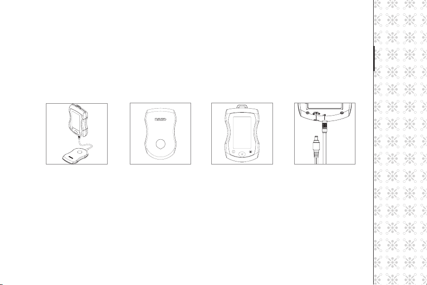
Components
Sherlock Detector Sensor Module Screen Module
AC Adaptor and Power Cord
Sherlock Carrying Case. e carrying case can be attached to the Site~Rite* roll stand basket using the
straps provided on the rear of the carrying case.
4
Detector with AC
adapter inserted
Page 10
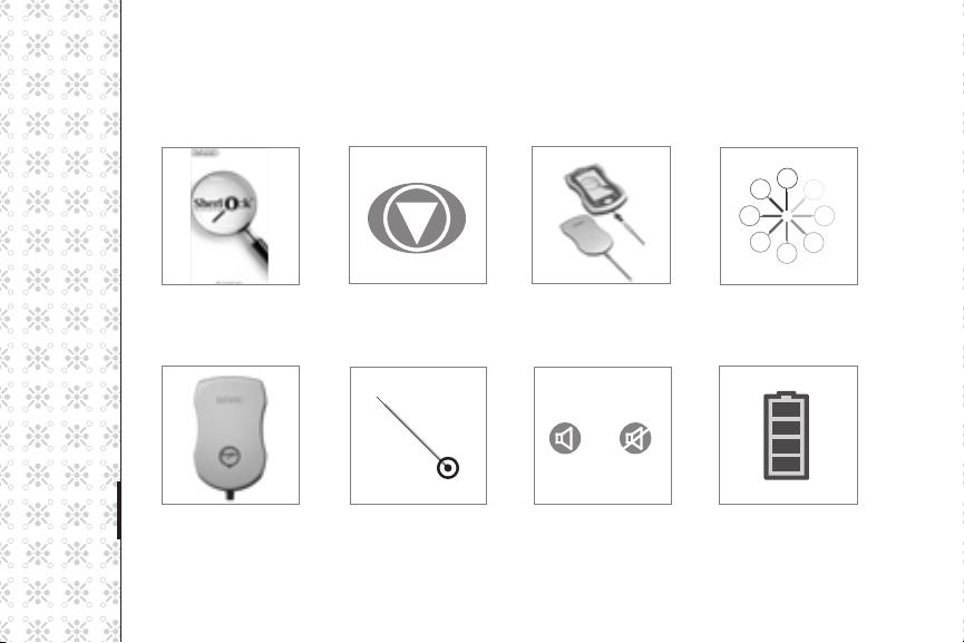
Display Screen Information
Start-up Screen Start/Calibration Sensor Module Unplugged Calibrating
Ready for Use Stylet Tip Position Mute/No Mute Battery Charge
5
Page 11
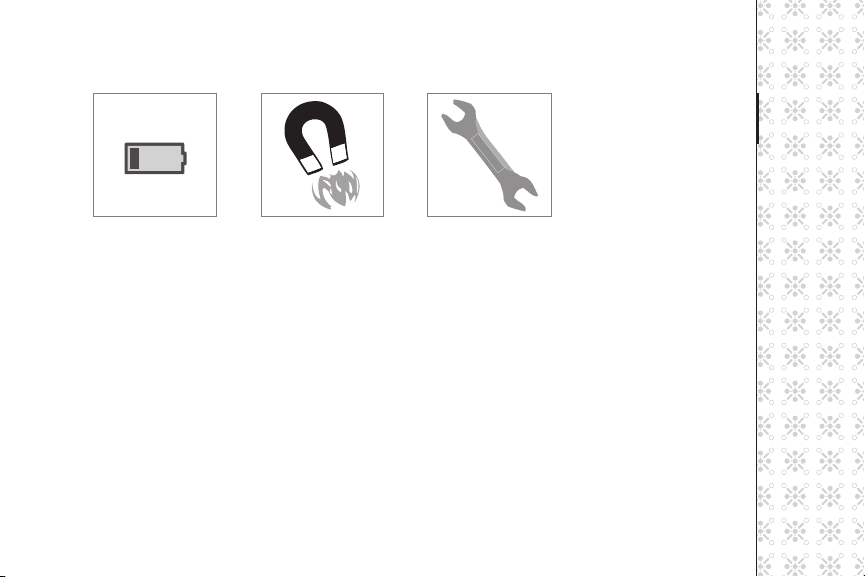
Low Battery Magnetic Error Repair Needed
3] Indications For Use
e Sherlock Tip Location System (TLS) detector quickly locates and con rms the position of specially
designed, magnet-tipped Peripherally Inserted Central Catheters [PICCs] and Central Venous Catheters
[CVCs] during initial placement. is device may be used by appropriate caregivers in hospitals, long-term
care facilities or home-care settings.
e Sherlock Tip Location System (TLS) detector provides rapid feedback to the caregiver, but was not
designed to replace conventional methods of placement veri cation. Users are urged to con rm correct
placement according to their established institutional protocol and clinical judgment.
6
Page 12

Note: Use of the Sherlock detector is not recommended with catheters that are not speci cally marked
with the Sherlock catheter tip location system trademark and logo, and manufactured by Bard
Access Systems.
4] Warnings / Precautions
Warnings
DANGER: Do not operate the Sherlock detector in the presence of ammable anesthetic
gases – potential explosion hazard.
Precautions
1 - Federal [U.S.A.] law restricts this detector to sale by or on the order of a physician.
2 - Do not submerge the Sherlock sensor or screen in water or other uids.
3 - Do not attempt to sterilize.
4 - e Sherlock sensor and screen must only be used with Bard Access Systems central venous
catheters that contain the Sherlock stylet.
5 - Wired undergarments may a ect the performance of the Sherlock detector.
6 - Avoid contact between the Sherlock sensor module and strong magnetic elds such as MRIs.
7
Page 13

7 - Do not allow any ferromagnetic objects, e.g. metal instruments, watches, jewelry, electronic
detectors, metal bedrails, etc. to be within 30 cm [12 in] of the Sherlock sensor module once the
calibration process is complete. e sensor module may detect the item’s magnetic eld, which
will interfere with the sensor module’s ability to accurately locate the Sherlock stylet tip.
8 - Active electric motor driven equipment, such as pumps should not be used within
ve feet of the Sherlock sensor module during the catheter insertion procedure as they may
interfere with Sherlock's detection of the stylet.
9 - Temporary disruption of the cardiac rhythm device may occur if the Sherlock tip location stylet
passes within 1 cm of the cardiac rhythm device. Use care if placing the Sherlock tip location stylet
on the same side as the cardiac rhythm device.
Note: A nal con rmation of the catheter tip location must still be determined based on the
protocol of the facility.
Possible Complications
- Ferromagnetic interference
- Temporary disruption of cardiac rhythm devices
- Sensor or screen malfunction
Complications associated with central venous catheter placements. For possible complications
consult Bard Access Systems catheter “Instructions for Use”.
8
Page 14

5] Service and Information
For questions regarding service please call Bard Access Systems at 1-800-545-0890.
e Sherlock detector contains no user serviceable parts. Only Bard Access Systems authorized service
personnel should attempt to service this equipment.
Note: Servicing of the battery pack or the combination AC adaptor must be performed only by Bard
Access Systems authorized service personnel.
e following actions void the warranty of the Sherlock detector:
- Opening or attempting to open the Sherlock sensor or screen modules.
- Removal of system labels by anyone other than by Bard Access Systems authorized service personnel.
- Opening or attempting to open the Sherlock battery pack or the combination AC adaptor.
- Connecting the Sherlock screen module to any power source other than the Sherlock combination
AC adaptor and battery pack.
- Connecting the Sherlock screen module to any AC adaptor other than the one provided with
the detector.
- Connecting the Sherlock detector to any unauthorized accessory.
9
Page 15

6] Instructions For Use
Note: Prior to use of the Sherlock detector, the operator must read these instructions and be
thoroughly familiar with the Sherlock detector operation.
Step 1: Patient Preparation
1 - Ensure your Bard Access Systems catheter kit contains the Sherlock stylet.
2 - Inspect the Sherlock screen and sensor modules for damage prior to use. If damage to the
Sherlock detector is noted, do not use it.
3 - Ensure there is su cient battery life to perform procedure prior to beginning procedure. If not,
the device can be used with the AC adapter by plugging the AC adapter into the screen module.
4 - Lower the bedrail on the insertion side.
5 - Position the patient for the procedure.
6 - Open the sensor holder pouch and insert the sensor.
10
Page 16

7 - Secure the sensor in the pouch using the adhesive tabs on the bottom
of the pouch.
8 - Identify desired location on the patient’s body to place the Sherlock sensor.
a - e Sherlock sensor may be placed over the right intercostal space to
track catheter tip movement, detect catheter tip orientation, and sense
the catheter tip end point relative to this external landmark.
Note: e external measurement can never exactly represent the internal venous anatomy.
Consider patient body habitus, making adjustments in catheter length for extremes in body
weight and / or height.
b - Alternatively, the Sherlock sensor may be placed along the right clavicle to
track catheter movement and detect catheter tip orientation
during placement.
9 - Follow facility protocols for locating the anatomical landmark on the patient’s chest.
Note: e Sherlock sensor will work for either le -sided or right-sided placement procedures.
11
Page 17

Note: Although the Sherlock sensor may be used external to the patient’s gown, for best results,
the pouched sensor module should be placed directly on the patient’s skin. To provide secure
attachment, clean skin if necessary. Excessive hair should be removed if possible.
10 - Remove the adhesive backing from the back of the sensor holder pouch.
11 - Place the sensor module over the selected anatomical landmark on the patient. Use the Sherlock
logo on the lower third of the sensor module to mark the anatomical landmark. A picture of
the sensor module with the Sherlock logo is displayed on the screen module and can be used as
a reference during the catheter placement procedure.
Note: e sensor module’s cable should be directed towards the patient’s feet.
12 - Securely attach the sensor module to the patient with adhesive side down. Press down on the
Sherlock sensor module rmly to allow for the adhesive strips to adhere.
Note: Do not move the Sherlock sensor module a er it is secure. Best results will be achieved if
the patient remains still and the sensor module is not placed on open wounds, over bandages,
drapes, gowns, or other coverings.
12
Page 18

13 - Connect the Sherlock sensor module cable to the Sherlock screen module. To connect the cable
to the screen module align the red dot on both the cable connector and the screen module
connector and gently push. You will feel the connectors snap together.
14 - Place the Sherlock screen module outside the sterile eld where the screen module may be
conveniently and easily viewed by the user during catheter placement.
15 - Set-up sterile eld.
16 - Prepare the insertion site with ChloraPrep One-Step Applicator or according to institutional policy
using sterile technique.
13
Page 19

Step 2: Sherlock Device Preparation
1 - Power on the Sherlock detector by pressing and holding the on-o
button. While the detector is powering on, the screen module will ash
the Sherlock logo and the screen will illuminate.
2 - Allow the Sherlock detector to complete its power on cycle. is cycle
will take approximately 5 seconds. e screen will display the
“Start/Calibration” icon when the system is ready for use.
Note: If the indicator for low battery [ ashing battery icon] is displayed, battery power is low
and the AC adaptor should be used during catheter placement by plugging the AC adapter into
the screen module. e Sherlock detector can be used for approximately 20 minutes on battery
power a er the low battery indicator is rst displayed.
Step 3: Catheter Placement and Determination of Tip Position
1 - Press the “Start/Calibration” button on the Sherlock screen module.
Note: During the calibration sequence ensure that the Bard Access Systems stylet is at least 30
cm [12 in] away from the sensor module.
14
Page 20

Note: If the unplugged sensor module is displayed, plug the sensor module into
the screen module. Press the “Start/Calibration” button to begin calibration.
2 - e Sherlock detector will calibrate itself. During the calibration process the
screen will display a rotating magnifying glass. When the Sherlock detector
is ready for use, the sensor module outline is displayed.
3 - Once the calibration process is complete, do not reposition the patient [e.g.
move patient up or down, elevate or lower bed, raise or lower bedrails, etc.].
Ask the patient to remain still.
Caution: Do not allow any ferromagnetic objects, e.g. metal instruments, watches, jewelry,
electronic detectors, metal bedrails, etc. to be within 30 cm [12 in] of the Sherlock sensor
module once the calibration process is complete. e sensor module may detect the item’s
magnetic eld, which will interfere with the sensor module’s ability to accurately locate the
Sherlock stylet tip.
Caution: Active electric motor driven equipment, such as pumps, should not be used within
ve feet of the Sherlock sensor module during the procedure. e Sherlock detector should
never be used in or near a room containing MRI equipment.
15
Page 21

4 - Remove and discard skin prep gloves.
5 - Continue patient preparation and establish sterile eld according to catheter instructions for use
and facility protocol.
6 - Insert the catheter with the preloaded Sherlock stylet according to the Bard Access Systems
catheter’s instructions for use.
Note for open-ended, polyurethane catheters: Follow the instructions for use in the Bard Access
Systems Sherlock-labeled catheter kits to assure the tip of the Sherlock stylet is not trimmed and is
within 1 cm of the end of the catheter prior to catheter insertion. If the magnetic tip of the Sherlock
stylet is accidentaly removed by trimming, the stylet cannot be detected by the Sherlock detector.
7 - As the stylet tip approaches the Sherlock sensor module, an icon indicates where the stylet tip is
located in relation to the sensor module. e location icon is displayed in its relative position to
the sensor module, as if viewed from above and through the sensor module into the patient.
Note: e Sherlock detector can detect the Sherlock magnet-tipped stylet while it is
still outside the physical perimeter of the sensor module. In this case, the stylet
location icon will be an arrow at the edge of the display, pointing towards the
location of the approaching stylet.
16
Page 22

Note: When the stylet tip is positioned underneath the Sherlock sensor module, the
stylet location icon changes to a representation of the stylet tip, and indicates the
location and orientation of the stylet tip beneath the sensor module.
8 - In the event the stylet icon does not appear on the Sherlock screen module a er the
pre-measured length of the catheter has been inserted, pull the catheter back 20-25 cm and
reinsert. If the stylet icon is still not visible a er attempted reinsertion, the device may need to
be recalibrated.
a - Withdraw the catheter at least 30 cm; this may require removing the catheter from the
introducer sheath.
b - Press the “Start/Calibration” button to begin calibration.
c - Once the calibration process is complete, do not reposition the patient. Ask the patient to
remain still.
d - Don a new pair of sterile gloves.
e - Reinsert the catheter and stylet. As the stylet tip approaches the Sherlock sensor module,
the cursor will indicate where the stylet tip is located in relation to the sensor module.
9 - If the icon does not appear on the Sherlock screen module a er attempted recalibration and
reinsertion, the Sherlock sensor module can be placed along the clavicle to provide feedback on
the catheter path during placement.
17
Page 23

a - Retract the catheter so that the tip of the stylet is at least 30 cm [12 in] away from the sensor module.
is may require removing the catheter from the introducer sheath.
b - Remove sterile drapes from patient’s chest while maintaining sterile insertion site.
c - Remove the sensor holder pouch from the patient and remove the sensor module from the pouch.
d - Dispose of the sensor holder pouch in accordance with facility policy.
e - Place the sensor in the second sensor holder pouch provided in catheter kits containing the
Sherlock stylet. Secure the sensor in the pouch using the adhesive tabs on the bottom of the pouch.
f - Remove the adhesive backing from the back of the sensor holder pouch.
g - Place the sensor module over the clavicle on the same side as attempted catheter placement.
h - Securely attach the sensor module to the patient with adhesive side down. Press down on the
Sherlock sensor module rmly to allow for the adhesive strips to adhere.
i - Press the “Start/Calibration” button to begin calibration.
j - Once the calibration process is complete, do not reposition the patient. Ask the patient to
remain still.
k - Don a new pair of sterile gloves.
l - Re-establish sterile eld, according to catheter instructions for use and facility protocol.
m - Advance the catheter and stylet. As the stylet tip approaches the Sherlock sensor module, the
cursor will indicate where the stylet tip is located in relation to the sensor module.
18
Page 24

n - Monitor the location of the stylet tip icon along the Sherlock sensor module.
e icon will show the direction of the catheter as it progresses through
the venous system. Adjust catheter position as necessary until the icon
shows the catheter progressing down into the SVC.
10 - As the stylet approaches the Sherlock logo located at the lower third of the
sensor module, an audible / visible indicator provides location feedback to
the clinician.
Note: To mute the detector: Press the mute button. You cannot adjust the volume of the detector.
Note: e stylet icon is displayed in its relative position to the sensor module as if viewed
from above the sensor module.
11 - When the stylet icon is in the desired position, the Sherlock detector can be powered down or
remain operational for the remainder of the procedure.
12 - Complete catheter insertion and securement procedure according to the catheter instructions
for use and facility protocol.
13 - Remove the sterile eld.
19
Page 25

14 - Remove the sensor holder pouch and adhesive.
15 - Open the sensor holder pouch and remove the Sherlock sensor module.
16 - Dispose of the sensor holder pouch in accordance with facility policy.
Note: e sensor holder pouch is for single-use only.
17 - Follow facility protocol to con rm nal catheter tip location.
20
Page 26

7] Troubleshooting
Problem Solution
e Sherlock detector won’t power on. Press and hold the power button for at least 3 seconds
e Sherlock detector won’t power on, or powers on
but immediately turns o .
When the Start/Calibration button is pressed, the
Attach Sensor Module screen is displayed.
When the Start/Calibration button is pressed, the
Magnetic Field Error screen is displayed.
Attach the AC adaptor to both power the Sherlock during the
procedure, and to charge the battery. Plug the AC adapter into the
screen module.
Make sure the sensor module cable is inserted fully and correctly into
the display module.
Press the Start/Calibration button to begin again.
If the Attach Sensor Module screen still appears, contact Bard
Access Systems customer service at 1-800-545-0890.
Lower bed rails.
Make sure all metal objects are at least 30 cm [12 in] from the
sensor modul e.
Make sure the sensor module pouch is rmly attached and ask the
patient to remain still during the calibration process and during
catheter insertion.
Press the Start/Calibration button to begin again.
21
Page 27

Problem Solution
During catheter insertion, the Magnetic Field Error
screen is displayed.
e Internal Error screen is displayed during Sherlock
power-on, or at any other time while in use.
Sensor does not detect stylet. Check stylet to verify magnetic tip has not been trimmed o .
Make sure no metal objects have been brought near to the
sensor modul e
Make sure the sensor module pouch is rmly attached and ask
the patient to remain still during catheter insertion.
Press the Start/Calibration button to begin again.
Press and hold the power button to turn o the system.
Power the system back on and if the Internal Error screen is
no longer displayed, proceed as normal.
If the Internal Error screen is again displayed, contact Bard
Access Systems customer service at 1-800-545-0890.
Check stylet to insure tip is within one cm of catheter end.
Reposition sensor to clavicle as described in Step 3 -9, page 18.
22
Page 28

8] Maintenance
1 - Wipe the Sherlock display and sensor modules a er each use according to facility protocol.
Caution: Do not submerge the Sherlock screen or sensor modules in water or other uids or
attempt to sterilize. Do not open or attempt to open the Sherlock modules as they are
not user serviceable. Contact Bard Access Systems for service returns.
2 - Battery Life
a - e runtime of a fully charged battery is approximately 4 hours.
b - If the Sherlock sensor module does not sense a Sherlock stylet a er 30 minutes, the Sherlock
detector will automatically power o .
c - Low battery charge is indicated on the screen module by the ashing battery icon.
d - When battery power is low, the AC adaptor can be used during catheter placement.
e - e Sherlock detector can be used for approximately 20 minutes a er the low battery power
indicator ( ashing battery icon) is rst displayed.
f - To recharge the battery fully, connect the AC adaptor to the Sherlock screen module. e
battery power indicator on the screen module will display bars to represent the amount
of charge the battery received. To fully recharge the battery, plan on a minimum of 3 hours.
23
Page 29

To store the Sherlock device: e Sherlock sensor and screen module may be placed in the carrying case
for secure transport. e detector should be operated at temperatures from 10° C (50° F) to 40° C (104°
F). e Sherlock detector should be stored at temperatures from 0° C (32° F) to 60° C (140° F). If the
Sherlock detector is stored at temperatures outside of the operating range, the detector should be allowed
to stabilize for two hours prior to operation in the operating temperature range.
9] Speci cations
1 - Power source: Lithium polymer battery or 120V AC power supply
2 - Usable runtime of a fully charged battery under continuous use: Approximately 4 hours
3 - Controls:
a - Power – ON/OFF button
b - Mute/No Mute button
c - Start – Start/Calibration button
24
Page 30

4 - Display Screen Information:
a - Start-up Screen
b - Start/Calibration
c - Calibrating
d - Ready for Use
e - Stylet Tip Position
f - Mute/No Mute
g - Battery Charge
h - Low Battery
i - Magnetic Error
j - Internal Error
5 - Cables:
a - AC adaptor – power source for the Sherlock detector
b - Extension cable – connects the sensor module with the screen module. It is detachable from
the screen module
25
Page 31

Appendix A: Sherlock Tip Location System - Electromagnetic Compatibility
A.1 COMPLIANCE AND WARNINGS
e BARD Sherlock Tip Location System has been tested to and found compliant with the requirements
of IEC 60601-1-2:2001
Wa rn i n g
e use of other accessories other than those speci ed may result in increased emissions or decreased
immunity of the equipment
Verify correct operation if the Sherlock TLS is to be used adjacent to other equipment.
26
Page 32

A.2 ELECTROMAGNETIC EMISSIONS
Guidance and manufacturer’s declaration – Electromagnetic Emissions
e Sherlock detector is intended for use in the electromagnetic environment speci ed below. e customer or the user
of the Sherlock detector should assure that it is used in such an environment.
Emissions Test Compliance Electromagnetic environment - guidance
RF emissions
CISPR 11
RF emissions Class A e Sherlock detector is suitable for use in all establishments other
Harmonic emissions
IEC 61000-3-2
Vol ta ge uctuations/
icker emissions
IEC 61000-3-3
Group 1 e Sherlo ck detector uses RF energy only for its internal function.
Class A
Complies
erefore, its RF emissions are very low and not likely to cause any
interference in nearby electronic equipment.
than domestic and those directly connected to the public low-voltage power supply network that supplies buildings used for
domestic purposes.
27
Page 33

Essential Performance
e Sherlock detector maintains safe and e ective performance of the catheter tracking function when
operated in the electromagnetic environment speci ed in Tables A-2 through A-4.
Limitations A ecting Immunity to Electromagnetic Disturbances
e level of protection from electromagnetic disturbances is limited by several factors, including
requirements for patient safety isolation, and maintenance of adequate signal-to-noise ratios for
processing of magnet tipped stylet signals.
A.3 ELECTROMAGNETIC IMMUNITY
Guidance and manufacturer’s declaration – electromagnetic immunity
e Sherlock detector is intended for use in the electromagnetic environment speci ed below. e customer or the user
of the Sherlock detector should assure that it is used in such an environment.
Immunity Test IEC 60601
test level
Electrostatic discharge
(ESD) IEC 61000-4-2
Electrical fast
transient/burst
IEC 61000-4-4
28
± 6 kV contact
± 8 kV air
± 2 kV for power
supply lines
± 1 kV for
input/output lines
Compliance Level Electromagnetic
environment - guidance
± 6 kV contact
± 8 kV air
± 2 kV for power
supply lines
± 1 kV for
input/output lines
e Sherlock detector is suitable for
use in a dry environment.
Mains power quality should be that
of a typical commercial or
hospital environment.
Page 34

Immunity Test IEC60601
Compliance Level Electromagnetic
test level
Surge
IEC 61000-4-5
Voltage dips, short
interruptions and
voltage variations on
power supply input
lines
IEC 61000-4-11
Power Frequency
(50/60 Hz)
magnetic eld
IEC 61000-4-8
Note: UT is the a.c. mains voltage prior to application of the test level.
± 1 kV di erentia mode
± 2 kV common mode
< 5 % UT (> 95 % dip in
UT for 0,5 cycle)
40 % UT (60 % dip in
UT for 5 cycles)
70 % UT (30 % dip in
UT for 25 cycles)
< 5 % UT (> 95 % dip in
UT for 5 seconds)
3 A/m 3 A/m Power frequency magnetic elds
± 1 kV di erential mode
± 2 kV common mode
< 5 % UT (> 95 % dip in
UT for 0,5 cycle)
40 % UT (60 % dip in
UT for 5 cycles)
70 % UT (30 % dip in
UT for 25 cycles)
< 5 % UT (> 95 % dip in
UT for 5 seconds)
environment - guidance
Mains power quality should be that
of a typical commercial or
hospital environment.
Mains power quality should be that
of a typical commercial or hospital
environment. If the user of the
Sherlock detector requires continued
operation during power mains
operation, it is recommended that the
Sherlock detector shall be powered
from an uninterruptible power supply
or battery.
should be at levels characteristic of a
typical location in a typical
commercial or hospital environment.
29
Page 35

Guidance and manufacturer’s declaration – electromagnetic immunity
e Sherlock detector is intended for use in the electromagnetic environment speci ed below. e customer or the user
of the Sherlock detector should assure that it is used in such an environment.
Emissions Test Compliance Compliance Level Electromagnetic environment - guidance
Portable and mobile RF communications
equipment should be used no closer to any
part of the Sherlock detector, including cables, than the
recommended separation distance calculated from the
equation applicable to the frequency of the transmitter.
Recommended separation distance
Conducted RF
IEC 61000-4-6
3 Vrms
150 kHz to 80
MHz
3 V/m
d = 1,2√P
d = 1,2√P 80 MHz to 800 MHz
d = 2,3√P 800 MHz to 2,5 GHz
30
Page 36
Emissions Test Compliance Compliance Level Electromagnetic environment - guidance
Radiated RF
IEC 61000-4-3
NOTE 1 At 80 MHz and 800 MHz, the higher frequency range applies.
NOTE 2 ese guidelines may not apply in all situations. Electromagnetic propagation is a ected by absorption and re ection from
structures, objects and poles
a
Field strengths from xed transmitters, such as base stations for radio (cellular/cordless) telephones and land mobile radios,
amateur radio, AM and FM radio broadcast and TV broadcast cannot be predicted theoretically with accuracy. To assess the electromagnetic environment due to xed RF transmitters, an electromagnetic site survey should be considered. If the measured eld
strength in the location in which the
detector should be observed to verify normal operation. If abnormal performance is observed, additional measures may be
necessary, such as reorienting or relocating the
b
Over the frequency range 150 kHz to 80 MHz, eld strengths should be less than 3 V/m.
3 V/m
80 MHz to 2,5
GHz
3 V/m where P is the maximum output power rating of the
transmitter in watts (W) according to the transmitter
manufacturer and d is the recommended separation
distance in meters (m).
Field strengths from xed RF transmitters, as determined by an electromagnetic site surveya should be less
than the compliance level in each frequency rangeb.
Interference may occur in the vicinity of
equipment marked with the following symbol.
Sherlock detector is used exceeds the applicable RF compliance level above, the Sherlock
Sherlock detector.
31
Page 37

A.4 Recommended separation distances
Recommended separation distances between portable and mobile RF communications equipment and the Sherlock detector
e Sherlock
trolled. e customer or the user of the Sherlock detector can help prevent electromagnetic interference by maintaining a
minimum distance between portable and mobile RF communications equipment (transmitters) and the Sherlock detector
system as recommended below, according to the maximum output power of the communications equipment.
Rated maximum output
power of transmitter (W)
0,01 0,12 0,12 0,23
0,1 0,38 0,38 0,73
1 1,2 1,2 2,3
10 3,8 3,8 7,3
100 12 12 23
For transmitters rated at a maximum output power not listed above, the recommended separation distance d in meters (m) can be
estimated using the equation applicable to the frequency of the transmitter, where P is the maximum output power rating of the
transmitter in watts (W) according to the transmitter manufacturer.
NOTE 1: At 80 MHz and 800 MHz, the separation distance of the higher frequency range applies.
NOTE 2: ese guidelines may not apply in all situations. Electromagnetic propagation is a ected by absorption and re ection from
32
structures, objects and people.
detector is intended for use in an electromagnetic environment in which radiated RF disturbances are con-
Separation distance according to the frequency of transmitter (m)
150 kHz to 80 MHz
d = 1,2√P
80 to 800 MHz
d = 1,2√P
800 MHz to 2,5 GHz
d = 2,3√P
Page 38

Equipment operating in close proximity may emit strong electromagnetic or radio frequency interference
(RFI) which could a ect the performance of this device. RFI may result in improper device operation or
failure to detect a correctly placed catheter. Avoid operating the device near cauterizers, diathermy
equipment, cellular phones, or other portable and mobile RF communications equipment. Maintain
equipment separation of at least 1.2 m (4 ) and do not rapidly key radios on and o . Contact a technical
support representative if assistance is required.
Possible electrical interference.
Using cables, battery chargers, or accessories not speci ed for use with this device may result in increased
emissions or decreased resistance to electromagnetic interference, which could a ect the performance of
this device or of equipment in close proximity. Use only parts and accessories speci ed in these operating
instructions.
Safety Information
WA R N I N G S !
Possible device shutdown.
Always check to make sure the battery is properly charged prior to the start of any procedure. Recharge
the battery a er each use and when the device displays a low battery warning.
33
Page 39

Possible improper device performance.
Using other manufacturers’ cable, battery, or battery charger may cause the device to perform
improperly and invalidates the safety agency certi cation. Use only the accessories speci ed in these
Operating Instructions.
Safety risk and possible equipment damage.
e Sherlock detector and accessories contain ferromagnetic materials. As with all ferromagnetic
equipment, these products must not be used in the presence of the high magnetic eld created by a
Magnetic Resonance Imaging (MRI) device. e high magnetic eld created by an MRI device will attract
the equipment with a force su cient to cause death or serious personal injury to persons between the
equipment and the MRI device. is magnetic attraction may also damage the equipment. Consult the
MRI manufacturer for more information.
CAUTION!
Possible equipment damage.
is device may be damaged by mechanical or physical abuse such as immersion in water or dropping the
device. If the device has been abused, remove it from use and contact the manufacturer.
34
Page 40

Safety risk and possible equipment damage.
e Sherlock detector Tip Location System AC adaptor and power cord is speci cally designed for use with
the Sherlock detector. Use of any other power supply may cause damage to the system, or harm to the
operator or patient. Use only the Sherlock detector AC adaptor, BARD PN 9760062, and the Sherlock
Power Cord, BARD PN 9760065 with the Sherlock detector Tip Location System.
35
Page 41
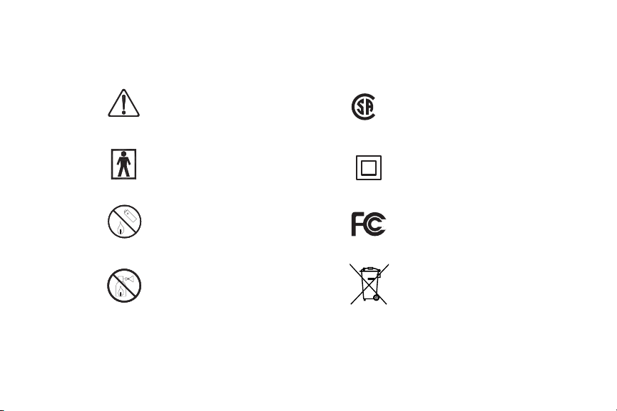
Warning: Refer to
Manual Before Use
C US
202071
Canadian Standards
®
Association
BF Type Equipment
Do Not Dispose of
Battery Pack In Fire
Do not operate in the presence
of flammable anesthetics.
Class II Insulation
CLASS II
Federal Communications
Commission
Do not dispose with
ordinary municipal waste
Page 42

Prescription Only
75%
Operating Humidity
Battery Pack
30%
95%
o
C
60
o
C
0
o
C
10
Storage Temperature
Parameters
o
C
40
Operating Temperature
Parameters
20%
Storage Humidity
Latex Free
Page 43

*Bard, Sherlock, and Site~Rite are trademarks and/or registered trademarks of C. R. Bard, Inc. or an a liate.
e information contained in this document is subject to change without notice or obligation. is document
contains proprietary information that is protected by copyright. No part of this document may be photocopied,
reproduced, or translated without the expressed written consent of Bard Access Systems.
Sherlock* Tip Location Detector Manufactured for:
Bard Access Systems
Salt Lake City, UT 84116
U.S .A .
(801) 595-0700
Customer Service: (800) 545-0890
Technical/Clinical Information: (800) 443-3385
Fax: (801) 595-4948
www.bardaccess.com
www.DiscoverSherlock.com
Page 44

Page 45

Page 46

 Loading...