

Bard SH611D Installation Instructions Manual

INSTALLATION INSTRUCTIONS
WALL MOUNTED
PACKAGE HEAT PUMPS
Model
SH611D
Bard Manufacturing Company
Bryan, Ohio 43506
Since 1914...Moving ahead just as planned.
Manual : 2100-414C
Supersedes: 2100-414B
File: Volume III Tab 17
Date: 05-06-05
© Copyright 2004

CONTENTS
Getting Other Information and Publications
For More Information ............................................... 1
Wall Mount General
Heat Pump Wall Mount Model Nomenclature ....... 2
Shipping Damage ................................................. 4
General .............................................................. 4
Duct Work ............................................................. 4
Filters .............................................................. 5
Fresh Air Intake ..................................................... 5
Condensate Drain – Evaporator ........................... 5
Installation Instructions
Wall Mounting Information .................................... 6
Mounting the Unit .................................................. 6
Wiring – Main Power ........................................... 11
Wiring – Low Voltage Wiring ............................... 11
Compressor Cutoff Thermostat and
Outdoor Thermostats .......................................... 14
Units Equipped with 1F93-380 Thermostat......... 14
Units Equipped with T8511 Thermostat .............. 14
Low Voltage Connections ................................... 15
Start Up
Important Installer Note....................................... 16
Crankcase Heaters ............................................. 16
High Pressure Switch ......................................... 16
Three Phase Scroll Compressor Start Up........... 16
Phase Monitor ..................................................... 17
Service Hints ....................................................... 17
Sequence of Operation ....................................... 17
Pressure Service Ports ....................................... 17
Defrost Cycle ...................................................... 18
Troubleshooting
Solid State Heat Pump Control
Troubleshooting Procedure................................. 19
Checking Temperature Sensor
Outside Unit Circuit ............................................. 20
Temperature vs. Resistance of Temperature ...... 20
Fan Blade Setting Dimensions ........................... 21
Removal of Fan Shroud ...................................... 21
Refrigerant Charge ............................................. 21
Pressure Tables .................................................. 22
Figures
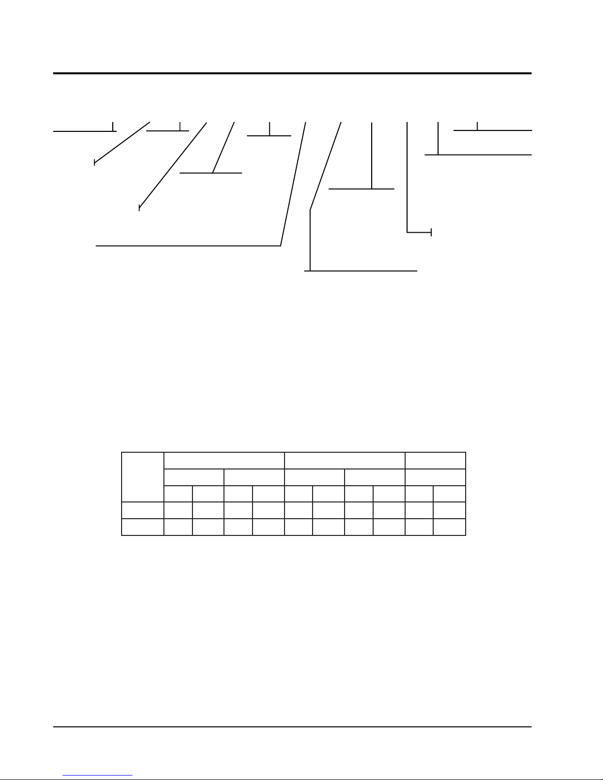
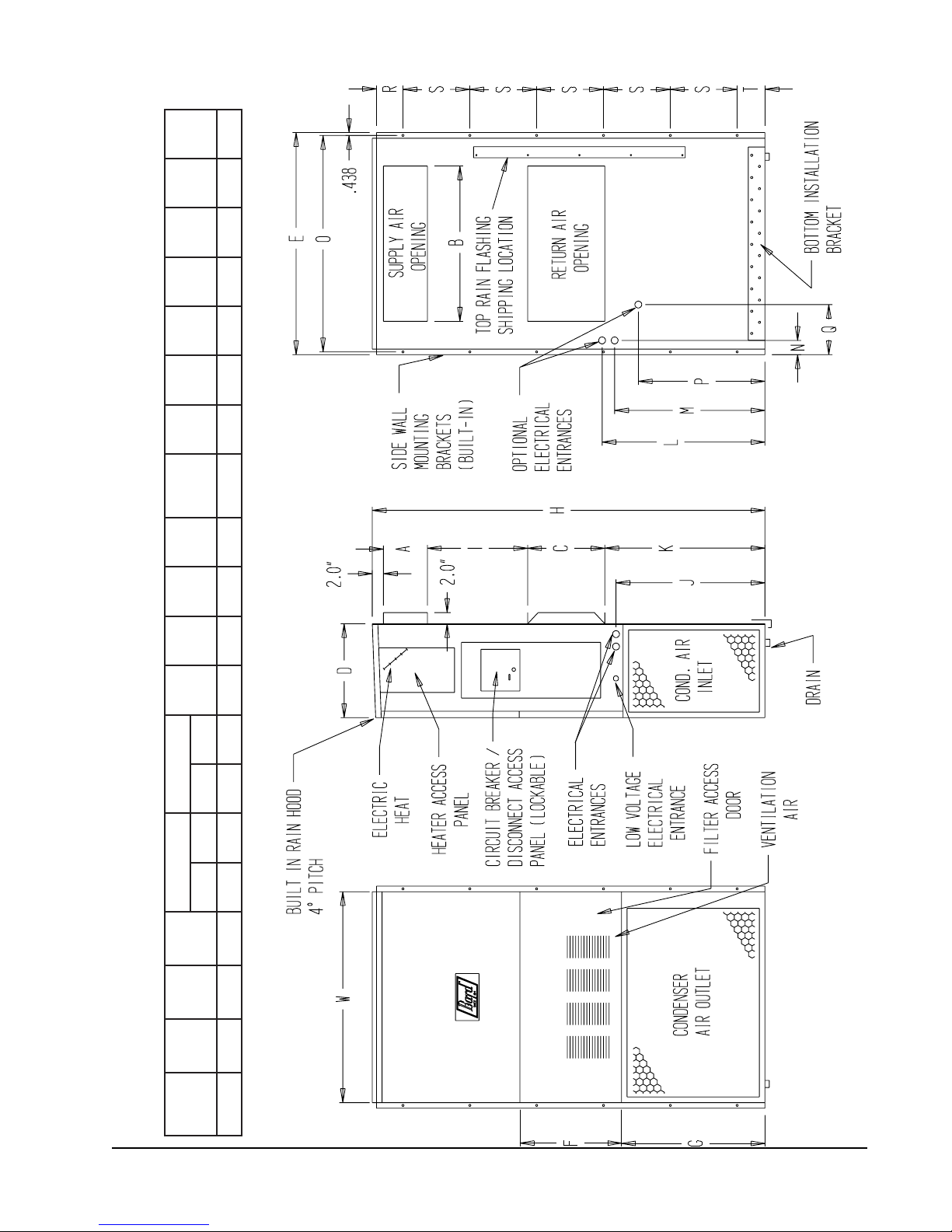
Figure 1 Unit Dimensions .................................. 3
Figure 2 Fresh Air Damper Assembly ................ 5
Figure 3 Mounting Instructions .......................... 7
Figure 4 Electric Heat Clearance ....................... 8
Figure 5 Wall Mounting Instructions................... 9
Figure 6 Wall Mounting Instructions................... 9
Figure 7 Common Wall Mounting Installations . 10
Figure 8 Wiring with CS2000A Monitor ............ 12
Figure 9 Wiring with Programmable Themostat 13
Figure 10 Compressor Cutoff and Outdoor
Thermostat Wiring ............................. 14
Figure 11 Start Up Procedure Decal .................. 16
Figure 12 Defrost Control Board ........................ 18
Figure 13 Fan Blade Setting .............................. 21
Figure 14 Circuit Diagram Heat Pump
Cooling Mode .................................... 23
Figure 15 Circuit Diagram Heat Pump
Dehumidification Mode ...................... 23
Tables
Table 1 Electric Heat Table ................................ 2
Table 2 Electrical Specifications ........................ 4
Table 3 Thermostat Wire Size ......................... 11
Table 4 Wall Thermostat and
Subbase Combinations....................... 15
Table 5 Troubleshooting .................................. 19
Table 6 Fan Blade Dimensions........................ 21
Table 7 Refrigerant Charge ............................. 21
Table 8 Rated CFM and Rated ESP ............... 21
Table 9 Indoor Blower Performance ................ 21
Table 10 Maximum ESP of Operation ............... 21
Table 11 Pressure Table - Cooling .................... 22
Table 12 Pressure Table - Heating .................... 22

Getting Other Information and Publications
These publications can help you install the air
conditioner or heat pump. You can usually find these at
your local library or purchase them directly from the
publisher. Be sure to consult current edition of each
standard.
National Electrical Code ...................... ANSI/NFPA 70
Standard for the Installation .............. ANSI/NFPA 90A
of Air Conditioning and
Ventilating Systems
Standard for Warm Air ...................... ANSI/NFPA 90B
Heating and Air
Conditioning Systems
Load Calculation for ............................ACCA Manual J
Residential Winter and
Summer Air Conditioning
Duct Design for Residential .............. ACCA Manual D
Winter and Summer Air Conditioning
and Equipment Selection
FOR MORE INFORMATION, CONTACT
THESE PUBLISHERS:
ACCA Air Conditioning Contractors of America
1712 New Hampshire Ave. N.W.
Washington, DC 20009
Telephone: (202) 483-9370
Fax: (202) 234-4721
ANSI American National Standards Institute
11 West Street, 13th Floor
New York, NY 10036
Telephone: (212) 642-4900
Fax: (212) 302-1286
ASHRAE American Society of Heating Refrigerating,
and Air Conditioning Engineers, Inc.
1791 Tullie Circle, N.E.
Atlanta, GA 30329-2305
Telephone: (404) 636-8400
Fax: (404) 321-5478
NFPA National Fire Protection Association
Batterymarch Park
P.O. Box 9101
Quincy, MA 02269-9901
Telephone: (800) 344-3555
Fax: (617) 984-7057
Manual 2100-414C
Page 1
WALL MOUNT GENERAL INFORMATION
HEAT PUMP WALL MOUNT MODEL NOMENCLATURE
SH 61 1 D A 10 X X X X X B
MODEL NUMBER
CAPACITY
61 - 5 Ton
DEHUMIDIFICATION
VENTILATION OPTIONS
X - Barometric Fresh Air Damper (Standard)
B - Blank-off Plate
M - Motorized Fresh Air Damper
V-
Commercial Room Ventilator - Motorized with Exhaust
E - Economizer - Fully Modulating with Exhaust
R-
Energy Recovery Ventilator - Motorized with Exhaust
D - Economizer - Fully Modulating with Exhaust
(For use only with “V” Control Module and
TCS20 DDC Controller)
1
Vent options are without exhaust capability. May require separate field supplied barometric relief in building.
REVISIONS
VOLTS & PHASE
A - 230/208/60/1
B - 230/208/60/3
C - 460/60/3
1
KW
00 – 0 KW
09 – 9 KW
10 – 10 KW
COLOR OPTIONS
X - Beige (Standard)
1 - White
4 - Buckeye Gray
5 - Desert Brown
8 - Dark Bronze
1
FILTER OPTIONS
X - 1 Inch Throwaway (Standard)
W- 1 Inch Washable
P - 2 Inch Pleated
CONTROL MODULES
COIL OPTIONS
X - Standard
1 - Phenolic Coated Evaporator
2 - Phenolic Coated Condenser
3 - Phenolic Coated Evaporator
and Condenser
OUTLET OPTIONS
X - Front (Standard)
TABLE 1
ELECTRIC HEAT TABLE
sledoMAD116HSBD116HSCD116HS
1-0421-8023-0423-8023-064
WKAUTBAUTBAUTBAUTBAUTB
9
01
6.14031432.6300652
7.12006037.81030328.0100703
Manual 2100-414C
Page 2
MIS-1261
BACK VIEW
FIGURE 1
UNIT DIMENSIONS
EFGI J KLMNOPQABCB
ylppuSnruteR
thgieH
H
htpeD
D
htdiW
W
D116HS244/1-228/7-498/7-98/7-928/7-518/7-928/7-34918/5-140361/11-24734/3-442/1-244/1-3348/7-3301
tinU
SIDE VIEWFRONT
VIEW
Manual 2100-414C
Page 3
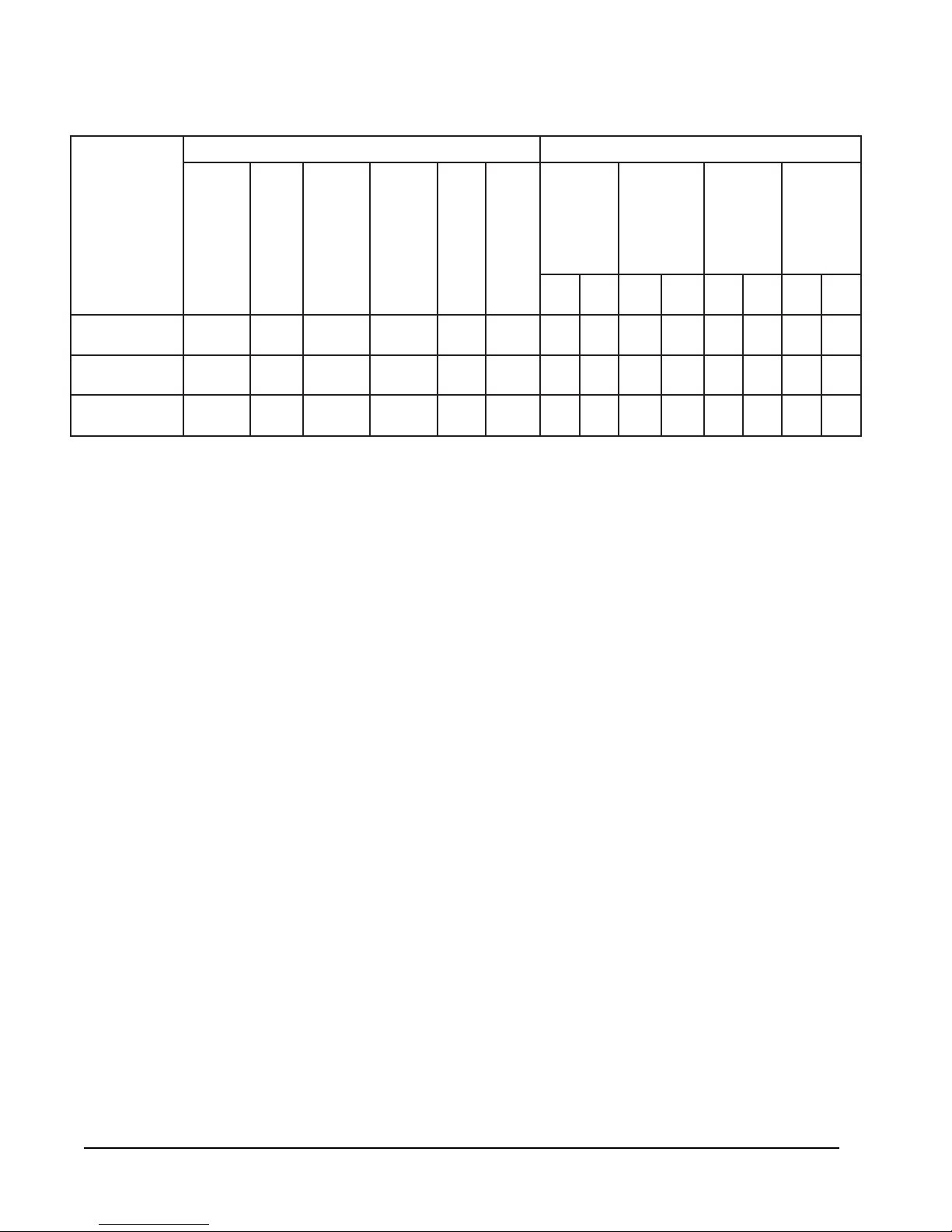
TABLE 2
ELECTRICAL SPECIFICATIONS
TIUCRICELGNIS TIUCRICLAUD
3
.oN
detaR
&stloV
ledoM
Z0A,00AD116HS
01A
Z0B,00BD116HS
90B
Z0C,00C116HS
90C
Maximum size of the time delay fuse or HACR type circuit breaker for protection of field wiring conductors.
1
Based on 75° C copper wire. All wiring must conform to NEC and all local codes.
2
These “minimum Circuit Ampacity” values are to be used for sizing the field power conductors. Refer to
3
the National Electric Code (latest revision), article 310 for power conductor sizing.
more than one field power conductor circuit is run through one conduit, the conductors must be
derated. Pay special attention to note 8 of table 310 regarding Ampacity Adjustment Factors when
more than 3 conductors are in a raceway.
esahP
3-064
3-064
dleiF
rewoP
stiuriC
1-802/032
1
1-802/032
1-802/032
1-802/032
2ro1
1
1
1
1
25
89
63
06
81
23
1
muminiM
tiucriC
yticapmA
06
05
07
52
53
2
mumixaM
lanretxE
roesuF
tiucriC
rekaerB
6
021
3
8
6
8
2
dleiF
rewoP
eriW
eziS
01
eriW
eziS
01
6
01
01
01
01
3
muminiM
tiucriC
dnuorG
yticapmA
.tkC
A
B
---
---
25
25
---
---
---
---
---
---
---
---
CAUTION: When
.tkC
1
mumixaM
lanretxE
roesuF
tiucriC
rekaerB
.tkC
A
B
---
---
06
06
---
---
---
---
---
---
---
---
2
dleiF
rewoP
eziSeriW
.tkC
.tkC
A
B
---
---
6
6
---
---
---
---
---
---
---
---
2
dnuorG
eziSeriW
.tkC
.tkC
.tkC
A
B
---
---
01
01
---
---
---
---
--
---
---
---
SHIPPING DAMAGE
Upon receipt of equipment, the carton should be
checked for external signs of shipping damage. If
damage is found, the receiving party must contact the
last carrier immediately, preferably in writing,
requesting inspection by the carrier’s agent.
GENERAL
The equipment covered in this manual is to be installed
by trained, experienced service and installation
technicians.
The refrigerant system is completely assembled and
charged. All internal wiring is complete.
The unit is designed for use with or without duct work.
Flanges are provided for attaching the supply and return
ducts.
These instructions explain the recommended method to
install the air cooled self-contained unit and the
electrical wiring connections to the unit.
These instructions and any instructions packaged with
any separate equipment, required to make up the entire
air conditioning system should be carefully read before
beginning the installation. Note particularly “Starting
Procedure” and any tags and/or labels attached to the
equipment.
While these instructions are intended as a general
recommended guide, they do not supersede any national
and/or local codes in any way. Authorities having
jurisdiction should be consulted before the installation is
made. See Page 1 for information on codes and
standards.
Size of unit for a proposed installation should be based
on heat loss calculation made according to methods of
Air Conditioning Contractors of America (ACCA). The
air duct should be installed in accordance with the
Standards of the National Fire Protection Association
for the Installation of Air Conditioning and Ventilating
Systems of Other Than Residence Type, NFPA No.
90A, and Residence Type Warm Air Heating and Air
Conditioning Systems, NFPA No. 90B. Where local
regulations are at a variance with instructions, installer
should adhere to local codes.
DUCT WORK
Any heat pump is more critical of proper operating
charge and an adequate duct system than a straight air
conditioning unit. All duct work, supply and return,
must be properly sized for the design air flow
requirement of the equipment. Air Conditioning
Contractors of America (ACCA) is an excellent guide to
proper sizing. All duct work or portions thereof not in
the conditioned space should be properly insulated in
order to both conserve energy and prevent condensation
or moisture damage.
Manual 2100-414C
Page 4
Design the duct work according to methods given by the
Air Conditioning Contractors of America (ACCA).
When duct runs through unheated spaces, it should be
insulated with a minimum of one inch of insulation.
Use insulation with a vapor barrier on the outside of the
insulation. Flexible joints should be used to connect the
duct work to the equipment in order to keep the noise
transmission to a minimum.
A 1/4 inch clearance to combustible material for the
first three feet of duct attached to the outlet air frame is
required. See Wall Mounting Instructions and Figures 3
and 4 for further details.
Ducts through the walls must be insulated and all joints
taped or sealed to prevent air or moisture entering the
wall cavity.
Some installations may not require any return air duct.
A metallic return air grille is required with installations
not requiring a return air duct. The spacing between
louvers on the grille shall not be larger than 5/8 inch.
FRESH AIR INTAKE
All units are built with fresh air inlet slots punched in
the service panel.
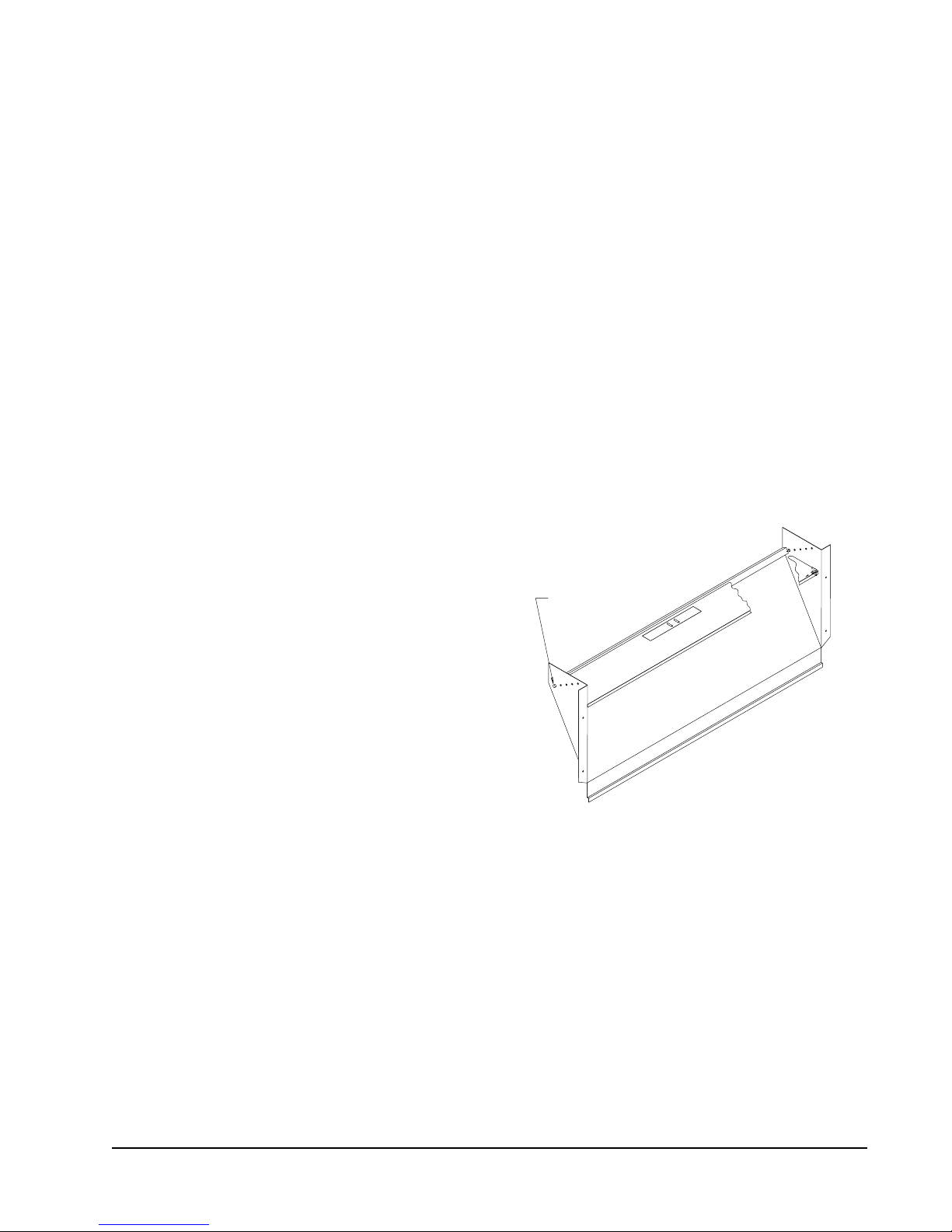
If the unit is equipped with a fresh air damper assembly,
the assembly is shipped already attached to the unit.
The damper blade is locked in the closed position. To
allow the damper to operate, the maximum and
minimum blade position stops must be installed. See
Figure 2.
All capacity, efficiency and cost of operation
information as required for Department of Energy
“Energyguide” Fact Sheets is based upon the fresh air
Blank-off plate in place and is recommended for
maximum energy efficiency.
The blank-off plate is available upon request from the
factory and is installed in place of the fresh air damper
shipped with each unit.
NOTE: If no return air duct is used, applicable
installation codes may limit this cabinet to
installation only in a single story structure.
Any grille that meets with 5/8 inch louver criteria may
be used. It is recommended that Bard Return Air Grille
Kit RG2 through RG5 or RFG2 through RFG5 be
installed when no return duct is used. Contact
distributor or factory for ordering information. If using
a return air filter grille, filters must be of sufficient size
to allow a maximum velocity of 400 fpm.
FILTERS
A 1-inch throwaway filter is supplied with each unit.
The filter slides into position making it easy to service.
This filter can be serviced from the outside by removing
the service door. A 1-inch washable filter and a 2-inch
pleated filter are also available as optional accessories.
The internal filter brackets are adjustable to
accommodate the 2-inch filter by bending down the two
horizontal tabs on each filter bracket.
FIGURE 2
FRESH AIR DAMPER
BLADE IS LOCKED
CLOSED FOR
SHIPPING.
MIS-938
CONDENSATE DRAIN – EVAPORATOR
A plastic drain hose extends from the drain pan at the
top of the unit down to the unit base. There are
openings in the unit base for the drain hose to pass
through. In the event the drain hose is connected to a
drain system of some type, it must be an open or vented
type system to assure proper drainage.
Manual 2100-414C
Page 5
INSTALLATION INSTRUCTIONS
WALL MOUNTING INFORMATION
1. Two holes for the supply and return air openings
must be cut through the wall as shown in Figure 3.
WARNING
2. On wood frame walls, the wall construction must be
strong and rigid enough to carry the weight of the
unit without transmitting any unit vibration.
WARNING
Fire hazard can result if 1/4 inch clearance to
combustible materials for supply air duct is
not maintained. See Figure 4.
3. Concrete block walls must be thoroughly inspected
to insure that they are capable of carrying the weight
of the installed unit.
MOUNTING THE UNIT
1. These units are secured by wall mounting brackets
which secure the unit to the outside wall surface at
both sides. A bottom mounting bracket is provided
for ease of installation, but is not required.
2. The unit itself is suitable for 0 inch clearance, but
the supply air duct flange and the first 3 feet of
supply air duct require a minimum of 1/4 inch
clearance to combustible material. If a combustible
wall use a minimum of 30-1/2" x 10-1/2"
dimensions for sizing. However it is generally
recommended that a 1-inch clearance is used for
ease of installation and maintaining the required
clearance to combustible material. The supply air
opening would then be 32" x 12". See Figures 3 and
4 for details.
Failure to provide the 1/4 inch clearance
between the supply duct and a combustible
surface for the first 3 feet of duct can result in
fire causing property damage, injury or death.
3. Locate and mark lag bolt locations and bottom
mounting bracket location. See Figure 3.
4. Mount bottom mounting bracket.
5. Hook top rain flashing under back bend of top. Top
rain flashing is shipped with unit attached to back of
unit on the right side.
6. Position unit in opening and secure with 5/16 lag
bolts; use 3/4 inch diameter flat washers on the lag
bolts.
7. Secure rain flashing to wall and caulk across entire
length of top. See Figure 3.
8. For additional mounting rigidity, the return air and
supply air frames or collars can be drilled and
screwed or welded to the structural wall itself
(depending upon wall construction). Be sure to
observe required clearance if combustible wall.
9. On side by side installations, maintain a minimum of
20 inches clearance on right side to allow access to
control panel and heat strips, and to allow proper
airflow to the outdoor coil. Additional clearance
may be required to meet local or national codes.
Manual 2100-414C
Page 6
 Loading...