

Page 1

INSTALLATION INSTRUCTIONS
WALL MOUNTED
PACKAGE HEAT PUMPS
Models
SH261
SH311
Bard Manufacturing Company, Inc.
Bryan, Ohio 43506
Since 1914...Moving ahead just as planned.
Manual : 2100-409C
Supersedes: 2100-409B
File: Volume III Tab 17
Date: 07-20-06
© Copyright 2003
Manual 2100-409C
Page 1 of 25
Page 2

CONTENTS
Getting Other Informations and Publications 3
Wall Mount General Information
Heat Pump Wall Mount Model Nomenclature.......... 4
Shipping Damage .................................................... 7
General ................................................................ 7
Duct Work ................................................................ 7
Filters ................................................................ 7
Fresh Air Intake ....................................................... 8
Condensate Drain .................................................... 8
Installation Instructions
Wall Mounting Information ....................................... 9
Mounting the Unit .................................................... 9
Wiring – Main Power ............................................. 14
Wiring – Low Voltage Wiring ................................. 14
Optional Outdoor Thermostat Applications ............ 15
Thermostat Indicators ............................................ 17
Low Voltage Connections ...................................... 17
Start Up
Important Installer Note ......................................... 18
High Pressure Switch ............................................ 18
Three Phase Scroll Compressor Start Up.............. 18
Phase Monitor ....................................................... 18
Service Hints ......................................................... 18
Sequence of Operation .................................. 18 & 19
Pressure Service Ports .......................................... 19
Defrost Cycle ......................................................... 19
Troubleshooting
Solid State Heat Pump Control
Troubleshooting Procedure ................................... 21
Checking Temperature Sensor Outside
Unit Circuit ............................................................. 22
Fan Blade Setting Dimensions .............................. 23
Removal of Fan Shroud ......................................... 23
Refrigerant Charge ................................................ 23
Pressure Tables ..................................................... 24
Optional Accessories ............................................. 25
Figures
Figure 1 Unit Dimensions ...................................... 5
Figure 2 Fresh Air Damper Assembly ................... 8
Figure 3 Mounting Instructions ............................ 10
Figure 4 Electric Heat Clearance ......................... 11
Figure 5 Wall Mounting Instructions.................... 12
Figure 6 Wall Mounting Instructions.................... 12
Figure 7 Common Wall Mounting Installations.... 13
Figure 8 Unit 24V Terminal Board ....................... 14
Figure 9 Compressor Cutoff and Outdoor
Thermostat Wiring ................................ 15
Figure 10 Compressor Cutoff and Outdoor
Thermostat Wiring ................................ 15
Figure 11 Electric Heat Hold-Off Wiring ................ 16
Figure 12 Electric Heat Hold-Off Wiring ................ 16
Figure 13 Defrost Control Board ........................... 20
Figure 14 Fan Blade Setting ................................. 23
Manual 2100-409C
Page 2 of 25
Tables
Table 1 Electrical Specifications .......................... 6
Table 2 Thermostat Wire Size ........................... 14
Table 3 Wall Thermostat .................................... 17
Table 4 Troubleshooting .................................... 21
Table 5 Fan Blade Dimensions .......................... 23
Table 6 Refrigerant Charge ............................... 23
Table 7 Indoor Blower Performance .................. 23
Table 8 Recommended Operating Ranges ....... 23
Table 9 Pressure Table – Cooling ...................... 24
Table 10 Pressure Table – Heating...................... 24
Table 11 Optional Accessories ............................ 25
Page 3

Getting Other Information and Publications
These publications can help you install the air
conditioner or heat pump. You can usually find these at
your local library or purchase them directly from the
publisher. Be sure to consult current edition of each
standard.
National Electrical Code ...................... ANSI/NFPA 70
Standard for the Installation .............. ANSI/NFPA 90A
of Air Conditioning and Ventilating Systems
Standard for Warm Air ...................... ANSI/NFPA 90B
Heating and Air Conditioning Systems
Load Calculation for ....................... ACCA Manual J or
Winter and Summer Air Conditioning Manual N
Low Pressure, Low Velocity Duct . ACCA Manual D or
System Design for Winter and Manual Q
Summer Air Conditioning
For more information, contact these
publishers:
ACCA Air Conditioning Contractors of America
1712 New Hampshire Avenue
Washington, DC 20009
Telephone: (202) 483-9370
Fax: (202) 234-4721
ANSI American National Standards Institute
11 West Street, 13th Floor
New York, NY 10036
Telephone: (212) 642-4900
Fax: (212) 302-1286
ASHRAE
American Society of Heating Refrigerating,
and Air Conditioning Engineers, Inc.
1791 Tullie Circle, N.E.
Atlanta, GA 30329-2305
Telephone: (404) 636-8400
Fax: (404) 321-5478
NFPA National Fire Protection Association
Batterymarch Park
P.O. Box 9101
Quincy, MA 02269-9901
Telephone: (800) 344-3555
Fax: (617) 984-7057
Manual 2100-409C
Page 3 of 25
Page 4

WALL MOUNT GENERAL INFORMATION
HEAT PUMP WALL MOUNT MODEL NOMENCLATURE
SH 26 1 – A 08 X X X X X B
MODEL NUMBER
CAPACITY
26 – 2 Ton
31 – 2
½
To n
VENTILATION OPTIONS
X – Barometric Fresh Air Damper (Standard)
B – Blank-off Plate
M – Motorized Fresh Air Damper
V – Commercial Room Ventilator - Motorized with Exhaust
E – Economizer (Internal) - Fully Modulating with Exhaust
R – Energy Recovery Ventilator - Motorized with Exhaust
P – Commercial Room Ventilator - w/Exhaust Power Open & Close
NOTE: For 0KW and circuit breakers (230/208 V) or pull disconnects (460 V) applications, insert 0Z in the KW field of model number.
REVISIONS
VOLTS & PHASE
A – 230/208/60-1
B – 230/208/60-3
C – 460/60-3
KW
COLOR OPTIONS
X – Beige (Standard)
1 – White
2 – Mesa Tan
4 – Buckeye Gray
5 – Desert Brown
8 – Dark Bronze
OUTLET OPTIONS
X – Front (Standard)
FILTER OPTIONS
X – 1-Inch Throwaway (Standard)
W – 1-Inch Washable
P – 2-Inch Pleated
COIL OPTIONS
X – Standard
1 – Phenolic Coated Evaporator
2 – Phenolic Coated Condenser
3 – Phenolic Coated Evaporator
CONTROL
MODULES
and Condenser
Manual 2100-409C
Page 4 of 25
Page 5

FIGURE 1
UNIT DIMENSIONS
Manual 2100-409C
Page 5 of 25
Page 6
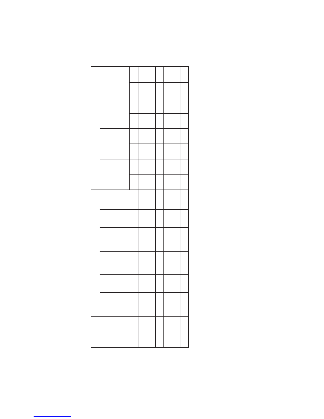
TABLE 1
2
2
1
3
2
2
eriWdnuorG
eziS
rewoPdleiF
eziSeriW
rekaerB.tkC
lanretxE
roesuF
mumixaM
yticapmA
muminiM
tiucriC
AtkCBtkCAtkCBtkCAtkCBtkCAtkCBtkC
dnuorG
eziS
eriW
rewoP
dleiF
eziS
eriW
lanretxE
rekaerB
roesuF
mumixaM
TIUCRICELGNIS TIUCRICLAUD
1
tiucriC
ELECTRICAL SPECIFICATIONS
yticapmA
muminiM
tiucriC
3
rewoP
.stkC
.oN
dleiF
esahP&
detaR
stloV
Z0A-162HS1-802/03212253801A/NA/NA/NA/NA/NA/NA/NA/N
ledoM
Z0B-162HS3-802/032171520101A/NA/NA/NA/NA/NA/NA/NA/N
01514141A/NA/NA/NA/NA/NA/NA/NA/N
Z0C-162HS3-0641
Z0A-113HS1-802/032162040101A/NA/NA/NA/NA/NA/NA/NA/N
11514141A/NA/NA/NA/NA/NA/NA/NA/N
Z0C-113HS3-0641
Z0B-113HS3-802/032102520101A/NA/NA/NA/NA/NA/NA/NA/N
1 Maximum size of the time delay fuse or HACR type circuit breaker for protection of field wiring conductors.
2 Based on 75° C copper wire. All wiring must conform to the National Electrical Code and all local codes.
3 These “Minimum Circuit Ampacity” values are to be used for sizing the field power conductors. Refer to the National Electric Code (latest
attention to Note 8 of Table 310 regarding Ampacity Adjustment Factors when more than three conductors are in a raceway.
revision), article 310 for power conductor sizing.
CAUTION: When more than one field power conductor circuit is run through one conduit, the conductors must be derated. Pay special
Manual 2100-409C
Page 6 of 25
Page 7
SHIPPING DAMAGE
Upon receipt of equipment, the carton should be
checked for external signs of shipping damage. If
damage is found, the receiving party must contact the
last carrier immediately, preferably in writing,
requesting inspection by the carrier’s agent.
GENERAL
The equipment covered in this manual is to be installed
by trained, experienced service and installation
technicians.
The refrigerant system is completely assembled and
charged. All internal wiring is complete.
The unit is designed for use with or without duct work.
Flanges are provided for attaching the supply and return
ducts.
These instructions explain the recommended method to
install the air cooled self-contained unit and the
electrical wiring connections to the unit.
These instructions and any instructions packaged with
any separate equipment required to make up the entire
heat pump system should be carefully read before
beginning the installation. Note particularly “Starting
Procedure” and any tags and/or labels attached to the
equipment.
While these instructions are intended as a general
recommended guide, they do not supersede any national
and/or local codes in any way. Authorities having
jurisdiction should be consulted before the installation is
made. See Page 3 for information on codes and
standards.
Size of unit for a proposed installation should be based
on heat loss calculation made according to methods of
Air Conditioning Contractors of America (ACCA). The
air duct should be installed in accordance with the
Standards of the National Fire Protection Association
for the Installation of Air Conditioning and Ventilating
Systems of Other Than Residence Type, NFPA No.
90A, and Residence Type Warm Air Heating and Air
Conditioning Systems, NFPA No. 90B. Where local
regulations are at a variance with instructions, installer
should adhere to local codes.
DUCT WORK
Any heat pump is more critical of proper operating
charge and an adequate duct system than a straight air
conditioning unit. All duct work, supply and return,
must be properly sized for the design airflow
requirement of the equipment. Air Conditioning
Contractors of America (ACCA) is an excellent guide to
proper sizing. All duct work or portions thereof not in
the conditioned space should be properly insulated in
order to both conserve energy and prevent condensation
or moisture damage.
Refer to Table 7 for maximum static pressure available
for duct design.
Design the duct work according to methods given by
the Air Conditioning Contractors of America (ACCA).
When duct runs through unheated spaces, it should be
insulated with a minimum of one inch of insulation.
Use insulation with a vapor barrier on the outside of the
insulation. Flexible joints should be used to connect the
duct work to the equipment in order to keep the noise
transmission to a minimum.
A 1/4 inch clearance to combustible material for the
first three feet (3') of duct attached to the outlet air
frame is required. See Wall Mounting Instructions and
Figures 3, 5 and 6 for further details.
Ducts through the walls must be insulated and all joints
taped or sealed to prevent air or moisture entering the
wall cavity.
CAUTION
Some installations may not require any return
air duct. A metallic return air grille is required
with installations not requiring a return air
duct. The spacing between louvers on the
grille shall not be larger than 5/8 inches.
Any grille that meets the 5/8 inch louver criteria, may be
used. It is recommended that Bard Return Air Grille Kit
RG-2 through RG-5 or RFG-2 through RFG-5 be
installed when no return duct is used. Contact
distributor or factory for ordering information. If using
a return air filter grille, filters must be of sufficient size
to allow a maximum velocity of 400 fpm.
NOTE: If no return air duct is used, applicable
installation codes may limit this cabinet to
installation only in a single story structure.
FILTERS
A 1-inch throwaway filter is supplied with each unit.
The filter slides into position making it easy to service.
This filter can be serviced from the outside by removing
the service door. A 1-inch washable filter and 2-inch
pleated filter are also available as optional accessories.
The internal filter brackets are adjustable to
accommodate the 2-inch filter by bending down the tabs
to allow spacing for the 2-inch filters.
Manual 2100-409C
Page 7 of 25
Page 8
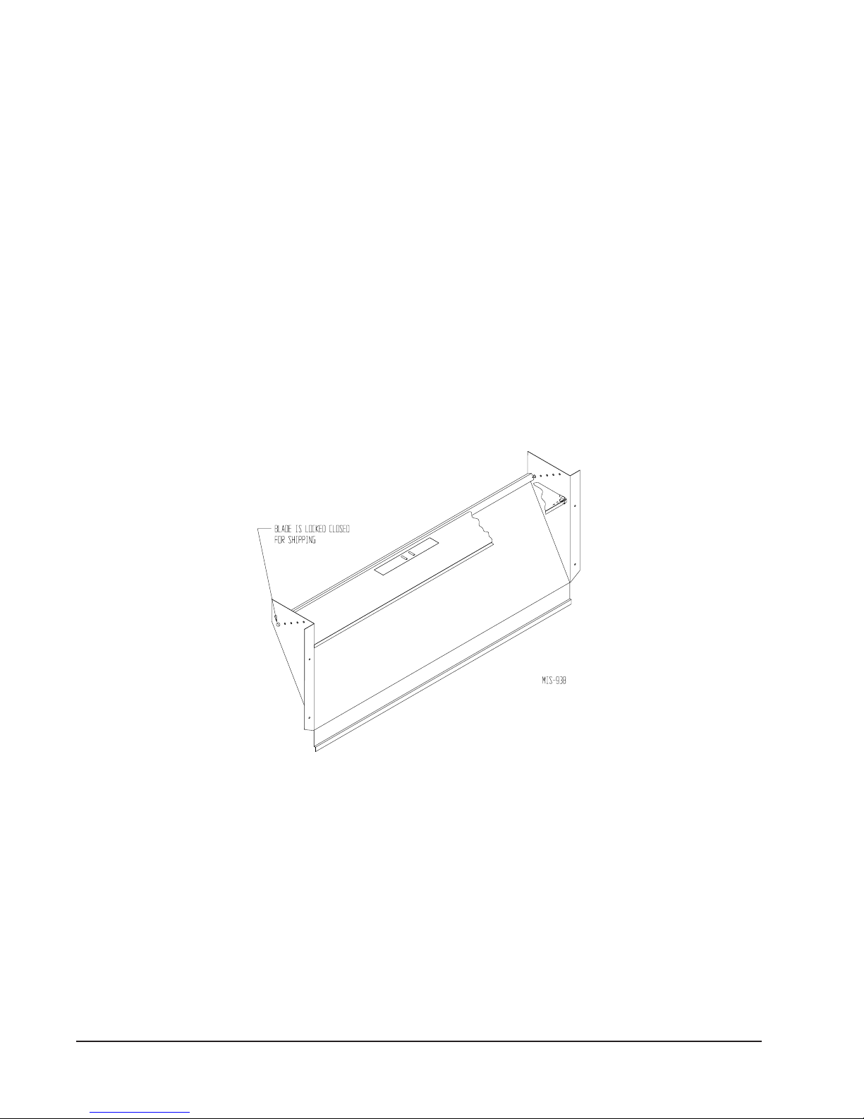
FRESH AIR INTAKE
All units are built with fresh air inlet slots punched in
the service panel.
The blank-off plate is available upon request from the
factory and is installed in place of the fresh air damper
shipped with each unit.
If the unit is equipped with the fresh air damper
assembly, the assembly is shipped already attached to
the unit. The damper blade is locked in the closed
position. To allow the damper to operate, the maximum
and minium blade position stops must be installed. See
Figure 2.
All capacity, efficiency and cost of operation
information as required for Department of Energy
“Energyguide” Fact Sheets is based upon the fresh air
blank-off plate in place and is recommended for
maximum energy efficiency.
BLOWER DAMPER ASSEMBLY
CONDENSATE DRAIN
A plastic drain hose extends from the drain pan at the
top of the unit down to the unit base. There are openings
in the unit base for the drain hose to pass through. In the
event the drain hose is connected to a drain system of
some type, it must be an open or vented type system to
assure proper drainage.
FIGURE 2
Manual 2100-409C
Page 8 of 25
Page 9

INSTALLATION INSTRUCTIONS
WALL MOUNTING INFORMATION
1. Two holes, for the supply and return air openings,
must be cut through the wall as shown in Figure 3.
2. On wood-frame walls, the wall construction must
be strong and rigid enough to carry the weight of
the unit without transmitting any unit vibration.
See Figures 4 and 5.
3. Concrete block walls must be thoroughly inspected
to insure that they are capable of carrying the
weight of the installing unit. See Figure 4.
MOUNTING THE UNIT
1. These units are secured by wall mounting brackets,
which secure the unit to the outside wall surface at
both sides. A bottom mounting bracket is provided
for ease of installation, but it is not required.
2. The unit itself is suitable for “0” inch clearance,
but the supply air duct flange and the first 3 feet of
supply air duct require a minimum of 1/4 inch
clearance to combustible material. If a
combustible wall, use a minimum of 28½" x 10½"
dimensions for sizing. However, it is generally
recommended that a 1-inch clearance is used for
ease of installation and maintaining the required
clearance to combustible material. The supply air
opening would then be 30" x 12". See Figures 3
and 4 for details.
3. Locate and mark lag bolt locations and bottom
mounting bracket location. See Figure 4.
4. Mount bottom mounting bracket. If used.
5. Hook top rain flashing under back bend of top.
Top rain flashing is shipped attached to the back of
the unit on the right side.
6. Position unit in opening and secure with 5/16 lag
bolts; use 3/4 inch diameter flat washers on the lag
bolts.
7. Secure rain flashing to wall and caulk across entire
length of top. See Figure 3.
8. For additional mounting rigidity, the return air and
supply air frames or collars can be drilled and
screwed or welded to the structural wall itself
(depending upon wall construction). Be sure to
observe required clearance if combustible wall.
9. On side-by-side installations, maintain a minimum
of 20 inches clearance on right side to allow access
to heat strips and control panel, and to allow proper
airflow to the outdoor coil. Additional clearance
may be required to meet local or national codes.
TYPICAL INSTALLATIONS
See Figure 7 for common ways to install the wall-mount
unit.
WARNING
Failure to provide the 1/4 inch clearance
between the supply duct and a combustible
surface for the first three feet of duct can
result in fire causing damage, bodily injury or
death.
Manual 2100-409C
Page 9 of 25
Page 10

FIGURE 3
MOUNTING INSTRUCTIONS
Manual 2100-409C
Page 10 of 25
Page 11

FIGURE 4
ELECTRIC HEAT CLEARANCE
WARNING
A minimum of 1/4" clearance must be maintained between the supply air duct
and combustible materials. This is required for the first three (3) feet of
ducting.
It is important to insure that the 1/4" minimum spacing is maintained at all
points.
Failure to do this could result in overheating the combustible material which
may result in a fire causing damage, injury, or death.
Manual 2100-409C
Page 11 of 25
Page 12

FIGURE 5
WALL MOUNTING INSTRUCTIONS
SEE FIGURE 3 – MOUNTING INSTRUCTIONS
FIGURE 6
WALL MOUNTING INSTRUCTIONS
SEE UNIT DIMENSIONS, FIGURE
1, FOR ACTUAL DIMENSIONS
Manual 2100-409C
Page 12 of 25
Page 13

FIGURE 7
COMMON WALL MOUNTING INSTALLATIONS
Manual 2100-409C
Page 13 of 25
Page 14

WIRING – MAIN POWER
Refer to the unit rating plate for wire sizing information
and maximum fuse or “HACR” type circuit breaker
size. Each outdoor unit is marked with a “Minimum
Circuit Ampacity”. This means that the field wiring
used must be sized to carry that amount of current.
Depending on the installed KW of electric heat, there
may be two field power circuits required. If this is the
case, the unit serial plate will so indicate. All models
are suitable only for connection with copper wire. Each
unit and/or wiring diagram will be marked “Use Copper
Conductors Only”. These instructions must be adhered
to. Refer to the National Electrical Code (NEC) for
complete current carrying capacity data on the various
insulation grades of wiring material. All wiring must
conform to NEC and all local codes.
The electrical data lists fuse and wire sizes (75° C
copper) for all models including the most commonly
used heater sizes. Also shown are the number of field
power circuits required for the various models with
heaters.
The unit rating plate lists a “Maximum Time Delay
Relay Fuse” or “HACR” type circuit breaker that is to
be used with the equipment. The correct size must be
used for proper circuit protection and also to assure that
there will be no nuisance tripping due to the momentary
high starting current of the compressor motor.
The disconnect access door on this unit may be locked
to prevent unauthorized access to the disconnect. To
convert for the locking capability, bend the tab located
in the bottom left hand corner of the disconnect opening
under the disconnect access panel straight out. This tab
will now line up with the slot in the door. When shut, a
padlock may be placed through the hole in the tab
preventing entry.
WIRING – LOW VOLTAGE WIRING
230/208V, 1 phase and 3 phase equipment dual primary
voltage transformers. All equipment leaves the factory
wired on 240V tap. For 208V operation, reconnect from
240V to 208V tap. The acceptable operating voltage
range for the 240 and 208V taps are:
TAP RANGE
240 253 – 216
208 220 – 187
NOTE: The voltage should be measured at the field
power connection point in the unit and while the
unit is operating at full load (maximum amperage
operating condition).
Nine (9) wires should be run from thermostat subbase to
the 24V terminal board in the unit. A nine conductor,
18 gauge copper color-coded thermostat cable is
recommended. The connection points are shown in
Figure 8.
FIGURE 8
UNIT 24V TERMINAL BOARD
IMPORTANT
Only the thermostats shown in this Manual
have been tested with this equipment for
proper operation. Proper unit operation with
thermostats
be assured.
You assume responsibility for proper operation
of the unit when using thermostats other than
those listed above.
AVALFeguaGeriW
553.2
not listed in this Manual, cannot
TABLE 2
THERMOSTAT WIRE SIZE
remrofsnarT
eguag02
eguag81
eguag61
egaug41
egaug21
mumixaM
ecnatsiD
teeFnI
54
06
001
061
052
Manual 2100-409C
Page 14 of 25
Page 15

OPTIONAL OUTDOOR THERMOSTAT
APPLICATIONS
Since most equipment at the time of manufacture is not
designated for any specific destination of the country
and are installed in areas not approaching the lower
outdoor temperature range, outdoor thermostats are not
factory installed as standard equipment, but are offered
as an option. There are also different applications for
applying outdoor thermostats. The set point of either
type of outdoor thermostat application is variable with
geographic region and sizing of the heating equipment to
the individual structure. Utilization of the heating
Application Data, and the heat loss calculation of the
building are useful in determining the correct set points.
NOTE: The additional LAB (low ambient bypass) relay
is required to prevent heater operation during low
temperature cooling operation.
COMPRESSOR CUTOFF THERMOSTAT WIRING
4 – 10KW 1 PH — 6 & 9KW 3 PH
OPTIONAL COMPRESSOR CUTOFF
THERMOSTAT (SEE FIGURES 9 AND 10)
Heat pump compressor operation at outdoor
temperatures below 0°F are neither desirable nor
advantageous in term of efficiency. An outdoor
thermostat can be applied to take the mechanical heating
(compressor) off line, and send the (compressor) signal
to energize electric heat in its place (to make electric
heat first stage heating). This can also be applied to
bank the quantity of available electric heat. For
example: A heat pump operates with 10KW second
stage heat – once the outdoor thermostat has switched
then operates 15KW without the compressor as first
stage heat.
FIGURE 9
FIGURE 10
COMPRESSOR CUTOFF THERMOSTAT WIRING
15 – 20KW 1 PH & 3 PH
Manual 2100-409C
Page 15 of 25
Page 16

ELECTRIC HEAT HOLD-OFF
(SEE FIGURES 11 AND 12)
In other applications, it is desirable to disable the
operation of the electric heat until outdoor temperatures
have reached a certain design point. This won't allow
the electric heat to come on as second stage heating
unless the outdoor temperature is below the set point of
the outdoor thermostat. This is done to maximize
ELECTRIC HEAT HOLD-OFF WIRING
4 – 10KW 1 PH — 6 & 9KW 3 PH
efficiency by utilizing the heat pump to bring the
conditioned space temperature up, rather than cycling on
the electric heat due a second stage call for heat from the
thermostat on start-up coming off a night set-back
condition or someone increasing the thermostat set
point. (NOTE: Some programmable thermostats do
have a built-in time delay for pulling in second stage
heat when coming off set-back conditions.)
FIGURE 11
Manual 2100-409C
Page 16 of 25
FIGURE 12
ELECTRIC HEAT HOLD-OFF WIRING
15 – 20KW 1 PH & 3 PH
Page 17

THERMOSTAT INDICATORS
8403-049 (1F93-380) Thermostat:
In heating and cooling, the LED will illuminate green
for first stage and yellow for second stage. The same
LED will illuminate red for Emergency heating mode
and will flash red if there is a malfunction in the system.
The Malfunction indicator is accomplished by a relay
output from the heat pump control board. A condition
such as loss of charge or high head pressure will cause
the flashing red light to activate. This is a signal to the
operator of the equipment to place system in the
emergency position.
8403-058 (TH5220D1151) Thermostat:
Thermostat will display on the screen “Em Heat” when
the thermostat is set on emergency heat.
LOW VOLTAGE CONNECTIONS
These units use a grounded 24 volt AC low voltage
circuit.
The “R” terminal is the hot terminal and the “C”
terminal is grounded.
“G” terminal is the fan input.
“Y” terminal is the compressor input.
“B” terminal is the reversing valve input. The reversing
valve must be energized for heating mode.
“R” terminal is 24 VAC hot.
“C” terminal is 24 VAC grounded.
“L” terminal is compressor lockout
output
. This
terminal is activated on a high or low pressure trip by
the electronic heat pump control. This is a 24 VAC
output.
“W2” terminal is second stage heat (if equipped).
“O1” terminal is the ventilation input. This terminal
energizes any factory installed ventilation option.
“E” terminal is the emergency heat input. This terminal
energizes the emergency heat relay.
NOTE: For total and proper control using DDC, a total of
6 controlled outputs are required (5 if no
ventilation system is installed). For proper system
operation under Emergency Heat conditions
where the compressor needs to be deactivated, the
B-W2-E outputs need to be energized. Removing
the Y (compressor) signal alone turns the
compressor off, but does not activate the
additional circuitry embedded in the heat pump
for proper and complete operation.
TABLE 3
WALL THERMOSTAT
tatsomrehTserutaeFtnanimoderP
940-3048
)083-39F1(
850-3048
)1511D0225HT(
LOW VOLTAGE CONNECTIONS
taehegats3;loocegats2
cinortcelEelbammargorP
revoegnahclaunaMrootuA
taehegats2;loocegats2
elbammargorP-noNcinortcelE
revoegnahclaunaMrootuA
Fan Only Energize G
Cooling Mode Energize Y, G
Heat Pump Heating Energize Y, G, B
2nd Stg Heating Energize G, W2, Y, B
w/Heat Pump (if employed)
Ventilation Energize G, O1
Emergency Heat Energize B, W2, E, G
FOR
DDC CONTROL
Manual 2100-409C
Page 17 of 25
Page 18

START UP
IMPORTANT INSTALLER NOTE
For improved start up performance wash the indoor coil
with a dish washing detergent.
HIGH PRESSURE SWITCH
All models are supplied with a remote reset high
pressure switch. If tripped, this pressure switch may be
reset by turning the thermostat off then back on again.
THREE PHASE SCROLL COMPRESSOR
START UP INFORMATION
Scroll compressors, like several other types of
compressors, will only compress in one rotational
direction. Direction of rotation is not an issue with
single phase compressors since they will always start
and run in the proper direction.
However, three phase compressors will rotate in either
direction depending upon phasing of the power. Since
there is a 50-50 chance of connecting power in such a
way as to cause rotation in the reverse direction,
verification of proper rotation must be made. All three
phase units incorporate a phase monitor to ensure proper
field wiring. See the “Phase Monitor” section later in
this manual.
Verification of proper rotation must be made any time a
compressor is changed or rewired. If improper rotation
is corrected at this time there will be no negative impact
on the durability of the compressor. However, reverse
operation for over one hour may have a negative impact
on the bearing due to oil pump out.
NOTE: If compressor is allowed to run in reverse
rotation for several minutes, the compressor’s
internal protector will trip.
All three phase ZR3 compressors are wired identically
internally. As a result, once the correct phasing is
determined for a specific system or installation,
connecting properly phased power leads to the same
Fusite terminal should maintain proper rotation
direction.
Verification of proper rotation direction is made by
observing that suction pressure drops and discharge
pressure rises when the compressor is energized.
Reverse rotation also results in an elevated sound level
over that with correct rotations, as well as, substantially
reduced current draw compared to tabulate values.
The direction of rotation of the compressor may be
changed by reversing any two line connections to the
unit.
PHASE MONITOR
All units with three phase compressors are equipped
with a 3 phase line monitor to prevent compressor
damage due to phase reversal.
The phase monitor in this unit is equipped with two
LEDs. If the Y signal is present at the phase monitor
and phases are correct, the green LED will light. If
phases are reversed, the red fault LED will be lit and
compressor operation is inhibited.
If a fault condition occurs, reverse two of the supply
leads to the unit. Do not reverse any of the unit factory
wires as damage may occur.
SERVICE HINTS
1. Caution homeowner to maintain clean air filters at
all times. Also, not to needlessly close off supply
and return air registers. This reduces airflow
through the system, which shortens equipment
service life as well as increasing operating costs.
2. Switching to heating cycle at 75° F or higher
outside temperature may cause a nuisance trip of
the remote reset high pressure switch. Turn
thermostat off then on to reset the high pressure
switch.
3. The heat pump wall thermostats perform multiple
functions. Be sure that all function switches are
correctly set for the desired operating mode before
trying to diagnose any reported service problems.
4. Check all power fuses or circuit breakers to be sure
they are the correct rating.
5. Periodic cleaning of the outdoor coil to permit full
and unrestricted airflow circulation is essential.
SEQUENCE OF OPERATION
COOLING – Circuit R-Y makes at thermostat pulling
in compressor contactor, starting the compressor and
outdoor motor. The G (indoor motor) circuit is
automatically completed on any call for cooling
operation or can be energized by manual fan switch on
subbase for constant air circulation.
HEATING – A 24V solenoid coil on reversing valve
controls heating cycle operation. Two thermostat
options, one allowing “Auto” changeover from cycle to
cycle and the other constantly energizing solenoid coil
during heating season and thus eliminating pressure
equalization noise except during defrost, are to be used.
On “Auto” option a circuit is completed from R-W1 and
R-Y on each heating “on” cycle, energizing reversing
valve solenoid and pulling in compressor contactor
starting compressor and outdoor motor. R-G also make
starting indoor blower motor.
Manual 2100-409C
Page 18 of 25
Page 19

Heat pump heating cycle now in operation. The second
option has no “Auto” changeover position, but instead
energizes the reversing valve solenoid constantly
whenever the system switch on subbase is placed in
“Heat” position, the “B” terminal being constantly
energized from R. A thermostat demand for heat
completes R-Y circuit, pulling in compressor contactor
starting compressor and outdoor motor. R-G also make
starting indoor blower motor.
PRESSURE SERVICE PORTS
High and low pressure service ports are installed on all
units so that the system operating pressures can be
observed. Pressure tables can be found later in the
manual covering all models on both cooling and heating
cycles. It is imperative to match the correct pressure
table to the unit by model number.
DEFROST CYCLE
The defrost cycle is controlled by temperature and time
on the solid state heat pump control. See Figure 13.
When the outdoor temperature is in the lower 40° F
temperature range or colder, the outdoor coil
temperature is 32° F or below. This coil temperature is
sensed by the coil temperature sensor mounted near the
bottom of the outdoor coil. Once coil temperature
reaches 30° F or below, the coil temperature sensor
sends a signal to the control logic of the heat pump
control and the defrost timer will start.
After 60 minutes at 30° F or below, the heat pump
control will place the system in the defrost mode.
During the defrost mode, the refrigerant cycle switches
back to the cooling cycle, the outdoor motor stops,
electric heaters are energized, and hot gas passing
through the outdoor coil melts any accumulated frost.
When the temperature rises to approximately 57° F, the
coil temperature sensor will send a signal to the heat
pump control which will return the system to heating
operations automatically.
If some abnormal or temporary condition such as a high
wind causes the heat pump to have a prolonged defrost
cycle, the heat pump control will restore the system to
heating operation automatically after 10 minutes.
The heat pump defrost control board has an option of
30, 60 or 90-minute setting. All models are shipped
from the factory on the 60-minute pin. If special
circumstances require a change to another time, remove
the wire from the 60-minute terminal and reconnect to
the desired terminal. The manufacturer's
recommendation is for 60-minute defrost cycles. Refer
to Figure 13.
Use a small screwdriver or other metallic object, or
another 1/4 inch QC, to short between the SPEEDUP
terminals to accelerate the HPC timer and initiate
defrost.
Be careful not to touch any other terminals with the
instrument used to short the SPEEDUP terminals. It
may take up to 10 seconds with the SPEEDUP
terminals shorted for the speedup to be completed and
the defrost cycle to start.
As soon as the defrost cycle kicks in remove the
shorting instrument from the SPEEDUP terminals.
Otherwise the timing will remain accelerated and run
through the 1-minute minimum defrost length sequence
in a matter of seconds and will automatically terminate
the defrost sequence.
There is an initiate defrost jumper (sen jump) on the
control that can be used at any outdoor ambient during
the heating cycle to simulate a 0° coil temperature. This
can be used to check defrost operation of the unit
without waiting for the outdoor ambient to fall into the
defrost region.
By placing a jumper across the SEN JMP terminals (a
1/4 inch QC terminal works best) the defrost sensor
mounted on the outdoor coil is shunted out and will
activate the timing circuit. This permits the defrost
cycle to be checked out in warmer weather conditions
without the outdoor temperature having to fall into the
defrost region.
In order to terminate the defrost test the SEN JMP
jumper must be removed. If left in place too long the
compressor could stop due to the high pressure control
opening because of high pressure condition created by
operating in the cooling mode with outdoor fan off.
Pressure will rise fairly fast as there is likely no actual
frost on the outdoor coil in this artificial test condition.
There is also a 5-minute compressor time delay function
built into the HPC. This is to protect the compressor from
short cycling conditions. In some instances it is helpful to
the service technician to override or speed up this timing
period, and shorting out the SPEEDUP terminals for a few
seconds can do this.
Manual 2100-409C
Page 19 of 25
Page 20

FIGURE 13
DEFROST CONTROL BOARD
Manual 2100-409C
Page 20 of 25
Page 21

TROUBLESHOOTING
SOLID STATE HEAT PUMP CONTROL
TROUBLESHOOTING PROCEDURE
1. Turn on AC power supply to indoor and outdoor
units.
2. Turn thermostat blower switch to fan on. The
indoor blower should start. (If it doesn’t,
troubleshoot indoor unit and correct problem.)
TROUBLESHOOTING
motpmySsesuaCelbissoPkcehCottahWriapeRrokcehDotwoH
rosserpmoC
tonseodrotcatnoc
rognitaeh(ezigrene
)gnilooc
noitcetorp
evitcefed
tcerroc
rotomroodtuonaF
nurtonseod
gnitaehrognilooc(
gnirudtpecxe
)tsorfed
evlavgnisreveR
ezigrenetonseod
)ylnognitaeh(
otniogtonlliwtinU
tsorfed
)ylnognitaeh(
emoctonlliwtinU
tsorfedfotuo
)ylnognitaeh(
evitcefed
evitcefed
evitcefed
evitcefed
evitcefed
gniriwtiucriclortnoCtinutaoitcennocRrofkcehC
tuokcolrosserpmoC.1
.2
elcyctrohsrosserpmoC
lortnocpmuptaeH
evitcefedrotcatnoCliocdetrohsroneporofkcehC
tongnisahprewoP
evitcefedrotoMdetrohsroneporofkcehC
roticapacrotoM
lortnocpmuptaeH
dionelosevlavgnisreveR
evitcefedlioc
lortnocpmuptaeH
rorosneserutarepmeT
lortnocpmuptaeh
rorosneserutarepmeT
lortnocpmuptaeh
TABLE 4
.gnidniw
.gnidniwrotom
.C-Bdna
.etunimeno
3. Turn thermostat blower switch to auto position.
Indoor blower should stop.
4. Set system switch to heat or cool. Adjust
thermostat to call for heat or cool. The indoor
blower, compressor, and outdoor fan should start.
NOTE: If there was no power to 24 volt transformer, the
compressor and outdoor fan motor will not start
for 5 minutes. This is because of the compressor
short cycle protection.
C-Rneewtebtlov42dna
neewtebV42rofkcehC
hgihssorcakcehC
hctiwserusserp
.1
.lortnocpmuptaehnoC-1L
.2
C-CCneewtebV42rofkcehC
.lortnocpmuptaehnoC-Ydna
.lortnocpmup
erusserphgihteserotniaganodnaffo
.hctiws
.hctiwserusserphgihecalper,teser
evomeR.C-CCneewtebraeppadluohs
.sdnoces01retfarepmujpudeeps
elbissoprehtollakcehC
560-0012launaM.sesuac
.lortnocpmuptaehecalpeR
.rotcatnocecalpeR
esahpnoDELderrofkcehC
.)ylnostinuesahp3(rotinom
.tinuehtotsdaelrewopowthctiwS
.rotomecalpeR
kcehC.gntarroticapackcehC
.roticapacdetrohsroneporof
noyalernafssorcakcehC
.)CN-moC(lortnocpmuptaeh
.liocdetrohsroneporofkcehC
C-VRneewtebV42rofkcehC
.1
.2
erutarepmettcennocsiD
sihT.slanimretpmujnes
ogottinuehtesuracdluohs
pudeepsssorcarepmuJ
.etunimenonihtiw
.1
repmujdnadraobmorfrosnes
dnaslanimretpudeepsssorca
.2
nihtiwelcyctsorfedahguorht
.1
esuacdluohssihT.slanimret
tsorfedfotuoemocottinueht
.2
.roticapacecalpeR
.lortnocpmuptaehecalpeR
.lioCdionelosecalpeR
.gniriwtiucriclortnockcehC
.lortnocpmuptaehecalpeR
.rosneserutarepmet
.lortnocpmuptaehecalper
.rosneserutarepmet
tsorfedfotuoemoctonseodtinufI
.lortnocpmuptaehecalper,elcyc
taehrewopottinuroodtuootnoitcennocRnuR
tatsomrehtnrut,C-1LneewtebegatlovonfI
tonlliwdnaneposihctiwserusserphgihfI
deepsrepmuj,C-CCneewtebegatlovtonfI
rewopsdnoces01nihtiwdna,lanimretpu
ecalper,elcyctsorfedhguorhtseogtinufI
,elcyctsorfedhguorhtogtonseodtinufI
ecalperelcyctsorfedfotuosemoctinufI
Manual 2100-409C
Page 21 of 25
Page 22

CHECKING TEMPERATURE SENSOR
OUTSIDE UNIT CIRCUIT
1. Disconnect temperature sensor from board and
from outdoor coil.
2. Use an ohmmeter and measure the resistance of the
sensor. Also use ohmmeter to check for short or
open.
TEMPERATURE F VS RESISTANCE R OF TEMPERATURE
F R F R F R
-25.0
-24.0
-23.0
-22.0
-21.0
-20.0
-19.0
-18.0
-17.0
-16.0
-15.0
-14.0
-13.0
-12.0
-11.0
-10.0
-9.0
-8.0
-7.0
-6.0
-5.0
-4.0
-3.0
-2.0
-1.0
0.0
1.0
2.0
3.0
4.0
5.0
6.0
7.0
8.0
9.0
10.0
11.0
12.0
13.0
14.0
15.0
16.0
17.0
18.0
19.0
20.0
21.0
22.0
23.0
24.0
196871
190099
183585
177318
171289
165487
159904
154529
149355
144374
139576
134956
130506
126219
122089
118108
114272
110575
107010
103574
100260
97064
93981
91008
88139
85371
82699
80121
77632
75230
72910
70670
68507
66418
64399
62449
60565
58745
56985
55284
53640
52051
50514
49028
47590
46200
44855
43554
42295
41077
25.0
26.0
27.0
28.0
29.0
30.0
31.0
32.0
33.0
34.0
35.0
36.0
37.0
38.0
39.0
40.0
41.0
42.0
43.0
44.0
45.0
46.0
47.0
48.0
49.0
50.0
51.0
52.0
53.0
54.0
55.0
56.0
57.0
58.0
59.0
60.0
61.0
62.0
63.0
64.0
65.0
66.0
67.0
68.0
69.0
70.0
71.0
72.0
73.0
74.0
3. Check resistance reading to chart of resistance use
sensor ambient temperature. (Tolerance of part is
± 10%)
4. If sensor resistance reads very low, then sensor is
shorted and will not allow proper operation of the
heat pump control.
5. If sensor is out of tolerance, shorted, open, or reads
very low ohms then it should be replaced.
39898
38757
37652
36583
35548
34545
33574
32634
31723
30840
29986
29157
28355
27577
26823
26092
25383
24696
24030
23384
22758
22150
21561
20989
20435
19896
19374
18867
18375
17898
17434
16984
16547
16122
15710
15310
14921
14544
14177
13820
13474
13137
12810
12492
12183
11883
11591
11307
11031
10762
75.0
76.0
77.0
78.0
79.0
80.0
81.0
82.0
83.0
84.0
85.0
86.0
87.0
88.0
89.0
90.0
91.0
92.0
93.0
94.0
95.0
96.0
97.0
98.0
99.0
100.0
101.0
102.
103.0
104.0
105.0
106.0
107.0
108.0
109.0
110.0
111.0
112.0
113.0
114.0
115.0
116.0
117.0
118.0
119.0
120.0
121.0
122.0
123.0
124.0
10501
10247
10000
9760
9526
9299
9077
8862
8653
8449
8250
8057
7869
7686
7507
7334
7165
7000
6840
6683
6531
6383
6239
6098
5961
5827
5697
0
5570
5446
5326
5208
5094
4982
4873
4767
4663
4562
4464
4367
4274
4182
4093
4006
3921
3838
3757
3678
3601
3526
3452
Manual 2100-409C
Page 22 of 25
Page 23

FAN BLADE SETTING DIMENSIONS
ledoM
detaR
*MFC
detaR
*PSE
dednemmoceR
egnaRwolfriA
162HS
113HS
008
008
01.
01.
009-006
009-006
REFRIGERANT CHARGE
Shown in Figure 14 are the correct fan blade setting
dimensions for proper air delivery across the outdoor
coil.
Any service work requiring removal or adjustment in
the fan and/or motor area will require that the
dimensions below be checked and blade adjusted in or
out on the motor shaft accordingly.
FIGURE 14
FAN BLADE SETTING
AIRFLOW
MIS-1724
TABLE 5
FAN BLADE SETTING
ledoMAnoisnemiD
162HS
113HS
52.1
REMOVAL OF FAN SHROUD
"A"
The correct system R-22 charge is shown on the unit
rating plate. Optimum unit performance will occur with
a refrigerant charge resulting in a suction line
temperature (6” from compressor) as shown in Table 6.
TABLE 6
REFRIGERANT CHARGE
detaR
ledoM
162HS
113HS
wolfriA
008
008
DOF°59
erutarepmeT
96-76
86-66
DOF°28
66-46
66-46
The suction line temperatures in Table 6 are based upon
80° F dry bulb / 67° F wet bulb (50% R.H.) temperature
and rated airflow across the evaporator during cooling
cycle.
TABLE 7
INDOOR BLOWER PERFORMANCE
CFM @ 230V
113HS,162HS
deepSwoLdeepShgiH
.P.S.E
HnI2O
0.
1.
2.
3.
yrD
lioC
teW
059
048
057
---
yrD
lioC
009
008
056
lioC
0501
009
057
---
006
teW
lioC
0001
058
007
055
erutarepmeT
1. Disconnect all power to the unit.
2. Remove the screws holding both grilles, one on
each side of unit, and remove grilles.
3. Remove screws holding fan shroud to condenser
and bottom. Nine (9) screws.
4. Unwire condenser fan motor.
5. Slide complete motor, fan blade, and shroud
assembly out the left side of the unit.
6. Service motor/fan as needed.
7. Reverse steps to reinstall.
NOTE: The SH261 and SH311 are shipped with the
indoor blower on high speed for ducted applications.
Move to low speed for free blow applications.
TABLE 8
RECOMMENDED OPERATING RANGES
* Rated CFM and ESP on high speed tap.
Manual 2100-409C
Page 23 of 25
Page 24

TABLE 9
PRESSURE TABLE
Air Temperature Entering Outdoor Coil °FCOOLING
riAnruteR
ledoM
162HS
113HS
erutarepmeTerusserP5708580959001501011511
BD.ged57
BW.ged26
BD.ged08
BW.ged76
BD.ged58
BW.ged27
BD.ged57
BW.ged26
BD.ged08
BW.ged76
BD.ged58
BW.ged27
ediSwoL
ediShgiH
ediSwoL
ediShgiH
ediSwoL
ediShgiH
ediSwoL
ediShgiH
ediSwoL
ediShgiH
ediSwoL
ediShgiH
87
97
08
18
18
28
38
38
002
512
232
152
962
092
213
433
38
48
68
78
78
88
98
98
502
122
832
752
672
792
023
343
68
78
98
09
09
19
29
29
212
922
642
662
682
703
133
553
37
47
57
67
77
87
87
97
091
502
022
732
452
272
192
903
87
97
08
18
28
38
38
48
591
012
622
342
062
972
892
713
18
28
38
48
58
68
68
78
202
712
432
252
962
982
803
823
48
953
09
863
39
183
97
033
48
833
78
053
TABLE 10
PRESSURE TABLE
HEATING
riAnruteR
ledoM
162HS.ged07
113HS.ged07
Low side pressure ± 2 PSIG
High side pressure ± 5 PSIG
are based upon rated CFM (airflow) across the evaporator coil. If there is any doubt as to correct
Tables
operating charge being in the system, the charge should be removed, system evacuated and recharged to
serial plate instruction.
erutarepmeTerusserP05015102520353045405550656
ediSwoL
21
71
22
72
23
ediShgiH
251
951
561
271
871
ediSwoL
91
12
42
72
03
ediShgiH
481
581
781
091
591
Air Temperature Entering Outdoor Coil °F
73
24
84
38
85
36
581
291
891
502
212
912
43
83
34
84
45
06
102
802
612
622
732
942
96
47
08
622
332
042
76
47
28
362
872
492
Manual 2100-409C
Page 24 of 25
Page 25

TABLE 11
OPTIONAL ACCESSORIES
SH261-A
SH261-B
SH261-C
SH311-A
SH311-B
X
X
X
SH311-C
X
X
X
X
ledoMnoitpircseD
3-POBetalPffOknalB XXXXXX
3-DAFBrepmaDriAhserFcirtemoraB XXXXXX
3-DAFMrepmaDriAhserFdezirotoM XXXXXX
A3A-VREW
A3C-VREW
3-HMC
7-HMC
9-HMC
41-HMC)TDO(tatsomrehTroodtuO
51-CMC)KS(tiKtratSXX
CPL+CAL
rotalitneVyrevoceRygrenE
rotalitneVyrevoceRygrenE
)CPL(lortnoCerusserPwoL
)CAL(lortnoCtneibmAwoL
XX
X
X
X
X
X
X
XXXXXX
X
X
X
X
XX
X
X
X
Manual 2100-409C
Page 25 of 25
 Loading...