

Bard PH13242-A, PH13422-A, PH13422-B, PH13422-C, PH13482-A Installation Instructions Manual
...
INSTALLATION INSTRUCTIONS
SINGLE PACKAGE
HEAT PUMPS
MODELS
PH13242-A PH13302-A
PH13363-A PH13363-B
PH13422-A PH13422-B
PH13422-C PH13482-A
PH13482-B PH13482-C
PH13602-A PH13602-B
PH13602-C
Bard Manufacturing Company, Inc.
Bryan, Ohio 43506
Since 1914 . . . Moving ahead, just as planned.
Manual : 2100-468J
Supersedes: 2100-468
File: Volume II Tab 11
Date: 07-25-12
I
Manual 2100-468J
Page 1 of 29

CONTENTS
Getting Other Informations and Publications .........3
General Instructions
Important .................................................................4
Shipping Damage .....................................................4
General .................................................................4
Field-Installed Heater Packages (Optional) ..............4
Installation
Location ...............................................................10
Slab Mounting .........................................................10
Winter Installation ...................................................10
Typical Installations .........................................10 & 13
Condensate Drain Trap ...........................................13
Air Filters ...............................................................13
Thermostats ............................................................14
Wiring – Main Power ...............................................15
Wiring – 24V Low Voltage Control Circuit ...............15
Thermostat Indicator Lamps ...................................16
Emergency Heat Position .......................................16
Transformer Taps ....................................................16
Compressor Cutoff Thermostat and Outdoor ..........16
Figures
Figure 1A Unit Dimensional Drawing ........................8
Figure 1B Unit Dimensional Drawing ........................9
Figure 2 Slab Mounting at Ground Level .............. 11
Figure 3 Airow and Service Access
Clearances .............................................11
Figure 4 Elevated Mounting Platform ...................12
Figure 5 Condensate Drain Trap ..........................13
Figure 6 Low Voltage Wiring ................................15
Figure 7 Unit 24V Terminal Board (5–10 KW) ......16
Figure 8 Unit 24V Terminal Board (15–20 KW) ....17
Figure 9 Defrost Control Board ............................20
Figure 10 Fan Blade Setting ...................................24
Figure 11 Brazing Diagram ....................................27
Figure 12 Motor Connections .................................28
Figure 13 Wiring (Connections/Voltage) .................29
Start Up and Operation
General ...............................................................18
Topping Off System Charge ....................................18
Safety Practices ......................................................18
Start Up Notes ........................................................18
Three Phase Scroll Compressor Start Up
Information ..............................................................19
Sequence of Operation ...........................................19
Defrost Cycle ..................................................20 & 21
Troubleshooting
Solid State Heat Pump Control
Troubleshooting Procedure .....................................22
Troubleshooting Guide ............................................22
Checking Temperature Sensor Check Out .............23
Temperature vs. Resistance of
Temperature Sensor Chart ......................................23
Service
Service Hints ...........................................................24
Pressure Service Ports ...........................................24
R-410A Refrigerant Charge ....................................24
Fan Blade Settings .................................................24
Suction and Discharge Tube Brazing ......................27
Pressure Tables ..............................................24 & 25
Troubleshooting GE ECM Blower Motors ...28 & 29
Tables
Table 1 Rated CFM and ESP ................................4
Table 2 Electrical Data ..........................................5
Table 3 Optional Field Installed Heater
Packages .................................................6
Table 4 Opt. Field Installed Elec. Heater ..............7
Table 5 Required Filters ......................................13
Table 6 Heat Pump Thermostats ........................14
Table 7 Thermostat Wire Size .............................14
Table 8 Compressor Cutoff Thermostat
Wiring (5 - 10 KW) .................................17
Table 9 Compressor Cutoff Thermostat
Wiring (15 - 20 KW) ...............................17
Table 10 Troubleshooting......................................22
Table 11 Pressure Table - Cooling & Heating .......25
Table 12 Pressure Table - Cooling & Heating .......26
Table 13 Indoor Blower Performance ...................27
Manual 2100-468J
Page 2 of 29

Getting Other Information and Publications
These publications can help you install the air conditioner
or heat pump. You can usually nd these at your local
library or purchase them directly from the publisher. Be
sure to consult current edition of each standard.
National Electrical Code ............................ANSI/NFPA 70
Standard for the Installation ....................ANSI/NFPA 90A
of Air Conditioning and Ventilating Systems
Standard
Heating and Air Conditioning Systems
Load Calculation for
Residential Winter and Summer Air Conditioning
Duct Design for Residential ....................ACCA Manual D
Winter and Summer Air Conditioning and Equipment
Selection
for Warm Air ............................ANSI/NFPA 90B
..............................ACCA Manual J
FOr mOre InFOrmatIOn, cOntact
these PublIshers:
ACCA Air Conditioning Contractors of America
1712 New Hampshire Ave. N.W.
Washington, DC 20009
Telephone: (202) 483-9370
Fax: (202) 234-4721
ANSI American National Standards Institute
11 West Street, 13th Floor
New York, NY 10036
Telephone: (212) 642-4900
Fax: (212) 302-1286
ASHRAE American Society of Heating Refrigerating,
and Air Conditioning Engineers, Inc.
1791 Tullie Circle, N.E.
Atlanta, GA 30329-2305
Telephone: (404) 636-8400
Fax: (404) 321-5478
NFPA National Fire Protection Association
Batterymarch Park
P.O. Box 9101
Quincy, MA 02269-9901
Telephone: (800) 344-3555
Fax: (617) 984-7057
Manual 2100-468J
Page 3 of 29
General InstructIOns
ImPOrtant
The equipment covered in this manual is to be installed by
trained, experienced service and installation technicians.
Any heat pump is more critical of proper operating
charge and an adequate duct system than a straight air
conditioning unit. All duct work, supply and return ducts,
must be properly sized for the design airow requirement
of the equipment. ACCA is an excellent guide to proper
sizing. All duct work or portions thereof not in the
conditioned space should be properly insulated in order
to both conserve energy and prevent condensation or
moisture damage.
shIPPInG DamaGe
Upon receipt of equipment, the carton should be checked
for external signs of shipping damage. If damage is
found, the receiving party must contact the last carrier
immediately, preferably in writing, requesting inspection
by the carrier’s agent.
General
The refrigerant system is completely assembled and
charged. All internal wiring is complete.
The unit is designed for use with or without duct work.
Flanges are provided for attaching the supply and return
ducts.
These instructions and any instructions packaged with any
separate equipment required to make up the entire heat
pump system should be carefully read before beginning
the installation. Note particularly “Starting Procedure”
and any tags and/or labels attached to the equipment.
While these instructions are intended as a general
recommended guide, they do not supersede any national
and/or local codes in any way. Authorities having
jurisdiction should be consulted before the installation is
made.
FIelD InstalleD heater PacKaGes
(OPtIOnal)
These packaged heat pumps are manufactured without
supplementary electric heaters. Supplementary heaters are
available for simple, fast eld installation.
A separate power circuit is required for the supplementary
heaters.
IMPORTANT: Refer to Table 1 when designing duct
work for maximum available static pressure with heater
installed.
Refer to Tables 2 and 4 for proper application information
on all available heater combinations and what units they
can be used with. It also shows the applicable circuit
ampacities, fuse size, and wire size for each heater
combination.
These instructions explain the recommended method to
install the air cooled self-contained unit and the electrical
wiring connections to the unit.
rateD cFm anD external statIc Pressure (esP)
model
no.
PH1324 800 Note 0.10 0.50
PH1330 1000 Note 0.15 0.50
PH1336 1100 Note 0.15 0.50
PH1342 1450 Note 0.15 0.50
PH1348 1550 Note 0.20 0.50
PH1360 1750 Note 0.20 0.50
rated
cFm
NOTE: Motor will adjust to deliver rated airow.
table 1
recommended
Airow Range
rated
esP
max.
esP
Manual 2100-468J
Page 4 of 29

460-60-3
230/208-60-1 230/208-60-3
460-60-3
230/208-60-1 230/208-60-3
460-60-3
table 2
electrIcal Data
230/208-60-1 230/208-60-1 230/208-60-1 230/208-60-3 230/208-60-1 230/208-60-3
electric rating –
60 hz – circuit a
model Ph13242-a Ph13302-a Ph13363-a Ph13363-b Ph13422-a Ph13422-b Ph13422-c Ph13482-a Ph13482-b Ph13482-c Ph13602-a Ph13602-b Ph13602-c
Operating Voltage Range 197 - 253 197 - 253 197 - 253 187 - 253 197 - 253 187 - 253 414-506 197 - 253 187 - 253 414-506 197 - 253 187 - 253 414-506
Fan motor and condenser
Fan Motor – HP/RPM 1/6 / 825 1/6 / 825 1/6 / 825 1/6 / 825 1/4 / 825 1/4 / 825 1/4 / 825 1/4 / 825 1/4 / 825 1/4 / 825 1/4 / 825 1/4 / 825 1/4 / 825
Fan Motor Amps 1.1 1.1 1.1 1.1 1.5 1.5 1.5 1.5 1.5 1.5 1.5 1.5 1.5
Minimum Circuit Ampacity 20 22 27 18 33 25 12 36 29 14 39 26 17
BCSC 13 14 17.5 11 21 15 8 22 14 8 26 16 9
Field Wire Size * 12 10 10 12 10 10 14 8 10 12 8 10 10
Ground Wire Size 12 10 8 12 10 10 14 8 10 14 8 10 12
Delay Fuse – Max. ** 30 30 40 25 50 35 15 50 40 20 60 40 25
Total unit Amps – 230/208 11.2/12.2 14.8/16.3 19.4/21.9 13.9/15.4 21.9/22.9 17.1/17.9 10.4 24.7/26.6 18.0/19.2 10.7 25.3/28.9 17.7/19.9 11.9
compressor – circuit a
Compressor Type Scroll Scroll Scroll Scroll Scroll Scroll Scroll Scroll Scroll Scroll Scroll Scroll Scroll
Volts 230/208 230/208 230/208 230/208 230/208 230/208 460 230/208 230/208 460 230/208 230/208 460
Rated Load Amps 8/9 11/12.5 15/17.5 9.5/11 16.1/17.1 11.3/12.0 7.7 18.7/20.6 12.0/13.2 7.7 19.3/22.9 11.7/13.9 8.6
Lock Rotor Amps 58.3/58.3 73/73 79/79 88/88 115/115 115/115 50 117/117 83.1/83.1 50 134/134 110/110 52
Fan – Dia./CFM 24"/2800 24"/2600 24"2600 24"/2600 24"/3400 24"/3400 24"/3400 24"/3400 24"/3400 24"/3400 24"/3400 24"/3400 24"/3400
motor and evaporator
Blower Motor – HP/RPM 1/3 ECM 1/2 ECM 1/2 ECM 1/2 ECM 1/2 ECM 1/2 ECM 1/2 ECM 3/4 ECM 3/4 ECM 3/4 ECM 3/4 ECM 3/4 ECM 3/4 ECM
Blower Motor – Amps 2.1 2.7 3.3 3.3 3.9 3.9 3.9 4.5 4.5 4.5 5.0 5.0 5.0
CFM Cooling 800 1000 1000 1000 1450 1450 1450 1550 1550 1550 1750 1750 1750
Charge (R-410A oz.) 75 136 136 136 170 170 160 180 180 160 190 190 160
Shipping Weight (pounds) 360 410 410 410 440 440 490 440 440 500 450 450 500
* 75 degree C copper wire
** Maximum time delay fuse of HACR type circuit breaker
Manual 2100-468J
Page 5 of 29
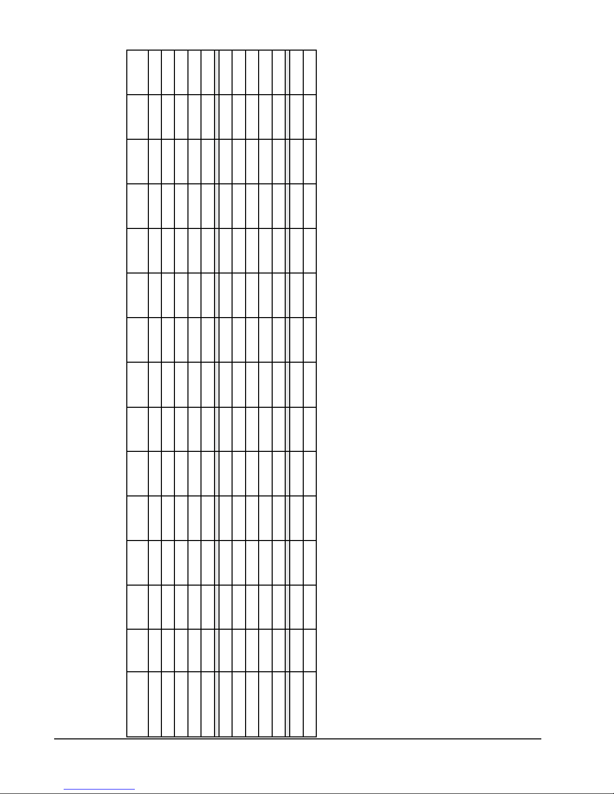
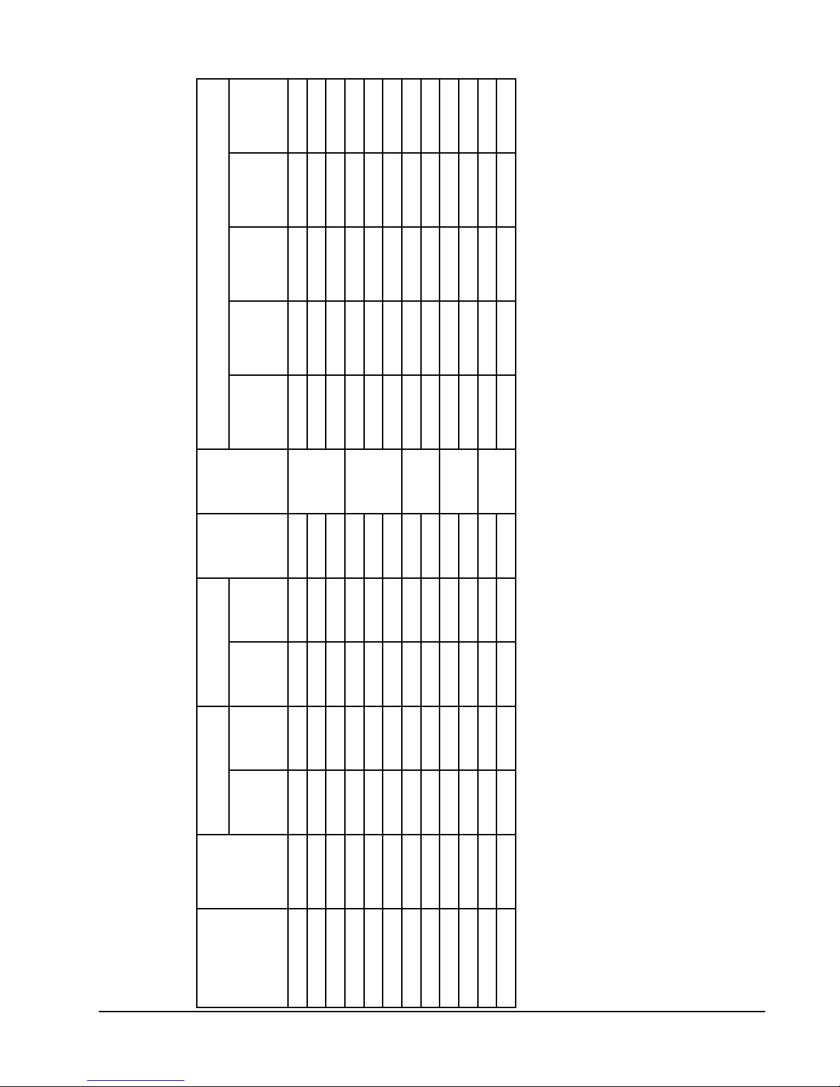
table 3
OPtIOnal FIelD InstalleD heater PacKaGes
Only tO be useD wIth the heat PumP mODels InDIcateD
X X
X X X
X X X
X
X X
Ph13242-a Ph13302-a Ph13363-a Ph13363-b Ph13422-a Ph13422-b Ph13422-c Ph13482-a Ph13482-b Ph13482-c Ph13602-a Ph13602-b Ph13602-c
Phase
Volts &
model
EHP323-A15 240/208-1
EHP323-B09 240/208-3 X
EHP323-A10 240/208-1 X X X
EHP323-A05 240/208-1 X X X
heater Package
Manual 2100-468J
Page 6 of 29
EHP323-B15 240/208-3
EHP513-A05 240/208-1 X X X
EHP513-A10 240/208-1 X X X
EHP513-A15 240/208-1
EHP513-B09 240/208-3 X X
EHP513-B15 240/208-3
EHP513-C09 460-3 X X X
EHP513-C15 460-3
Max. KW that can operate with Heat Pump on is 10 KW. 15 KW will operate during emergency heat.
Max. KW that can operate with Heat Pump on is 9 KW. 15 KW will operate during emergency heat.
Circuit B
Size
Wire
Ground
Field
Power
Wiring
Current
Protection
Max. Over
Min.
Circuit
Ampacity
table 4
OPtIOnal FIelD InstalleD electrIc heater table
Circuits
No. Field
Fuse
Heater
Internal
240/208V
Htr. Amps
@ 208 Volts
Htr. KW & Capacity
@ 240 Volts
Htr. KW & Capacity
KW BTUH KW BTUH
1 26/23 30/25 10/10 10
30/60
1 26/23 30/25 10/10 10
30/60
1 28/24 30/25 10/10 10
None
1 28/24 30/25 10/10 10
None
1 14 15 14 14
None
Phases
Unit Volts
Heater
Package
Model No.
EHP323-A05 240/208-1 5 17,100 3.75 12,800 20.8/18.1
EHP323-A10 240/208-1 10 34,100 7.50 26,000 41.6/36.2 1 53/46 60/50 6/8 10
EHP323-A15 240/208-1 15 51,200 11.25 38,400 62.5/54.1 1 79/68 80/70 4/4 8
EHP513-A05 240/208-1 5 17,100 3.75 12,800 20.8/18.1
EHP513-A10 240/208-1 10 34,100 7.50 26,000 41.6/36.2 1 53/46 60/50 6/8 10
EHP513-A15 240/208-1 15 51,200 11.25 38,400 62.5/54.1 1 79/68 80/70 4/4 8
EHP323-B09 240/208-3 9 30,700 6.75 23,000 21.7/18.7
EHP323-B15 240/208-3 15 51,200 11.25 38,400 36.2/31.2 1 46/39 50/40 8/8 10
EHP513-B09 240/208-3 9 30,700 6.75 23,000 21.7/18.7
EHP513-B15 240/208-3 15 51,200 11.25 38,400 36.2/31.2 1 46/39 50/40 8/8 10
EHP513-C09 480-3 9 30,700 10.8
EHP513-C15 480-3 15 51,200 18 1 28 30 10 12
and conductor wires in accordance with the national Electrical Code and all existing local codes.
Time delay fuses of HACR type circuit breakers must be used for 60 and smaller sizes. Standard fuses or circuit breakers are suitable for sizes 70 and
larger. 480V circuit breakers are not HACR type.
Based on wire suitable for 75 degree C. Other wiring materials must be rated for marked Minimum Circuit Ampacity or greater.
BaseduponTable250-95ofN.E.C.1993.SeeelectricdataforbasicheatpumpforCircuitAwiringspecicationrequirements.
NOTE: While this electrical data is presented as a guide, it is important to electrically connect properly sized fuses
Manual 2100-468J
Page 7 of 29

Return opening
Drain access
Supply opening
High voltage knockout
Low voltage knockout
access door
Control panel door
Heater package access panel
Compressor
Heater package knockout
A
E
C
D
L
W
B
F
Condenser air
Condenser air
intake grille
intake grille
access door
Blower motor
Condenser fan
G
47 11/16"
H
Unit Dimension Chart
MIS-2142 A
A C B C H (height) L (length) W (width) D E F G
PA/PH1324,1330,1336 5.875 32.875 13.875 32.875 26.25 53.25 38.125 23.25 1.125 1.375 35.625
PA/PH1342,1348,1360 9.875 37.875 15.875 37.875 33.25 55.25 42.375 30.25 1.5 2.375 38.125
Unit
Unit General Dimensions
Supply Size
Return Size
Unit Overall Dimensions
FIGure 1a
unIt DImensIOnal DrawInG
Manual 2100-468J
Page 8 of 29
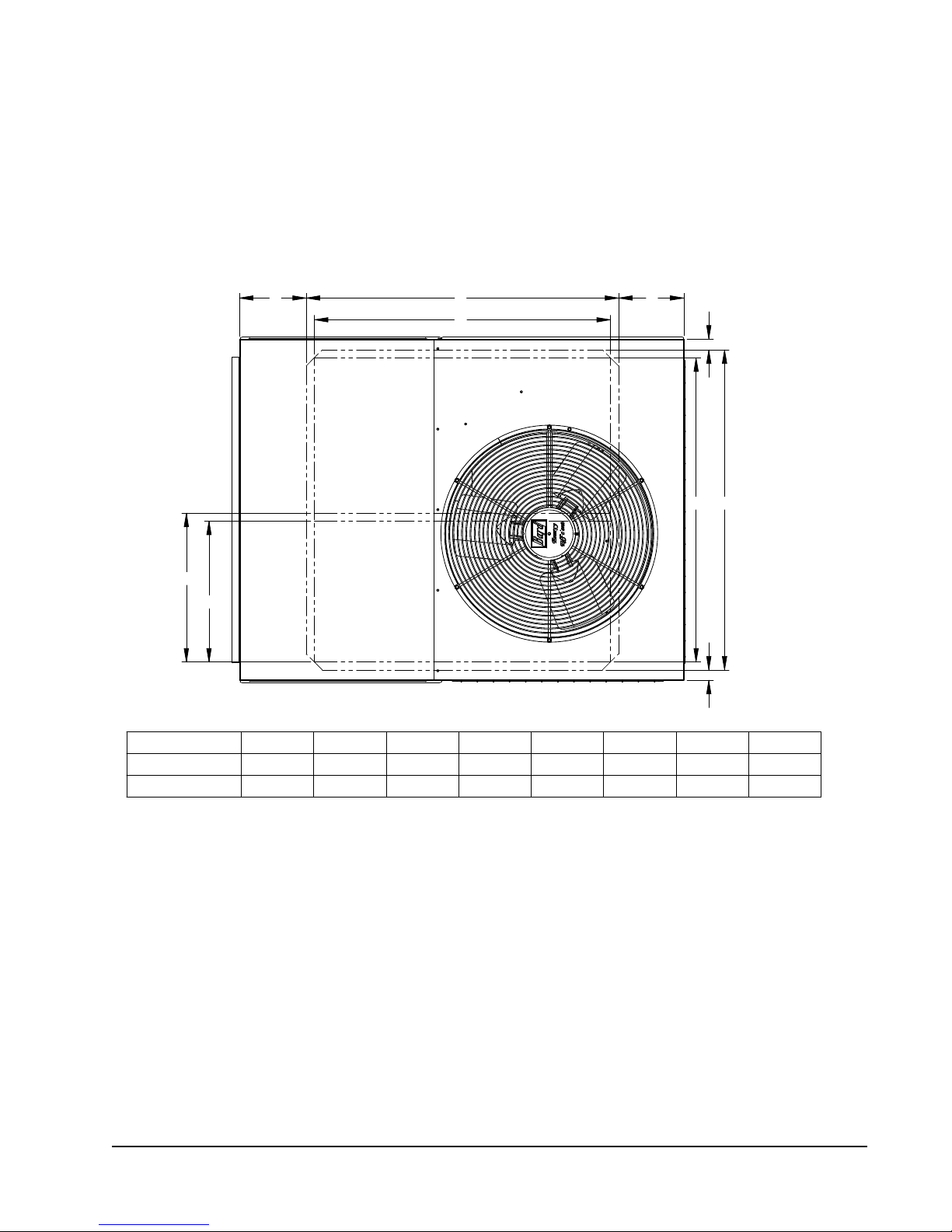
FIGure 1b
unIt DImensIOnal DrawInG
A B
C
G
H
UNIT A B C D E F GH
PA/PH1324, 1330, 1336 7 3/16" 3813/16" 36 3/4" 1 3/8" 33 5/8" 35 1/2" 183/16" 17 1/4"
PA/PH1342, 1348, 1360 8 3/16" 3913/16" 36 3/4" 1 3/8" 37 3/4" 39 3/4" 18 1/2" 17 1/2"
A
D
FE
D
MIS-3033
Manual 2100-468J
Page 9 of 29
 Loading...