

Bard PH13242-A, PH13422-A, PH13422-B, PH13422-C, PH13482-A Installation Instructions Manual
...Page 1

INSTALLATION INSTRUCTIONS
SINGLE PACKAGE
HEAT PUMPS
MODELS
PH13242-A PH13302-A
PH13363-A PH13363-B
PH13422-A PH13422-B
PH13422-C PH13482-A
PH13482-B PH13482-C
PH13602-A PH13602-B
PH13602-C
Bard Manufacturing Company, Inc.
Bryan, Ohio 43506
Since 1914 . . . Moving ahead, just as planned.
Manual : 2100-468J
Supersedes: 2100-468
File: Volume II Tab 11
Date: 07-25-12
I
Manual 2100-468J
Page 1 of 29
Page 2

CONTENTS
Getting Other Informations and Publications .........3
General Instructions
Important .................................................................4
Shipping Damage .....................................................4
General .................................................................4
Field-Installed Heater Packages (Optional) ..............4
Installation
Location ...............................................................10
Slab Mounting .........................................................10
Winter Installation ...................................................10
Typical Installations .........................................10 & 13
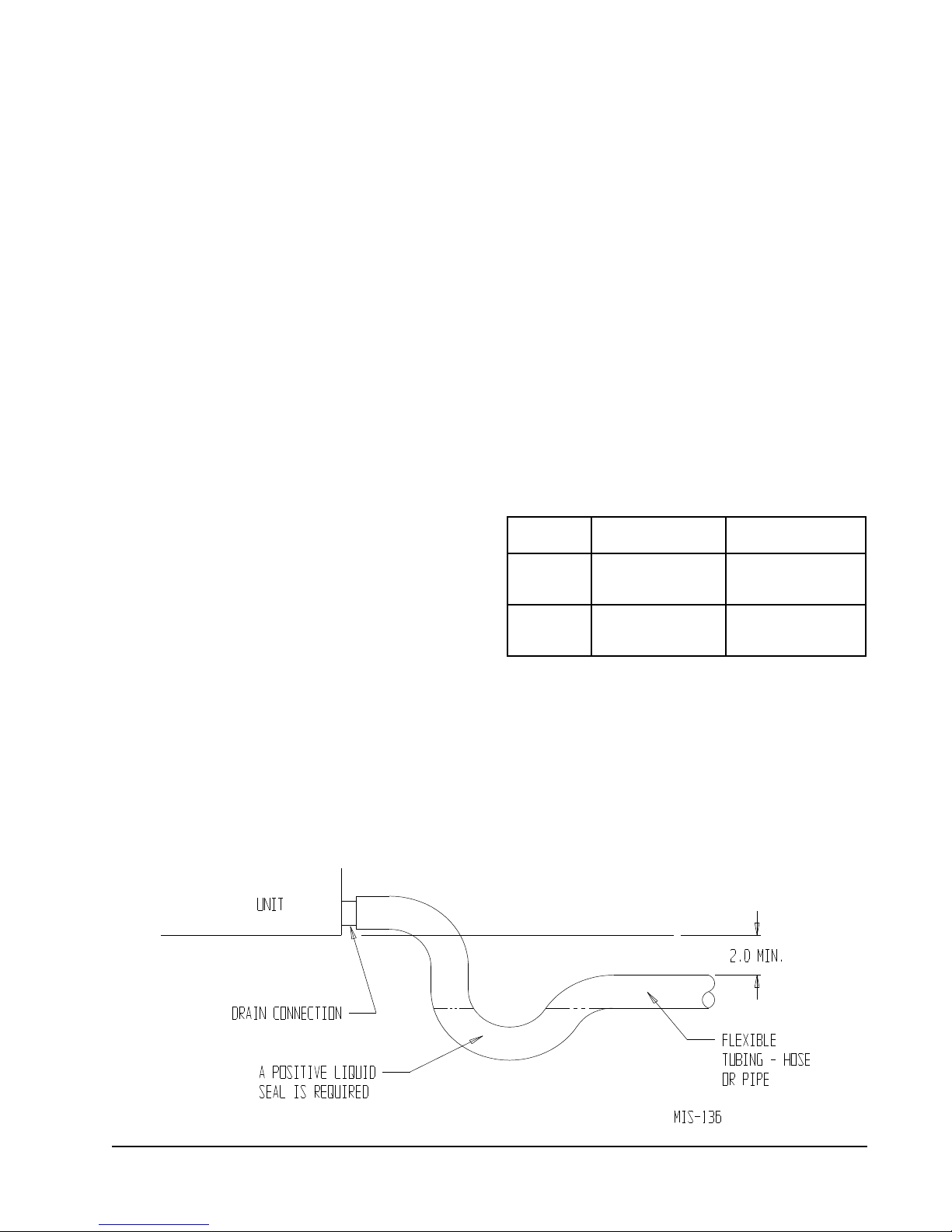
Condensate Drain Trap ...........................................13
Air Filters ...............................................................13
Thermostats ............................................................14
Wiring – Main Power ...............................................15
Wiring – 24V Low Voltage Control Circuit ...............15
Thermostat Indicator Lamps ...................................16
Emergency Heat Position .......................................16
Transformer Taps ....................................................16
Compressor Cutoff Thermostat and Outdoor ..........16
Figures
Figure 1A Unit Dimensional Drawing ........................8
Figure 1B Unit Dimensional Drawing ........................9
Figure 2 Slab Mounting at Ground Level .............. 11
Figure 3 Airow and Service Access
Clearances .............................................11
Figure 4 Elevated Mounting Platform ...................12
Figure 5 Condensate Drain Trap ..........................13
Figure 6 Low Voltage Wiring ................................15
Figure 7 Unit 24V Terminal Board (5–10 KW) ......16
Figure 8 Unit 24V Terminal Board (15–20 KW) ....17
Figure 9 Defrost Control Board ............................20
Figure 10 Fan Blade Setting ...................................24
Figure 11 Brazing Diagram ....................................27
Figure 12 Motor Connections .................................28
Figure 13 Wiring (Connections/Voltage) .................29
Start Up and Operation
General ...............................................................18
Topping Off System Charge ....................................18
Safety Practices ......................................................18
Start Up Notes ........................................................18
Three Phase Scroll Compressor Start Up
Information ..............................................................19
Sequence of Operation ...........................................19
Defrost Cycle ..................................................20 & 21
Troubleshooting
Solid State Heat Pump Control
Troubleshooting Procedure .....................................22
Troubleshooting Guide ............................................22
Checking Temperature Sensor Check Out .............23
Temperature vs. Resistance of
Temperature Sensor Chart ......................................23
Service
Service Hints ...........................................................24
Pressure Service Ports ...........................................24
R-410A Refrigerant Charge ....................................24
Fan Blade Settings .................................................24
Suction and Discharge Tube Brazing ......................27
Pressure Tables ..............................................24 & 25
Troubleshooting GE ECM Blower Motors ...28 & 29
Tables
Table 1 Rated CFM and ESP ................................4
Table 2 Electrical Data ..........................................5
Table 3 Optional Field Installed Heater
Packages .................................................6
Table 4 Opt. Field Installed Elec. Heater ..............7
Table 5 Required Filters ......................................13
Table 6 Heat Pump Thermostats ........................14
Table 7 Thermostat Wire Size .............................14
Table 8 Compressor Cutoff Thermostat
Wiring (5 - 10 KW) .................................17
Table 9 Compressor Cutoff Thermostat
Wiring (15 - 20 KW) ...............................17
Table 10 Troubleshooting......................................22
Table 11 Pressure Table - Cooling & Heating .......25
Table 12 Pressure Table - Cooling & Heating .......26
Table 13 Indoor Blower Performance ...................27
Manual 2100-468J
Page 2 of 29
Page 3

Getting Other Information and Publications
These publications can help you install the air conditioner
or heat pump. You can usually nd these at your local
library or purchase them directly from the publisher. Be
sure to consult current edition of each standard.
National Electrical Code ............................ANSI/NFPA 70
Standard for the Installation ....................ANSI/NFPA 90A
of Air Conditioning and Ventilating Systems
Standard
Heating and Air Conditioning Systems
Load Calculation for
Residential Winter and Summer Air Conditioning
Duct Design for Residential ....................ACCA Manual D
Winter and Summer Air Conditioning and Equipment
Selection
for Warm Air ............................ANSI/NFPA 90B
..............................ACCA Manual J
FOr mOre InFOrmatIOn, cOntact
these PublIshers:
ACCA Air Conditioning Contractors of America
1712 New Hampshire Ave. N.W.
Washington, DC 20009
Telephone: (202) 483-9370
Fax: (202) 234-4721
ANSI American National Standards Institute
11 West Street, 13th Floor
New York, NY 10036
Telephone: (212) 642-4900
Fax: (212) 302-1286
ASHRAE American Society of Heating Refrigerating,
and Air Conditioning Engineers, Inc.
1791 Tullie Circle, N.E.
Atlanta, GA 30329-2305
Telephone: (404) 636-8400
Fax: (404) 321-5478
NFPA National Fire Protection Association
Batterymarch Park
P.O. Box 9101
Quincy, MA 02269-9901
Telephone: (800) 344-3555
Fax: (617) 984-7057
Manual 2100-468J
Page 3 of 29
Page 4
General InstructIOns
ImPOrtant
The equipment covered in this manual is to be installed by
trained, experienced service and installation technicians.
Any heat pump is more critical of proper operating
charge and an adequate duct system than a straight air
conditioning unit. All duct work, supply and return ducts,
must be properly sized for the design airow requirement
of the equipment. ACCA is an excellent guide to proper
sizing. All duct work or portions thereof not in the
conditioned space should be properly insulated in order
to both conserve energy and prevent condensation or
moisture damage.
shIPPInG DamaGe
Upon receipt of equipment, the carton should be checked
for external signs of shipping damage. If damage is
found, the receiving party must contact the last carrier
immediately, preferably in writing, requesting inspection
by the carrier’s agent.
General
The refrigerant system is completely assembled and
charged. All internal wiring is complete.
The unit is designed for use with or without duct work.
Flanges are provided for attaching the supply and return
ducts.
These instructions and any instructions packaged with any
separate equipment required to make up the entire heat
pump system should be carefully read before beginning
the installation. Note particularly “Starting Procedure”
and any tags and/or labels attached to the equipment.
While these instructions are intended as a general
recommended guide, they do not supersede any national
and/or local codes in any way. Authorities having
jurisdiction should be consulted before the installation is
made.
FIelD InstalleD heater PacKaGes
(OPtIOnal)
These packaged heat pumps are manufactured without
supplementary electric heaters. Supplementary heaters are
available for simple, fast eld installation.
A separate power circuit is required for the supplementary
heaters.
IMPORTANT: Refer to Table 1 when designing duct
work for maximum available static pressure with heater
installed.
Refer to Tables 2 and 4 for proper application information
on all available heater combinations and what units they
can be used with. It also shows the applicable circuit
ampacities, fuse size, and wire size for each heater
combination.
These instructions explain the recommended method to
install the air cooled self-contained unit and the electrical
wiring connections to the unit.
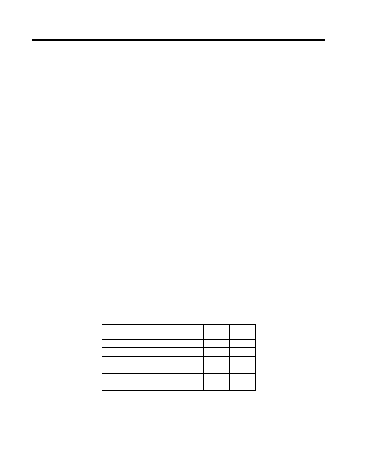
rateD cFm anD external statIc Pressure (esP)
model
no.
PH1324 800 Note 0.10 0.50
PH1330 1000 Note 0.15 0.50
PH1336 1100 Note 0.15 0.50
PH1342 1450 Note 0.15 0.50
PH1348 1550 Note 0.20 0.50
PH1360 1750 Note 0.20 0.50
rated
cFm
NOTE: Motor will adjust to deliver rated airow.
table 1
recommended
Airow Range
rated
esP
max.
esP
Manual 2100-468J
Page 4 of 29
Page 5

460-60-3
230/208-60-1 230/208-60-3
460-60-3
230/208-60-1 230/208-60-3
460-60-3
table 2
electrIcal Data
230/208-60-1 230/208-60-1 230/208-60-1 230/208-60-3 230/208-60-1 230/208-60-3
electric rating –
60 hz – circuit a
model Ph13242-a Ph13302-a Ph13363-a Ph13363-b Ph13422-a Ph13422-b Ph13422-c Ph13482-a Ph13482-b Ph13482-c Ph13602-a Ph13602-b Ph13602-c
Operating Voltage Range 197 - 253 197 - 253 197 - 253 187 - 253 197 - 253 187 - 253 414-506 197 - 253 187 - 253 414-506 197 - 253 187 - 253 414-506
Fan motor and condenser
Fan Motor – HP/RPM 1/6 / 825 1/6 / 825 1/6 / 825 1/6 / 825 1/4 / 825 1/4 / 825 1/4 / 825 1/4 / 825 1/4 / 825 1/4 / 825 1/4 / 825 1/4 / 825 1/4 / 825
Fan Motor Amps 1.1 1.1 1.1 1.1 1.5 1.5 1.5 1.5 1.5 1.5 1.5 1.5 1.5
Minimum Circuit Ampacity 20 22 27 18 33 25 12 36 29 14 39 26 17
BCSC 13 14 17.5 11 21 15 8 22 14 8 26 16 9
Field Wire Size * 12 10 10 12 10 10 14 8 10 12 8 10 10
Ground Wire Size 12 10 8 12 10 10 14 8 10 14 8 10 12
Delay Fuse – Max. ** 30 30 40 25 50 35 15 50 40 20 60 40 25
Total unit Amps – 230/208 11.2/12.2 14.8/16.3 19.4/21.9 13.9/15.4 21.9/22.9 17.1/17.9 10.4 24.7/26.6 18.0/19.2 10.7 25.3/28.9 17.7/19.9 11.9
compressor – circuit a
Compressor Type Scroll Scroll Scroll Scroll Scroll Scroll Scroll Scroll Scroll Scroll Scroll Scroll Scroll
Volts 230/208 230/208 230/208 230/208 230/208 230/208 460 230/208 230/208 460 230/208 230/208 460
Rated Load Amps 8/9 11/12.5 15/17.5 9.5/11 16.1/17.1 11.3/12.0 7.7 18.7/20.6 12.0/13.2 7.7 19.3/22.9 11.7/13.9 8.6
Lock Rotor Amps 58.3/58.3 73/73 79/79 88/88 115/115 115/115 50 117/117 83.1/83.1 50 134/134 110/110 52
Fan – Dia./CFM 24"/2800 24"/2600 24"2600 24"/2600 24"/3400 24"/3400 24"/3400 24"/3400 24"/3400 24"/3400 24"/3400 24"/3400 24"/3400
motor and evaporator
Blower Motor – HP/RPM 1/3 ECM 1/2 ECM 1/2 ECM 1/2 ECM 1/2 ECM 1/2 ECM 1/2 ECM 3/4 ECM 3/4 ECM 3/4 ECM 3/4 ECM 3/4 ECM 3/4 ECM
Blower Motor – Amps 2.1 2.7 3.3 3.3 3.9 3.9 3.9 4.5 4.5 4.5 5.0 5.0 5.0
CFM Cooling 800 1000 1000 1000 1450 1450 1450 1550 1550 1550 1750 1750 1750
Charge (R-410A oz.) 75 136 136 136 170 170 160 180 180 160 190 190 160
Shipping Weight (pounds) 360 410 410 410 440 440 490 440 440 500 450 450 500
* 75 degree C copper wire
** Maximum time delay fuse of HACR type circuit breaker
Manual 2100-468J
Page 5 of 29
Page 6
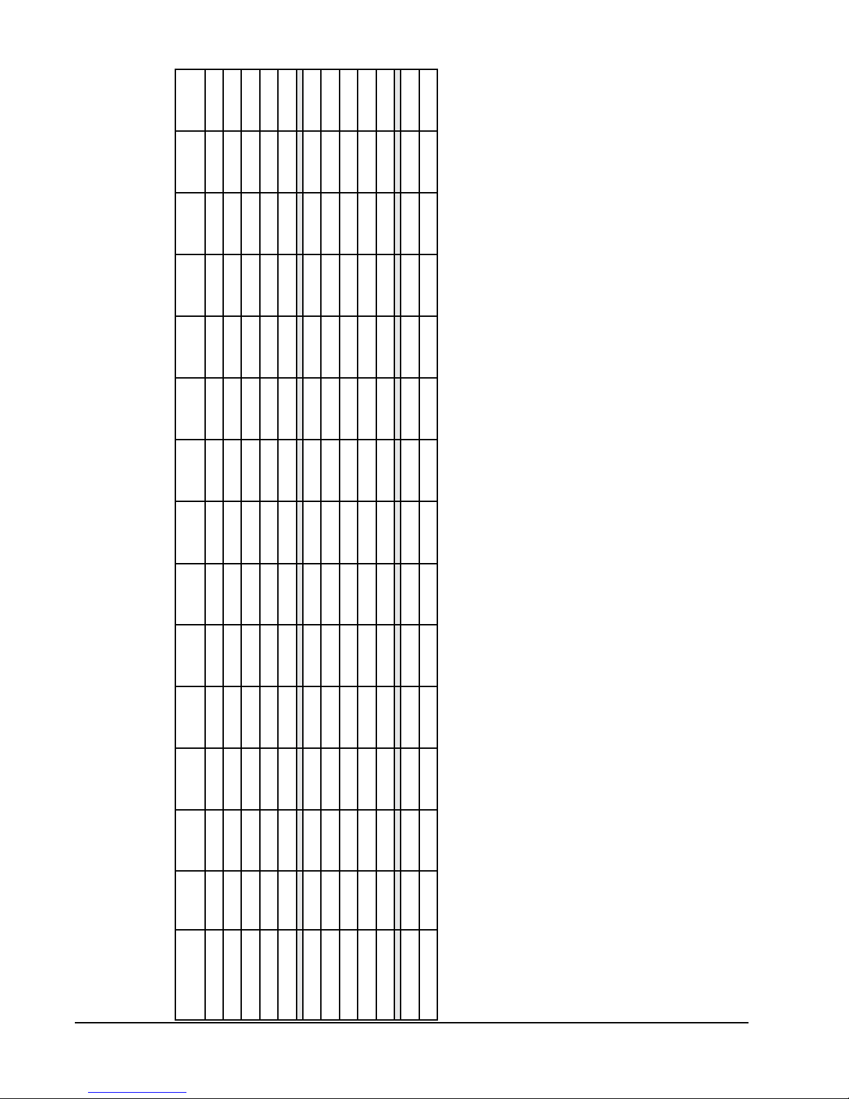
table 3
OPtIOnal FIelD InstalleD heater PacKaGes
Only tO be useD wIth the heat PumP mODels InDIcateD
X X
X X X
X X X
X
X X
Ph13242-a Ph13302-a Ph13363-a Ph13363-b Ph13422-a Ph13422-b Ph13422-c Ph13482-a Ph13482-b Ph13482-c Ph13602-a Ph13602-b Ph13602-c
Phase
Volts &
model
EHP323-A15 240/208-1
EHP323-B09 240/208-3 X
EHP323-A10 240/208-1 X X X
EHP323-A05 240/208-1 X X X
heater Package
Manual 2100-468J
Page 6 of 29
EHP323-B15 240/208-3
EHP513-A05 240/208-1 X X X
EHP513-A10 240/208-1 X X X
EHP513-A15 240/208-1
EHP513-B09 240/208-3 X X
EHP513-B15 240/208-3
EHP513-C09 460-3 X X X
EHP513-C15 460-3
Max. KW that can operate with Heat Pump on is 10 KW. 15 KW will operate during emergency heat.
Max. KW that can operate with Heat Pump on is 9 KW. 15 KW will operate during emergency heat.
Page 7
Circuit B
Size
Wire
Ground
Field
Power
Wiring
Current
Protection
Max. Over
Min.
Circuit
Ampacity
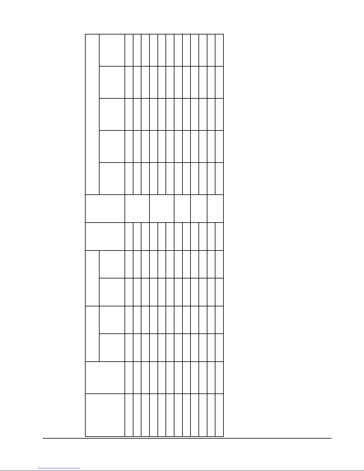
table 4
OPtIOnal FIelD InstalleD electrIc heater table
Circuits
No. Field
Fuse
Heater
Internal
240/208V
Htr. Amps
@ 208 Volts
Htr. KW & Capacity
@ 240 Volts
Htr. KW & Capacity
KW BTUH KW BTUH
1 26/23 30/25 10/10 10
30/60
1 26/23 30/25 10/10 10
30/60
1 28/24 30/25 10/10 10
None
1 28/24 30/25 10/10 10
None
1 14 15 14 14
None
Phases
Unit Volts
Heater
Package
Model No.
EHP323-A05 240/208-1 5 17,100 3.75 12,800 20.8/18.1
EHP323-A10 240/208-1 10 34,100 7.50 26,000 41.6/36.2 1 53/46 60/50 6/8 10
EHP323-A15 240/208-1 15 51,200 11.25 38,400 62.5/54.1 1 79/68 80/70 4/4 8
EHP513-A05 240/208-1 5 17,100 3.75 12,800 20.8/18.1
EHP513-A10 240/208-1 10 34,100 7.50 26,000 41.6/36.2 1 53/46 60/50 6/8 10
EHP513-A15 240/208-1 15 51,200 11.25 38,400 62.5/54.1 1 79/68 80/70 4/4 8
EHP323-B09 240/208-3 9 30,700 6.75 23,000 21.7/18.7
EHP323-B15 240/208-3 15 51,200 11.25 38,400 36.2/31.2 1 46/39 50/40 8/8 10
EHP513-B09 240/208-3 9 30,700 6.75 23,000 21.7/18.7
EHP513-B15 240/208-3 15 51,200 11.25 38,400 36.2/31.2 1 46/39 50/40 8/8 10
EHP513-C09 480-3 9 30,700 10.8
EHP513-C15 480-3 15 51,200 18 1 28 30 10 12
and conductor wires in accordance with the national Electrical Code and all existing local codes.
Time delay fuses of HACR type circuit breakers must be used for 60 and smaller sizes. Standard fuses or circuit breakers are suitable for sizes 70 and
larger. 480V circuit breakers are not HACR type.
Based on wire suitable for 75 degree C. Other wiring materials must be rated for marked Minimum Circuit Ampacity or greater.
BaseduponTable250-95ofN.E.C.1993.SeeelectricdataforbasicheatpumpforCircuitAwiringspecicationrequirements.
NOTE: While this electrical data is presented as a guide, it is important to electrically connect properly sized fuses
Manual 2100-468J
Page 7 of 29
Page 8

Return opening
Drain access
Supply opening
High voltage knockout
Low voltage knockout
access door
Control panel door
Heater package access panel
Compressor
Heater package knockout
A
E
C
D
L
W
B
F
Condenser air
Condenser air
intake grille
intake grille
access door
Blower motor
Condenser fan
G
47 11/16"
H
Unit Dimension Chart
MIS-2142 A
A C B C H (height) L (length) W (width) D E F G
PA/PH1324,1330,1336 5.875 32.875 13.875 32.875 26.25 53.25 38.125 23.25 1.125 1.375 35.625
PA/PH1342,1348,1360 9.875 37.875 15.875 37.875 33.25 55.25 42.375 30.25 1.5 2.375 38.125
Unit
Unit General Dimensions
Supply Size
Return Size
Unit Overall Dimensions
FIGure 1a
unIt DImensIOnal DrawInG
Manual 2100-468J
Page 8 of 29
Page 9
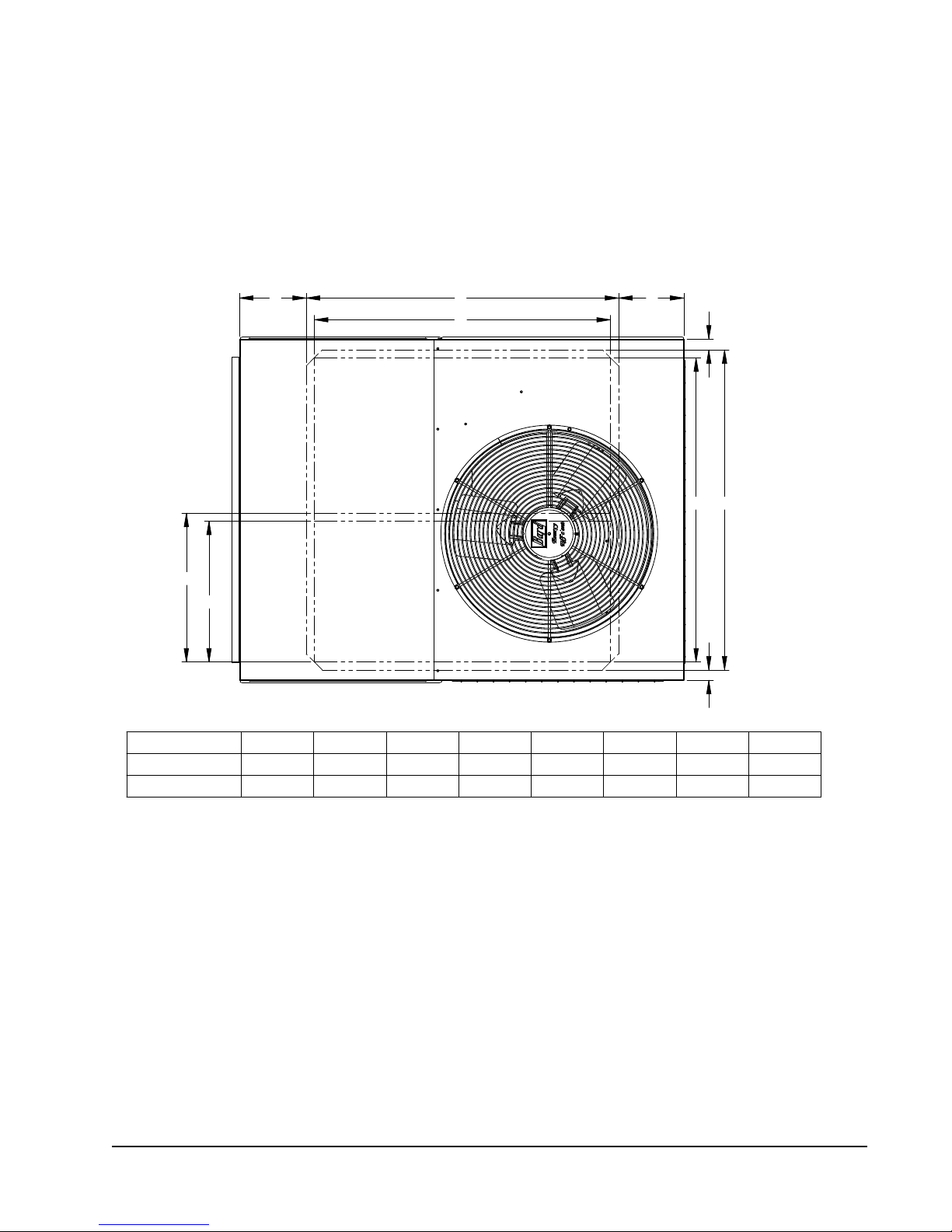
FIGure 1b
unIt DImensIOnal DrawInG
A B
C
G
H
UNIT A B C D E F GH
PA/PH1324, 1330, 1336 7 3/16" 3813/16" 36 3/4" 1 3/8" 33 5/8" 35 1/2" 183/16" 17 1/4"
PA/PH1342, 1348, 1360 8 3/16" 3913/16" 36 3/4" 1 3/8" 37 3/4" 39 3/4" 18 1/2" 17 1/2"
A
D
FE
D
MIS-3033
Manual 2100-468J
Page 9 of 29
Page 10

InstallatIOn
lOcatIOn
General
The unit must be located outside, or in a well ventilated
area. It must not be in the space being heated or cooled. A
sound absorbing material should be considered if the unit
is to be installed in such a position or location that might
cause transmission of sound or vibration to the living area
or adjacent buildings.
slab mOuntInG
In areas where winter temperatures DO NOT go below
32°F for periods over twelve hours, the unit may be slab
mounted at grade level.
level, install on a concrete slab at least four inches above
nished grade level. Slab should have a slope tolerance
away from the building structure of at lease ¼ inch per
foot, while being level from side to side. This will prevent
ice buildup under the unit during defrost cycles. Place
slab in a location where runoff water from higher ground
will not collect around unit. See Figure 2.
A minimum of 24 inches should be provided between the
coil inlet and any building surfaces. Provide a minimum
of three feet clearance on the service access side of the
unit. See Figure 3.
When a unit is installed in areas where low ambient
temperatures or strong winter winds exist, it should be
placed so prevailing winter winds are not in direct line
with the heat pump coil. If this is not possible, a wind
barrier should be constructed. Place barrier 24 inches
from the coil inlet side of the unit and in the direction of
prevailing winds. Size barrier at least the same height and
width as the unit. This may be necessary on ground level
installations, also. See Figure 3.
wInter InstallatIOn belOw 32°F
In areas where winter conditions go below 32°F for
extended periods, the unit must be elevated above
the mounting surface to prevent snowfall or defrost
ice accumulation from interfering with the operation
of the unit. A minimum of twelve inch elevation is
recommended, while greater elevation may be required for
areas of high snow accumulation. Poured concrete, steel
framework, brick, cement block, etc., can be utilized to
construct a suitable raised mounting platform. See
Figure 4.
When installing unit at grade
tyPIcal InstallatIOns
1.
rOOF mOunteD
sturdy base on the roof of the building. Return air
to the unit is brought through a single return grille
(grilles with built-in lters are best since they enable
easy access for lter changing). Return air ducts
are attached to the lower section of the front panel.
Supply air is brought from the unit to attic duct work
or to a furred down hall. Supply air duct is attached to
the top of the front panel.
CAUTION: All outdoor duct work must be thoroughly
insulated and weatherproofed. All attic duct
work must be thoroughly insulated. Two inch
thick insulation with suitable vapor barrier is
recommended for both outdoor and attic runs.
In roof top installation, as in all installations, the heat
pump must be level from side to side. However, the
unit should have a pitch along the length to assure
complete external drainage of precipitation and of
defrost condensate.
crawl sPace
2.
space must be well insulated and provided with a
vapor barrier. In addition, the crawl space must be
thoroughly ventilated and provided with a good vapor
barrier as a ground cover. It is most desirable to install
the unit outdoors rather than inside the crawl space,
so that it will be readily accessible for service. In
addition, it is necessary to dispose of the condensate
from the outdoor coil on the heating cycle, and this is
virtually impossible with the unit installed inside the
crawl space.
slab mOunteD at GrOunD leVel
3.
type installation is ideal for homes with a slab oor
construction where a roof mounted unit is not desired.
The supply and return duct work can be run through a
furred closet space.
thrOuGh the wall
4.
requires a suitable framework to be fabricated capable
of withstanding the unit weight. Normally the unit
will be insulated so as to minimize supply and return
duct work.
– The unit is mounted on a
– Duct work installed in crawl
– This
– This type installation
Manual 2100-468J
Page 10 of 29
Page 11
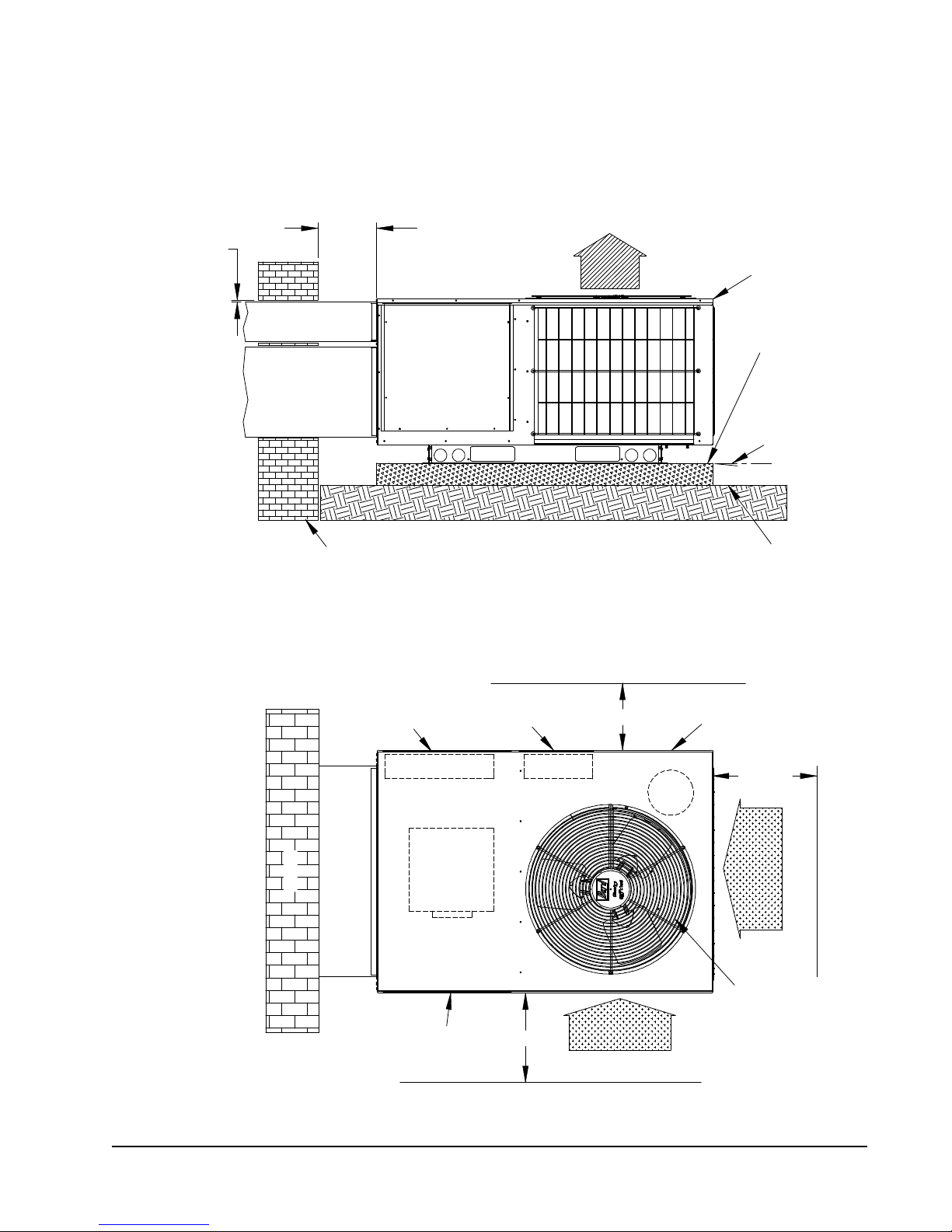
FIGure 2
36" min.
24" min.
24" min.
The distance between
1 inch clearance
Access
Air Inlet
Comp-
Nearest Structure
Air Inlet
Supply and Return Ducts
Nearest Structure
Nearest Structure
Building
Control Panel
Access
Control Panel
Access
Heater Package
Access
Blower Service
and
ressor
Blower Motor
Heater Package
Blower
Compressor
from top.
units only).
Condenser fan
and motor access
above fan.
Leave 60" min.
Side
View
View
Top
between duct and
any combustible
material if distance
between outside
wall and unit is less
than 3 feet (needed
on electric heat
MIS-2143 A
Mounting Slab
Ground Level
Package Unit
Supply Duct
from building
Return Duct
requirements.
outside wall and unit
Air Outlet
varies with installation
1/4 inch per foot
slope away
Building
slab mOuntInG at GrOunD leVel
FIGure 3
aIrFlOw anD serVIce access clearances
Manual 2100-468J
Page 11 of 29
Page 12
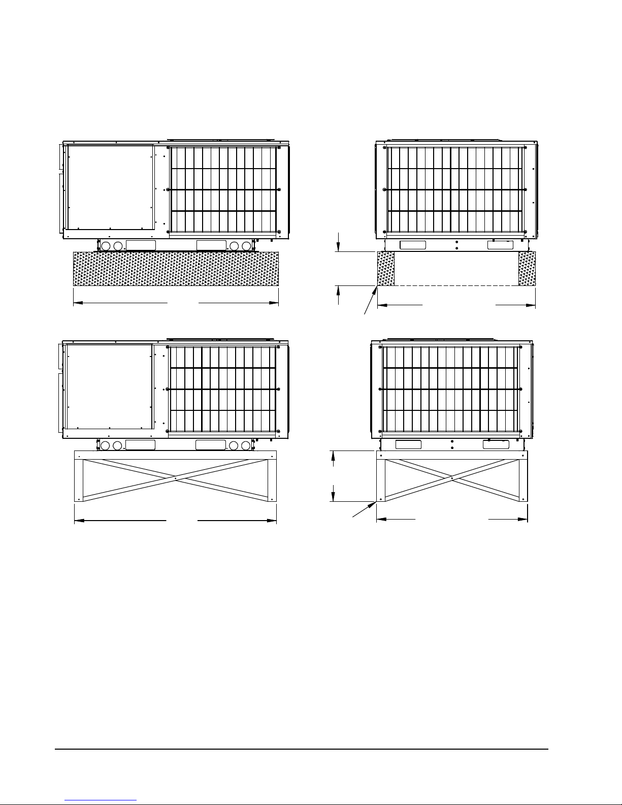
FIGure 4
Both legs must rest
on surface of platform
32°F or lower climate
12" min. if in
48" min.
48" min.
32°F or lower climate
12" min. if in
on surface of platform
Both legs must rest
Platform can be as
shown or solid
Poured concrete,
brick, or block
Metal frame
MIS-2144 A
eleVateD mOuntInG PlatFOrms
Manual 2100-468J
Page 12 of 29
Page 13
Other InstallatIOns
5.
– Many other
installations are possible with the packaged heat
pump. No matter what the installation, always
consider the following facts:
A. Insure that the discharge air is not obstructed
in any way so as to cause operation difculties.
B. The indoor coil drain pan is equipped with a
coupling that must be piped thr ough a condensate
drain trap to a suitable drain.
C. Always mount the unit is such a position that it
may be easily reached for servicing and
maintenance.
D. Insure that the unit is clear so that proper air ow
over the outdoor coil will be maintained.
If this unit is operated in cooling below a 55° outdoor
ambient temperature, the installation of low ambient
controls (CMH-15) to unit is required.
cOnDensate DraIn traP
It is very important to provide a trap in the condensate
drain line to allow a positive liquid seal in the line and
assure correct drainage from the coil condensate pan.
Install condensate drain trap shown in Figure 5. Use
drain connection size or larger. Do not operate unit
without trap. Unit must be level or slightly inclined
toward drain.
With a trap installed on a unit located in an unconditioned
area, water in the trap may freeze. It is recommended
that the trap material be of a type that will allow for
expansion of water when it freezes.
aIr FIlters
Air lters for the return air side of the system are not
provided as part of the various types of applications for
these models, and must be eld supplied and installed as
part of the nal installation.
Prior thought should be given to return air location and
placement of the air lter(s). The air lter(s) must be of
adequate size and readily accessible to the operator of the
equipment. Filters must be adequate in size and properly
maintained for proper operation. If this is not done,
excessive energy use, poor performance, and multiple
service problems will result. It is impossible to oversize
air lters. Generous sizing will result in cleaner air and
coils as well as lower operating costs and extend the time
between required changes. Table 5 shows minimum lter
areas and recommended lter sizes. Actual lter sizes
can vary with the installation due to single or multiple
returns utilizing a lter/grille arrangement or being placed
immediately ahead of the indoor coil face in the return air
duct.
table 5
FIlters requIreD anD sIze
model no.
PH1324
PH1330
PH1336
PH1342
PH1348
PH1360
minimum Filter
Free area
403SquareInches
(2.8SquareFeet)
473SquareInches
(3.3SquareFeet)
NOTE: If roof hood accessory is to be used, information
on air lters may be found under that heading in
this manual. Air lters are supplied as part of
that package.
minimum
recommended size
(2) 14 x 20 x 1
(2) 16 x 20 x 1
FIGure 5
cOnDensate DraIn traP
Manual 2100-468J
Page 13 of 29
Page 14
thermOstats
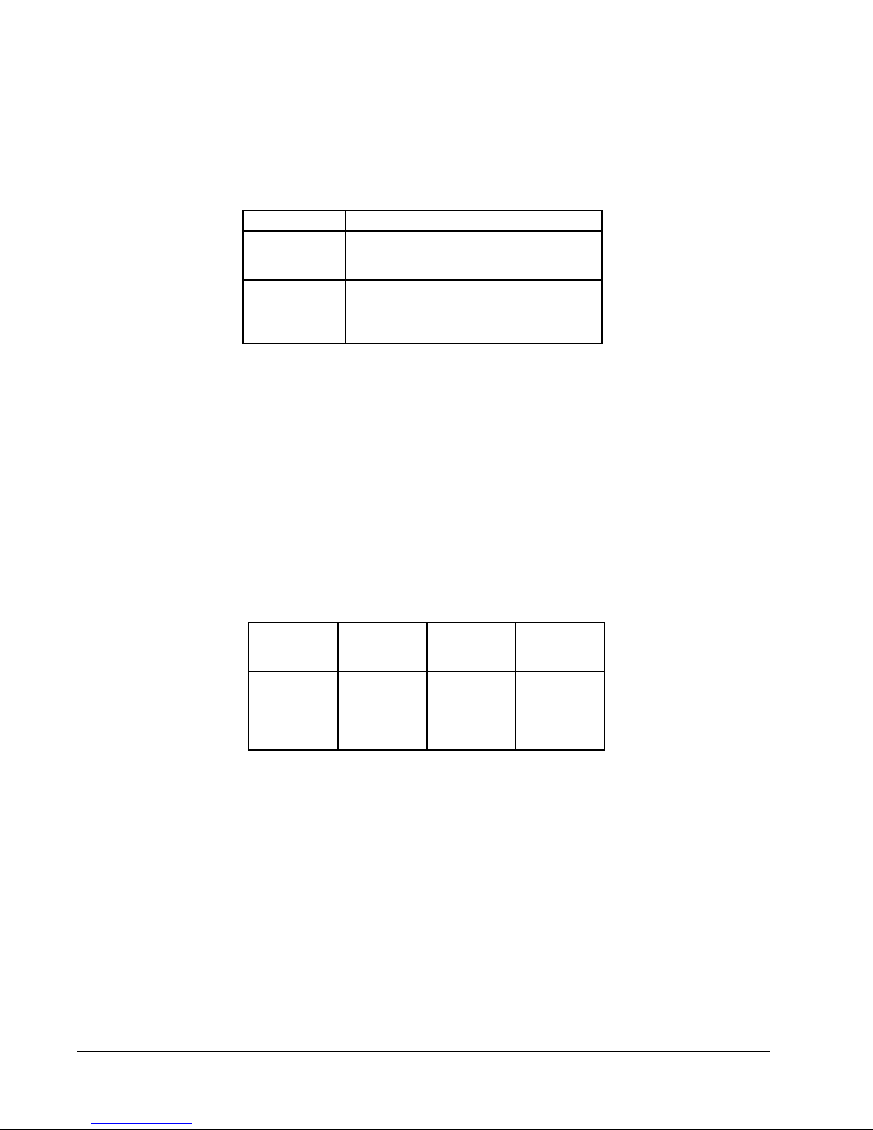
See specic wiring information for the different models, heater KWs, and voltages.
table 6
heat PumP thermOstats
thermostat Predominant Features
8403-058
(TH5220D1151)
8403-060
(1120-445)
IMPORTANT NOTE: Only the thermostat and subbase combinations as shown above will work with this equipment.
The thermostat and subbase MUST be matched, and correct operation can be assured only by proper selection
and application of these parts. The above combinations incorporate the following features: Man-Auto fan
switch, Off-Heat-Cool-Em. Heat Switch.
NOTE: All thermostats specied maintain the reversing valve energized when switched into heating mode (does not
cycle with demand).
2 stage Cool; 2 stage Heat
Electronic Non-Programmable
Auto or Manual changeover
3 stage Cool; 3 stage Heat
Programmable/Non-Programmable Electronic
HP or Conventional
Auto or Manual changeover
table 7
thermOstat wIre sIze
transformer
Va
55 2.3 20
Fla
wire
Gauge
18
16
14
12
maximum
length
in Feet
45
60
100
160
250
Manual 2100-468J
Page 14 of 29
Page 15
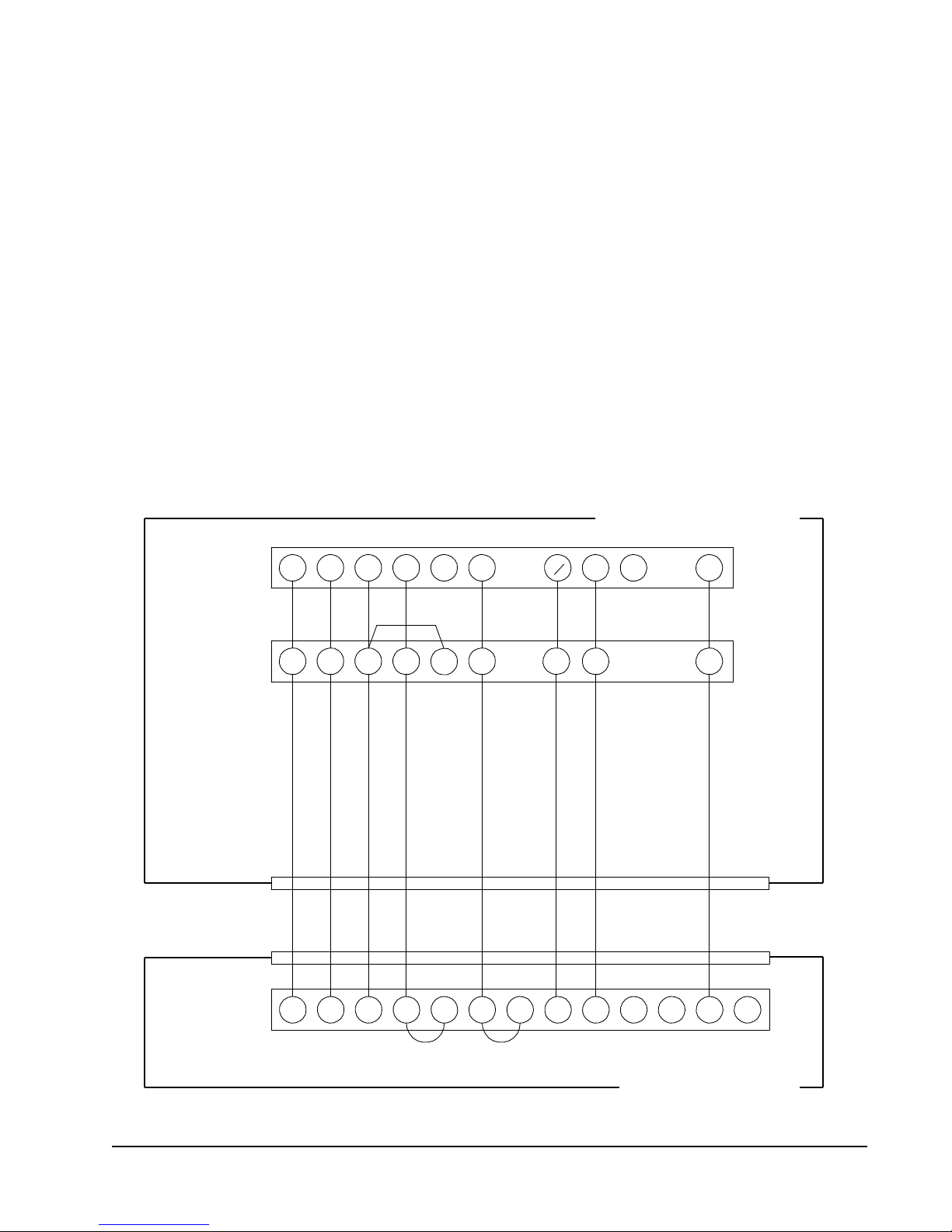
wIrInG – maIn POwer
O/B
W2
MIS-2150 A
Low Voltage Wiring
D1
DH
A
AUX
Unit Control Panel
Block
Y
C
G R Y1 B
W1 E
L W3
Y1C
G R
Y2 W2
L
LEO/B
RC
R
GC
Y
1120-445
Thermostat Subbase
TH5220D1151
Terminal
Unit 24V
W1
E
Refer to the unit rating plate for wire sizing information
and maximum fuse size. Each outdoor unit is marked with
a “Minimum Circuit Ampacity”. This means that the eld
wiring used must be sized to carry that amount of current.
If eld installed heaters are added to the basic unit, a
second separate power supply circuit will be required.
The heater rating plate located adjacent to the basic unit
rating plate will show the appropriate circuit ampacity fuse
size, etc. (Also see “Electrical Data” on pages 5 and 7.)
All models are suitable for connection with copper wire
only. These instructions must be adhered to. Refer to the
National Electrical Code for complete current carrying
capacity data on the various insulation grades of wiring
material.
FIGure 6
lOw VOltaGe wIrInG
The unit rating plate lists a “Maximum Time Delay Fuse”
or “HACR” type circuit breaker that is to be used with
the equipment. The correct size must be used for proper
circuit protection and also to assure that there will be no
nuisance tripping due to the momentary high starting
current of the compressor.
wIrInG – 24V lOw VOltaGe cOntrOl
cIrcuIt
Eight (8) wires should be run from thermostat subbase to
the 24V terminal board in the unit. A ten conductor,
18 gauge copper, color-coded thermostat cable is
recommended.
Figure 6.
The connection points are shown in
Manual 2100-468J
Page 15 of 29
Page 16
thermOstat InDIcatOr lamPs
MIS-2151
D1
Outdoor Fan Motor
Control
Yellow
Yel/Brn
Terminal
Outdoor
Block
Y
C
G
R
Y1
B
DH
Black
Safety
W1
Compressor
Factory Jumper
W2
Yellow
E
W3
Unit C ontrol Panel
Unit 24V
Heat
Brown
Remove
Relay
used as
"Y to Y1"
Yel/Brn
Cutoff
L
Blue
Thermostat
Heat Pump
Control
(Partially Shown)
Low Ambient
Optional Field Wiring
2
1
3
5
1
3
2
4
6
L
Note: Factory set on 60 min.
cycle. Reconnect on 30 min.
for 30 min. cycle or 90 min.
for 90 min. cycle.
SPEEDUPJMPSEN
306090
NC
NO
COM
R
W2
R
Y
CC
L1
C
C
LO
B
RV
SENSOR
OFM
The red lamp marked “EM. HT.” comes on and stays on
whenever the system switch is placed in Em. Ht. position.
The green lamp marked “Check” will come on if there is
any problem that prevents the compressor from running
when it is supposed to be.
emerGency heat POsItIOn
The operator of the equipment must manually place the
system switch in this position. This is done when there is
a known problem with the outdoor section, or when the
green “Check” lamp comes on indicating a problem.
transFOrmer taPs
230/208V, 1 phase and 3 phase equipment employ dual
primary voltage transformers. All equipment leaves the
factory wired on 240V tap. For 208V operation, reconnect
from 240V to 208V tap. The acceptable operating voltage
range for the 240 and 208V taps are:
TAP RANGE
240 253 – 216
208 220 – 187
NOTE: The voltage should be measured at the eld
power connection point in the unit and while
the unit is operating at full load (maximum
amperage operating condition).
cOmPressOr cutOFF thermOstat
and OutDOOr thermOstat wIrInG
Heat pump compressor operation at outdoor temperatures
below 0°F are neither desirable not advantageous in
terms of efciency. Since most equipment at time of
manufacture is not designated for any specic destination
of the country and most of the equipment is installed in
areas not approaching the lower outdoor temperature
range, the compressor cutoffs are not factory installed.
Outdoor thermostats are available to hold off various banks
of electric heat until needed as determined by outdoor
temperature. The set point of either type of thermostat is
variable with geographic region and sizing of the heating
equipment to the structure. Utilization of the Heating
Application Data and the heat loss calculation of the
building are useful in determining the correct set points.
Refer to Installation Instructions of CMH-14 Outdoor
Thermostat Kit for more information.
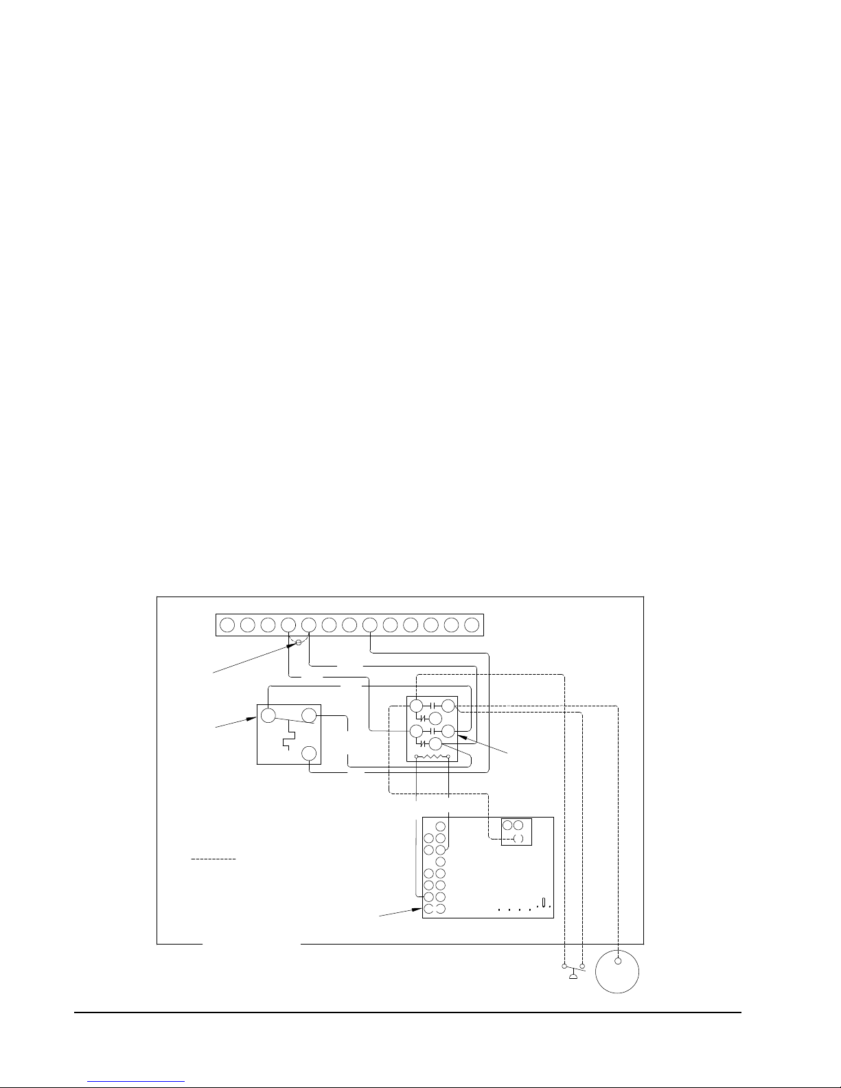
FIGure 7
unIt 24V termInal bOarD (5 — 10 Kw)
Manual 2100-468J
Page 16 of 29
Page 17
cOmPressOr cutOFF thermOstat
D1
Control
Optional Field Wiring
Outdoor
DH
Y1
Factory Jumper
Safety
Compressor
Block
Y
C
G
R
used as
B
W1
W3
Yel/Brn
W2
Outdoor Fan Motor
Brown
L
Heat
Unit C ontrol Panel
Unit 24V
Remove
Cutoff
Relay
Yellow
"Y to Y1"
Yel/Brn
Blue
Yellow
E
Terminal
Black
Thermostat
Heat Pump
Control
(Partially Shown)
Low Ambient
MIS-2152
2
1
3
5
1
3
2
4
6
L
Note: Factory set on 60 min.
cycle. Reconnect on 30 min.
for 30 min. cycle or 90 min.
for 90 min. cycle.
SPEEDUPJMPSEN
306090
NC
NO
COM
R
W2
R
Y
CC
L1
C
C
LO
B
RV
SENSOR
OFM
wIrInG (5 — 10 Kw) (FIGure 7)
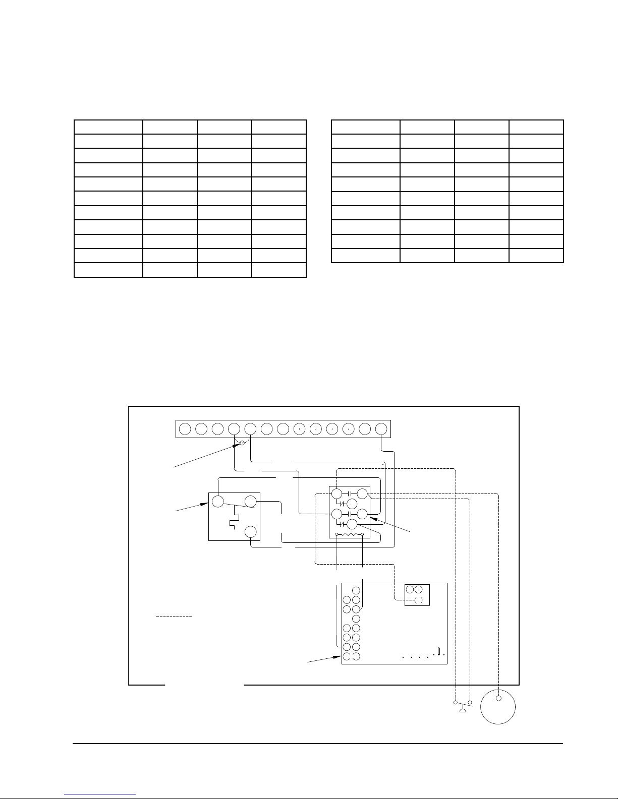
cOmPressOr cutOFF thermOstat
wIrInG (15 — 20 Kw ) (FIGure 8)
table 8
5 — 10 Kw
model Kw Volts Phase
PH13242-A 0, 5, 10 230 1
PH13302-A 0, 5, 10 230 1
PH13363-A 0, 5 230 1
PH13363-B 0, 9 230 3
PH13422-A 0, 5, 10 230 1
PH13422-B, -C 0, 9 230/460 3
PH13482-A 0, 5, 10 230 1
PH13482-B, -C 0, 9 230/460 3
PH13602-A 0, 5, 10 230 1
PH13602-B, -C 0, 9 230/460 3
unIt 24V termInal bOarD (15 thrOuGh 20 Kw)
table 9
15 — 20 Kw
model Kw Volts Phase
PH13302-A 15 230 1
PH13363-A 15 230 1
PH13363-B 15 230 3
PH13422-A 15 230 1
PH13422-B, -C 15 230/460 3
PH13482-A 15 230 1
PH13482-B, -C 15 230/460 3
PH13602-A 15 230 1
PH13602-B, -C 15 230/460 3
FIGure 8
Manual 2100-468J
Page 17 of 29
Page 18

start uP
These units require R-410A refrigerant and Polyol Ester.
General:
1. Use separate service equipment to avoid cross
contamination of oil and refrigerants.
2. Use recovery equipment rated for R-410A
refrigerant.
3. Use manifold gauges rated for R-410A (800 psi/250
psi low).
4. R-410A is a binary blend of HFC-32 and HFC-125.
5. R-410A is nearly azeotropic - similar to R-22 and
R-12. Although nearly azeotropic, charge with
liquid refrigerant.
6. R-410A operates at 40-70% higher pressure than
R-22, and systems designed for R-22 cannot
withstand this higher pressure.
7. R-410A has an ozone depletion potential of zero,
but must be reclaimed due to its global warming
potential.
8. R-410A compressors use Polyol Ester.
Polyol Ester
9.
moisture and strongly hold this moisture in the oil.
10. A liquid line dryer must be used - even a deep
vacuum will not separate moisture from the oil.
11. Limit atmospheric exposure to 15 minutes.
12. If compressor removal is necessary, always plug
compressor immediately after removal. Purge with
small amount of nitrogen when inserting plugs.
oil is hygroscopic; it will rapidly absorb
tOPPInG OFF system charGe
If a leak has occurred in the system, Bard Manufacturing
recommends reclaiming, evacuating (see criteria above),
and charging to the nameplate charge. Topping off the
system charge can be done without problems.
With R-410A, there are no signicant changes in the
refrigerant composition during multiple leaks and
recharges. R-410A refrigerant is close to being an
azeotropic blend (it behaves like a pure compound or
single component refrigerant). The remaining refrigerant
charge, in the system, may be used after leaks have
occurred and then “top-off” the charge by utilizing the
pressure charts on the inner control panel cover as a
guideline.
REMEMBER: When adding R-410A refrigerant, it must
come out of the charging cylinder/tank as a liquid to
avoid any fractionation, and to insure optimal system
performance. Refer to instructions for the cylinder that is
being utilized for proper method of liquid extraction.
saFety PractIces:
1. Never mix R-410A with other refrigerants.
2. Use gloves and safety glasses,
be irritating to the skin, and liquid refrigerant will
freeze the skin.
3. Never use air and R-410A to leak check; the
mixture may become ammable.
4. Do not inhale R-410A – the vapor attacks the
nervous system, creating dizziness, loss of
coordination and slurred speech. Cardiac
irregularities, unconsciousness and ultimate death
can result from breathing this concentration.
5. Do not burn R-410A. This decomposition
produces hazardous vapors. Evacuate the area if
exposed.
6. Use only cylinders rated DOT4BA/4BW 400.
7. Never ll cylinders over 80% of total capacity.
8. Store cylinders in a cool area, out of direct
sunlight.
9. Never heat cylinders above 125°F.
10. Never trap liquid R-410A in manifold sets, gauge
lines or cylinders. R-410A expands signicantly
at warmer temperatures. Once a cylinder or line is
full of liquid, any further rise in temperature will
cause it to burst.
Polyol Ester
oils can
start uP nOtes
For improved start up performance, wash the indoor coil
with dishwasher detergent.
Manual 2100-468J
Page 18 of 29
Page 19

start uP anD OPeratIOn
three Phase scrOll cOmPressOr
start uP InFOrmatIOn
(models Ph13363-b, Ph13422-b, -c;
Ph13482-b, -c; Ph13602-b, -c)
All units with three phase scroll compressors are equipped
with a three phase line monitor to prevent compressor
damage due to phase reversal.
The phase monitor in this unit is equipped with two
LED’s. If the “Y” signal is present at the phase monitor
and phases are correct, the green LED will light.
If phases are reversed, the red fault LED will be lit and
compressor operation is inhibited.
If a fault condition occurs, reverse tow of the supply leads
to the unit. Do not reverse any of the unit factory wires as
damage may occur.
sequence OF OPeratIOn
blOwer Only – When the “Fan” switch on the room
thermostat is placed in the “On” position (circuit R-G
makes), the blower will energize and run until the “Fan”
switch is placed back into the “Auto” position. This will
allow for constant air circulation at a lower airow during
times when the unit is not in operation for cooling or
heating.
cOOlInG – On a call for cooling from the room
thermostat (circuit R-Y makes), the blower will energize
(circuit R-G is automatic when R-Y makes) as well as the
compressor, and outdoor fan motor. Note that if the “Fan”
switch on the room thermostat is in the “On” position and
the blower is already in operation, then the motor will
ramp up to the required speed for cooling.
heatInG (1st stage) – On a call for heating from
the room thermostat (circuit R-Y&B makes), the blower
will energize (circuit R-G is automatic when R-Y makes)
as well as the compressor, outdoor fan motor, and
reversing valve solenoid coil. This will place the system
into heat pump operation to maintain the thermostat set
temperature. Note that if the “Fan” switch on the room
thermostat is in the “On” position and the blower is
already in operation, then the motor will ramp up to the
required speed for heating.
heatInG (1st stage Defrost) – During the defrost
cycle, the heat pump control will energize electric
heaters, if installed, (circuit R-W2 makes), allowing room
temperature to be maintained during heat pump defrost
operation.
heatInG (2nd stage) – If the operation of the heat
pump will not maintain the set room temperature, then
the thermostat will call for additional heat from electric
heaters to help maintain the set temperature. On a call for
second stage heating from the room thermostat (circuit
R-W2 makes), backup electric heaters will be energized if
installed.
heatInG (em heat) – When the room thermostat is
placed in the “Em Heat” position (circuit R-E makes), the
blower and electric heaters, if installed, will energize on
second stage heat (circuit R-W2&W3 makes), with the
compressor and outdoor fan motor locked out of operation.
Manual 2100-468J
Page 19 of 29
Page 20
DeFrOst cycle
The defrost cycle is controlled by temperature and time on the
solid state heat pump control.
When the outdoor temperature is in the lower 40°F
temperature range or colder, the outdoor coil temperature is
32°F or below. This coil temperature is sensed by the coil
temperature sensor mounted near the bottom of the outdoor
coil. Once coil temperature reaches 30°F or below, the
coil temperature sensor sends a signal to the control logic
of the heat pump control and the defrost timer will start
accumulating run time.
After 30, 60 or 90 minutes of heat pump operation at 30°F
or below, the heat pump control will place the system in the
defrost mode.
During the defrost mode, the refrigerant cycle switches back
to the cooling cycle, the outdoor motor stops, electric heaters
are energized, and hot gas passing through the outdoor coil
melts any accumulated frost. When the temperature rises to
approximately 57°F, the coil temperature sensor will send a
signal to the heat pump control which will return the system
to heating operations automatically.
If some abnormal or temporary condition such as a high wind
causes the heat pump to have a prolonged defrost cycle, the
heat pump control will restore the system to heating operation
automatically after 8 minutes.
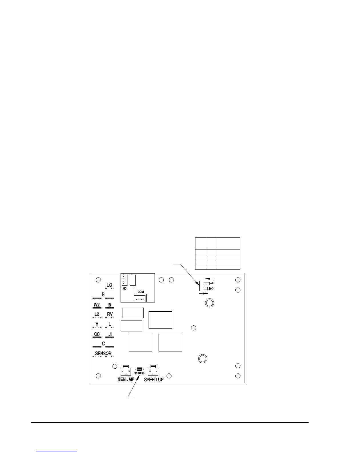
The heat pump defrost control board has an option of 30, 60
or 90-minute setting. By default, this unit is shipped from
the factory with the defrost time on the 60 minute pin. If
circumstances require a change to another time, remove
the wire from the 60-minute terminal and reconnect to the
desired terminal. Refer to Figure 9.
There is a cycle speed up jumper on the control. This can be
used for testing purposes to reduce the time between defrost
cycle operation without waiting for time to elapse.
Use a small screwdriver or other metallic object, or another
¼ inch QC, to short between the SPEEDUP terminals to
accelerate the HPC timer and initiate defrost.
Be careful not to touch any other terminals with the instrument
used to short the SPEEDUP terminals. It may take up to
10 seconds with the SPEEDUP terminals shorted for the
speedup to be completed and the defrost cycle to start.
As soon as the defrost cycle kicks in remove the shorting
instrument from the SPEEDUP terminals. Otherwise the
timing will remain accelerated and run through the 1-minute
minimum defrost length sequence in a matter of seconds and
will automatically terminate the defrost sequence.
FIGure 9
DeFrOst cOntrOl bOarD
LOW PRESSURE BYPASS TIMER SWITCH
*(FACTORY SETTING 120 SECONDS)
SW1SW
OFF
OFF
OFF
ON
ON
OFF
ON
ON
OFF
2 TIME(SEC)
30
60
120*
180
ON
Manual 2100-468J
Page 20 of 29
ACCUMULATED DEFROSTTIMETIMER
(FACTORY SETTING 60 MIN.)
MIS-2668 A
Page 21

There is an initiate defrost jumper (sen jump) on the control
that can be used at any outdoor ambient during the heating
cycle to simulate a 0° coil temperature.
This can be used to check defrost operation of the unit
without waiting for the outdoor ambient to fall into the
defrost region.
By placing a jumper across the SEN JMP terminals (a
¼ inch QC terminal works best) the defrost sensor mounted
on the outdoor coil is shunted out & will activate the timing
circuit. This permits the defrost cycle to be checked out in
warmer weather conditions without the outdoor temperature
having to fall into the defrost region.
In order to terminate the defrost test the SEN JMP jumper
must be removed. If left in place too long, the compressor
could stop due to the high pressure control opening because
of high pressure condition created by operating in the cooling
mode with outdoor fan off. Pressure will rise fairly fast
as there is likely no actual frost on the outdoor coil in this
articial test condition.
There is also a 5-minute compressor time delay function built
into the HPC. This is to protect the compressor from short
cycling conditions. The board’s LED will have a fast blink
rate when in the compressor time delay. In some instances, it
is helpful to the service technician to override or speed up this
timing period, and shorting out the SPEEDUP terminals for a
few seconds can do this.
the low pressure switch input during the rst (30, 60, 120 or
180 seconds) of “Y” operation.
After this period expires, the control will then monitor the low
pressure switch input normally to make sure that the switch is
closed during “Y” operation.
High Pressure Switch Operation - The control has a built-in
lockout system that allows the unit to have the high pressure
switch trip up to two times in one hour and only encounter
a “soft” lockout. A “soft” lockout shuts the compressor off
and waits for the pressure switch to reset, which at that point
then allows the compressor to be restarted as long as the
5-minute short cycle timer has run out. If the high pressure
switch trips a third time within one hour, the unit is in
“hard” lockout indicating something is certainly wrong and
it will not restart itself.
Low Pressure Switch Bypass Operation - The control has a
selectable (SW1) low pressure switch bypass set up to ignore
Manual 2100-468J
Page 21 of 29
Page 22
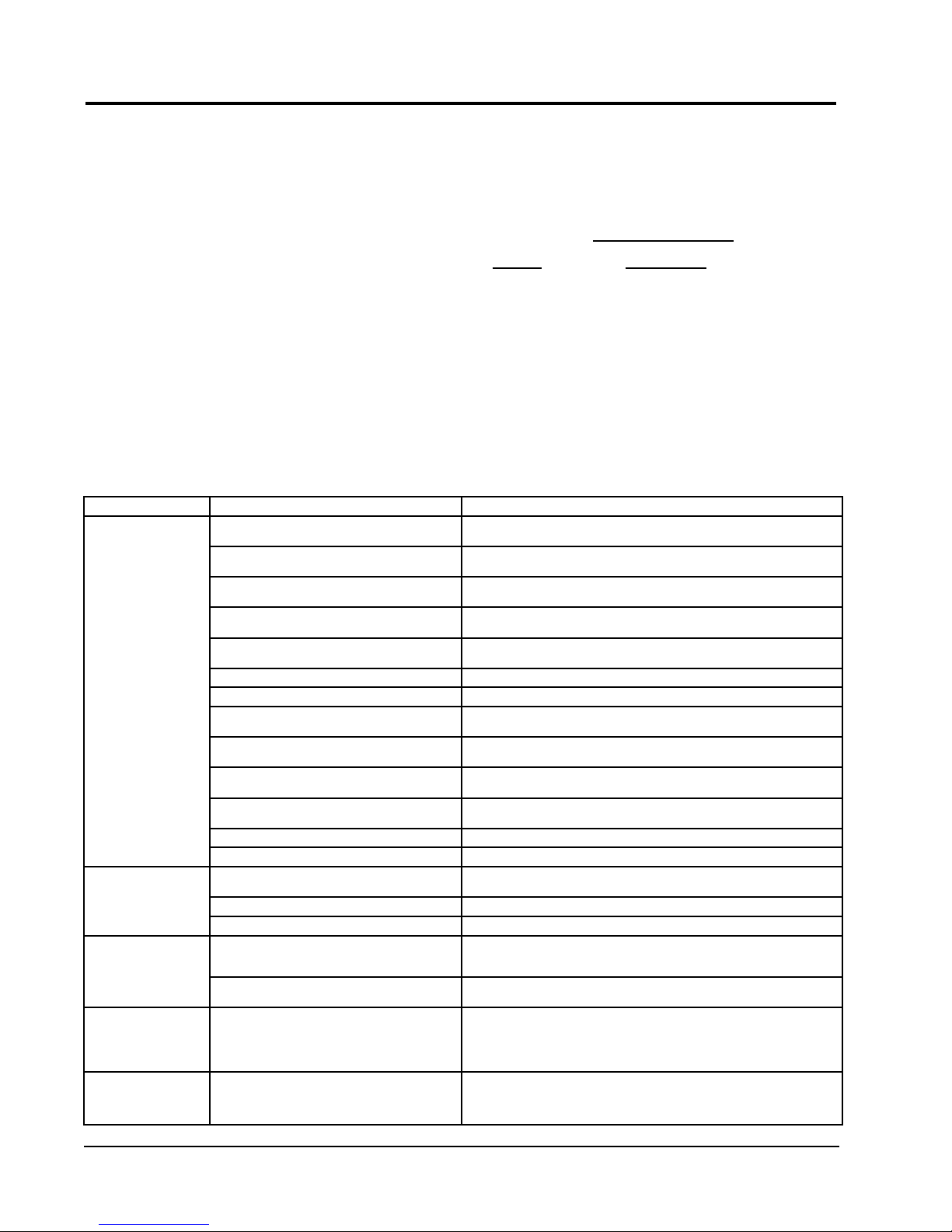
trOubleshOOtInG
sOlID state heat PumP cOntrOl
trOubleshOOtInG PrOceDure
1. NoTE: A thorough understanding of the defrost
cycle sequence is essential. Review that section
NOTE: If there was no power to 24 volt transformer,
the compressor and outdoor fan motor will not
start for 5 minutes. This is because of
the compressor short cycle protection.
earlier in this manual prior to troubleshooting the
control. Turn on AC power supply to unit.
2. Turn thermostat blower switch to “fan on” – the
indoor blower should start. (If it doesn’t,
troubleshoot indoor unit and correct problem.)
3. Turn thermostat blower to “auto” position. Indoor
blower should stop. NoTE: Many models have a
1-minute blower time delay on “off” command;
wait for this to time-out.
4. Set system switch to “heat” or “cool”. Adjust
LED BLINK CoDES
BLINK FUNCTIoN
Slow Normal function (1.0 sec on/1.0 sec off)
Fast
Comp. Delay timer active (0.1 sec on/0.1 sec off)
1 Low pressure switch failure
2 High pressure switch failure/“Soft” Lockout
3 Defrost mode active
4 High pressure switch failure/“Hard” Lockout
thermostat to call for heat or cool. The indoor
blower, compressor and outdoor fan should start.
table 10
trOubleshOOtInG
symptom Description, check & Possible causes What & How to Check / Repair
Compressor will not start
(heating or cooling)
Fan outdoor motor does
not run (cooling or heating
except during defrost)
Reversing valve does not
energize (heating only) Heat pump control defective
Unit will not go into defrost
(heating only)
Unit will not come out of
defrost (heating only)
1. check for leD illumination.
IsthereanLEDilluminatedontheboard(ashing)?
2. check for error codes.
IstheLEDashingaCode?
3. Check for power at board.
Isthere24voltsACbetweenRandC?
4. check codes.
Whatcodeisblinking?
5. compressor delay active.
Wait for 5 minute delay or jump board’s “speed up pins”.
6. Low pressure fault. Check wiring circuit and unit pressures.
7. high pressure fault. Check wiring circuit and unit pressures.
8. check for compressor input signal.
Isthere24voltsACbetweenYandC?
9. No power to board.
10. check for compressor output signal.
Isthere24voltsACbetweenCC&C?
11. no “y” compressor input signal.
12. no “cc” compressor output signal. Checkcompressorcontactorforproperoperationandnallycheckcompressor.
13. Faulty board. Replace defrost board.
Heat pump control defective
Motor defective Check for open or shorted motor winding. Replace motor.
Motor capacitor defective Check capacitor rating. Check for open or shorted capacitor. Replace capacitor.
Reversing valve solenoid coil defective
Temperature sensor or heat pump control defective
Temperature sensor or heat pump control defective
Yes = go to Step #2; No = go to Step #3
Yes = go to Step #4; No = go to Step #8
Yes = go to Step #13; No = go to Step #9
Code “1”, go to Step #6; Code “2”, go to Step#7; Fast Blink, go to Step #5
Check for proper operation; if still needed, go back to Step #1.
Yes = go to Step #10; No = go to Step #11
The unit either does not have unit voltage, the transformer is bad or the unit wiring is
incorrect.
Yes = go to Step #12; No = go to Step #13
Check thermostat wiring, incorrect phase of unit (see section on Phase Monitor), and
nallyunitwiring.
Check across fan relay on heat pump control. (Com-NC)
Replace heat pump control.
Check for 24V between RV-C and B-C.
1. Check control circuit wiring.
2. Replace heat pump control.
Check for open or shorted coil.
Replace solenoid coil.
Disconnect temperature sensor from board and jumper across “SPEEDUP” terminals
and “SEN JMP” terminals. This should cause the unit to go through a defrost cycle within
one minute.
1. If unit goes through defrost cycle, replace temperature sensor.
2. If unit does not go through defrost cycle, replace heat pump control.
Jumper across “SPEEDUP” terminal.
This should cause the unit to come out of defrost within one minute.
1. If unit comes out of defrost cycle, replace temperature sensor.
2. If unit does not come out of defrost cycle, replace heat pump control.
Manual 2100-468J
Page 22 of 29
Page 23
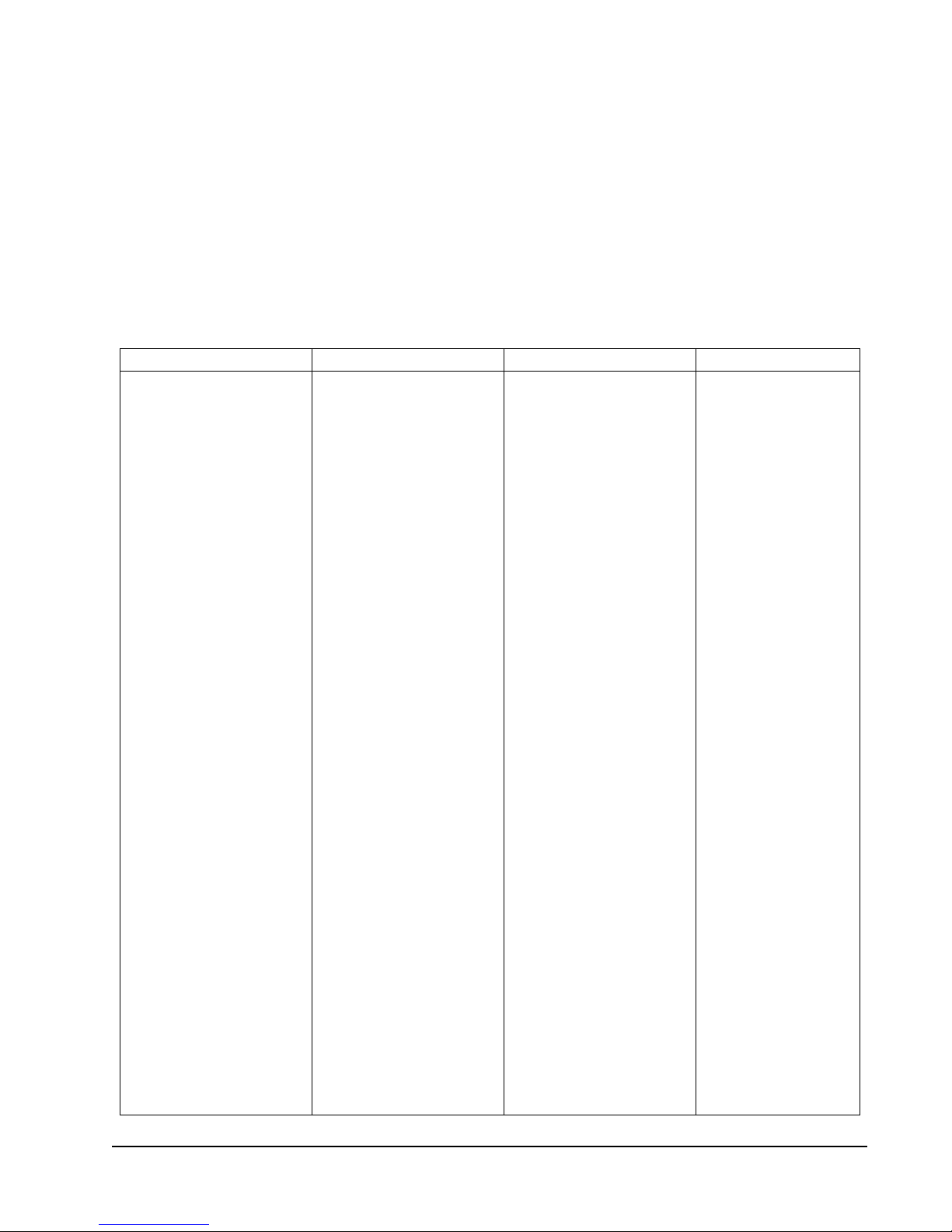
checKInG temPerature sensOr
checK Out
1. Disconnect temperature sensor from board and from
outdoor coil.
2. Use an ohmmeter and measure the resistance of the
sensor. Also use ohmmeter to check for short or open.
3. Check resistance reading to chart of resistance; use
sensor ambient temperature. (Tolerance of part is
± 10%.)
If sensor resistance reads very low, then sensor is
4.
shorted and will not allow proper operation of the heat
pump control.
5. If sensor is out of tolerance, shorted, open, or reads
very low ohms then it should be replaced.
temPerature F Vs resIstance r OF temPerature sensOr
F r F r F r F r
-25.0 196871 13.0 56985 51.0 19374 89.0 7507
-24.0 190099 14.0 55284 52.0 18867 90.0 7334
-23.0 183585 15.0 53640 53.0 18375 91.0 7165
-22.0 177318 16.0 52051 54.0 17989 92.0 7000
-21.0 171289 17.0 50514 55.0 17434 93.0 6840
-20.0 165487 18.0 49028 56.0 16984 94.0 6683
-19.0 159904 19.0 47590 57.0 16547 95.0 6531
-18.0 154529 20.0 46200 58.0 16122 96.0 6383
-17.0 149355 21.0 44855 59.0 15710 97.0 6239
-16.0 144374 22.0 43554 60.0 15310 98.0 6098
-15.0 139576 23.0 42295 61.0 14921 99.0 5961
-14.0 134956 24.0 41077 62.0 14544 100.0 5827
-13.0 130506 25.0 39898 63.0 14177 101.0 5697
-12.0 126219 26.0 38757 64.0 13820 102.0 5570
-11.0 122089 27.0 37652 65.0 13474 103.0 5446
-10.0 118108 28.0 36583 66.0 13137 104.0 5326
-9.0 114272 29.0 35548 67.0 12810 105.0 5208
-8.0 110575 30.0 34545 68.0 12492 106.0 5094
-7.0 107010 31.0 33574 69.0 12183 107.0 4982
-6.0 103574 32.0 32634 70.0 11883 108.0 4873
-5.0 100260 33.0 31723 71.0 11591 109.0 4767
-4.0 97064 34.0 30840 72.0 11307 110.0 4663
-3.0 93981 35.0 29986 73.0 11031 111.0 4562
-2.0 91008 36.0 29157 74.0 10762 112.0 4464
-1.0 88139 37.0 28355 75.0 10501 113.0 4367
0.0 85371 38.0 27577 76.0 10247 114.0 4274
1.0 82699 39.0 26823 77.0 10000 115.0 4182
2.0 80121 40.0 26092 78.0 9760 116.0 4093
3.0 77632 41.0 25383 79.0 9526 117.0 4006
4.0 75230 42.0 24696 80.0 9299 118.0 3921
5.0 72910 43.0 24030 81.0 9077 119.0 3838
6.0 70670 44.0 23384 82.0 8862 120.0 3757
7.0 68507 45.0 22758 83.0 8653 121.0 3678
8.0 66418 46.0 22150 84.0 8449 122.0 3601
9.0 64399 47.0 21561 85.0 8250 123.0 3526
10.0 62449 48.0 20989 86.0 8057 124.0 3452
11.0 60565 49.0 20435 87.0 7869
12.0 58745 50.0 19896 88.0 7686
Manual 2100-468J
Page 23 of 29
Page 24
serVIce
serVIce hInts
1. Caution homeowner to maintain clean air lters at all
times. Also, not to needlessly close off supply and
return air registers. This reduces airow through the
system which shortens equipment service life as well
as increasing operating costs.
2. Switching to heating cycle at 75°F or higher outside
temperature may cause a nuisance trip of the high
pressure switch.
3. The heat pump wall thermostats perform multiple
functions. Be sure that all function switches are
correctly set for the desired operating mode before
trying to diagnose any reported service problems.
Check all power fuses or circuit breakers to be sure
4.
that they are the correct rating.
5. Periodic cleaning of the outdoor coil to permit full and
unrestricted airow circulation is essential.
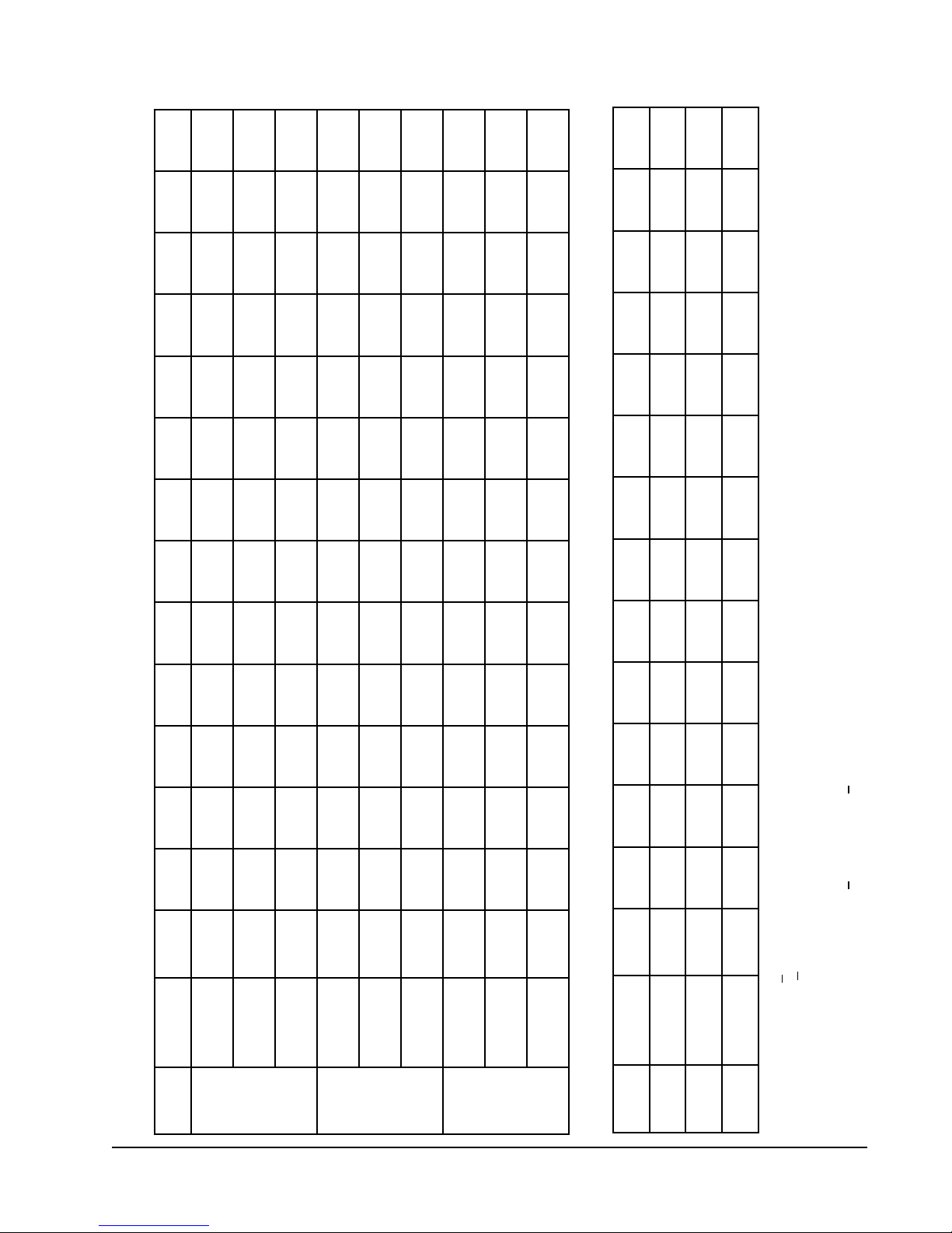
Pressure serVIce POrts
High and low pressure service ports are installed on
all units so that the system operating pressures can be
observed. Pressure tables can be found in Tables 11 &
12 in this manual covering all models on both cooling
and heating cycles. It is imperative to match the correct
pressure table to the unit by model number.
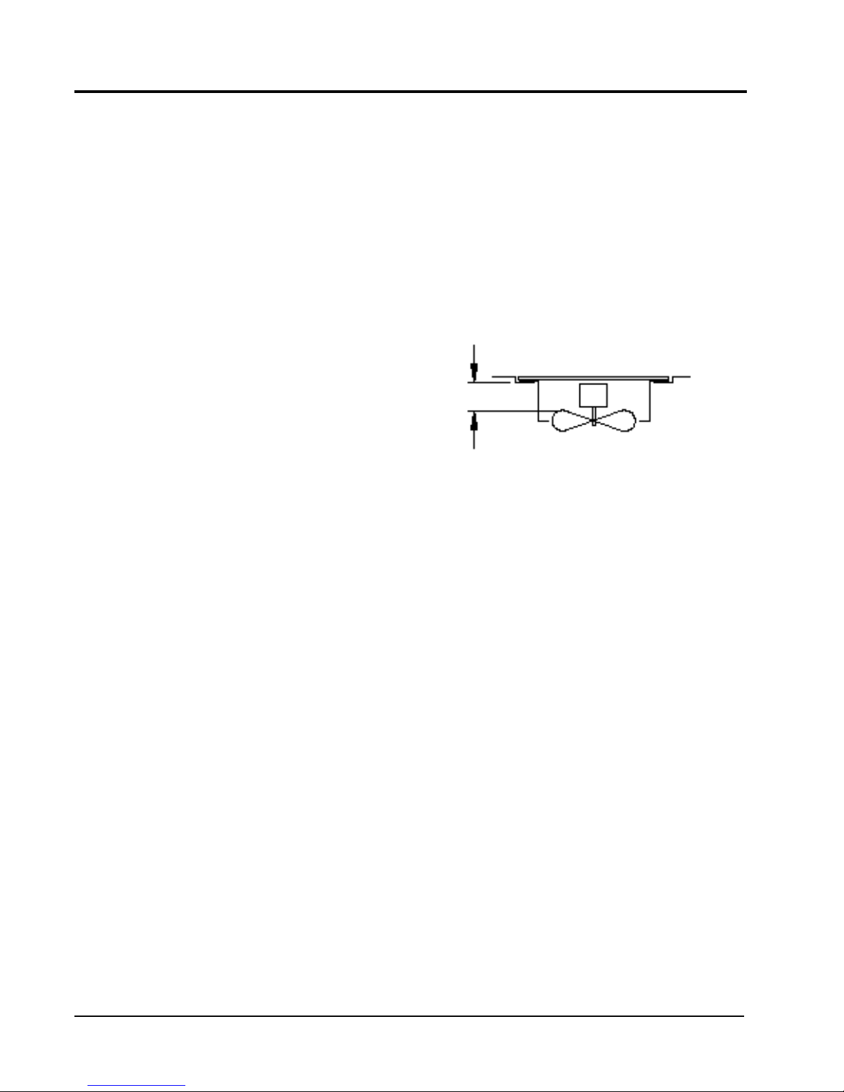
Fan blaDe settInGs
Shown in Figure 10 are the correct fan blade setting
dimensions for proper air delivery across the outdoor coil.
Any service work requiring removal or adjustment in the
fan and/or motor area will require that the dimensions be
checked and blade adjusted in or out on the motor shaft
accordingly.
FIGure 10
Fan blaDe settInG
3¼"
MD-1417BC
r-410a
reFrIGerant charGe
This unit was charged at the factory with the quantity of
refrigerant listed on the serial plate. AHRI capacity and
efciency ratings were determined by testing with this
refrigerant charge quantity.
The following pressure tables show nominal pressures for
the units. Since many installation specic situations can
affect the pressure readings, this information should only
be used by certied technicians as a guide for evaluating
proper system performance. They shall not be used to
adjust charge. If charge is in doubt, reclaim, evacuate and
recharge the unit to the serial plate charge.
Manual 2100-468J
Page 24 of 29
Page 25
143
142
141
140
138
137
136
134
536
511
486
460
435
410
384
361
153
152
151
149
148
146
145
144
163
574
543
512
482
451
421
384
366
161
160
159
157
156
155
153
594
562
530
499
467
435
404
378
151
141
559
150
140
529
149
139
500
148
138
470
Air Temperature Entering Outdoor Coil Degree F
137
136
135
133
440
410
380
357
146
145
144
143
550
524
498
472
446
420
403
370
165
163
162
160
159
157
156
154
569
542
515
489
462
435
408
383
136
136
135
134
133
133
132
130
576
547
518
488
459
429
400
374
146
145
144
143
143
142
139
139
591
561
531
501
470
440
414
384
157
156
155
154
153
152
152
150
612
581
549
518
487
456
424
397
113
325
106
318
311
100
93
304
86
80
73
66
297
290
284
277
Air Temperature Entering Outdoor Coil Degree F
120
113
105
98
91
83
76
69
407
397
386
376
366
355
345
335
119
112
105
98
91
84
77
70
430
420
409
399
389
378
368
358
table 11
Pressure table
132
131
130
128
127
Low Side
Pressure 65° 70° 75° 80° 85° 90° 95° 100° 105° 110° 115° 120° 125°
75° DB
return air
temperature
141
333
140
309
139
285
137
262
136
238
Low Side
High Side
80° DB
62° WB
152
341
151
317
149
293
148
268
146
244
Low Side
High Side
85° DB
67° WB
353
133
338
328
132
315
303
131
292
278
129
269
253
128
246
Low Side
High Side
High Side
75° DB
72° WB
62° WB
142
347
141
323
140
299
138
276
137
252
Low Side
High Side
80° DB
67° WB
153
359
152
334
150
310
149
285
147
261
Low Side
High Side
85° DB
72° WB
129
349
127
324
126
298
124
273
122
248
Low Side
High Side
75° DB
62° WB
138
358
136
332
134
306
133
280
131
254
Low Side
High Side
80° DB
67° WB
148
371
146
344
144
317
143
290
141
263
Low Side
High Side
85° DB
72° WB
60
53
46
40
33
Low Side
Pressure 0° 5° 10° 15° 20° 25° 30° 35° 40° 45° 50° 55° 60°
return air
temperature
61
270
324
54
263
314
47
256
304
39
249
293
32
243
283
Low Side
High Side
High Side
63
347
56
337
49
327
42
316
35
306
Low Side
High Side
model
cOOlInG
PH1324
PH1330
PH1336
model
PH1324 70° DB
PH1330 70° DB
heatInG
PH1336 70° DB
LOW SIDE PRESSURE +4 PSIG
HIGH SIDE PRESSURE +10 PSIG
TablesbaseduponratedCFM(airow)acrosstheevaporatorcoil.
If incorrect charge suspected (more than +4 psig suction, +10psigliquid),
itisrecommendedrefrigerantchargebereclaimed,systemevacuatedandchargedtoserialplatequantity.
Manual 2100-468J
Page 25 of 29
Page 26
138
137
137
136
136
135
135
133
560
530
501
471
441
411
381
358
148
147
146
146
145
145
144
143
160
566
537
508
478
449
419
402
366
159
158
158
157
157
156
154
586
556
525
495
465
434
404
379
149
139
552
148
138
524
147
138
495
147
137
466
Air Temperature Entering Outdoor Coil Degree F
137
136
136
134
438
409
380
357
146
146
145
144
575
544
513
483
452
422
418
368
159
158
157
157
156
155
155
153
595
563
531
500
468
436
405
381
133
132
131
129
128
127
126
530
501
472
442
413
383
360
142
141
140
138
137
137
135
544
514
484
453
430
423
369
153
151
150
149
147
146
145
563
532
501
469
438
407
382
119
111
104
97
90
83
76
68
375
366
357
348
339
330
322
313
115
107
100
93
86
79
72
64
345
337
330
322
314
307
299
291
121
390
113
380
106
371
99
362
92
85
77.5
70
353
344
335
325
Air Temperature Entering Outdoor Coil Degree F
table 12
Pressure table
133
132
131
129
128
Low Side
Pressure 65° 70° 75° 80° 85° 90° 95° 100° 105° 110° 115° 120° 125°
75° DB
return air
temperature
142
333
141
310
140
287
138
263
137
240
Low Side
High Side
80° DB
62° WB
153
342
152
318
150
294
149
270
147
246
Low Side
High Side
85° DB
67° WB
354
132
329
131
304
130
279
128
255
127
Low Side
High Side
75° DB
72° WB
141
336
140
313
139
290
137
267
136
245
Low Side
High Side
80° DB
62° WB
152
356
344
151
332
321
149
308
298
148
284
274
146
260
251
Low Side
High Side
High Side
85° DB
72° WB
67° WB
125
337
124
314
123
291
122
268
122
245
Low Side
High Side
75° DB
62° WB
134
346
133
322
132
298
131
275
130
251
Low Side
High Side
80° DB
67° WB
144
358
143
333
142
309
141
284
140
260
Low Side
High Side
85° DB
72° WB
63
56
49
42
34.5
Low Side
Pressure 0° 5° 10° 15° 20° 25° 30° 35° 40° 45° 50° 55° 60°
return air
temperature
61
316
304
54
307
295
47
298
286
40
289
277
33
280
269
Low Side
High Side
High Side
57
284
50
276
43
268
36
261
29
253
Low Side
High Side
model
cOOlInG
PH1342
Manual 2100-468J
Page 26 of 29
PH1348
PH1360
model
PH1342 70° DB
PH1348 70° DB
heatInG
PH1360 70° DB
LOW SIDE PRESSURE +4 PSIG
HIGH SIDE PRESSURE +10 PSIG
TablesbaseduponratedCFM(airow)acrosstheevaporatorcoil.
If incorrect charge suspected (more than +4 psig suction, +10psigliquid),
itisrecommendedrefrigerantchargebereclaimed,systemevacuatedandchargedtoserialplatequantity.
Page 27
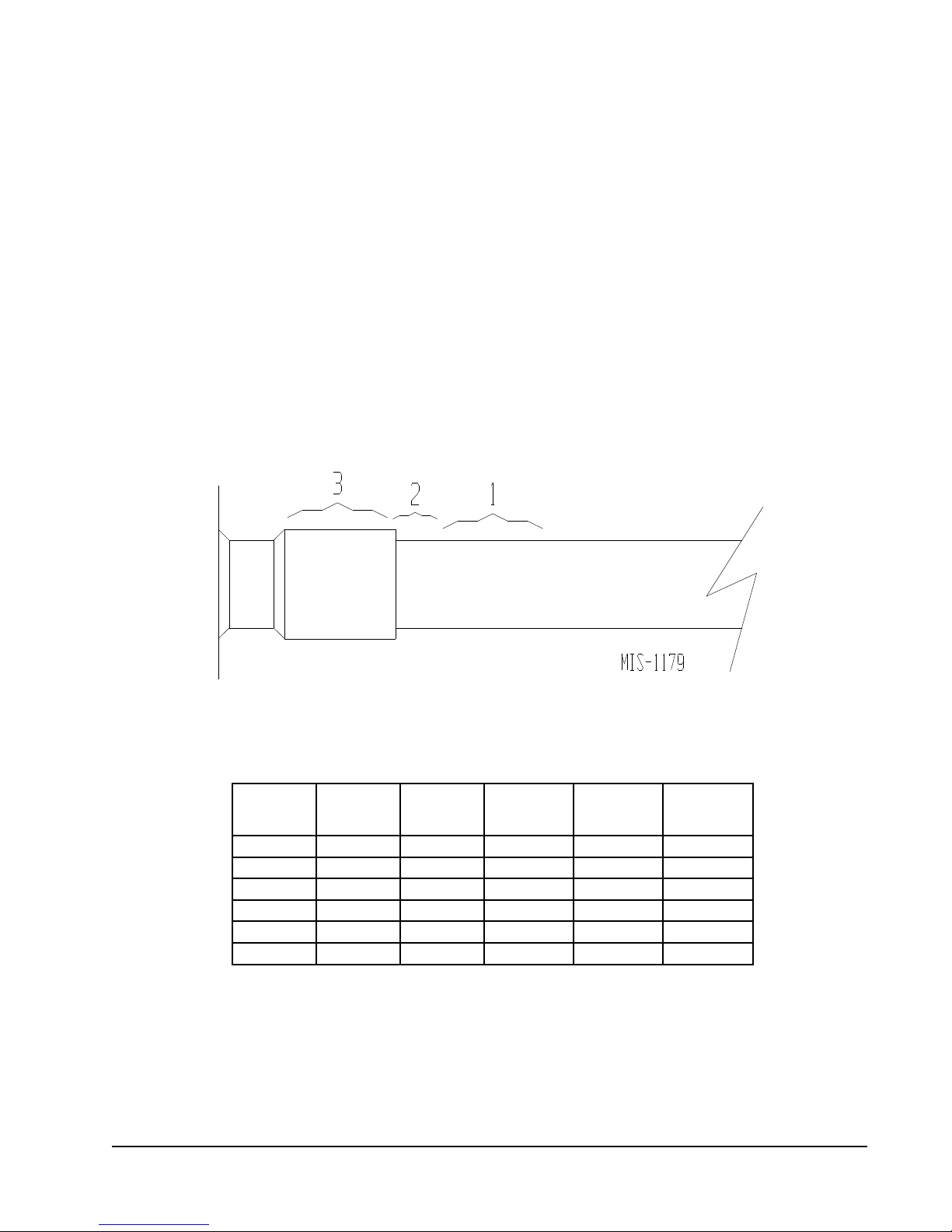
suctIOn anD DIscharGe tube
brazInG
Compliant Scroll compressors have copper plated steel
suction and discharge tubes. These tubes are far more
rugged and less prone to leaks than copper tubes used on
other compressors. Due to different thermal properties
of steel and copper, brazing procedures may have to be
changed from those commonly used.
• To disconnect: heat joint Areas 2 and 3 slowly and
uniformly until braze material softens and the tube can
be pulled out of suction tting. (See Figure 11.)
• To connect:
– Recommended brazing materials: silfos with
minimum 5% silver or silver braze material with
ux.
brazInG DIaGram
– Reinsert tube into tting.
– Heat tube uniformly in Area 1 moving slowly to
Area 2. When joint reaches brazing temperature,
apply brazing material. (See Figure 11.)
– Heat joint uniformly around the circumference to
ow braze material completely around the joint.
– Slowly move torch into Area 3 to draw braze
material into joint. (See Figure 11.)
– Do not overheat joint.
FIGure 11
table 13
InDOOr blOwer PerFOrmance
model
PH1324 0.10 0.50 600 800 800
PH1330 0.15 0.50 750 1000 1000
PH1336 0.15 0.50 825 1100 1100
PH1342 0.20 0.50 925 1400 1400
PH1348 0.20 0.50 1025 1550 1550
PH1360 0.20 0.50 1150 1750 1750
Motor will deliver consistent CFM through voltage supply range with no deterioration
(197-253V for all 230/208V models).
Continuous CFM is the total air being circulated during continuous (manual fan) mode.
Will occur automatically with a call for "Y" for cooling mode operation.
Will occur automatically with a call for "W1" for heating mode operation.
rated
esP
max
esP
continuous
Airow
rated
cooling cFm
rated
heating cFm
Manual 2100-468J
Page 27 of 29
Page 28
trOubleshOOtInG Ge x13-serIes ecm2.3™ mOtOrs
FIGURE 10
NOTE: Bard Models PA13242; PA13302; PA13362-A, -B; PA13422-A, -B, -C; PA13482-A, -B, -C; PA13602-A, -B, -C
contain the X13-Series Motors.
TROUBLESHOOTING GE X13-SERIES ECM2.3™ MOTORS
If the Motor is Running
1. It is normal for the motor to rock back and forth on start up.
Do not replace the motor if this is the only problem identified.
2. If the system is excessively noisy, does not appear to change
speeds in response to a demand (Heat, Cool, Other), or is having
symptoms during the cycle such as tripping limit or freezing coil,
check the following:
a. Wait for programmed delays to time out.
b.Ensure that the motors control inputs are wired to the factory
supplied wiring diagram to insure motor is getting proper
control signals and sequencing.
c. Remove the filter and check that all dampers, registers, and
grilles are open and free flowing. If removing the filters
corrects the problem, clean or replace with a less restrictive
filter. Also check and clean the blower wheel or coil as
necessary.
d.Check the external static pressure (total of both supply and
return) to insure that you are within the ranges as listed on the
unit serial plate. If higher than allowed, additional duct work
is needed.
e. If the motor does not shut off at the end of the cycle, wait for
any programmed delays to time out (no more than 90
seconds). Also make sure that there is no call for
“Continuous Fan” on the "G" terminal.
f. If the above diagnostics do not solve the problem, confirm the
voltage checks in the next section below, then continue with
the “Model X13 Communication Diagnostics”.
If the Motor is Not Running
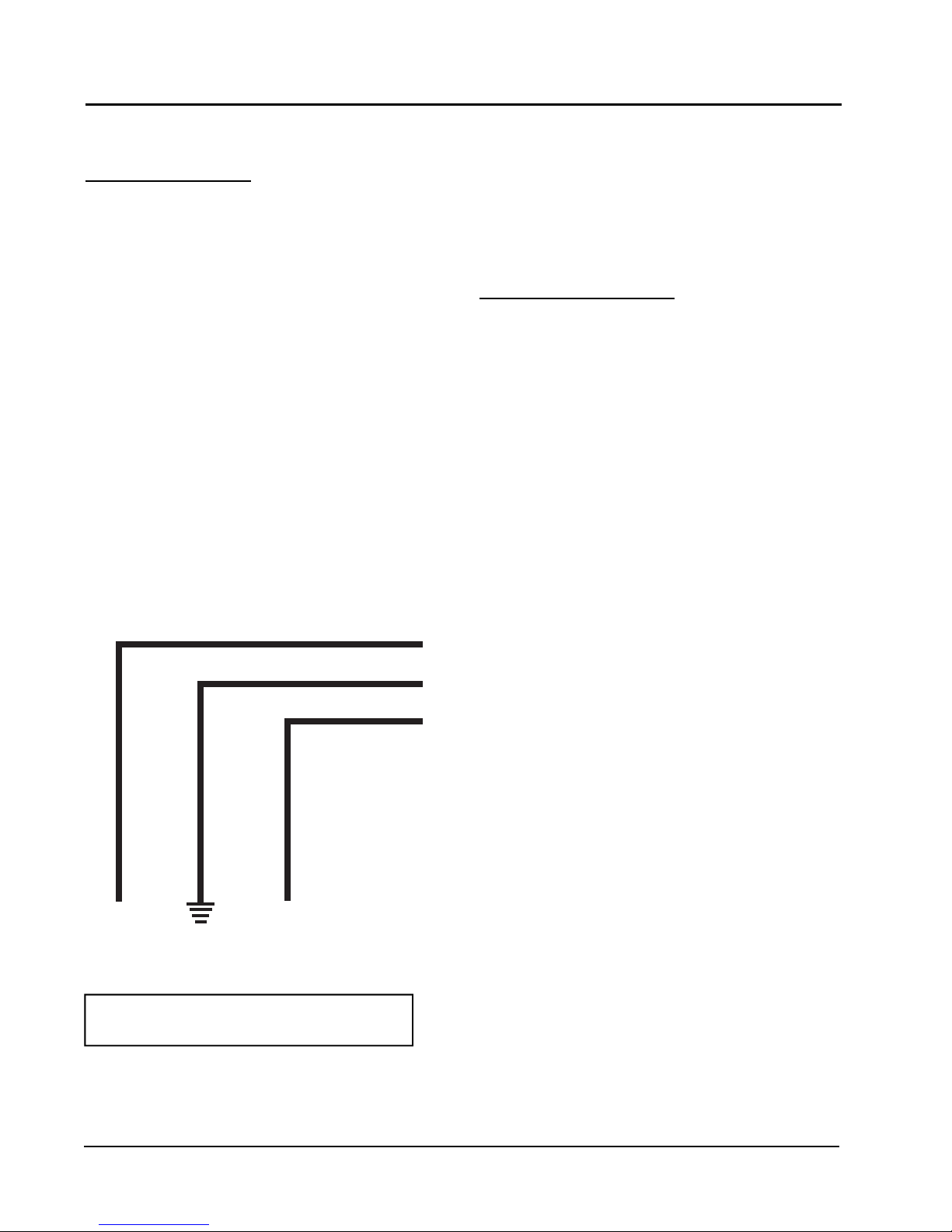
1. Check for proper high voltage and ground at the (L/L1) (G) (N/
L2) connections at the motor (see Figure 10). Correct any voltage
issues before proceeding to the next step. The X13 Motor is voltage
specific. Only the correct voltage should be applied to the proper
motor. Input voltage within plus or minus 10% of the nominal 230
VAC is acceptable.
2. If the motor has proper high voltage and ground at the (L/L1)
(G) (N/L2) connections, then continue with the “Model X13
Communication Diagnostics”.
NOTE:
contain the X13-Series Motors.
Bard Models PH13242; PH13302; PH13363-A, -B; PH13422-A, -B, -C; PH13482-A, -B, -C; PH13602-A, -B, -C
If the Motor is Running
1. It is normal for the motor to rock back and forth on start up. Do
not replace the motor if this is the only problem identied.
2. If the system is excessively noisy, does not appear to change
speeds in response to a demand (Heat, Cool, Other), or is having
symptoms during the cycle such as tripping limit or freezing coil, check
the following:
a. Wait for programmed delays to time out.
b. Ensure that the motors control inputs are wired to the factory
supplied wiring diagram to insure motor is getting proper
control signals and sequencing.
c. Remove the lter and check that all dampers, registers, and
grilles are open and free owing. If removing the lters
corrects the problem, clean or replace with a less restrictive
lter. Also check and clean the blower wheel or coil as
necessary.
d. Check the external static pressure (total of both supply and
return) to insure that you are within the ranges as listed on the
unit serial plate. If higher than allowed, additional duct work
is needed.
FIGure 12
e. If the motor does not shut off at the end of the cycle, wait for
any programmed delays to time out (no more than 90
seconds). Also make sure that there is no call for
“Continuous Fan” on the "G" terminal.
f. If the above diagnostics do not solve the problem, conrm the
voltage checks in the next section below, then continue with
the “Model X13 Communication Diagnostics”.
If the Motor is Not Running
1. Check for proper high voltage and ground at the (L/L1) (G) (N/
L2) connections at the motor (see Figure 12). Correct any voltage
issues before proceeding to the next step. The X13 Motor is voltage
specic. Only the correct voltage should be applied to the proper
motor. Input voltage within plus or minus 10% of the nominal 230
VAC is acceptable.
2. If the motor has proper high voltage and ground at the (L/
L1) (G) (N/L2) connections, then continue with the “Model X13
Communication Diagnostics”.
↓
L2 LINE
POWER
EARTH
GROUND
↓
L1 LINE
POWER
NOTE: MOTOR IS CONS TA NTLY
POWERED BY LINE VOLTAGE
Manual 2100-468J
Page 28 of 29
Page 29
trOubleshOOtInG Ge x13-serIes ecm2.3™ mOtOrs cOnt’D.
FIGURE 11
™
MOTORS
CONT’D.
2. Initiate a demand from the thermostat and check the
voltage between the common and the appropriate motor
terminal (1-5). ("G" input is typically on terminal #1, but
refer to wiring diagram!)
a. If the low voltage communication is not present, check
the demand from the thermostat. Also check the
output terminal and wire(s) from the terminal strip or
control relay(s) to the motor.
b. If the motor has proper high voltage as identified
above (Motor not Running #1), and proper low voltage
to a programmed terminal, and is not operating, the
motor is failed, and will require replacement.
Model X13 Communication Diagnostics
The X13 motor is communicated through 24 VAC low voltage
(Thermostat Control Circuit Wiring).
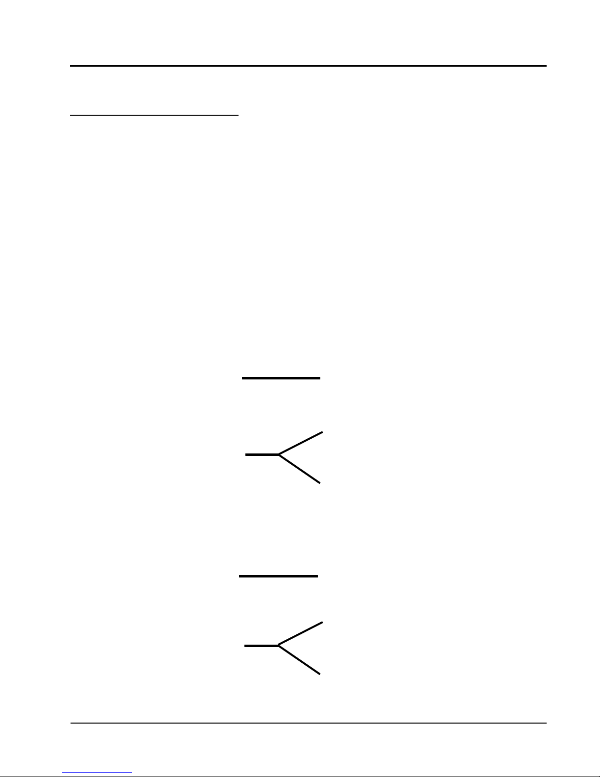
1. Start with unit wiring diagram to conrm proper
connections and voltage (see Figure 13).
FIGure 13
24VAC Common
2. Initiate a demand from the thermostat and check the
voltage between the common and the appropriate motor
terminal (1-5). ("G" input is typically on terminal #1, but
refer to wiring diagram!)
a. If the low voltage communication is not present, check
the demand from the thermostat. Also check the
output terminal and wire(s) from the terminal strip or
control relay(s) to the motor.
b. If the motor has proper high voltage as identied
above (Motor not Running #1), and proper low voltage
to a programmed terminal, and is not operating, the
motor is failed, and will require replacement.
24VAC "R" Signal thro ugh
thermostat output.
24VAC Common
24VAC "R" Signal thro ugh
thermostat output.
Manual 2100-468J
Page 29 of 29
 Loading...