

Page 1

INSTALLATION INSTRUCTIONS
SINGLE PACKAGE
HEAT PUMPS
Models:
PH11242 PH12241
PH11301 PH1230
PH11361 PH1236
PH11422 PH1242
PH10481 PH12481
PH1060
Bard Manufacturing Company, Inc.
Bryan, Ohio 43506
Since 1914 . . . Moving ahead, just as planned.
Manual : 2100-354F
Supersedes: 2100-354E
File: Volume II Tab 11
Date: 12-20-06
© Copyright 2004
Manual 2100-354F
Page 1 of 32
Page 2

CONTENTS
Getting Other Informations and Publications
General Instructions
Important ................................................................ 3
Shipping Damage .................................................... 4
General ................................................................ 4
Field-Installed Heater Packages (Optional) ............. 4
Installation
Location ............................................................... 11
Typical Installations ....................................... 11 & 16
Condensate Drain Trap ......................................... 16
Air Filters .............................................................. 16
Wiring – Main Power ............................................. 17
Wiring – 24V Low Voltage Control Circuit ............. 17
Thermostats ........................................................... 18
Thermostat Indicator Lamps .................................. 19
Emergency Heat Position ...................................... 19
Transformer Taps ................................................... 19
Compressor Cutoff Thermostat and Outdoor
Thermostat Wiring ................................................. 19
Figures
Figure 1 Unit Dimensional Drawing ..................... 10
Figure 2 Slab Mounting at Ground Level ............ 12
Figure 3 Airflow and Service Access
Clearances ............................................ 12
Figure 4 Roof Top Application ............................. 13
Figure 5 Elevated Mounting Platforms ................ 13
Figure 6 Prefabricated Rood Curb
Specifications ........................................ 14
Figure 7 Field Fabricated Curbing ....................... 15
Figure 8 Condensate Drain Trap ......................... 16
Figure 9 Low Voltage Wiring ............................... 17
Figure 10 Unit 24V Terminal Board (5–10 KW)..... 19
Figure 11 Unit 24V Terminal Board (15–20 KW) ... 20
Figure 12 Heat Pump Control Board ..................... 22
Figure 13 Fan Blade Setting ................................. 25
Figure 14 Brazing Diagram ................................... 26
Start Up and Operation
Three Phase Scroll Compressor Start Up
Information ............................................................. 21
Sequence of Operation .......................................... 21
Defrost Cycle ......................................................... 22
Troubleshooting
Solid State Heat Pump Control
Troubleshooting Procedure ................................... 23
Troubleshooting Guide .......................................... 23
Checking Temperature Sensor Check Out ............ 24
Temperature vs. Resistance of
Temperature Sensor Chart .................................... 24
Service
Service Hints ......................................................... 25
Pressure Service Ports .......................................... 25
Refrigerant Charge ................................................ 25
Fan Blade Settings ................................................ 25
Suction and Discharge Tube Brazing .................... 26
Troubleshooting GE ECM™ Blower Motors ... 27 & 28
Pressure Tables ................................................ 29-32
Tables
Table 1 Rated CFM and ESP .............................. 4
Table 2 Electrical Data ......................................... 5
Table 2A Electrical Data ......................................... 6
Table 2B Electrical Data ......................................... 7
Table 3 Optional Field Installed Heater
Packages ................................................ 8
Table 4 Electric Heater Table ............................... 9
Table 5 Dimensions of Unit................................ 10
Table 6 Roof Curb Dimensions .......................... 14
Table 7 Dimension “X” for Field Fab Curbing .... 15
Table 8 Filters Required & Size ......................... 16
Table 9 Heat Pump Thermostats ....................... 18
Table 10 Thermostat Wire Size ........................... 18
Table 11 Compressor Cutoff Thermostat
Wiring (5 - 10 KW) ............................... 20
Table 12 Compressor Cutoff Thermostat
Wiring (15 - 20 KW) ............................. 20
Table 13 Refrigerant Charge ............................... 25
Table 14 Fan Blade Setting Dimensions .............. 25
Table 15 Indoor Blower Performance .................. 26
Table 16 Pressure Table - Cooling ....................... 29
Table 17 Pressure Table - Heating ...................... 29
Table 18 Pressure Table - Cooling ....................... 30
Table 19 Pressure Table - Heating ...................... 30
Table 20 Pressure Table - Cooling ....................... 31
Table 21 Pressure Table - Heating ...................... 31
Table 22 Pressure Table - Cooling ....................... 32
Table 23 Pressure Table - Heating ...................... 32
Manual 2100-354F
Page 2 of 32
Page 3

Getting Other Information and Publications
These publications can help you install the air conditioner
or heat pump. You can usually find these at your local
library or purchase them directly from the publisher. Be
sure to consult current edition of each standard.
National Electrical Code ........................... ANSI/NFPA 70
Standard for the Installation ................... ANSI/NFPA 90A
of Air Conditioning and Ventilating Systems
Standard for Warm Air .......................... ANSI/NFPA 90B
Heating and Air Conditioning Systems
Load Calculation for ................................ ACCA Manual J
Residential Winter and Summer Air Conditioning
Duct Design for Residential ................... ACCA Manual D
Winter and Summer Air Conditioning and Equipment
Selection
FOR MORE INFORMATION, CONTACT
THESE PUBLISHERS:
ACCA Air Conditioning Contractors of America
1712 New Hampshire Ave. N.W.
Washington, DC 20009
Telephone: (202) 483-9370
Fax: (202) 234-4721
ANSI American National Standards Institute
11 West Street, 13th Floor
New York, NY 10036
Telephone: (212) 642-4900
Fax: (212) 302-1286
ASHRAE American Society of Heating Refrigerating,
and Air Conditioning Engineers, Inc.
1791 Tullie Circle, N.E.
Atlanta, GA 30329-2305
Telephone: (404) 636-8400
Fax: (404) 321-5478
NFPA National Fire Protection Association
Batterymarch Park
P.O. Box 9101
Quincy, MA 02269-9901
Telephone: (800) 344-3555
Fax: (617) 984-7057
Manual 2100-354F
Page 3 of 32
Page 4
GENERAL INSTRUCTIONS
IMPORTANT
The equipment covered in this manual is to be installed by
trained, experienced service and installation technicians.
Any heat pump is more critical of proper operating charge
and an adequate duct system than a straight air conditioning
unit. All duct work, supply and return ducts, must be
properly sized for the design air flow requirement of the
equipment. ACCA is an excellent guide to proper sizing.
All duct work or portions thereof not in the conditioned
space should be properly insulated in order to both
conserve energy and prevent condensation or moisture
damage.
SHIPPING DAMAGE
Upon receipt of equipment, the carton should be checked
for external signs of shipping damage. If damage is found,
the receiving party must contact the last carrier
immediately, preferably in writing, requesting inspection
by the carrier’s agent.
GENERAL
The refrigerant system is completely assembled and
charged. All internal wiring is complete.
The unit is designed for use with or without duct work.
Flanges are provided for attaching the supply and return
ducts.
These instructions and any instructions packaged with any
separate equipment required to make up the entire heat
pump system should be carefully read before beginning the
installation. Note particularly “Starting Procedure” and any
tags and/or labels attached to the equipment.
While these instructions are intended as a general
recommended guide, they do not supersede any national
and/or local codes in any way. Authorities having
jurisdiction should be consulted before the installation is
made.
FIELD INSTALLED HEATER PACKAGES
(OPTIONAL)
These packaged heat pumps are manufactured without
supplementary electric heaters. Supplementary heaters are
available for simple, fast field installation.
A separate power circuit is required for the supplementary
heaters.
IMPORTANT: Refer to Table 1 when designing duct work
for maximum available static pressure with heater installed.
Refer to electrical data shown in Tables 3 and 4 for proper
application information on all available heater
combinations and what units they can be used with. It also
shows the applicable circuit ampacities, fuse size, and wire
size for each heater combination.
These instructions explain the recommended method to
install the air cooled self-contained unit and the electrical
wiring connections to the unit.
RATED CFM AND EXTERNAL STATIC PRESSURE (ESP)
ledoM
24211HP008088-08602.005.0
14221HP008
10311HP00010011-57703.004.0
0321HP0001
16311HP00010121-57702.004.0
6321HP0001
22411HP00410451-062102.053.0
2421HP0041
18401HP05510071-004104.005.0
18421HP0551
0601HP00710781-035102.005.0
detaR
MFC
NOTE: Motor will adjust to deliver rated airflow.
TABLE 1
1etoN
1etoN
1etoN
1etoN
1etoN
dednemmoceR
egnaRwolfriA
detaR
PSE
01.005.0
51.005.0
51.005.0
51.005.0
02.005.0
mumixaM
PSE
Manual 2100-354F
Page 4 of 32
Page 5
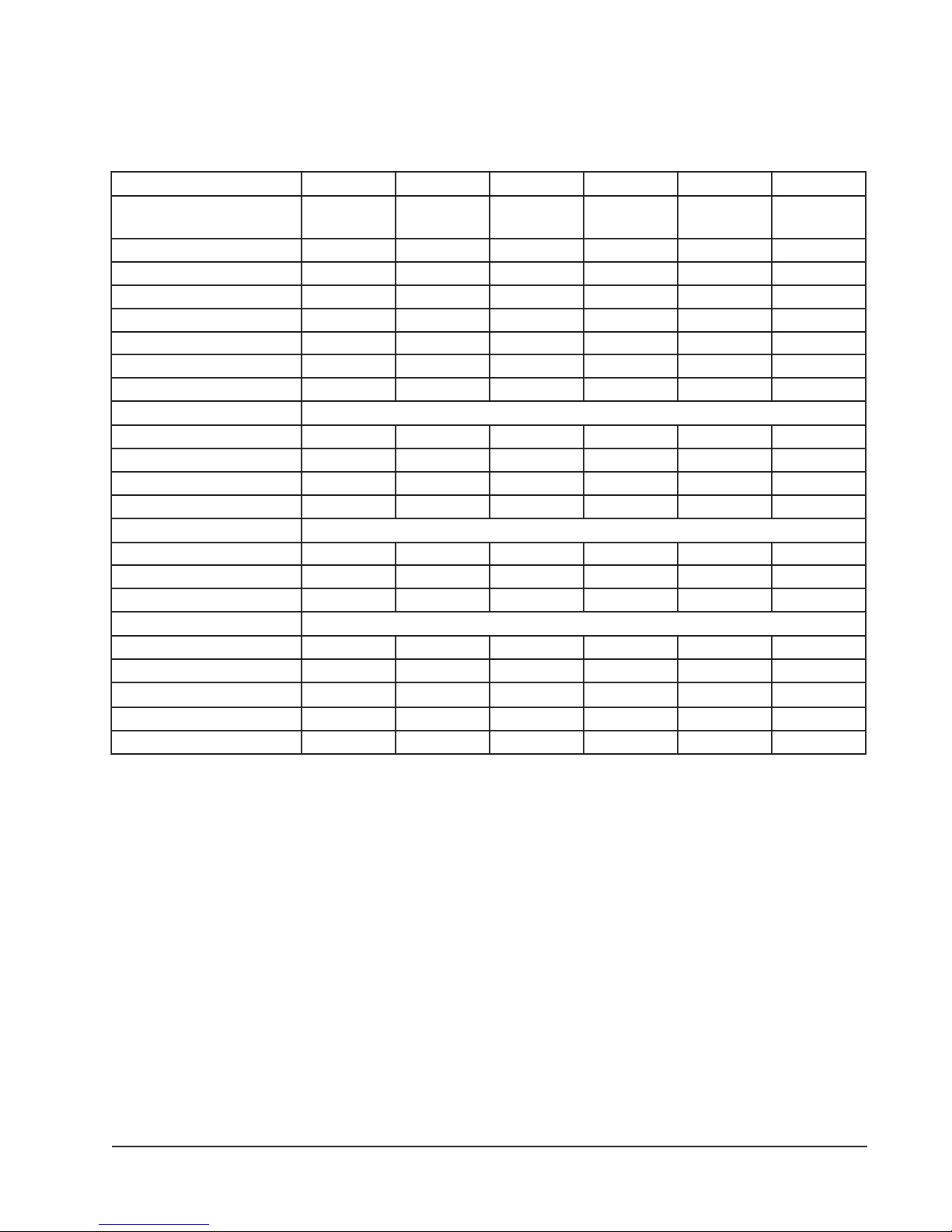
TABLE 2
ELECTRICAL DATA
ledoM24211HP10311HP16311HPB-16311HPC-16311HP22411HP
gnitaRcirtcelE
AtkC-zH06
1-06-802/0321-06-802/0321-06-802/0323-06-802/0323-06-0641-06-802/032
egnaRegatoVgnitarepO352-791352-791352-791352-781605-414352-791
yticapmAtiucriCmuminiM711252812123
CSCB115.3181116
*eziSeriWdleiF0101801418
eziSeriWdnuorG010101014101
**.xaM-esuFyaleD520304525105
802-302-spmAtinUlatoT9.41/9.312.71/7.517.02/9.818.31/2.319.62.42/8.22
AtiucriC-rosserpmoC
epyTrosserpmoCllorcSllorcSllorcSllorcSllorcSllorcS
stloV802/032802/032802/032802/032064802/032
spmAdaoLdetaR11/0131/5.115.61/7.416.9/0.97.45.81/1.71
spmArotoRkcoL45/455.27/5.2788/8877/7793401/401
resnednoCdnarotoMnaF
MPR/PH-rotoMnaF0901-5/15701-5/15701-5/15701-5/15701-5/1528-3/1
spmArotoMnaF2.16.16.16.18.05.2
MFC/aiDnaF0561/"020002/"020002/"020002/"020002/"020592/"42
rotaropavEdnarotoM
MPR/PH-rotoMrewolB5701-3/15701-3/15701-3/15701-3/15701-3/15701-2/1
spmA-rotoMrewolB1.26.26.26.24.17.3
PSE&gnilooCMFC02.0@00803.0@001102.0@001102.0@001102.0@001102.0@0041
).zo22-R(egrahC8839686868121
)sdnuop(thgieWgnippihS563563563563563534
5.81
* 75 degree C copper wire
** Maximum time delay fuse of HACR type circuit breaker
Manual 2100-354F
Page 5 of 32
Page 6
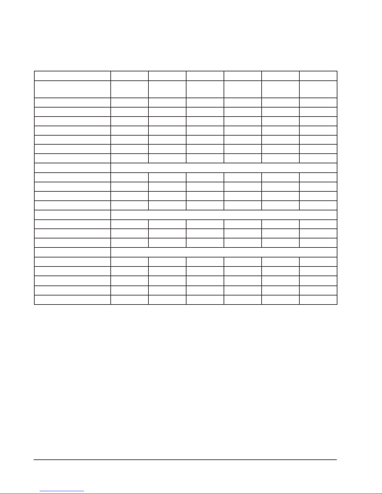
TABLE 2A
ELECTRICAL DATA
ledoM18401HPB-18401HPC-18401HP0601HPB-0601HPC-0601HP
gnitaRcirtcelE
AtkC-zH06
1-06-802/0323-06-802/0323-06-0641-06-802/0323-06-802/0323-06-064
egnaRegatoVgnitarepO352-791352-781605-414352-791352-781605-414
yticapmAtiucriCmuminiM435221349241
CSCB5.127.411.792819
*eziSeriWdleiF8
8218821
eziSeriWdnuorG010101010121
**.xaM-esuFyaleD055351065402
802-302-spmAtinUlatoT2.12/2.527.91/3.819
5.23/3.038.22/3.1211
AtiucriC-rosserpmoC
epyTrosserpmoCllorcSllorcSllorcSllorcSllorcSllorcS
stloV802/032802/032064802/032802/032064
spmAdaoLdetaR5.12/5.910.41/6.212.68.62/6.421.71/6.512.8
spmArotoRkcoL731/73119/1905841/841731/73126
resnednoCdnarotoMnaF
MPR/PH-rotoMnaF058-3/1058-3/1058-3/1058-3/1058-3/1058-3/1
spmArotoMnaF5.25.22.15.25.22.1
MFC/aiDnaF0003/"420003/"420003/"420003/"420003/"420003/"42
rotaropavEdnarotoM
MPR/PH-rotoMrewolB5701-2/15701-2/15701-2/15701-2/15701-2/15701-2/1
spmA-rotoMrewolB7.37.38.17.37.38.1
PSE&gnilooCMFC0551
@
04.00551
@
04.00551
@
04.00071
@
02.00071
@
02.00071
@
02.0
).zo22-R(egrahC521521521761761761
)sdnuop(thgieWgnippihS054054054054054054
* 75 degree C copper wire
** Maximum time delay fuse of HACR type circuit breaker
Manual 2100-354F
Page 6 of 32
Page 7
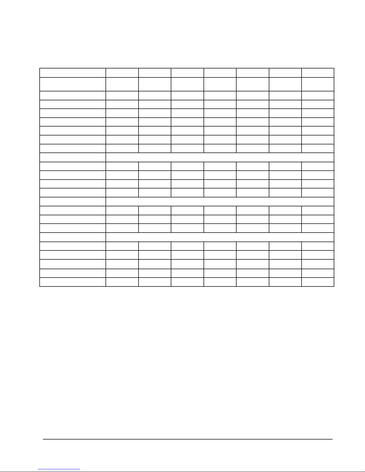
TABLE 2B
ELECTRICAL DATA
ledoM14221HP0321HP6321HPB-6321HP2421HP18421HPB-18421HP
gnitaRcirtcelE
AtkC-zH06
egnaRegatoVgnitarepO352-791352-791352-791352-781352-791352-791352-781
yticapmAtiucriCmuminiM7112629103334.52
CSCB5.015.315.619.01815.027.41
*eziSeriWdleiF21010121018
eziSeriWdnuorG01010101010101
**.xaM-esuFyaleD52030452540553
802-302-spmAtinUlatoT9.31/9.211.71/6.512.12/4.916.51/7.415.42/5.325.72/5.523.02/0.91
AtiucriC-rosserpmoC
epyTrosserpmoCllorcSllorcSllorcSllorcSllorcSllorcSllorcS
stloV802/032802/032802/032802/032802/032802/032802/032
spmAdaoLdetaR5.01/5.90.31/5.115.61/7.419.01/017.71/7.615.02/5.813.31/0.21
spmArotoRkcoL45/455.27/5.2788/8877/77401/401731/73119/19
resnednoCdnarotoMnaF
MPR/PH-rotoMnaF0901-5/15701-5/15701-5/15701-5/1528-3/1528-3/1528-3/1
spmArotoMnaF2.14.14.14.15.25.25.2
MFC/aiDnaF0561/"020002/"020002/"020002/"020003/"420003/"420003/"42
rotaropavEdnarotoM
MPR/PH-rotoMrewolBelbairaV3/1elbairaV2/1elbairaV2/1elbairaV2/1elbairaV4/3elbairaV4/3elbairaV4/3
spmA-rotoMrewolB1.27.23.33.33.45.45.4
PSE&gnilooCMFC01.0@00851.0@000151.0@000151.0@000102.0@004102.0@055102.0@0551
).zo22-R(egrahC1999121121331321321
)sdnuop(thgieWgnippihS023533543543024044044
1-06-802/0321-06-802/0321-06-802/0323-06-802/0321-06-802/0321-06-802/0323-06-802/032
8
* 75 degree C copper wire
** Maximum time delay fuse of HACR type circuit breaker
Manual 2100-354F
Page 7 of 32
Page 8
tfelneebsah
nmulocsihT
yllanoitnetni
knalb
TABLE 3
AN SAA ANAN
AN ASA ANS3
OPTIONAL FIELD INSTALLED HEATER PACKAGES
ANSAN SAA ANAN
ONLY TO BE USED WITH THE HEAT PUMP MODELS INDICATED
dnastloV
esahP24211HP14221HP10311HP0321HP16311HPB-16311HPC-16311HP6321HPB-6321HP
50A-CP3HE1-802/042ANSANSANANANSAN
01A-CP3HE1-802/042ANSANANANANANANAN
80A-BP3HE1-802/042SANSAN SAA ANAN
50A-BP3HE1-802/042S
01A-BP3HE1-802/042ANANS1 SS1 A 1 A 1 SAN
egakcaP
ledoM
retaeH
51A-BP3HE1-802/042ANANS
51A-CP3HE1-802/042ANANANS2 ANANANS2 AN
90B-BP3HE3-802/042ANANA1 ANA1 S 1 A 1 ANS
90C-BP3HE3-084ANANA1 ANA1 A 1 S 1 ANAN
51B-BP3HE3-802/042ANANA
51C-BP3HE3-084ANANAAN AAS ANAN
Max. KW that can operate with Heat Pump on.
Max. KW that can operate with Heat Pump on is 10 KW. 15 KW will operate during
emergency heat.
Max. KW that can operate with Heat Pump on is 9KW. 15 KW will operate during
emergency heat
1
2
3
ASA ANS3 AS A
S2 SAAS2 ANSAA
SSSAAS ANSAA
dnastloV
esahP22411HP2421HP18401HPB-18401HPC-18401HP18421HPB-18421HP0601HPB-0601HPC-0601HP
90C-CP5HE3-084ANANA1 A 1 S 1 ANANA1 A 1 S 1
90B-BP5HE3-802/042ANANA1 S 1 A 1 ANSA1 S 1 A 1
51B-BP5HE3-802/042ANAN
81B-BP5HE3-802/042ANAN ASA ANANASA
50A-BP5HE1-802/042
egakcaP
ledoM
retaeH
02A-BP5HE1-802/042ANAN SAA ANANSAA
01A-BP5HE1-802/042S1 SS1 A 1 A 1 SANS1 A 1 A 1
51A-BP5HE1-802/042S
81C-CP5HE3-084ANAN AAS ANANAAS
Manual 2100-354F
Page 8 of 32
S=Standard application – heater voltage and phase same as basic unit.
A=Alternate application – heater voltage and phase different from basic unit.
NA=Not approved.
Page 9
eziSeriW
dnuorG
rewoP
gniriW
noitcetorP
tnerruC
010101801
01/01
01/01
8/6
52/03
05/0607/08
04/54
3
dleiF
2
revO.xaM
BtiucriC
1
yticapmA
tiucriC
.niM
.oN
retaeH
32/62
stiucriC
dleiF
1111111
lanretnI
esuF
64/35
63/24
01
01/01
8/6
4/4
52/03
05/06
86/97
32/62
84/35
06/03
01
8
4/4
07/08
86/97
01
8
01/01
8/6
4/4
52/03
05/06
07/08
32/62
86/97
64/35
111
06/03
06/03
01
01
6
01/01
3/2
001/011
52/03
19/401
42/82
1
1
010101
01/01
8/8
04/05
93/64
1
8/8
52/03
04/05
42/82
93/64
111
41
01
41
01
01
8/6
41
01
41
01
01
05/
51
06
74/55
51
1
51
52
32
1
52
51
32
111
03
82
06/06
1.81/8.02
retaeH
spmA
008,21
TABLE 4
V802/042
&WKretaeH
stloV802
@yticapaC
57.3
OPTIONAL FIELD INSTALLED ELECTRIC HEATER TABLE
&WKretaeH
stloV042
@yticapaC
001,71
1.45/5.26
1.81/8.02
1.45/5.26
8.82/3.33
2.63/6.14
005,02
000,62
2.63/6.14
008,21
004,83
000,62
1.81/8.02
008,21
004,83
1.27/2.38
1.45/5.26
2.63/6.14
000,62
004,83
00
2,15
00.6
05.7
52.11
57.3
05.7
52.11
57.3
05.7
52.11
00.51
003,72
001,71
002,15
001,43
001,4
001,71
002,15
002,86
002,15
001,43
3
01
WKHUTBWKHUTB
5
1-802/042
sesahP&
stloVtinU
51501
8
1-802/042
1-802/042
1-802/042
51
1-802/042
1-802/042
1-802/042
01
51
5
1-80
02
1-802/042
1-802/042
1-802/042
2/042
.gkPretaeH
50A-BP3HE
80A-BP3HE
.oNledoM
80A-CP3HE
01A-CP3HE
01A-BP3HE
51A-BP3HE
51A-CP3HE
50A-BP5HE
02A-BP5HE
01A-BP5HE
51A-BP5HE
2.13/2.63
7.81/7.12
000,32
004,83
2.13/2.63
7.81/7.12
5.73/4.34
8.01
0.81
8.01
0.81
7.12
000,32
004,83
002,82
001,64
002,82
000,74
00
000,74
4,65
52.11
57.6
007,03
002,15
51
9
3-802/042
3-802/042
90B-BP3HE
51B-BP3HE
05.31
52.11
57.3
007,03
002,15
004,16
51
81
9
3-802/042
3-802/042
3-802/042
90B-BP5HE
51B-BP5HE
81B-BP5HE
77.31
62.8
007,03
002,15
51
9
3-084
3-084
90C-BP3HE
51C-BP3HE
77.31
35.61
62.8
007,03
002,15
004,16
51
81
9
3-084
3-084
3-084
90C-BP5HE
51C-BP5HE
81C-BP5HE
Time delay fuses of HACR type circuit breakers must be used for 60 and smaller sizes. Standard fuses or circuit breakers are suitable for sizes 70 and
larger. 480V circuit breakers are not HACR type.
Based on wire suitable for 75 degree C. Other wiring materials must be rated for marked Minimum Circuit Ampacity or greater.3Based upon Table 250-95 of N.E.C. 1993. See electric data for basic heat pump for Circuit A wiring specification requirements.
1
2
accordance with the national Electrical Code and all existing local codes.
NOTE: While this electrical data is presented as a guide, it is important to electrically connect properly sized fuses and conductor wires in
Manual 2100-354F
Page 9 of 32
Page 10
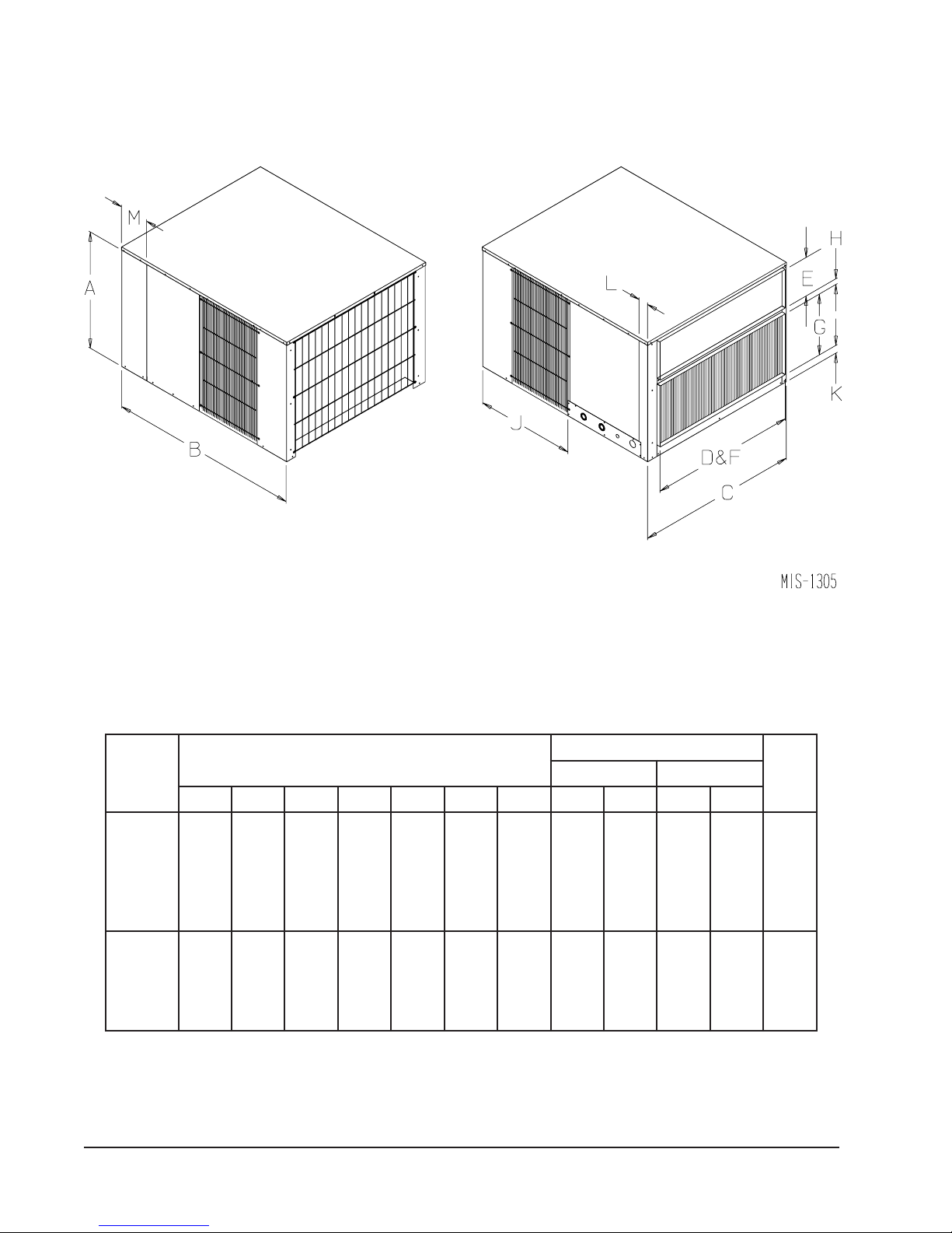
FIGURE 1
UNIT DIMENSIONAL DRAWING
TABLE 5
DIMENSIONS OF UNIT
)sehcnI(gninepOtcuD
ledoM
.oN
ABCJKLMDEFG
4211HP
4221HP
0311HP
0321HP
6311HP
6321HP
2411HP
2421HP
8411HP
8421HP
0601HP
4/1-4261/3-848/1-838/1-628/1-261/961/933633418/7
4/1-130524623
)sehcnI(snoisnemiDtenibaClanimoN
4/3-261/9-7830183618/3-1
egrahcsiDriAnruteR
H
Manual 2100-354F
Page 10 of 32
Page 11

INSTALLATION
LOCATION
GENERAL
The unit must be located outside, or in a well ventilated
area. It must not be in the space being heated or cooled. A
sound absorbing material should be considered if the unit is
to be installed in such a position or location that might
cause transmission of sound or vibration to the living area
or adjacent buildings.
SLAB MOUNTING
In areas where winter temperatures DO NOT go below
32°F for periods over twelve hours, the unit may be slab
mounted at grade level. When installing unit at grade level,
install on a concrete slab at least four inches above finished
grade level. Slab should have a slope tolerance away from
the building structure of at lease ¼ inch per foot, while
being level from side to side. This will prevent ice buildup
under the unit during defrost cycles. Place slab in a
location where runoff water from higher ground will not
collect around unit. See Figure 2.
A minimum of 18 inches should be provided between the
coil inlet and any building surfaces. Provide at least four
feet between coil outlet and any building wall, fences or
other vertical structures. Provide a minimum of three feet
clearance on the service access side of the unit. See
Figure 3.
ROOF MOUNTING
When a unit is installed in areas where low ambient
temperatures or strong winter winds exist, it should be
placed so prevailing winter winds are not in direct line with
the heat pump coil. If this is not possible, a wind barrier
should be constructed. Place barrier 24 inches from the
coil inlet side of the unit and in the direction of prevailing
winds. Size barrier at least the same height and width as
the unit. This may be necessary on ground level
installations, also. See Figure 4.
TYPICAL INSTALLATIONS
1.
ROOF MOUNTED
base on the roof of the building. Return air to the unit
is brought through a single return grille (grilles with
built-in filters are best since they enable easy access for
filter changing). Return air ducts are attached to the
lower section of the front panel. Supply air is brought
from the unit to attic duct work or to a furred down
hall. Supply air duct is attached to the top of the front
panel.
CAUTION: All outdoor duct work must be thoroughly
insulated and weatherproofed. All attic duct work
must be thoroughly insulated. 2-inch thick
insulation with suitable vapor barrier is
recommended for both outdoor and attic runs.
In roof top installation, as in all installations, the heat
pump must be level from side-to-side. However, the
unit should have a pitch along the length to assure
complete external drainage of precipitation and of
defrost condensate. See Figures 6 and 7, and Tables 6
and 7.
CRAWL SPACE
2.
space must be well insulated and provided with a vapor
barrier. In addition, the crawl space must be
thoroughly ventilated and provided with a good vapor
barrier as a ground cover. It is most desirable to install
the unit outdoors rather than inside the crawl space, so
that it will be readily accessible for service. In
addition, it is necessary to dispose of the condensate
from the outdoor coil on the heating cycle, and this is
virtually impossible with the unit installed inside the
crawl space.
SLAB MOUNTED AT GROUND LEVEL
3.
type installation is ideal for homes with a slab floor
construction where a roof mounted unit is not desired.
The supply and return duct work can be run through a
furred closet space.
– The unit is mounted on a sturdy
– Duct work installed in crawl
– This
WINTER INSTALLATION BELOW 32°F
In areas where winter conditions go below 32°F for
extended periods, the unit must be elevated above the
mounting surface to prevent snowfall or defrost ice
accumulation from interfering with the operation of the
unit. A minimum of twelve inches elevation is
recommended, while greater elevation may be required for
areas of high snow accumulation. Poured concrete, steel
framework, brick, cement block, etc., can be utilized to
construct a suitable raised mounting platform. See
Figure 5.
THROUGH THE WALL
4.
requires a suitable framework to be fabricated capable
of withstanding the unit weight. Normally the unit will
be insulated so as to minimize supply and return duct
work.
– This type installation
Manual 2100-354F
Page 11 of 32
Page 12

FIGURE 2
SLAB MOUNTING AT GROUND LEVEL
(Above 32°F Outside Temperature)
FIGURE 3
AIRFLOW AND SERVICE ACCESS CLEARANCES
Manual 2100-354F
Page 12 of 32
Page 13
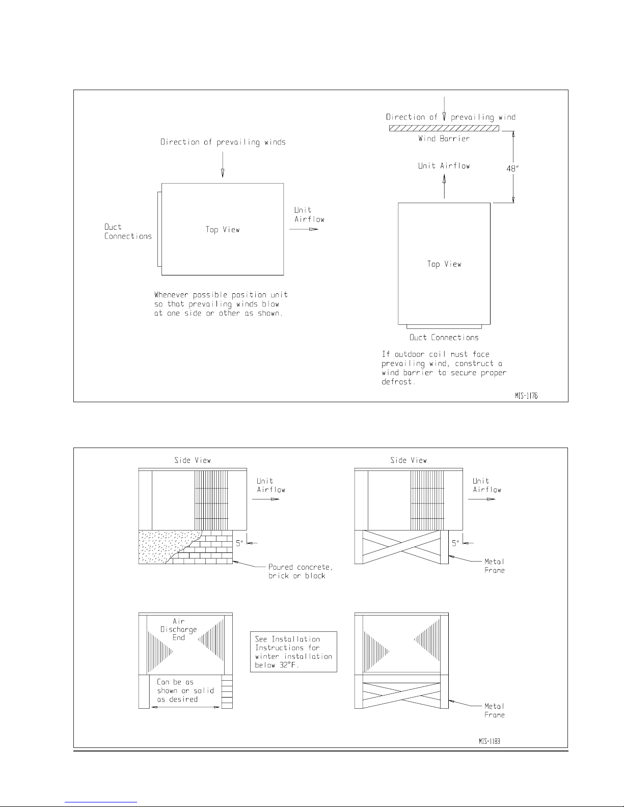
FIGURE 4
ROOF TOP APPLICATION
(May also be required for ground level installations)
FIGURE 5
ELEVATED MOUNTING PLATFORMS
Manual 2100-354F
Page 13 of 32
Page 14
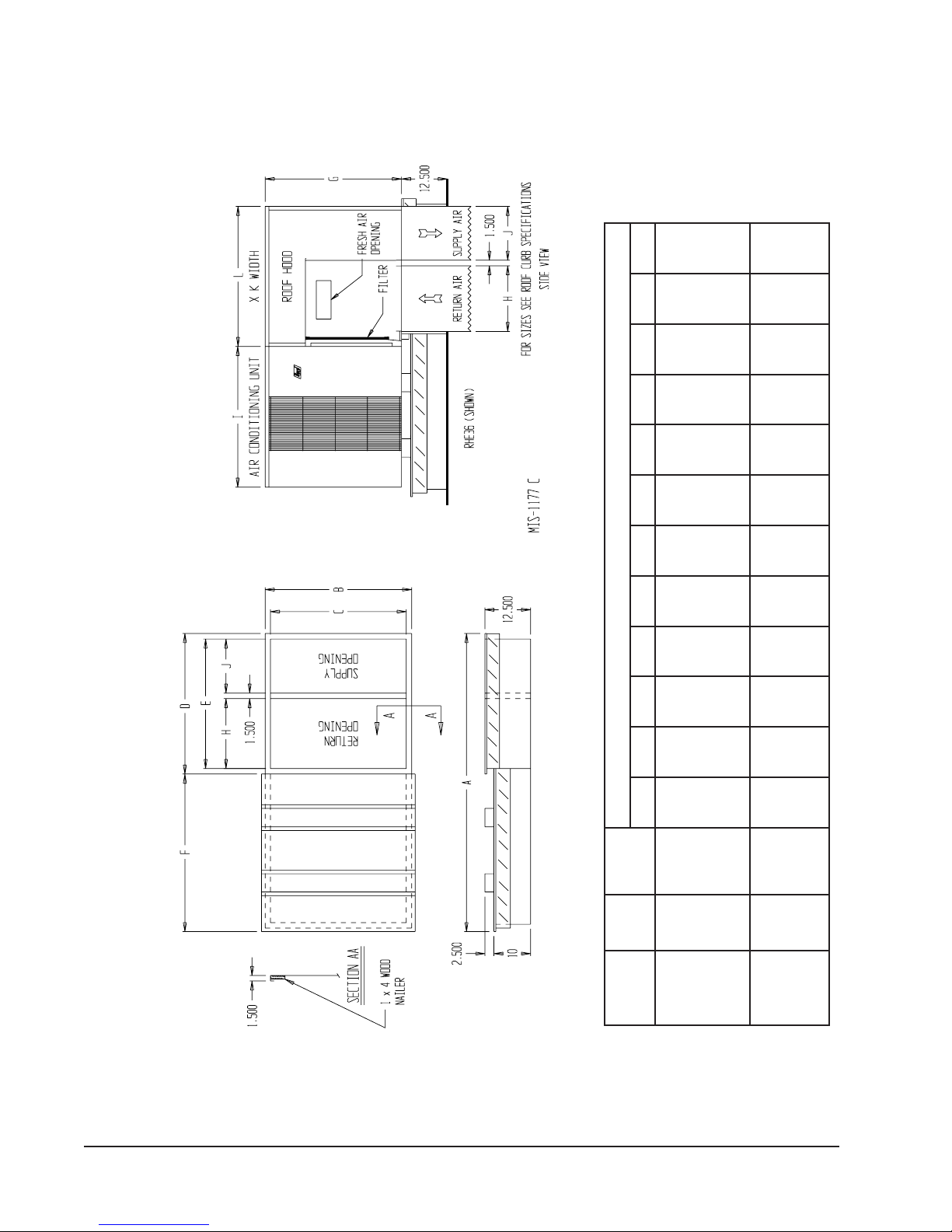
sliateDbruCfooR
FIGURE 6
TABLE 6
ROOF CURB DIMENSIONS
PREFABRICATED ROOF CURB SPECIFICATIONS
ONE PIECE CONSTRUCTION – READY TO INSTALL
fooR
HEAVY GAUGE GALVANIZED WITH WOOD NAILING STRIP, WELDED/LEAKPROOF
fooR
ABCDEFGH I JKL
ledoM
bruC
ledoM
dooH
ledoMtinU
63-EHR300-2409573.0852.0452.73573.83573.532452.42521.91881.8457.41521.8352.83
*4221HP
*0321HP
*4211HP
*6321HP
*0311HP
*6311HP
06-EHR400-2409573.28521.44521.14573.83573.534452.13521.910557.412452.83
*0601HP
*2421HP
*8401HP
*8421HP
*2411HP
Revision Level
*
Manual 2100-354F
Page 14 of 32
Page 15
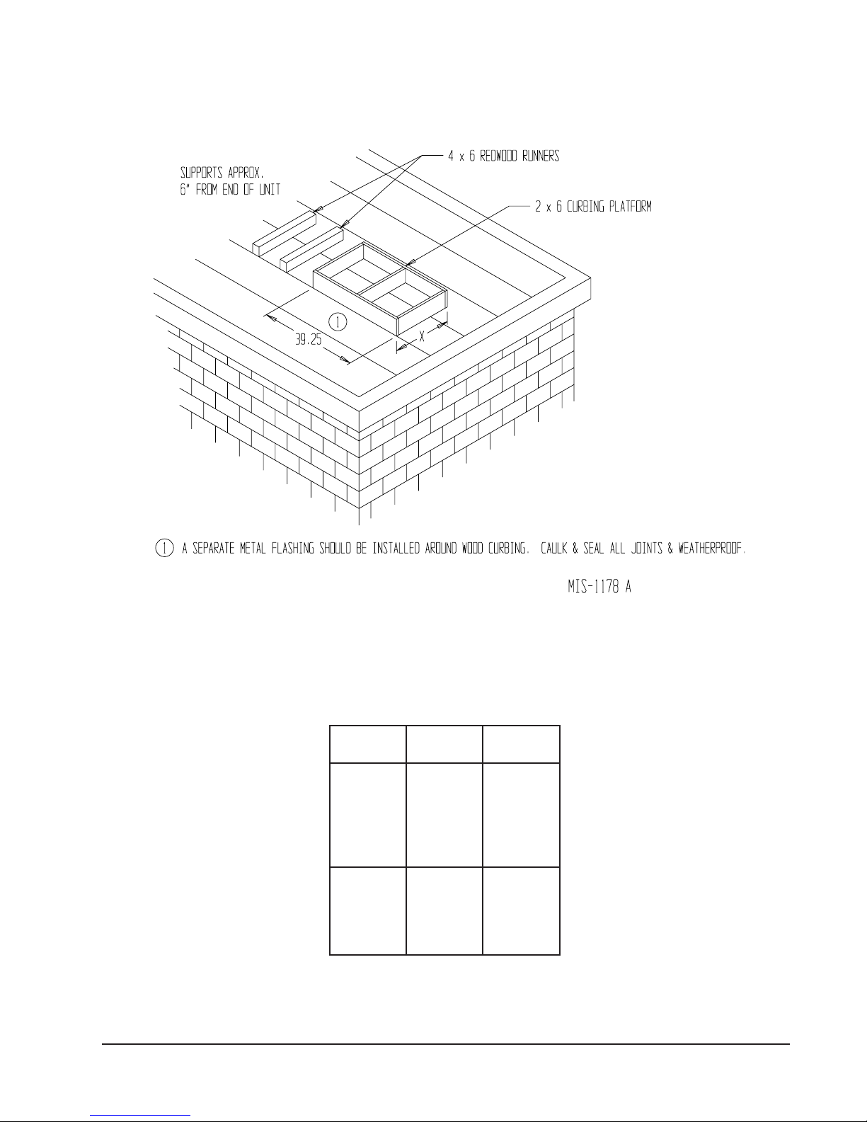
FIGURE 7
FIELD FABRICATED CURBING
TABLE 7
DIMENSION “X” FOR FIELD
FABRICATED CURBING
ledoMtinU
4211HP
4221HP
0311HP
0321HP
6311HP
6321HP
2411HP
2421HP
8401HP
8421HP
0601HP
dooHfooR
ledoM
63-EHR14
06EHR8/7-44
X
noisnemiD
Manual 2100-354F
Page 15 of 32
Page 16
OTHER INSTALLATIONS
5.
– Many other
installations are possible with the packaged heat
pump. No matter what the installation, always
consider the following facts:
A. Insure that the discharge air is not obstructed in
any way so as to cause operation difficulties.
B. The indoor coil drain pan is equipped with a
coupling that must be piped through a condensate
drain trap to a suitable drain.
C. Always mount the unit in such a position that it
may be easily reached for servicing and
maintenance.
D. Insure that the unit is clear so that proper airflow
over the outdoor coil will be maintained.
If this unit is operated in cooling below a 65° outdoor
ambient temperature, the installation of low ambient
controls (CMA-6) to unit is required.
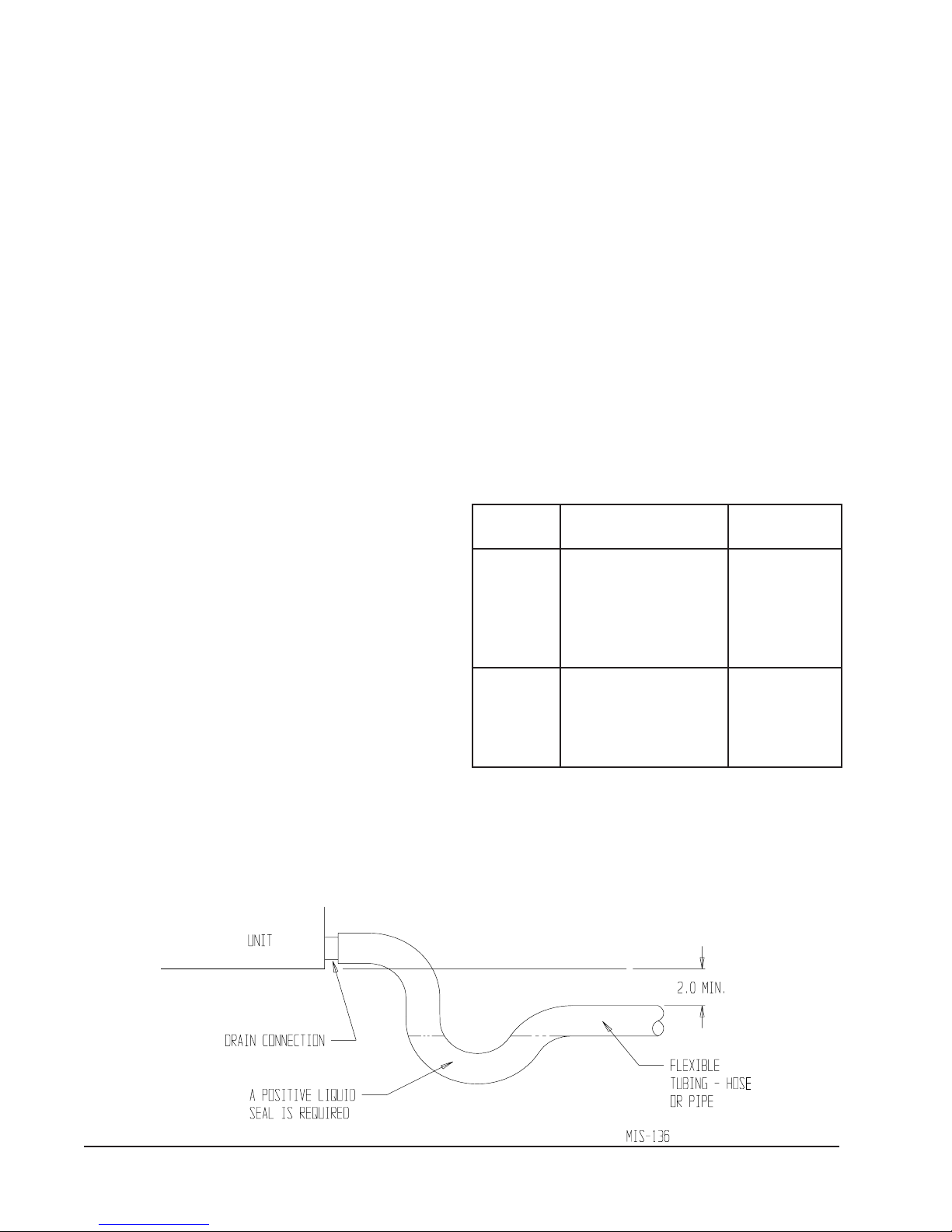
CONDENSATE DRAIN TRAP
It is very important to provide a trap in the condensate
drain line to allow a positive liquid seal in the line and
assure correct drainage from the coil condensate pan.
Install condensate drain trap shown in Figure 8. Use drain
connection size or larger. Do not operate unit without
trap. Unit must be level or slightly inclined toward drain.
With a trap installed on a unit located in an unconditioned
area, water in the trap may freeze. It is recommended that
the trap material be of a type that will allow for expansion
of water when it freezes.
AIR FILTERS
Air filters for the return air side of the system are not
provided as part of the various types of applications for
these models, and must be field supplied and installed as
part of the final installation.
Prior thought should be given to return air location and
placement of the air filter(s). The air filter(s) must be of
adequate size and readily accessible to the operator of the
equipment. Filters must be adequate in size and properly
maintained for proper operation. If this is not done,
excessive energy use, poor performance, and multiple
service problems will result. It is impossible to oversize air
filters. Generous sizing will result in cleaner air and coils
as well as lower operating costs and extend the time
between required changes. Table 8 shows minimum filter
areas and recommended filter sizes. Actual filter sizes can
vary with the installation due to single or multiple returns
utilizing a filter/grille arrangement or being placed
immediately ahead of the indoor coil face in the return air
duct.
TABLE 8
FILTERS REQUIRED AND SIZE
.oNledoMaerAretliFmuminiM
4211HP
4221HP
0311HP
0321HP
6311HP
6321HP
2411HP
2421HP
8401HP
8421HP
0601HP
sehcnIerauqS264
)teeFerauqS12.3(
sehcnIerauqS806
)teeFerauqS26.4(
eziS
dednemmoceR
1x8/5-03x51
1x02x61)2(
Manual 2100-354F
Page 16 of 32
NOTE: If roof hood accessory is to be used, information
on air filters may be found under that heading in
this manual. Air filters are supplied as part of
that package.
FIGURE 8
CONDENSATE DRAIN TRAP
Page 17
WIRING – MAIN POWER
Refer to the unit rating plate for wire sizing information
and maximum fuse size. Each outdoor unit is marked with
a “Minimum Circuit Ampacity”. This means that the field
wiring used must be sized to carry that amount of current.
If field installed heaters are added to the basic unit, a
second separate power supply circuit will be required. The
heater rating plate located adjacent to the basic unit rating
plate will show the appropriate circuit ampacity fuse size,
etc. (Also see “Electrical Data” on pages 3, 4 and 5.) All
models are suitable for connection with copper wire only.
These instructions must be adhered to. Refer to the
National Electrical Code for complete current carrying
capacity data on the various insulation grades of wiring
material.
LOW VOLTAGE WIRING
The unit rating plate lists a “Maximum Time Delay Fuse”
or “HACR” type circuit breaker that is to be used with the
equipment. The correct size must be used for proper circuit
protection and also to assure that there will be no nuisance
tripping due to the momentary high starting current of the
compressor.
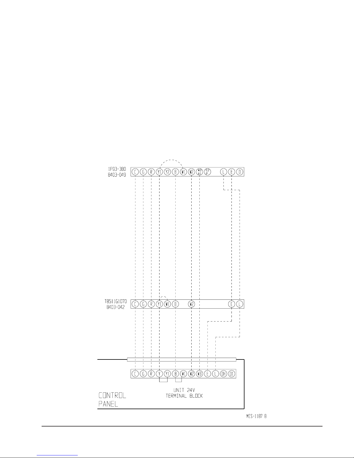
WIRING – 24V LOW VOLTAGE
CONTROL CIRCUIT
Nine (9) wires should be run from thermostat subbase to
the 24V terminal board in the unit. A nine conductor,
18 gauge copper, color-coded thermostat cable is
recommended. The connection points are shown in
Figure 9.
FIGURE 9
Manual 2100-354F
Page 17 of 32
Page 18
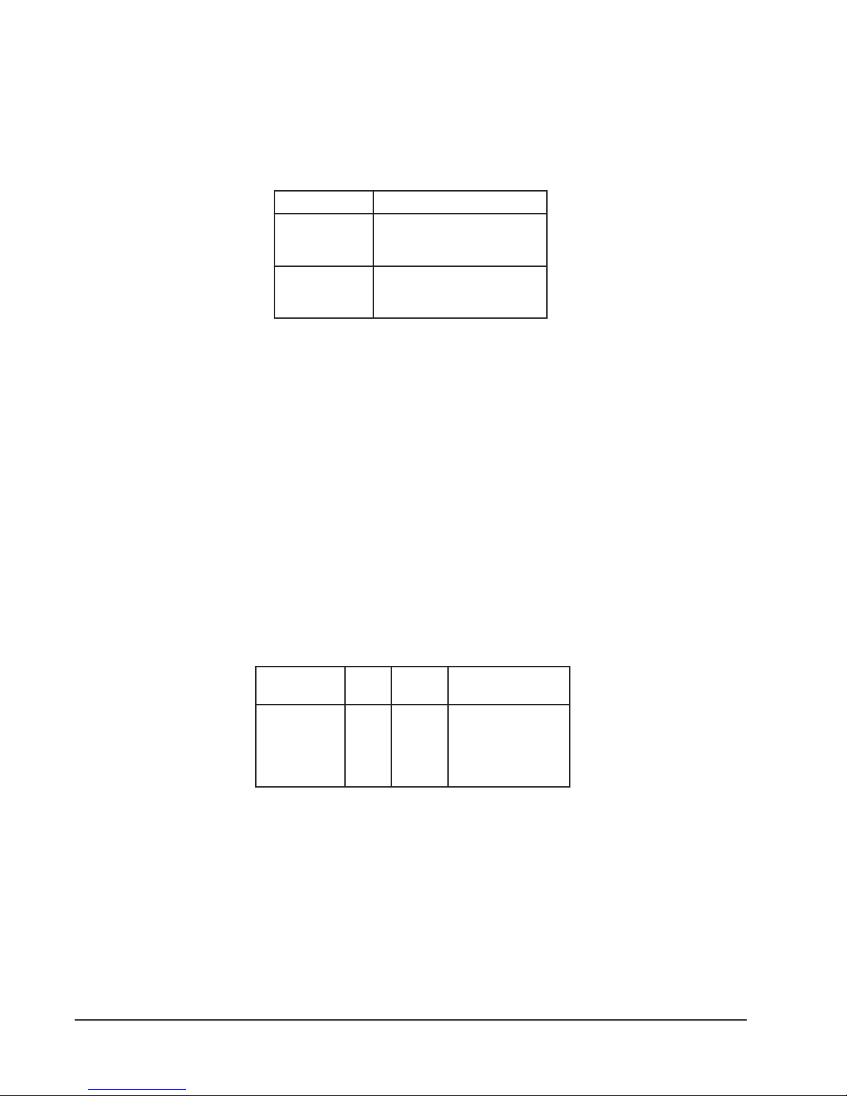
THERMOSTATS
See specific wiring information for the different models, heater KWs, and voltages.
TABLE 9
HEAT PUMP THERMOSTATS
tatsomrehTserutaeFtnanimoderP
940-3048
)083-39F1(
850-3048
)1511D0225HT(
IMPORTANT NOTE: Only the thermostats shown above are recommended for use with this equipment.
taeHegats2;looCegats2
cinortcelEelbammargorP
revoegnahclaunaMrootuA
taeHegats2;looCegats2
elbammargorP-noNcinortcelE
revoegnahclaunaMrootuA
Manual 2100-354F
Page 18 of 32
TABLE 10
THERMOSTAT WIRE SIZE
remrofsnarT
AV
553.202
ALF
eriW
eguaG
54
81
61
41
21
06
htgneLmumixaM
teeFnI
001
061
052
Page 19
THERMOSTAT INDICATOR LAMPS
The red lamp marked “EM. HT.” comes on and stays on
whenever the system switch is placed in Em. Ht. position.
The green lamp marked “Check” will come on if there is
any problem that prevents the compressor from running
when it is supposed to be.
EMERGENCY HEAT POSITION
The operator of the equipment must manually place the
system switch in this position. This is done when there is a
known problem with the outdoor section, or when the green
“Check” lamp comes on indicating a problem.
TRANSFORMER TAPS
230/208V, 1 phase and 3 phase equipment employ dual
primary voltage transformers. All equipment leaves the
factory wired on 240V tap. For 208V operation, reconnect
from 240V to 208V tap. The acceptable operating voltage
range for the 240 and 208V taps are:
TAP RANGE
240 253 – 216
208 220 – 187
NOTE: The voltage should be measured at the field power
connection point in the unit and while the unit is
operating at full load (maximum amperage
operating condition).
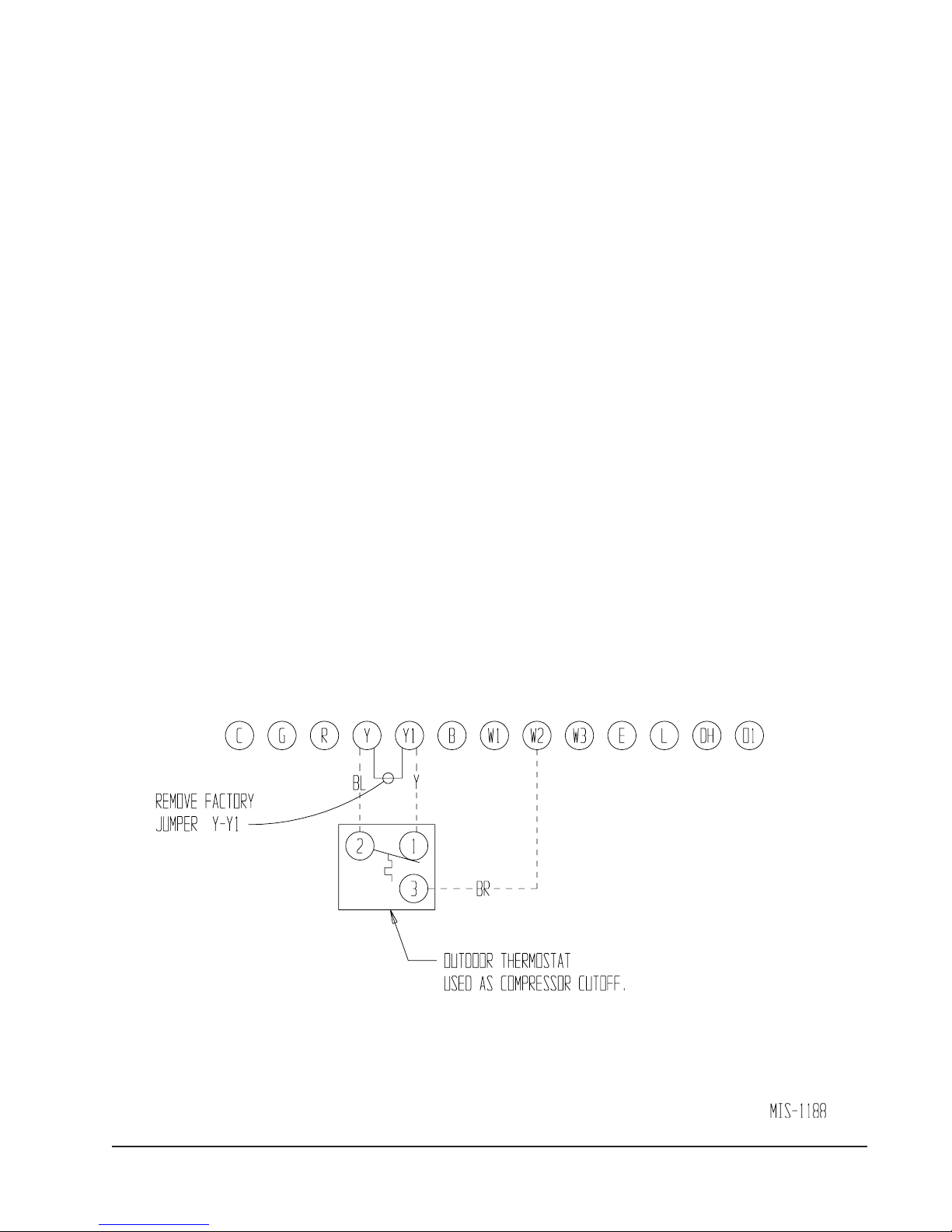
COMPRESSOR CUTOFF THERMOSTAT
and OUTDOOR THERMOSTAT WIRING
Heat pump compressor operation at outdoor temperatures
below 0°F are neither desirable not advantageous in terms
of efficiency. Since most equipment at time of
manufacture is not designated for any specific destination
of the country and most of the equipment is installed in
areas not approaching the lower outdoor temperature range,
the compressor cutoffs are not factory installed.
Outdoor thermostats are available to hold off various banks
of electric heat until needed as determined by outdoor
temperature. The set point of either type of thermostat is
variable with geographic region and sizing of the heating
equipment to the structure. Utilization of the Heating
Application Data and the heat loss calculation of the
building are useful in determining the correct set points.
Refer to Installation Instructions of CMH-14 Outdoor
Thermostat Kit for more information.
FIGURE 10
UNIT 24V TERMINAL BOARD (5 THROUGH 10 KW)
Manual 2100-354F
Page 19 of 32
Page 20
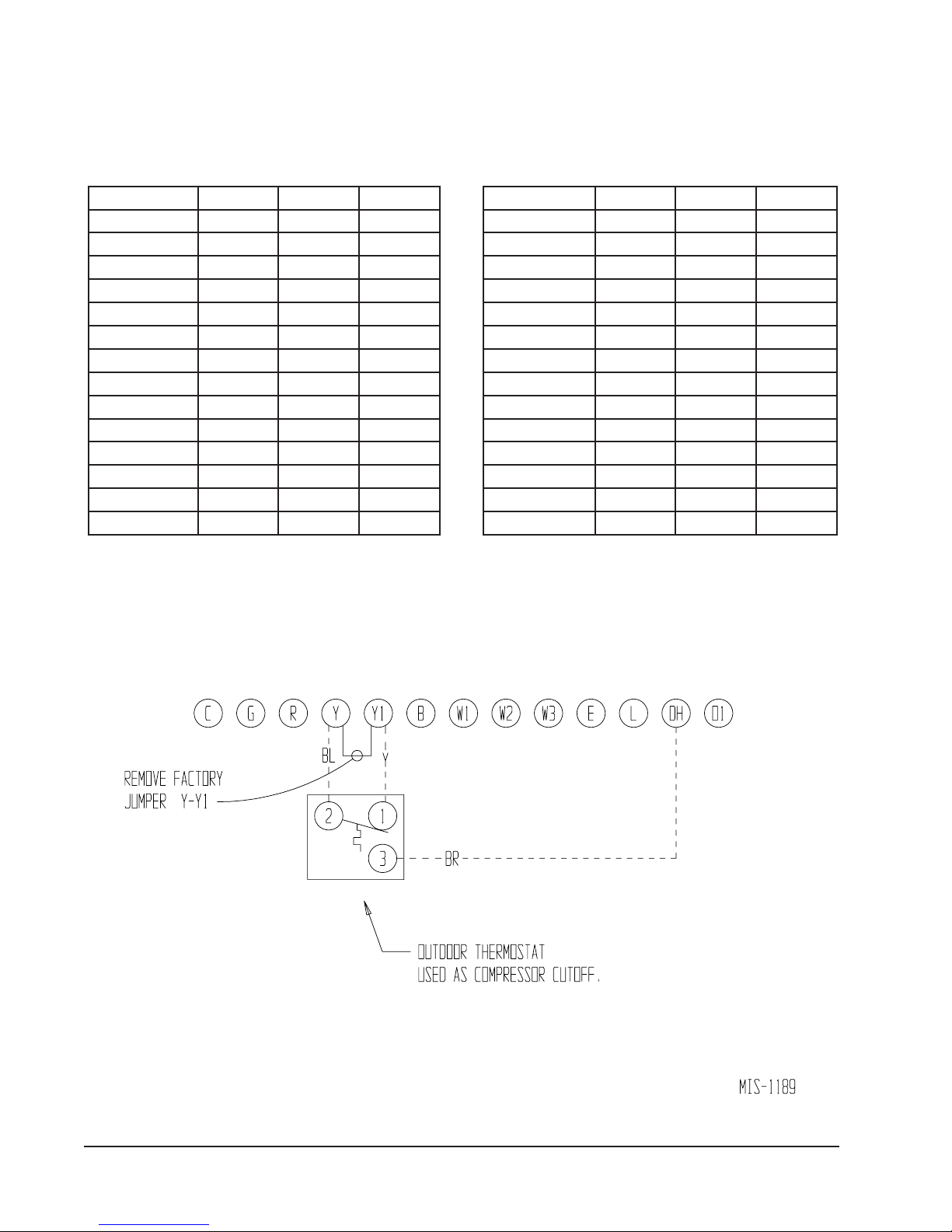
COMPRESSOR CUTOFF THERMOSTAT
WIRING (5 through 10 KW) (FIGURE 10)
COMPRESSOR CUTOFF THERMOSTAT
WIRING (15 through 20 KW) (FIGURE 11)
TABLE 11
5 through 10 KW
ledoMWKstloVesahP
24211HP8,5,00321
14221HP01,5,00321
10311HP8,5,00321
0321HP01,5,00321
16311HP8,5,00321
6321HP01,5,00321
22411HP01,5,00321
2421HP01,5,00321
18401HP01,5,00321
C-,B-18401hP9,0064/0323
18421HP01,5,00321
B-18421HP9,00323
0601HP01,5,00321
C-,B-0601HP9,0064/0323
TABLE 12
15 through 20 KW
ledoMWKstloVesahP
24211HP510321
14221HP510321
10311HP510321
0321HP510321
16311HP510321
6321HP510321
22411HP02,510321
2421HP510321
18401HP02,510321
C-,B-18401HP81,51064/0323
18421HP510321
B-18421HP510321
0601HP02,510321
C-,B-0601HP81,51064/0323
FIGURE 11
UNIT 24V TERMINAL BOARD (15 through 20 KW)
Manual 2100-354F
Page 20 of 32
Page 21

START UP AND OPERATION
THREE PHASE SCROLL COMPRESSOR
START UP INFORMATION
Scroll compressors, like several other types of compressors,
will only compress in one rotational direction. Direction of
rotation is not an issue with single phase compressors since
they will always start and run in the proper direction.
However, three phase compressors will rotate in either
direction depending upon phasing of the power. Since
there is a 50-50 chance of connecting power in such a way
as to cause rotation in the reverse direction, verification of
proper rotation must be made. Verification of proper
rotation direction is made by observing that suction
pressure drops and discharge pressure rises when the
compressor is energized. Reverse rotation also results in an
elevated sound level over that with correct rotation, as well
as, substantially reduced current draw compared to
tabulated values.
Verification of proper rotation must be made at the time
the equipment is put into service. If improper rotation is
corrected at this time there will be no negative impact on
the durability of the compressor. However, reverse
operation for over one hour may have a negative impact on
the bearing due to oil pump out.
NOTE: If compressor is allowed to run in reverse rotation
for several minutes the compressor’s internal
protector will trip.
SEQUENCE OF OPERATION
COOLING
compressor contactor starting the compressor and outdoor
motor. The G (indoor motor) circuit is automatically
completed on any call for cooling operation, or can be
energized by manual fan switch on subbase for constant air
circulation.
HEATING
controls heating cycle operation. Two thermostat options,
one allowing “AUTO” changeover from cycle to cycle and
the other constantly energizing solenoid coil during heating
season and thus eliminating pressure equalization noise
except during defrost, are to be used. On “AUTO” option,
a circuit is completed from R-W1 and R-Y on each heating
“On” cycle energizing reversing valve solenoid and pulling
in compressor contactor starting compressor and outdoor
motor. R-G also make starting indoor blower motor. Heat
pump heating cycle now in operation. The second
energizes the reversing valve solenoid constantly whenever
the system switch on subbase is placed in “Heat” position,
the “B” terminal being constantly energized from R. A
thermostat demand for heat completes R-Y circuit, pulling
in compressor contactor starting compressor and outdoor
motor. R-G also make starting indoor blower motor.
– Circuit R-Y makes at thermostat pulling in
– A 24V solenoid coil on reversing valve
All three phase ZR*3 compressors are wired identically
internally. As a result, once the correct phasing is
determined for a specific system or installation, connecting
properly phased power leads to the same Fusite terminals
should maintain proper rotation direction.
The direction of rotation of the motor may be changed by
reversing any two line connections to the unit.
Manual 2100-354F
Page 21 of 32
Page 22
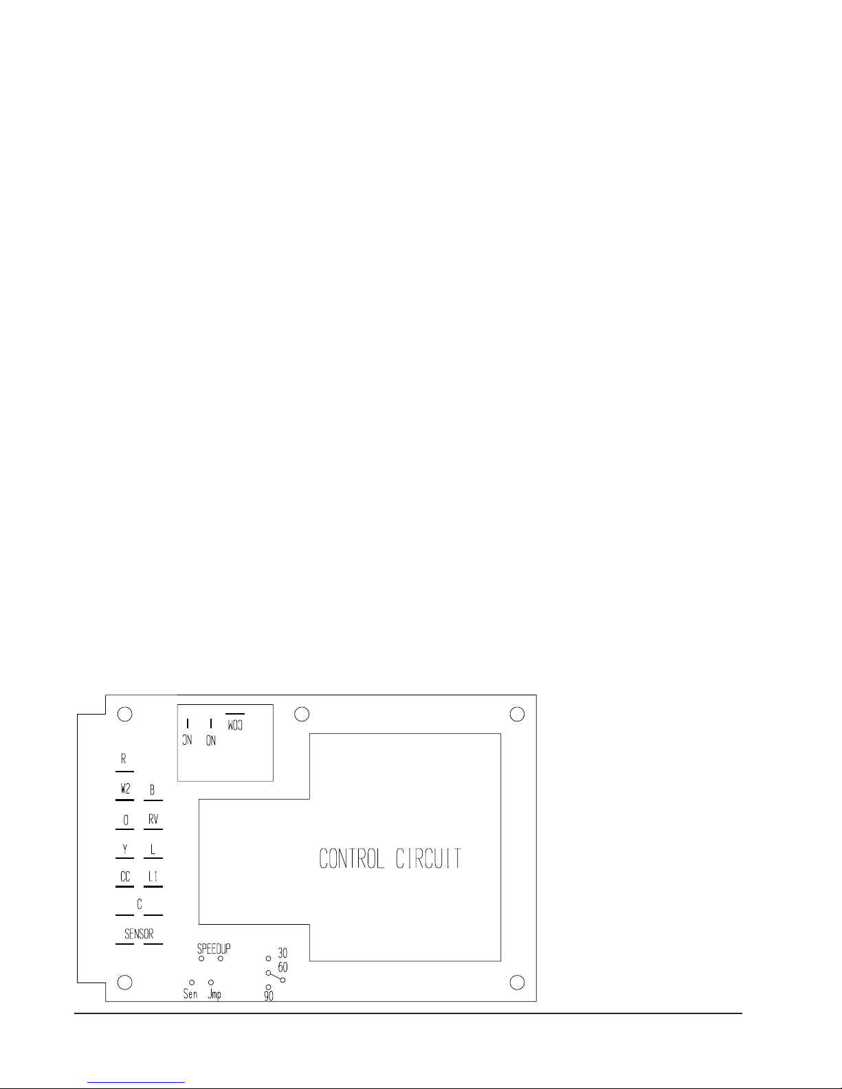
DEFROST CYCLE
The defrost cycle is controlled by temperature and time on
the solid state heat pump control. See Figure 12.
When the outdoor temperature is in the lower 40°F
temperature range or colder, the outdoor coil temperature is
32°F or below. This coil temperature is sensed by the coil
sensor mounted near the bottom of the outdoor coil. Once
coil temperature reaches 30°F or below, the coil sends a
signal to the control logic of the heat pump control and the
defrost timer will start.
There is a cycle speed up jumper on the control. This can
be used to reduce the time between defrost cycle operation
without waiting for time to elapse.
Use a small screwdriver or other metallic object, or another
1/4 inch QC to short between the SPEEDUP terminals to
accelerate the HPC timer and initiate defrost.
Be careful not to touch any other terminals with instrument
used to short the SPEEDUP terminals. It may take up to 10
seconds with the SPEEDUP terminals shorted for the
speedup to be completed and the defrost cycle to start.
After 30 minutes at 30°F or below, the heat pump control
will place the system in the defrost mode.
During the defrost mode, the refrigerant cycle switches
back to the cooling cycle, the outdoor motor stops, electric
heaters are energized, and hot gas passing through the
outdoor coil melts any accumulated frost. When the
temperature rises to approximately 57°F the coil sensor will
send a signal to the heat pump control which will return the
system to heating operations automatically.
If some abnormal or temporary condition such as a high
wind causes the heat pump to have a prolonged defrost
cycle, the heat pump control will restore the system to
heating operation automatically after 10 minutes.
There are three settings on the heat pump control – 30, 60
and 90 minutes. Models are shipped wired on the 60-minute
setting for greatest operating economy. If special
circumstances require a change to another time, remove wire
connected to terminal 60 and reconnect to desired terminal.
Refer to Figure 12. The manufacturer’s recommendation is
for 60-minute defrost cycles.
FIGURE 12
HEAT PUMP CONTROL BOARD
As soon as the defrost cycle kicks in remove the shorting
instrument from the SPEEDUP terminals. Otherwise the
timing will remain accelerated and run through the 1-minute
maximum defrost length sequence in a matter of seconds and
will automatically terminate the defrost sequence.
There is an initiate defrost jumper (sen jump) on the control
that can be used at any outdoor ambient during the heating
cycle to simulate a 0° coil temperature. This can be used to
check defrost operation of the unit without waiting for the
outdoor ambient to fall into the defrost region.
By placing a jumper across the SEN JMP terminals (a 1/4
inch QC terminal works best) the defrost sensor mounted
on the outdoor coils is shunted out and will activate the
timing circuit. This permits the defrost cycle to be checked
out in warmer weather conditions without the outdoor
temperature having to fall into the defrost region.
In order to terminate the defrost test in the SEN JMP
jumper must be removed. If left in place too long the
compressor could stop due to the high pressure control
opening because of the high pressure condition created by
operating in the cooling mode with outdoor fan off.
Pressure will rise fairly fast as there is likely no actual frost
on the outdoor coil in this artificial test condition.
There is also a 5-minute compressor time delay function
built into the HPC. This is to
protect the compressor from
instances it is helpful to the
service technician to override or
speed up this timing period, and
shorting out the speedup terminals
for a few seconds can do this.
Manual 2100-354F
Page 22 of 32
MIS-1191
Page 23
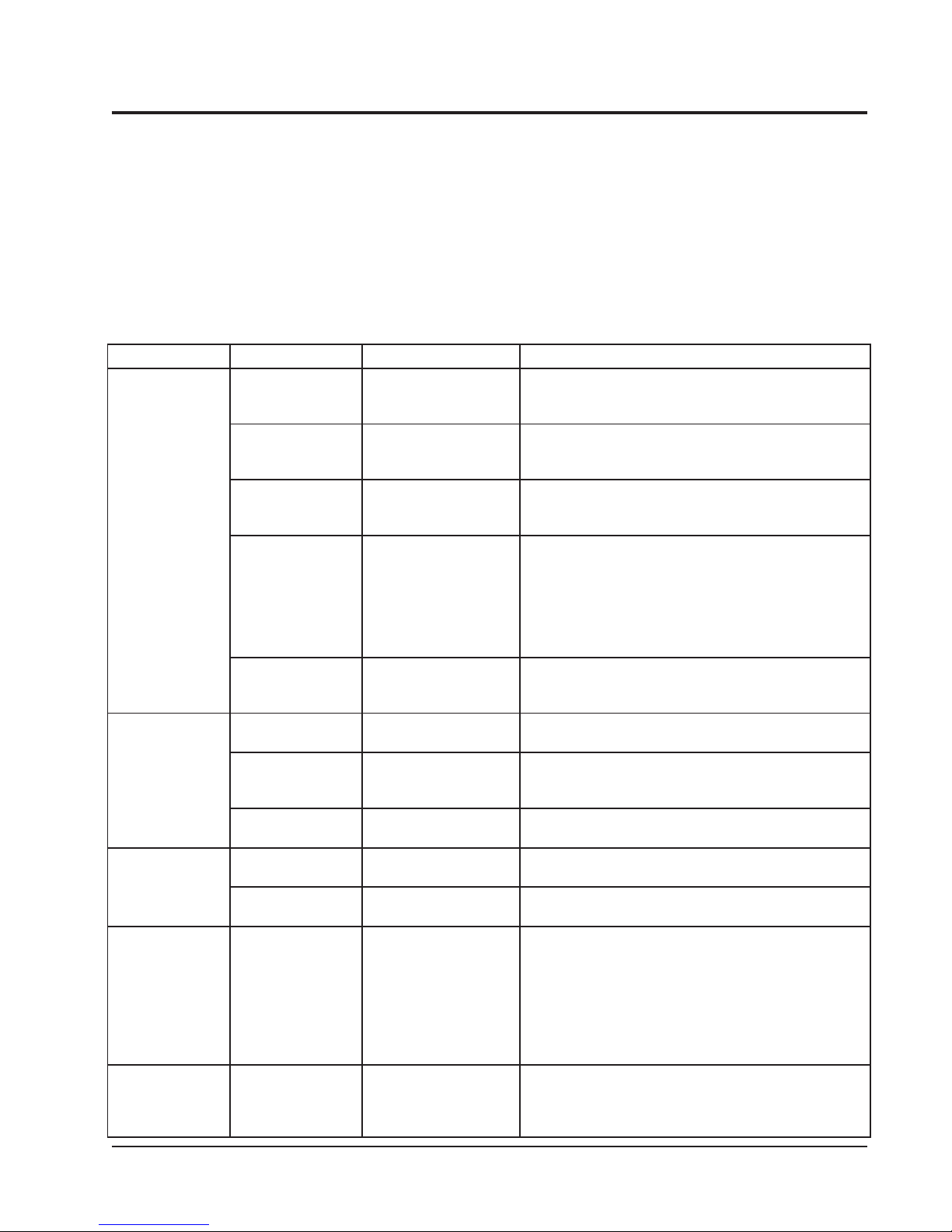
TROUBLESHOOTING
SOLID STATE HEAT PUMP CONTROL
TROUBLESHOOTING PROCEDURE
1. Turn on AC power supply to unit.
2. Turn thermostat blower switch to fan on. The indoor
blower should start. (If it doesn’t, troubleshoot indoor
unit and correct problem.)
3. Turn thermostat blower switch to Auto position.
Indoor blower should stop.
TROUBLESHOOTING
motpmySsesuaCelbissoPkcehCottahWriapeRrokcehCotwoH
tonlliwrosserpmoC
rognitaehnitrats
gnilooc
evitcefed
rotomroodtuonaF
nurtonseod
gnitaehrognilooc(
)tsorfedgnirudtpecxe
seodevlavgnisreveR
ezigreneton
)ylnognitaeh(
otniogtonlliwtinU
tsorfed
)ylnognitaeh(
tuoemoctonlliwtinU
tsorfedfo
)ylnognitaeh(
evitcefed
evitcefed
evitcefed
evitcefed
.evitcefed
gniriWtiucriClortnoCnoCotRmorfV42rofkcehC
gniriWtiucriClortnoCnoCotYmorfV42rofkcehC
gniriWtiucriClortnoCCCotCmorfV42rofkcehC
tuokcolrosserpmoCtuokcolrosserpmoC -hgihehtkcehcl,ortnocpmuptaehehtfo1LtatneserptonsiV42fI
lortnocpmuptaeH
evitcefedrotoMdetrohsroneporofkcehC
roticapacrotoM
.roticapac
lortnocpmuptaeH
dionelosevlovgnisreveR
evitcefedlioc
lortnocpmuptaeH
lortnocpmuptaeh
lortnocpmuptaeh
.lioc
.C-Bdna
rorosneserutarepmeT
.etunim
rorosneserutarepmeT
4. Set system switch to heat or cool. Adjust thermostat to
call for heat or cool. The indoor blower, compressor,
and outdoor fan should start.
NOTE: If there is no power to 24 volt transformer, the
compressor and outdoor fan motor will not start
for 5 minutes. This is because of the compressor
short cycle protection.
dnaremrofsnartotdraobmorfgniriwkcehc,RtatneserptonsiV42fI
lortnocpmuptaeheht
.remrofsnartecalperdnaesuacenimreted,tuptuoV42
pirtslanimretegatlovwol
.petstxenoteunitnoc,tneserp
lortnocpmuptaehno
.yaledemitetunim-5edirrevootsdnoces01rof
lortnocpmuptaehevitcefeD ,lortnocpmuptaehehtno1LotCdna,YotCmorftneserpsiV42fI
.lortnocpmuptaehehtecalperCCta
.rotomecalpeR
.gnidniwrotom
.gnitarroticapackcehC
detrohsroneporofkcehC
noyalernafssorcakcehC
)CN-moC(.lortnocpmuptaeh
detrohsroneporofkcehC
C-VRneewtebV42rofkcehC
erutarepmettcennocsiD
dnadraobmorfrosnes
pudeepsssorcarepmuj
pmujnesdnaslanimret
esuacdluohssihT.slanimret
ahguorhtogottinueht
enonihtiwelcyctsorfed
pudeepsssorcarepmuJ
esuacdluohssihT.slanimret
.etunimenonihtiw
.lortnoc
tsorfedfotuoemocottinueht
.roticapacecalpeR
.lortnocpmuptaehecalpeR
.liocdionelosecalpeR
.gniriwtiucriclortnockcehC.1
lortnocpmuptaehecalpeR.2
ecalper,elcyctsorfedfotuosemoctinufI.1
.rosneserutarepmet
,elcyctsorfedfotuoemoctonseodtinufI.2
.lortnocpmuptaehecalper
onsahremrofsnartfI.egatlovtuptuodnatupniremrofsnartkcehc
roodtuo,gniriwtatsomrehtdnatatsomrehtkcehc,tneserptonsiV42fI
siV42fI.)deppiuqefi(rotinomesahp)deppiuqefi(tatsomreht
siV42fI.rotcatnocrosserpmocecalperro/&kcehc,tneserpsiV42fI
rosserpmocfI.sdnoces01roflanimretpudeepsehtpmuj,tneserpton
.lortnocpmuptaehehtno1LotCmorfV42rofkcehctratstonseod
lladna)deppiuqefi(yalerssapyberusserp-woldnahctiwserusserp
.tiucricdesolcasitiucricytefasehT.slanimretdnagniriwdetaicossa
eht,nepoerayalerssapyberusserpwolrohctiwserusserphgihehtfI
.tnenopmocevitcefedecalpeR.rosserpmocehttuokcollliwlortnoc
slanimretpudeepspmuJ.tuokcolteserotnodnafforewopelcyC
tneserpsiV42ondnaderipxeroneddirrevoneebsahyaledemiteht
.rosneserutarepmetecalper,elcyctsorfedhguorhtseogtinufI.1
pmuptaehecalper,elcyctsorfedhguorhtogtonseodtinufI.2
Manual 2100-354F
Page 23 of 32
Page 24
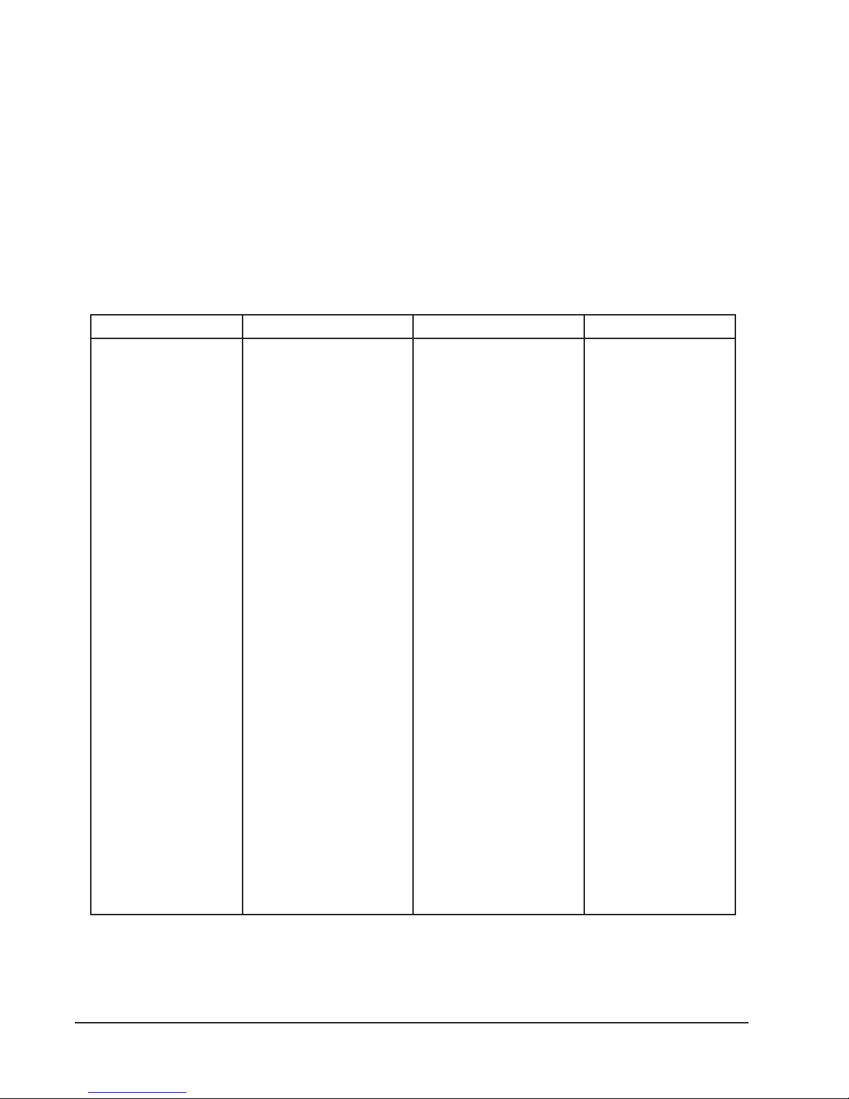
CHECKING TEMPERATURE SENSOR
CHECK OUT
1. Disconnect temperature sensor from board and from
outdoor coil.
2. Use an ohmmeter and measure the resistance of the
sensor. Also use ohmmeter to check for short or open.
3. Check resistance reading to chart of resistance; use
sensor ambient temperature. (Tolerance of part is
± 10%.)
4. If sensor resistance reads very low, then sensor is
shorted and will not allow proper operation of the heat
pump control.
5. If sensor is out of tolerance, shorted, open, or reads
very low ohms then it should be replaced.
TEMPERATURE F VS RESISTANCE R OF TEMPERATURE SENSOR
FR FR FR FR
0.52-
0.42-
0.32-
0.22-
0.12-
0.02-
0.91-
0.81-
0.71-
0.61-
0.51-
0.41-
0.31-
0.21-
0.11-
0.01-
0.9-
0.8-
0.7-
0.6-
0.5-
0.4-
0.3-
0.2-
0.1-
0.0
0.1
0.2
0.3
0.4
0.5
0.6
0.7
0.8
0.9
0.01
0.11
0.21
178691
990091
585381
813771
982171
784561
409951
925451
553941
473441
675931
659431
605031
912621
980221
801811
272411
575011
010701
475301
062001
46079
18939
80019
93188
17358
99628
12108
23677
03257
01927
07607
70586
81466
99346
94426
56506
54785
0.31
0.41
0.51
0.61
0.71
0.81
0.91
0.02
0.12
0.22
0.32
0.42
0.52
0.62
0.72
0.82
0.92
0.03
0.13
0.23
0.33
0.43
0.53
0.63
0.73
0.83
0.93
0.04
0.14
0.24
0.34
0.44
0.54
0.64
0.74
0.84
0.94
0.05
58965
48255
04635
15025
41505
82094
09574
00264
55844
45534
59224
77014
89893
75783
25673
38563
84553
54543
47533
43623
32713
04803
68992
75192
55382
77572
32862
29062
38352
69642
03042
48332
85722
05122
16512
98902
53402
69891
0.35
0.25
0.35
0.45
0.55
0.65
0.75
0.85
0.95
0.06
0.16
0.26
0.36
0.46
0.56
0.66
0.76
0.86
0.96
0.07
0.17
0.27
0.37
0.47
0.57
0.67
0.77
0.87
0.97
0.08
0.18
0.28
0.38
0.48
0.58
0.68
0.78
0.88
47391
76881
57381
98971
43471
48961
74561
22161
01751
01351
12941
44541
77141
02831
47431
73131
01821
29421
38121
38811
19511
70311
13011
26701
10501
74201
00001
0679
6259
9929
7709
2688
3568
9448
0528
7508
9687
6867
0.98
0.09
0.19
0.29
0.39
0.49
0.59
0.69
0.79
0.89
0.99
0.001
0.101
0.201
0.301
0.401
0.501
0.601
0.701
0.801
0.901
0.011
0.111
0.211
0.311
0.411
0.511
0.611
0.711
0.811
0.911
0.021
0.121
0.221
0.321
0.421
7057
4337
5617
0007
0486
3866
1356
3836
9326
8906
1695
7285
7965
0755
6445
6235
8025
4905
2894
3784
7674
3664
2654
4644
7634
4724
2814
3904
6004
1293
8383
7573
8763
1063
6253
2543
Manual 2100-354F
Page 24 of 32
Page 25
SERVICE HINTS
ledoM
detaR
wolfriA
DO°59
erutarepmeT
DO°28
erutarepmeT
24211HP00875-6576-56
14221HP00866-4696-76
0311HP000185-6506-85
0321HP000185-6506-85
6311HP001125-0545-25
6321HP001125-0545-25
2411HP004165-4595-75
2421HP004165-4595-75
8401HP055175-5506-85
8421HP055175-5595-75
0601HP007145-2595-75
1. Caution homeowner to maintain clean air filters at all
times. Also, not to needlessly close off supply and
return air registers. This reduces airflow through the
system, which shortens equipment service life as well
as increasing operating costs.
2. Switching to heating cycle at 75°F or higher outside
temperature may cause a nuisance trip of the manual
reset high pressure switch.
3. The heat pump wall thermostats perform multiple
functions. Be sure that all function switches are
correctly set for the desired operating mode before
trying to diagnose any reported service problems.
4. Check all power fuses or circuit breakers to be sure that
they are the correct rating.
SERVICE
TABLE 13
REFRIGERANT CHARGE
5. Periodic cleaning of the outdoor coil to permit full and
unrestricted airflow circulation is essential.
PRESSURE SERVICE PORTS
High and low pressure service ports are installed on all
units so that the system operating pressures can be
observed. Pressure tables can be found in Tables 16
through 23 in this manual covering all models on both
cooling and heating cycles. It is imperative to match the
correct pressure table to the unit by model number.
REFRIGERANT CHARGE
The correct system R-22 charge is shown on the unit rating
plate. Optimum unit performance will occur with a
refrigerant charge resulting in a suction line temperature
(6" from compressor) as shown in Table 13.
The above suction line temperatures are based upon
80°F dry bulb/67°F wet bulb (50% RH) temperature and
rated airflow across the evaporator during cooling cycle.
FAN BLADE SETTINGS
Shown in Figure 13 are the correct fan blade setting
dimensions for proper air delivery across the outdoor coil.
Any service work requiring removal or adjustment in the
fan and/or motor area will require that the dimensions in
Table 14 be checked and blade adjusted in or out on the
motor shaft accordingly.
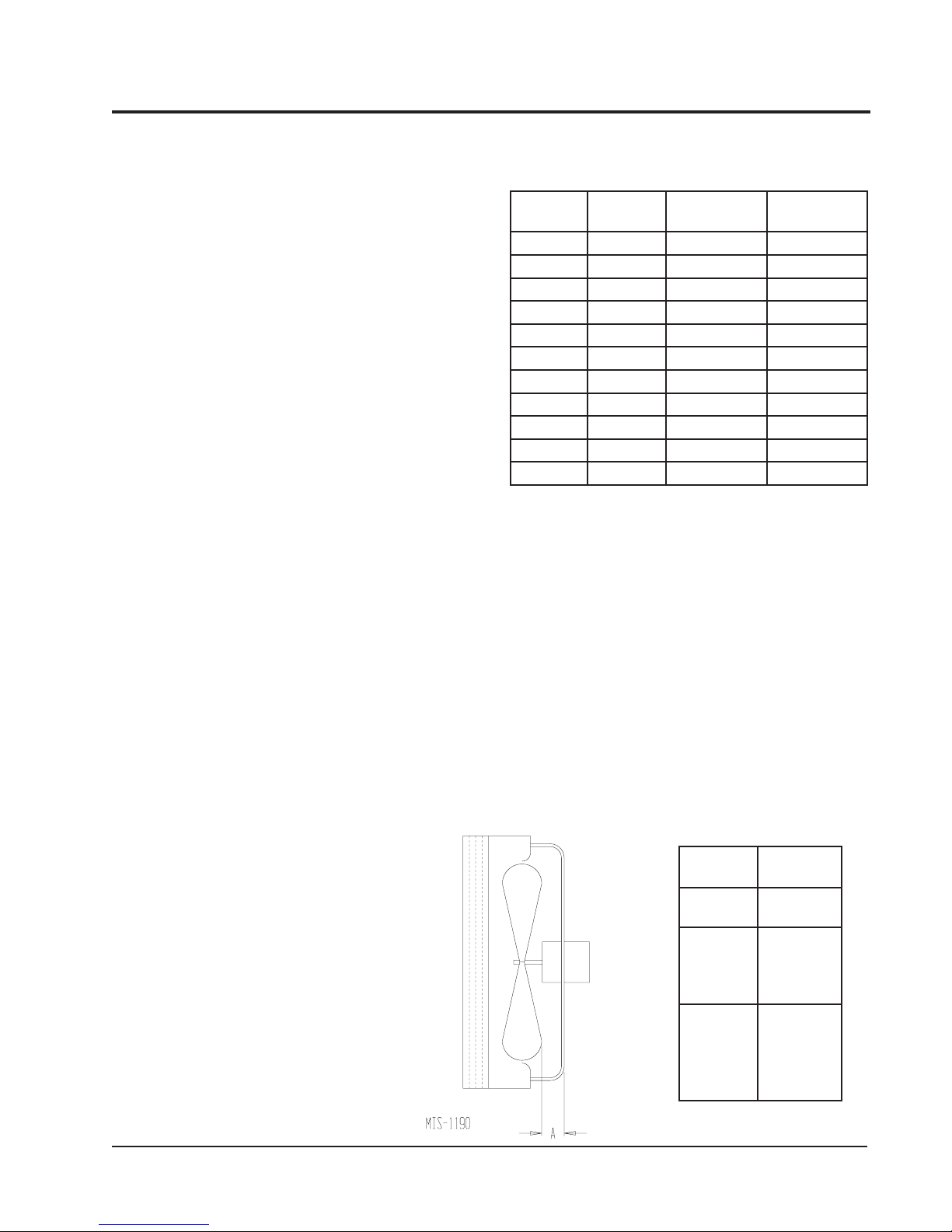
FIGURE 13
FAN BLADE SETTING
TABLE 14
FAN BLADE SETTING
DIMENSIONS
ledoM
4211HP
4221HP
0311HP
0321HP
6311HP
6321HP
22411HP
2421HP
8401HP
8421HP
0601HP
Manual 2100-354F
Page 25 of 32
"A"
"00.1
"57.
"57.1
noisnemiD
Page 26
SUCTION AND DISCHARGE TUBE
BRAZING
Compliant Scroll compressors have copper plated steel
suction and discharge tubes. These tubes are far more
rugged and less prone to leaks than copper tubes used on
other compressors. Due to different thermal properties of
steel and copper, brazing procedures may have to be
changed from those commonly used.
•
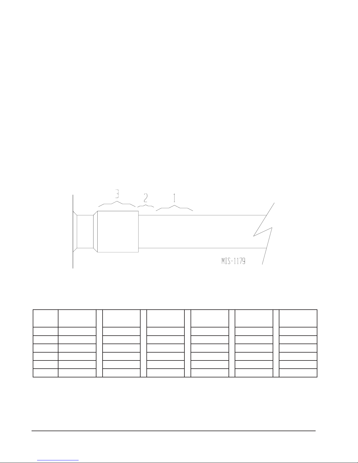
To disconnect: heat joint Areas 2 and 3 slowly and
uniformly until braze material softens and the tube can
be pulled out of suction fitting. (See Figure 14.)
•
To connect:
– Recommended brazing materials: silfos with
minimum 5% silver or silver braze material with
flux.
BRAZING DIAGRAM
– Reinsert tube into fitting.
– Heat tube uniformly in Area 1 moving slowly to
Area 2. When joint reaches brazing temperature,
apply brazing material. (See Figure 14.)
– Heat joint uniformly around the circumference to
flow braze material completely around the joint.
– Slowly move torch into Area 3 to draw braze
material into joint. (See Figure 14.)
– Do not overheat joint.
FIGURE 14
/ niPSE/
0
H
2
0.0/519009/02310521/02310521/05615261/05910291/05810581
1.0/068538/08215711/08215711/00515251/06810381/00810871
2.0/518008/03210011/03210011/53410041/08710571/52710071
3.0/587057/08110001/08110001/04310131/08610661/06615261
4.0/057017/0311059/0311059/03210121/08510551/08510451
5.0/047007/0701098/0701098/02110001/00510841AN
Manual 2100-354F
Page 26 of 32
4211HP
lioCteW/yrD
TABLE 15
INDOOR BLOWER PERFORMANCE
0311HP
lioCteW/yrD
6311HP
lioCteW/yrD
2411HP
lioCteW/yrD
8401HP
lioCteW/yrD
0601HP
lioCteW/yrD
Page 27
TROUBLESHOOTING GE ECM
™
MOTORS
CAUTION:
Disconnect power from unit before removing or replacing
connectors, or servicing motor. To avoid electric shock
from the motor’s capacitors, disconnect power and wait at
least 5 minutes before opening motor.
Symptom Cause/Procedure
Motor rocks slightly • This is normal start-up for ECM
when starting
Motor won’t start • Check blower turns by hand
• No movement
• Motor rocks, • Check for loose or compliant motor mount
but won’t start
Motor oscillates up • It is normal for motor to oscillate with no
load & down while being on shaft
tested off of blower
Motor starts, but
runs erratically
• Varies up and down • Check line voltage for variation or “sag”
or intermittent • Check low voltage connections
• Check power at motor
• Check low voltage (24 Vac R to C) at motor
• Check low voltage connections
(G, Y, W, R, C) at motor
• Check for unseated pins in connectors on
motor harness
• Test with a temporary jumper between R - G
• Check motor for tight shaft
• Perform motor/control replacement check
• Perform Moisture Check
• Make sure blower wheel is tight on shaft
• Perform motor/control replacement check
(G, Y, W, R, C) at motor, unseated pins in
motor harness connectors
• Check “Bk” for erratic CFM command (in
variable-speed applications)
• Check out system controls, Thermostat
• Perform Moisture Check
Symptom Cause/Procedure
• Noisy blower or cabinet • Check for loose blower housing, panels, etc.
• “Hunts” or “puffs” at • Does removing panel or filter reduce
high CFM (speed)
Evidence of Moisture
• Motor failure or • Replace motor and
Check
malfunction has occurred
and moisture is present
• Evidence of moisture • Perform Moisture Check
present inside air mover
• High static creating high blower speed?
- Check for air whistling through seams in
ducts, cabinets or panels
- Check for cabinet/duct deformation
“puffing”?
- Reduce restriction
- Reduce max. airflow
Perform Moisture
Do Don’t
• Check out motor, controls, • Automatically assume the motor is bad.
wiring and connections
thoroughly before replacing
motor
• Orient connectors down so • Locate connectors above 7 and 4 o’clock
water can’t get in positions
- Install “drip loops”
• Use authorized motor and • Replace one motor or control model # with
model #’s for replacement another (unless an authorized replacement)
• Keep static pressure to a • Use high pressure drop filters some have
minimum: H20 drop!
- Recommend high • Use restricted returns
efficiency, low static filters
- Recommend keeping filters
clean.
- Design ductwork for min.
static, max. comfort
- Look for and recommend
ductwork improvement,
where necessary
½"
• “Hunts” or “puffs” at • Does removing panel or filter reduce
high CFM (speed) “puffing”?
• Stays at low CFM • Check low voltage (Thermostat) wires and
despite system call connections
for cool or heat CFM • Verify fan is not in delay mode; wait until
• Stays at high CFM • “R” missing/not connected at motor
• Blower won’t shut off •
Excessive noise • Determine if it’s air noise, cabinet, duct or
• Air noise • High static creating high blower speed?
- Reduce restriction
- Reduce max airflow
delay complete
• “R” missing/not connected at motor
• Perform motor/control replacement check
• Is fan in delay mode? - wait until delay time
complete
• Perform motor/control replacement check
Current leakage from controls into G, Y or W?
Check for Triac switched thermostat or solid state relay
motor noise; interview customer, if necessary
- Is airflow set properly?
- Does removing filter cause blower to slow
down? Check filter
- Use low-pressure drop filter
- Check/correct duct restrictions
• Size the equipment wisely • Oversize system, then compensate with low
airflow
• Check orientation before • Plug in power connector backwards
inserting motor connectors • Force plugs
Moisture Check
• Connectors are oriented “down” (or as recommended by equipment
manufacturer)
• Arrange harness with “drip loop” under motor
• Is condensate drain plugged?
• Check for low airflow (too much latent capacity)
• Check for undercharged condition
• Check and plug leaks in return ducts, cabinet
Comfort Check
• Check proper airflow settings
• Low static pressure for lowest noise
• Set low continuous-fan CFM
• Use humidistat and 2-speed cooling units
• Use zoning controls designed for ECM that regulate CFM
• Thermostat in bad location?
Manual 2100-354F
Page 27 of 32
Page 28
TROUBLESHOOTING GE ECM
™
MOTORS CONT’D.
Replacing ECM Control Module
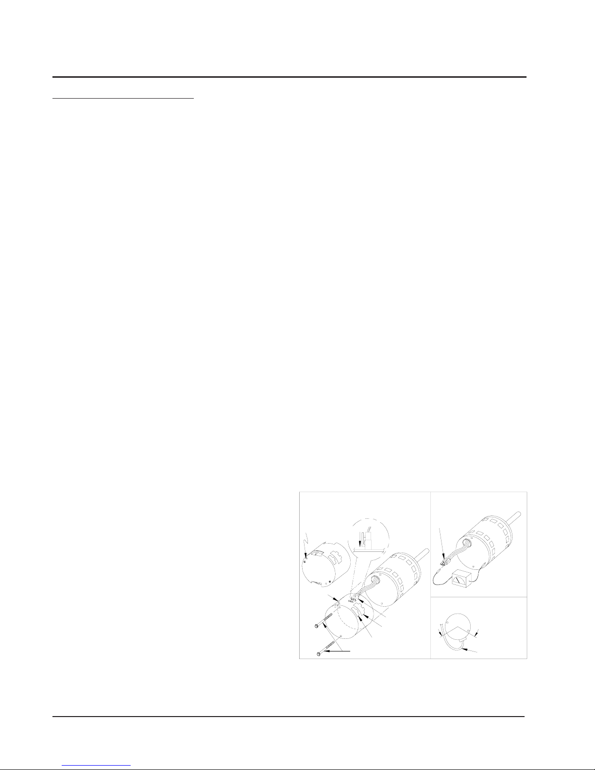
To replace the control module for the GE variable-speed indoor blower
motor you need to take the following steps:
1. You MUST have the correct replacement module. The controls are
factory programmed for specific operating modes. Even though they look
alike, different modules may have completely different functionality.
USING THE WRONG CONTROL MODULE VOIDS ALL PRODUCT
WARRANTIES AND MAY PRODUCE UNEXPECTED RESULTS.
2. Begin by removing AC power from the furnace or air handler being
serviced. DO NOT WORK ON THE MOTOR WITH AC POWER
APPLIED. To avoid electric shock from the motor’s capacitors, disconnect
power and wait at least 5 minutes before opening motor.
3. It is usually not necessary to remove the motor from the blower
assembly. However, it is recommended that the whole blower assembly,
with the motor, be removed from the furnace/air handler. (Follow the
manufacturer’s procedures). Unplug the two cable connectors to the motor.
There are latches on each connector. DO NOT PULL ON THE WIRES.
The plugs remove easily when properly released.
4. Locate the two standard ¼" hex head bolts at the rear of the control
housing (at the back end of the control opposite the shaft end). Refer to
Figure 15. Remove these two bolts from the motor and control assembly
while holding the motor in a way that will prevent the motor or control
from falling when the bolts are removed. If an ECM2.0 control is being
replaced (recognized by an aluminum casting rather that a deep-drawn
black steel can housing the electronics), remove only the hex-head bolts.
DO NOT REMOVE THE TORX-HEAD SCREWS.
5. The control module is now free of mechanical attachment to the
motor endshield but is still connected by a plug and three wires inside
the control. Carefully rotate the control to gain access to the plug at
the control end of the wires. With thumb and forefinger, reach the
latch holding the plug to the control and release it by squeezing the
latch tab and the opposite side of the connector plug and gently pulling
the plug out of the connector socket in the control. DO NOT PULL
ON THE WIRES. GRIP THE PLUG ONLY.
6. The control module is now completely detached from the motor.
Verify with a standard ohmmeter that the resistance from each motor
lead (in the motor plug just removed) to the motor shell is >100K ohms.
Refer to Figure 16. (Measure to unpainted motor end plate.) If any
motor lead fails this test, do not proceed to install the control module.
THE MOTOR IS DEFECTIVE AND MUST BE REPLACED.
Installing the new control module will cause it to fail also.
7. Verify that the replacement control is correct for your application.
Refer to the manufacturer's authorized replacement list. USING THE
WRONG CONTROL WILL RESULT IN IMPROPER OR NO
BLOWER OPERATION. Orient the control module so that the 3-
wire motor plug can be inserted into the socket in the control.
Carefully insert the plug and press it into the socket until it latches. A
SLIGHT CLICK WILL BE HEARD WHEN PROPERLY
INSERTED. Finish installing the replacement control per one of the
three following paragraphs, 8a, 8b or 8c.
8a. IF REPLACING AN ECM 2.0 CONTROL (control in cast
aluminum can with air vents on the back of the can) WITH AN ECM
2.3 CONTROL (control containing black potting for water protection in
black deep-drawn steel case with no vents in the bottom of the can),
locate the two through-bolts and plastic tab that are packed with the
replacement control. Insert the plastic tab into the slot at the perimeter
of the open end of the can so that the pin is located on the inside of the
perimeter of the can. Rotate the can so that the tab inserts into the tab
locater hole in the endshield of the motor. Using the two through-bolts
provided with the replacement control, reattach the can to the motor.
THE TWO THROUGH-BOLTS PROVIDED WITH THE
REPLACEMENT ECM 2.3 CONTROL ARE SHORTER THAN
THE BOLTS ORIGINALLY REMOVED FROM THE ECM 2.0
CONTROL AND MUST BE USED IF SECURE ATTACHMENT
OF THE CONTROL TO THE MOTOR IS TO BE ACHIEVED.
DO NOT OVERTIGHTEN THE BOLTS.
8b. IF REPLACING AN ECM 2.3 CONTROL WITH AN ECM
2.3 CONTROL, the plastic tab and shorter through-bolts are not needed.
The control can be oriented in two positions 180° apart. MAKE SURE
THE ORIENTATION YOU SELECT FOR REPLACING THE
CONTROL ASSURES THE CONTROL'S CABLE CONNECTORS
WILL BE LOCATED DOWNWARD IN THE APPLICATION SO
THAT WATER CANNOT RUN DOWN THE CABLES AND INTO
THE CONTROL. Simply orient the new control to the motor's
endshield, insert bolts, and tighten. DO NOT OVERTIGHTEN THE
BOLTS.
8c. IF REPLACING AN ECM 2.0 CONTROL WITH AN ECM
2.0 CONTROL (It is recommended that ECM 2.3 controls be used for
all replacements), the new control must be attached to the motor using
through bolts identical to those removed with the original control. DO
NOT OVERTIGHTEN THE BOLTS.
9. Reinstall the blower/motor assembly into the HVAC equipment.
Follow the manufacturer's suggested procedures.
10. Plug the 16-pin control plug into the motor. The plug is keyed.
Make sure the connector is properly seated and latched.
11. Plug the 5-pin power connector into the motor. Even though the
plug is keyed, OBSERVE THE PROPER ORIENTATION. DO
NOT FORCE THE CONNECTOR. It plugs in very easily when
properly oriented. REVERSING THIS PLUG WILL CAUSE
IMMEDIATE FAILURE OF THE CONTROL MODULE.
12. Final installation check. Make sure the motor is installed as follows:
a. Unit is as far INTO the blower housing as possible.
b. Belly bands are not on the control module or covering vent holes.
c. Motor connectors should be oriented between the 4 o’clock and
8 o’clock positions when the blower is positioned in its final
location and orientation.
d.Add a drip loop to the cables so that water cannot enter the
motor by draining down the cables. Refer to Figure 17.
The installation is now complete. Reapply the AC power to the HVAC
equipment and verify that the new motor control module is working
properly. Follow the manufacturer's procedures for disposition of the
old control module.
Figure 15 Figure 16
Only remove
Hex Head Bolts
ECM 2.0
Note:
Use the shorter
bolts and
alignment pin
supplied when
replacing an
ECM 2.0
control.
Control Disassembly
Push until
Latch Seats
Over Ramp
ECM
2.3/2.5
Hex-head Screws
Figure 3
From Motor
Circuit
Board
Motor
Motor Connector
(3-pin)
Control Connector
(16-pin)
Power Connector
(5-pin)
Motor Connector
(3-pin)
Back of
Control
Figure 4
Winding Test
R > 100k ohm
Figure 5
Figure 17
Drip Loop
Connector Orientation
Between 4 and 8 o'clock
Drip Loop
Motor OK when
Manual 2100-354F
Page 28 of 32
Page 29
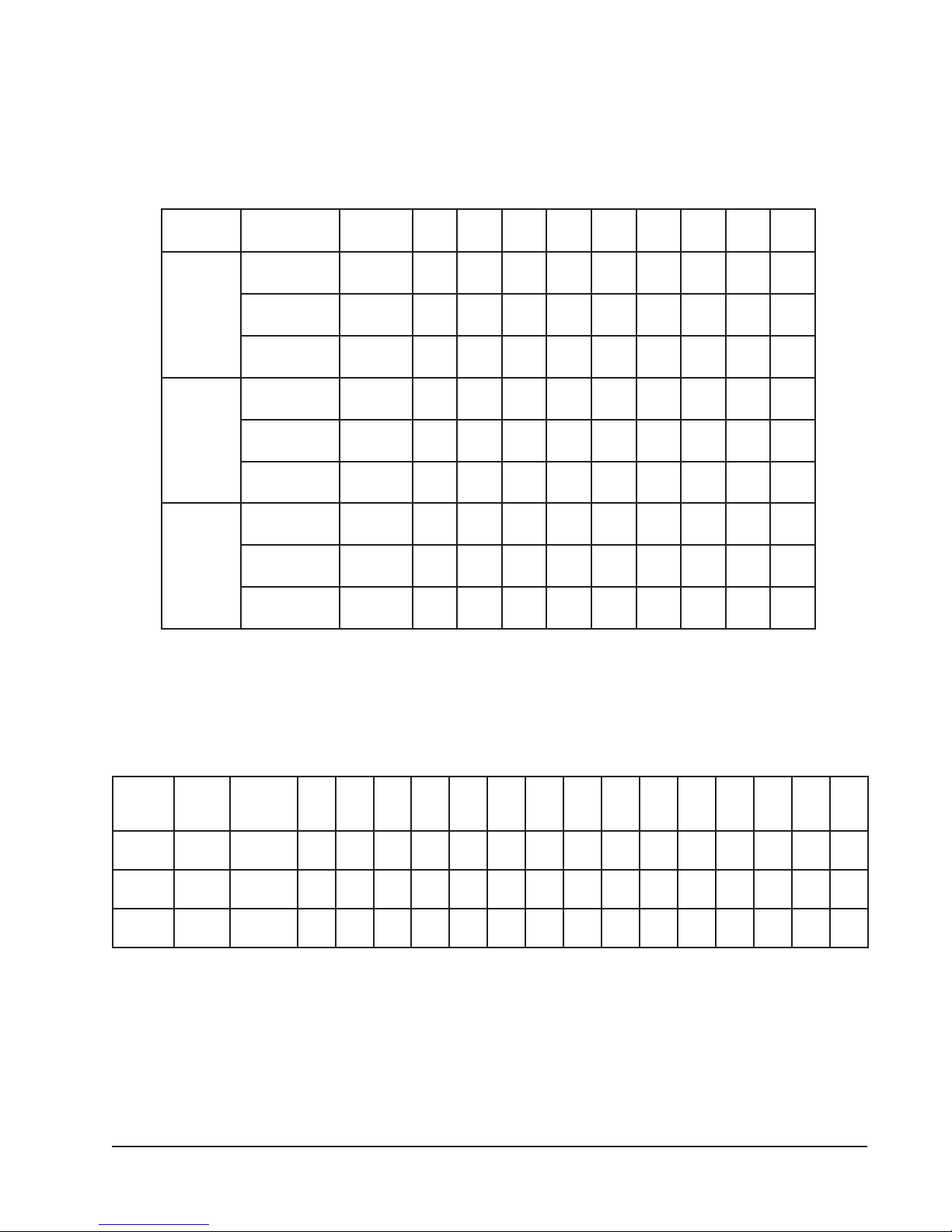
PRESSURE TABLES
TABLE 16
COOLING
Air Temperature Entering Outdoor Coil Degrees F
riAnruteR
ledoM
4211HP
0311HP
6311HP
BD.ged57
BW.ged26
BD.ged08
BW.ged76
BD.ged58
BW.ged27
BD.ged57
BW.ged26
BD.ged08
BW.ged76
BD.ged58
BW.ged27
BD.ged57
BW.ged26
BD.ged08
BW.ged76
BD.ged58
BW.ged27
erutarepmeTerusserP
5708580959001501011511
ediSwoL
37
57
67
77
87
97
ediShgiH
ediSwoL
ediShgiH
ediSwoL
ediShgiH
ediSwoL
ediShgiH
ediSwoL
ediShgiH
ediSwoL
ediShgiH
ediSwoL
ediShgiH
ediSwoL
ediShgiH
ediSwoL
ediShgiH
191
902
722
542
362
97
18
28
38
48
691
512
332
252
072
58
78
88
98
09
302
222
242
162
082
37
47
67
77
97
802
622
542
462
382
77
97
18
38
58
132
232
252
172
092
38
58
78
98
022
042
062
082
003
07
27
37
47
57
902
722
542
262
082
57
77
87
97
08
512
332
152
072
782
08
18
38
48
68
222
042
952
872
792
182
58
882
19
992
18
203
78
903
19
39
023
67
892
18
503
88
613
08
18
38
992
713
553
68
78
98
703
523
443
29
39
59
813
833
753
28
48
58
123
043
853
98
19
39
823
843
763
59
79
99
043
063
083
77
87
08
513
333
28
38
323
98
533
453
153
58
143
953
19
29
273
TABLE 17
HEATING
nruteR
riA
ledoM
4211HPged07
0311HPged07
6311HPged07
Low side pressure ± 2 PSIG
High side pressure ± 5 PSIG
Tables are based upon rated CFM (airflow across the evaporator coil and should be found under section titled “Refrigerant Charge”
elsewhere in manual. If there is any doubt as to correct operating charge being in the system, the charge should be removed,
system evacuated, and recharged to serial plate instructions.
.pmeTerusserP0501517102520353045474055506
ediSwoL
21
61
12
ediShgiH
392
391
ediSwoL
13
ediShgiH
ediSwoL
ediShgiH
82
971
771
14
33
512
991
62
002
702
72
72
671
771
82
52
881
081
Air Temperature Entering Outdoor Coil Degrees F
82
13
63
14
54
05
55
012
412
122
922
632
342
72
82
03
43
93
871
081
481
981
42
42
42
871
671
72
671
971
54
691
502
23
93
681
791
75
052
352
35
65
512
912
84
25
112
812
06
56
752
462
16
17
622
932
95
27
922
152
Manual 2100-354F
Page 29 of 32
07
272
38
452
78
772
Page 30
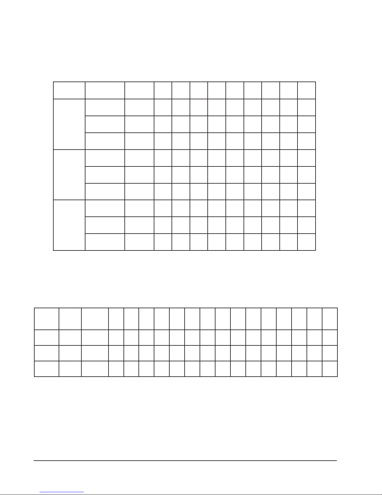
PRESSURE TABLES
TABLE 18
COOLING
Air Temperature Entering Outdoor Coil Degrees F
riAnruteR
ledoM
2411HP
8401HP
0601HP
erutarepmeTerusserP5708580959001501011511
BD.ged57
BW.ged26
BD.ged08
BW.ged76
BD.ged58
BW.ged27
BD.ged57
BW.ged26
BD.ged08
BW.ged76
BD.ged58
BW.ged27
BD.ged57
BW.ged26
BD.ged08
BW.ged76
BD.ged58
BW.ged27
ediSwoL
ediSwoL
ediSwoL
ediSwoL
ediSwoL
ediSwoL
ediSwoL
ediSwoL
ediSwoL
47
57
77
87
97
08
18
28
ediShgiH
291
012
722
442
162
972
692
413
97
08
28
38
48
58
78
88
ediShgiH
791
512
332
052
862
682
403
223
58
68
88
98
09
ediShgiH
402
322
142
952
772
17
37
57
67
77
ediShgiH
ediShgiH
ediShgiH
ediShgiH
ediShgiH
ediShgiH
112
622
342
852
672
67
87
08
18
38
612
232
942
562
382
18
38
68
78
98
422
042
852
472
292
56
66
86
96
07
991
612
532
452
272
07
17
27
37
57
402
222
142
062
972
57
67
77
87
08
112
032
942
962
982
19
49
59
692
513
333
87
97
08
392
013
923
48
58
68
003
813
733
09
19
29
113
923
943
17
27
37
192
903
823
67
77
87
892
713
633
28
38
48
803
823
843
38
233
98
043
69
253
18
743
78
653
49
863
47
543
97
453
58
663
TABLE 19
HEATING
nruteR
riA
ledoM
2411HPged07
8401HPged07
0601HPged07
Low side pressure ± 2 PSIG
High side pressure ± 5 PSIG
Tables are based upon rated CFM (airflow across the evaporator coil and should be found under section titled “Refrigerant
Charge” elsewhere in manual. If there is any doubt as to correct operating charge being in the system, the charge should be
removed, system evacuated, and recharged to serial plate instructions.
.pmeTerusserP0501517102520353045474055506
ediSwoL
71
91
12
62
ediShgiH
651
161
561
ediSwoL
52
72
ediShgiH
061
ediSwoL
71
ediShgiH
651
92
461
861
91
12
461
271
92
961
171
13
23
271
471
42
62
081
381
Air Temperature Entering Outdoor Coil Degrees F
33
83
54
94
25
55
371
771
181
681
391
43
63
83
04
671
081
481
92
33
781
73
591
302
74
881
491
14
64
112
912
65
991
302
45
65
102
402
05
25
622
032
85
702
06
802
55
432
16
46
412
122
76
37
412
122
95
46
342
052
Manual 2100-354F
Page 30 of 32
Page 31
COOLING
PRESSURE TABLES
TABLE 20
Air Temperature Entering Outdoor Coil Degrees F
riAnruteR
ledoM
4221HP
0321HP
6321HP
erutarepmeTerusserP5708580959001501011511
BD.ged57
BW.ged26
BD.ged08
BW.ged76
BD.ged58
BW.ged27
BD.ged57
BW.ged26
BD.ged08
BW.ged76
BD.ged58
BW.ged27
BD.ged57
BW.ged26
BD.ged08
BW.ged76
BD.ged58
BW.ged27
ediSwoL
ediSwoL
ediSwoL
ediSwoL
ediSwoL
ediSwoL
ediSwoL
ediSwoL
ediSwoL
37
57
67
87
97
08
18
28
ediShgiH
ediShgiH
ediShgiH
ediShgiH
ediShgiH
ediShgiH
ediShgiH
ediShgiH
ediShgiH
191
502
912
432
87
08
18
38
691
012
522
042
18
38
48
68
302
712
332
842
37
57
67
87
802
222
732
452
87
08
18
38
312
822
342
062
18
38
48
68
022
632
252
962
27
47
57
77
112
522
242
852
77
97
08
28
612
132
842
562
08
28
38
58
422
932
752
472
152
762
582
303
48
88
78
88
752
472
292
113
78
98
09
19
662
482
203
223
97
97
18
28
072
882
703
623
48
58
78
88
772
592
513
433
78
88
09
19
782
503
623
643
87
97
08
18
672
492
413
333
38
48
68
78
382
203
223
243
68
78
98
09
392
313
333
453
38
323
98
133
29
343
48
643
09
553
39
763
28
553
88
463
19
773
TABLE 21
HEATING
Air Temperature Entering Outdoor Coil Degrees F
nruteR
riA
ledoM
4221HPged07
0321HPged07
6321HPged07
Low side pressure ± 2 PSIG
High side pressure ± 5 PSIG
Tables are based upon rated CFM (airflow across the evaporator coil and should be found under section titled
“Refrigerant Charge” elsewhere in manual. If there is any doubt as to correct operating charge being in the system,
the charge should be removed, system evacuated, and recharged to serial plate instructions.
.pmeTerusserP05015171025203530454740555
ediSwoL
22
42
72
03
13
33
73
14
54
ediShgiH
471
281
091
891
102
502
312
122
ediSwoL
12
32
52
82
92
13
43
ediShgiH
761
071
471
871
971
281
ediSwoL
42
52
62
82
82
ediShgiH
491
591
791
102
03
202
502
83
781
291
33
73
112
812
05
922
732
34
84
791
302
24
74
622
532
65
85
26
542
842
35
55
012
312
35
65
642
052
86
352
162
95
56
712
422
06
86
752
072
Manual 2100-354F
Page 31 of 32
Page 32
COOLING
PRESSURE TABLES
TABLE 22
Air Temperature Entering Outdoor Coil Degrees F
riAnruteR
ledoM
2421HP
8421HP
erutarepmeTerusserP5708580959001501011511
BD.ged57
BW.ged26
BD.ged08
BW.ged76
BD.ged58
BW.ged27
BD.ged57
BW.ged26
BD.ged08
BW.ged76
BD.ged58
BW.ged27
ediSwoL
ediSwoL
ediSwoL
ediSwoL
ediSwoL
ediSwoL
47
67
77
87
97
97
ediShgiH
691
112
522
142
752
472
97
18
28
38
48
58
ediShgiH
ediShgiH
ediShgiH
ediShgiH
ediShgiH
102
612
132
742
462
28
48
58
68
78
88
802
422
932
652
372
27
47
67
77
97
08
302
152
032
542
162
082
77
97
802
08
28
512
922
18
28
48
68
122
632
152
862
782
48
58
78
98
442
062
772
792
18
18
192
803
78
78
182
892
613
09
09
192
803
723
18
38
892
913
78
98
603
723
09
29
713
833
28
623
88
433
19
643
48
043
09
943
39
163
TABLE 23
HEATING
Air Temperature Entering Outdoor Coil Degrees F
nruteR
riA
ledoM
2421HPged07
8421HPged07
Low side pressure ± 2 PSIG
High side pressure ± 5 PSIG
Tables are based upon rated CFM (airflow across the evaporator coil and should be found under section titled
“Refrigerant Charge” elsewhere in manual. If there is any doubt as to correct operating charge being in the system,
the charge should be removed, system evacuated, and recharged to serial plate instructions.
.pmeTerusserP05015171025203530454740555
ediSwoL
62
62
82
03
13
23
63
04
44
ediShgiH
061
461
861
371
471
771
281
781
ediSwoL
62
62
72
82
92
03
33
ediShgiH
561
661
861
071
171
371
73
771
281
94
291
891
14
64
781
491
06
55
85
26
96
402
602
012
25
45
102
85
402
902
77
612
322
56
37
712
722
Manual 2100-354F
Page 32 of 32
 Loading...