

Page 1

INST ALLA TION INSTRUCTIONS
SINGLE P ACKAGE
HEA T PUMPS
MODELS
PH1224
PH1230
PH1236
Bard Manufacturing Company
Bryan, Ohio 43506
Since 1914...Moving ahead, just
as planned.
Manual : 2100-344
File: Volume II Tab 11
Date: 08-21-98
© Copyright 1998
Page 2

Contents
Getting Other Informations and Publications ........ 1
General Instructions................................................. 3
Important ................................................................ 3
Shipping Damage .................................................... 3
General ................................................................ 3
Field-Installed Heater Packages (Optional).............. 3
Installation................................................................. 5
Location ................................................................ 5
Typical Installations .................................................. 5
Condensate Drain Trap............................................ 8
Air Filters ................................................................ 8
Wiring – Main Power................................................ 9
Wiring – 24V Low Voltage Control Circuit................ 9
Thermostats........................................................... 10
Thermostat Indicator Lamps ...................................1 1
Emergency Heat Position .......................................1 1
Transformer Taps....................................................1 1
Compressor Cut-Off Thermostat and Outdoor
Thermostat Wiring ..................................................11
Start Up and Operation .......................................... 12
Three Phase Scroll Compressor Start Up
Information............................................................. 12
Sequence of Operation.......................................... 12
Defrost Cycle ......................................................... 12
Start Up Notes ....................................................... 12
Service and Troubleshooting ................................ 14
Service Hints.......................................................... 14
Pressure Service Ports .......................................... 14
Refrigerant Charge ................................................ 14
Fan Blade Settings................................................. 14
Solid State Heat Pump Control
Troubleshooting Procedure.................................... 14
Troubleshooting Guide ........................................... 15
Checking T emperature Sensor Check Out............. 16
Temperature vs. Resistance of
Temperature Sensor Chart..................................... 16
Suction and Discharge Tube Brazing..................... 17
Pressure T ables ..................................................... 18
Wiring Diagrams ............................................. 19 - 21
Figures
Figure 1 Prefabricated Rood Curb
Specifications .......................................... 4
Figure 2 Field Fabricated Curbing......................... 4
Figure 3 Elevated Mounting Platforms .................. 6
Figure 4 Airflow and Service Access
Clearances .............................................. 6
Figure 5 Roof Top Application ............................... 7
Figure 6 Slab Mounting at Ground Level ............... 7
Figure 7 Condensate Drain Trap ........................... 8
Figure 8 Low Voltage Wiring ................................. 9
Figure 9 Compressor Cut-Off Thermostat
Wiring (5 and 10 KW) ............................11
Figure 10 Compressor Cut-Off Thermostat
Wiring )15 KW ONLY) ...........................11
Figure 11 Heat Pump Control Board..................... 13
Figure 12 Fan Blade Setting Dimensions .............. 14
Figure 13 Brazing Diagram ................................... 17
Tables
Table 1 Electrical Data......................................... 2
T able 2 Optional Field Installed Heater
Packages ................................................ 2
T able 3 Optional Field Installed Heater Table....... 2
Table 4 Rated CFM and Rated ESP.................... 3
Table 5 Air Filter Area and Size ........................... 8
Table 6 Thermostat Wire Size ............................. 9
Table 7 Heat Pump Thermostats ....................... 10
Table 8 V olts, KW and Phase - Compressor
Cut-Off Wiring (5 and 10 KW)...............11
Table 9 V olts, KW and Phase - Compressor
Cut-Off Wiring (15 KW ONLY0 .............11
Table 10 Refrigerant Charge ............................... 14
T able 1 1 Pressure T able - Cooling ....................... 18
T able 12 Pressure Table - Heating....................... 18
Page 3

Getting Other Information and Publications
These publications can help you install the air conditioner or
heat pump. You can usually find these at your local library
or purchase them directly from the publisher. Be sure to
consult current edition of each standard.
National Electrical Code ........................... ANSI/NFPA 70
Standard for the Installation...................... ANSI/NFPA 90A
of Air Conditioning and
Ventilating Systems
Standard for Warm Air .............................ANSI/NFPA 90B
Heating and Air
Conditioning Systems
Load Calculation for .................................ACCA Manual J
Residential Winter and
Summer Air Conditioning
Duct Design for Residential......................ACCA Manual D
Winter and Summer Air Conditioning
and Equipment Selection
For more information, contact these
publishers:
ACCA — Air Conditioning Contractors of America
1712 New Hampshire Ave. N.W.
Washington, DC 20009
Telephone: (202) 483-9370
Fax: (202) 234-4721
ANSI — American National Standards Institute
11 West Street, 13th Floor
New York, NY 10036
Telephone: (212) 642-4900
Fax: (212) 302-1286
ASHRAE — American Society of Heating
Refrigerating, and
Air Conditioning Engineers, Incorporated
1791 Tullie Circle, N.E.
Atlanta, GA 30329-2305
Telephone: (404) 636-8400
Fax: (404) 321-5478
Commercial Low Pressure, ....................... ACCA Manual Q
Low Velocity Duct System Design
Load Calculation For Commercial ............ACCA Manual N
Summer and Winter Air Conditioning
NFPA — National Fire Protection Association
Batterymarch Park
P.O. Box 9101
Quincy, MA 02269-9901
Telephone: (800) 344-3555
Fax: (617) 984-7057
Manual 2100-344
Page 1
Page 4
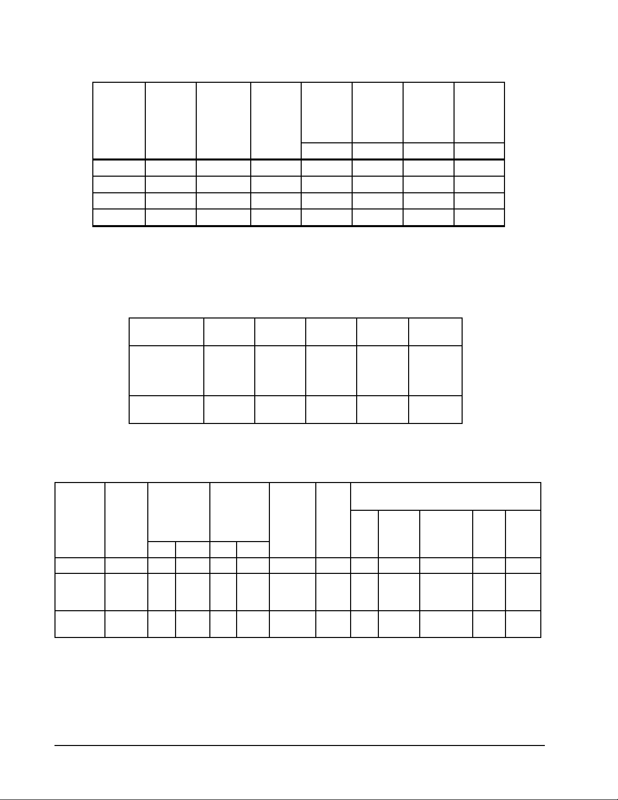
TABLE 1
ELECTRICAL DATA
Q
mumixaM
lanretxE
detaR
&stloV
ledoM
sesahP
gnitarepO
egatloV
egnaR
mumixaM
spmAtinU
rosesuF
.krB.tkC
A.tkCA.tkCA.tkCA.tkC
muminiM
tiucriC
yticapmA
4221HP1-802/032352-7914.4152810101
0321HP1-802/032352-7917.7103220101
6321HP1-802/032352-7918.12047288
B-6321HP3-802/032352-7916.5152910101
Maximum time delay fuse or HACR type circuit breaker. HACR type not applicable to 460 volt.
Q
75 degree C cooper wire size, basic unit only.
R
TABLE 2
OPTIONAL FIELD INSTALLED HEATER PACKAGES
ONLY TO BE USED WITH THE HEAT PUMP MODELS INDICATED
R
dleiF
rewoP
gniriW
R
dnuorG
eziSeriW
egakcaPretaeH
.oNledoM
50A-CP3HE
01A-BP3HE
01A-CP3HE
51A-CP3HE
90B-BP3HE
51B-BP3HE
dnastloV
esahP4221HP0321HP6321HPB-6321HP
X
1/042
X
X
X
X
X
X
X
3/042
X
X
TABLE 3
OPTIONAL FIELD-INSTALLED ELECTRIC HEATER TABLE
&WK.rtH
yticapaC
@
retaeH
ledoM.gkP
.oN
01A-BP3HE
50A-CP3HE
01A-CP3HE
51A-CP3HE
90B-BP3HE
51B-BP3HE
Q
R
S
stloVtinU
esahP
1-802/04201001,4305.7000,627.1413506601
1-802/042
5
1-802/042
01
1-802/042
51
3-802/042
9
3-802/042
51
Time delay fuses or “HACR” type circuit breakers must be used for 60 and smaller sizes. Standard fuses
or circuit breakers are suitable for sizes 70 and larger. 480V circuit breakers are not “HACR” type.
Based on wire suitable for 75° C. Other wiring materials must be rated for marked “Minimum Circuit
Ampacity” or greater.
Based upon T able 250-95 of N.E.C. 1993. See electrical data for basic heat pump for Circuit A wiring
specification requirements.
ro(V042
fiV084
)elbacilppa
@
001,71
001,43
002,15
007,03
002,15
&WK.rtH
@
yticapaC
stloV802
57.3
05.7
52.11
57.6
52.11
008,21
000,62
004,83
000,32
004,83
V042
saV084ro
elbacilppa
spmA.rtH
8.02
7.14
5.2606/03
7.12
2.63
retaeH
.oN
lanretnI
dleiF
sesuF
.stkC
1
1
1
1
1
muminiM
tiucriC
yticapmA
62
35
97
82
64
Q
BtiucriC
R
mumixaM
tnerrucrevO
noitcetorP
03
06
08
03
05
6
4
8
S
dleiF
rewoP
gniriW
01
01
dnuorG
eriW
eziSWKHUTBWKHUTB
01
01
8
01
01
IMPORTANT: While this electrical data is presented as a guide, it is important to electrically connect properly size fuses
and conductor wires in accordance with the National Electrical Code and all existing local codes.
Manual 2100-344
Page 2
Page 5
GENERAL INSTRUCTIONS
IMPORTANT
The equipment covered in this manual is to be installed by
trained, experienced service and installation technicians.
Any heat pump is more critical of proper operating charge
and an adequate duct system than a straight air conditioning
unit. All duct work, supply and return ducts, must be
properly sized for the design air flow requirement of the
equipment. ACCA is an excellent guide to proper sizing.
All duct work or portions thereof not in the conditioned
space should be properly insulated in order to both conserve
energy and prevent condensation or moisture damage.
SHIPPING DAMAGE
Upon receipt of equipment, the carton should be checked for
external signs of shipping damage. If damage is found, the
receiving party must contact the last carrier immediately,
preferably in writing, requesting inspection by the carrier’s
agent.
GENERAL
The refrigerant system is completely assembled and
charged. All internal wiring is complete.
The unit is designed for use with or without duct work.
Flanges are provided for attaching the supply and return
ducts.
These instructions explain the recommended method to
install the air cooled self-contained unit and the electrical
wiring connections to the unit.
These instructions and any instructions packaged with any
separate equipment required to make up the entire heat
pump system should be carefully read before beginning the
installation. Note particularly “Starting Procedure” and any
tags and/or labels attached to the equipment.
FIELD INSTALLED HEATER PACKAGES
(OPTIONAL)
These packaged heat pumps are manufactured without
supplementary electric heaters. Supplementary heaters
EH3P series (to fit PH1224, PH1230, and PH1236) are
available for simple, fast, field installation.
A separate field power circuit is required for the
supplementary heaters.
IMPORTANT: Refer to Table 4 when designing duct
work for maximum available static
pressure with heater installed.
Refer to the electrical data shown on pages 2 and 3 for
proper application information on all available heater
combinations and what units they can be used with. It also
shows the applicable circuit ampacities, fuse size, and wire
size for each heater combination.
Refer to the installation instructions packed with the heater
for details on how to insert it into the basic unit.
TABLE 4
RATED CFM AND
EXTERNAL STATIC PRESSURE (ESP)
WET COIL (COOLING)
detaR
ledoM
4221HP00802.MFC088-086
0321HP000103.MFC0011-577
6321HP001102.MFC0121-577
MFC
detaR
PSE
dednemmoceR
egnaRwolFriA
While these instructions are intended as a general
recommended guide, they do not supersede any national
and/or local codes in any way. Authorities having
jurisdiction should be consulted before the installation is
made.
Manual 2100-344
Page 3
Page 6
MIS-1177
FIGURE 1
PREFABRICATED ROOF CURB SPECIFICATIONS
HEAVY GAUGE GALVANIZED WITH WOOD NAILING STRIP, WELDED/LEAKPROOF
ONE PIECE CONSTRUCTION – READY TO INSTALL
CURB AND ROOF DETAILS
fooR
bruCAB*CDEF *J*H
300-24098/3-084/1-044/1-738/3-838/3-53244/3-418/1-9106EHR
*Duct Sizing Information
Return Air Dimension “C” is length Supply Air Dimension “C” is length
Return Air Dimension “H” is width Supply Sir Dimension “J” is width
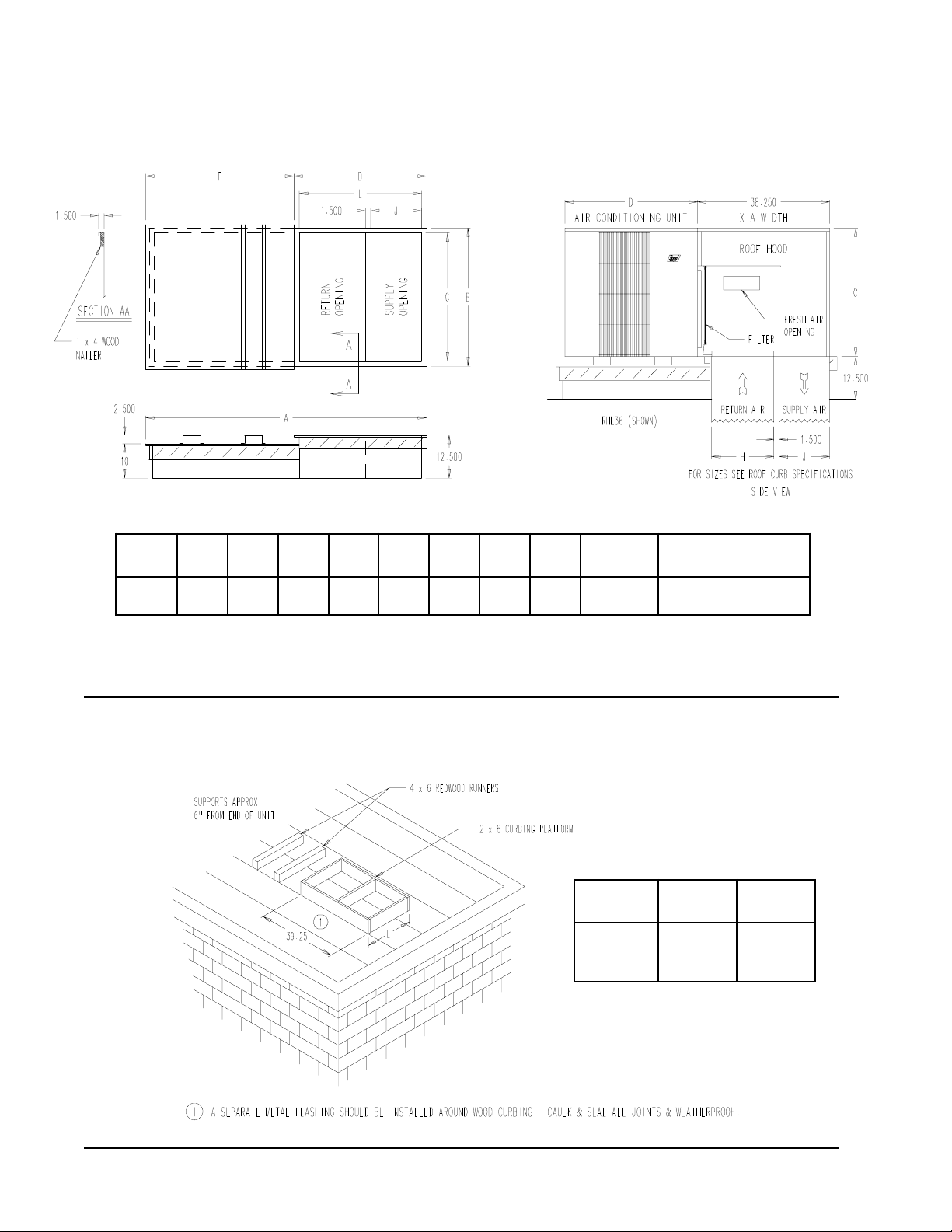
FIGURE 2
FIELD FABRICATED CURBING
dooHfooR
ledoM
dooHfooR
ledoM
tinU
ledoM
gninoitidnoCriA
stinU
,0321HP,4221HP
6321HP
E
4221HP
63EHR
0321HP
14
6321HP
MIS-1178
Manual 2100-344
Page 4
Page 7

INSTALLATION
LOCATION
GENERAL
The unit must be located outside, or in a well ventilated
area. It must not be in the space being heated or cooled. A
sound absorbing material should be considered if the unit is
to be installed in such a position or location that might cause
transmission of sound or vibration to the living area or
adjacent buildings.
SLAB MOUNTING
In areas where winter temperatures DO NOT go below
32° F for periods over twelve hours, the unit may be slab
mounted at grade level. When installing unit at grade level,
install on a concrete slab at least four inches above finished
grade level. Slab should have a slope tolerance away from
the building structure of at lease 1/4 inch per foot, while
being level from side to side. This will prevent ice buildup
under the unit during defrost cycles. Place slab in a location
where runoff water from higher ground will not collect
around unit. See Figure 3.
A minimum of 18 inches should be provided between the
coil inlet and any building surfaces. Provide at least four
feet between coil outlet and any building wall, fences or
other vertical structures. Provide a minimum of three feet
clearance on the service access side of the unit. See
Figure 4
ROOF MOUNTING
When a unit is installed in areas where low ambient
temperatures or strong winter winds exist, it should be
placed so prevailing winter winds are not in direct line with
the heat pump coil. If this is not possible, a wind barrier
should be constructed. Place barrier 24 inches from the coil
inlet side of the unit and in the direction of prevailing winds.
Size barrier at least the same height and width as the unit.
This may be necessary on ground level installations, also.
See Figure 5.
WINTER INSTALLATION BELOW 32°F
In areas where winter conditions go below 32°F for
extended periods, the unit must be elevated above the
mounting surface to prevent snowfall or defrost ice
accumulation from interfering with the operation of the unit.
A minimum of twelve inch elevation is recommended, while
greater elevation may be required for areas of high snow
accumulation. Poured concrete, steel framework, brick,
cement block, etc., can be utilized to construct a suitable
raised mounting platform. See Figure 6.
DUCT WORK
Refer to Tables 4, 5 and 5A when designing duct work for
maximum static pressure available with the specific model
and heater package being installed. Unit duct work is
suitable for 0” clearance to combustible materials.
TYPICAL INSTALLATIONS
1.
ROOF MOUNTED
sturdy base on the roof of the building. Return air to the
unit is brought through a single return grille (grilles with
built-in filters are best since they enable easy access for
filter changing). Return air ducts are attached to the
lower section of the front panel. Supply air is brought
from the unit to attic duct work or to a furred down hall.
Supply air duct is attached to the top of the front panel.
CAUTION: All outdoor duct work must be thoroughly
insulated and weatherproofed. All attic duct work
must be thoroughly insulated. Two inch thick
insulation with suitable vapor barrier is
recommended for both outdoor and attic runs.
In roof top installation, as in all installations, the heat
pump must be level from side to side. However, the unit
should have a pitch along the length to assure complete
external drainage of precipitation and of defrost
condensate.
CRAWL SPACE
2.
space must be well insulated and provided with a vapor
barrier. In addition, the crawl space must be thoroughly
ventilated and provided with a good vapor barrier as a
ground cover. It is most desirable to install the unit
outdoors rather than inside the crawl space, so that it
will be readily accessible for service. In addition, it is
necessary to dispose of the condensate from the outdoor
coil on the heating cycle, and this is virtually impossible
with the unit installed inside the crawl space.
3.
SLAB MOUNTED AT GROUND LEVEL
type installation is ideal for homes with a slab floor
construction where a roof mounted unit is not desired.
The supply and return duct work can be run through a
furred closet space.
4.
THROUGH THE WALL
requires a suitable framework to be fabricated capable of
withstanding the unit weight. Normally the unit will be
insulated so as to minimize supply and return duct work.
5.
OTHER INSTALLATIONS
installations are possible with the packaged heat pump.
No matter what the installation, always consider the
following facts:
A. Insure that the discharge air is not obstructed in any
way so as to cause operation difficulties.
B. The indoor coil drain pan is equipped with a
coupling that must be piped through a condensate
drain trap to a suitable drain.
C. Always mount the unit is such a position that it may
be easily reached for servicing and maintenance.
D. Insure that the unit is clear so that proper air flow
over the outdoor coil will be maintained.
If this unit is operated in cooling below a 65° outdoor
ambient temperature, the installation of low ambient
controls (CMA-6) to unit is required.
– The unit is mounted on a
– Duct work installed in crawl
– This
– This type installation
– Many other
Manual 2100-344
Page 5
Page 8

FIGURE 3
ELEVATED MOUNTING PLATFORMS
MIS-1183
FIGURE 4
AIRFLOW and SERVICE ACCESS CLEARANCES
Manual 2100-344
Page 6
MIS-1185
Page 9

FIGURE 5
ROOF TOP APPLICATION
(May also be required for ground level installations.)
MIS-1176
FIGURE 6
SLAB MOUNTING AT GROUND LEVEL
(Above 32° F Outside Temperature)
MIS-1184
Manual 2100-344
Page 7
Page 10

CONDENSATE DRAIN TRAP
It is very important to provide a trap in the condensate drain
line to allow a positive liquid seal in the line and assure
correct drainage from the coil condensate pan.
Install condensate drain trap shown in Figure 7. Use drain
connection size or larger. Do not operate unit without trap.
Unit must be level or slightly inclined toward drain. With a
trap installed on a unit located in an unconditioned area,
water in the trap may freeze. It is recommended that the trap
material be of a type that will allow for expansion of water
when it freezes.
AIR FILTERS
Air filters for the return air side of the system are not
provided as part of the various types of applications for these
models, and must be field supplied and installed as part of
the final installation.
maintained for proper operation. If this is not done,
excessive energy use, poor performance, and multiple
service problems will result. It is impossible to oversize air
filters. Generous sizing will result in cleaner air and coils
as well as lower operating costs and extend the time
between required changes. Table 6 shows minimum filter
areas and recommended filter sizes. Actual filter sizes can
vary with the installation due to single or multiple returns
utilizing a filter/grille arrangement or being placed
immediately ahead of the indoor coil face in the return air
duct.
TABLE 5
retliFmuminiM
ledoM
4221HP
0321HP
6321HP
saerA
sehcnierauqs264
)teeferauqs12.3(
dednemmoceR
eziS
1x8/5-03x51
Prior thought should be given to return air location and
placement of the air filter(s). The air filter(s) must be of
adequate size and readily accessible to the operator of the
equipment. Filters must be adequate in size and properly
CONDENSATE DRAIN TRAP
NOTE: If roof hood accessory is to be used, information
on air filters may be found under that heading in this
manual. Air filters are supplied as part of that package.
FIGURE 7
Manual 2100-344
Page 8
MIS-136
Page 11

remrofsnarT
AV
ALF
eriW
eguaG
htgneLmumixaM
teeFnI
553.202
81
61
41
21
54
06
001
061
052
WIRING – MAIN POWER
Refer to the unit rating plate for wire sizing information and
maximum fuse size. Each outdoor unit is marked with a
“Minimum Circuit Ampacity”. This means that the field
wiring used must be sized to carry that amount of current. If
field installed heaters are added to the basic unit, a second
separate power supply circuit will be required. The heater
rating plate located adjacent to the basic unit rating plate
will show the appropriate circuit ampacity fuse size, etc.
(Also see “Electrical Data” on pages 2.) All models are
suitable for connection with copper wire only. These
instructions must be adhered to. Refer to the National
Electrical Code for complete current carrying capacity data
on the various insulation grades of wiring material.
The electrical specifications on page 2 lists fuse and wire
sizes (75° F copper) for all models including the most
commonly used heater sizes.
The unit rating plate lists a “Maximum Time Delay Fuse” or
“HACR” type circuit breaker that is to be used with the
equipment. The correct size must be used for proper circuit
protection and also to assure that there will be no nuisance
tripping due to the momentary high starting current of the
compressor.
WIRING – 24V LOW VOLTAGE CONTROL
CIRCUIT
Ten (10 ) wires should be run from thermostat subbase to
the 24V terminal board in the unit. A ten conductor,
18 gauge copper, color-coded thermostat cable is
recommended. The connection points are shown in
Figure 8.
FIGURE 8 – LOW VOLTAGE WIRING
MIS-1187
TABLE 6 – THERMOSTAT WIRE SIZE
Manual 2100-344
Page 9
Page 12

THERMOSTATS
See specific wiring information for the different models, heater KWs, and voltages.
TABLE 7
HEAT PUMP THERMOSTATS
TATSOMREHTESABBUSNOITPIRCSED
540-3048
)1671A148T(
710-3048
)9211R478T(
810-3048
)4201N478T(
240-3048
)0701G1158T(
430-3048
)08-49F1(
720-3048
)17-29F1(
fotraP
tatsomrehT
900-4048
1811L476Q
010-4048
1621F476Q
fotraP
tatsomrehT
fotraP
tatsomrehT
fotraP
tatsomrehT
taeHmE-kcehC:spmaLgnitacidnI
taeHmE-kcehC:spmaLgnitacidnI
revoegnahclaunamrocitamotuA
revoegnahclaunaM;blubyruceM;taehegats2,loocegats1
looC-ffO-taeH-taeHmE:hctiwSmetsyS;nO-otuA:hctiwSnaF
taeHxuA-taeHmE-kcehC:spmaLgnitacidnI
revoegnahclaunaM;blubyrucreM;taehegats2,loocegats1
looC-ffO-taeH-taeHmE:hctiwSmetsyS;nO-otuA:hctiwSnaF
revoegnahcotuA;blubyrucreM;taehegats2,loocegats1
xuA-flaM-pmuP-remE:spmaLgnitacidnI
xuA-flaM-pmuP-remE:spmaLgnitacidnI
Q
R
looC-otuA-taeH-taeHmE-ffO:hctiwSmetsyS;nO-otuA:hctiwSnaF
)deriuqeryrettabon(elbammargorp-nonlatigiD;taehegats2,loocegats1
taeH/looCrootuA-taeHmE-ffO:hctiwSmetsyS;nO-otuA:hctiwSnaF
taeHxuA-taeHmE:noitacidnIyalpsiDkcehC:spmaLgnitacidnI
pukcabyrettaB;)yad7(elbammargorplatigiD;taehegats2,loocegats2
sruoh42repdoirepkcab-tes/pu-tes1;revoegnahclaunamrocitamotuA
yrevocerygrenerorezimonoceroflanimretnoitalitnevelbammargorP
taeH/looCrootuA-taeHmE-ffO:hctiwSmetsyS;nO-otuA:hctiwSnaF
pukcabyrettaB;)yad2/yad5(elbammarforplatigiD;taehegats3,loocegats2
sruoh42repsdoirepkcab-tes/spu-tes4:revoegnahclaunamrocitamotuA
taeH/looCrootuA-taeHmE-ffO:hctiwSmetsyS;nO-otuA:hctiwSnaF
No automatic changeover position – must be manually placed in heat or cool. Reversing valve remains energized
Q
at all times system switch is in heat position (except during defrost cycle). No pressure equalization noise when
thermostat is satisfied on either heating or cooling.
Allows thermostat to control both heating and cooling operation when set in “AUTO” position. Reversing valve de-
R
energizes at end of each “ON” heating cycle.
Manual 2100-344
Page 10
Page 13

THERMOSTAT INDICATOR LAMPS
The red lamp marked “EM. HT.” comes on and stays on
whenever the system switch is placed in Em. Ht. position.
The green lamp marked “Check” will come on if there is any
problem that prevents the compressor from running when it
is supposed to be.
COMPRESSOR CUTOFF THERMOSTAT
WIRING (5 and 10 KW)
FIGURE 9
UNIT 24V TERMINAL BOARD
EMERGENCY HEAT POSITION
The operator of the equipment must manually place the
system switch in this position. This is done when there is a
known problem with the outdoor section, or when the green
“Check” lamp comes on indicating a problem.
TRANSFORMER TAPS
230/208V, 1 phase and 3 phase equipment employ dual
primary voltage transformers. All equipment leaves the
factory wired on 240V tap. For 208V operation, reconnect
from 240V to 208V tap. The acceptable operating voltage
range for the 240 and 208V taps are:
TAP RANGE
240 253 – 216
208 220 – 187
NOTE: The voltage should be measured at the field power
connection point in the unit and while the unit is
operating at full load (maximum amperage
operating condition).
COMPRESSOR CUTOFF THERMOSTAT
and OUTDOOR THERMOSTAT WIRING
Heat pump compressor operation at outdoor temperatures
below 0° F are neither desirable nor advantageous in terms
of efficiency. Since most equipment at time of manufacture
is not designated for any specific destination of the county
and most of the equipment is installed in areas not
approaching the lower outdoor temperature range, the
compressor cutoffs are not factory installed.
Outdoor thermostats are available to hold off various banks
of electric heat until needed as determined by outdoor
temperature. The set point of either type of thermostat is
variable with geographic region and sizing of the heating
equipment to the structure. Utilization of the Heating
Application Data and the heat loss calculation of the
building are useful in determining the correct set points.
REMOVE FACTORY
JUMPER Y-Y1
MIS-1188
ledoMWKstloVesahP
4221HP01,5,00321
0321HP01,5,00321
6321HP01,5,00321
OUTDOOR THERMOSTAT
USED AS COMPRESSOR CUTOFF
TABLE 8
5 and 10 KW
COMPRESSOR CUTOFF THERMOSTAT
WIRING (15 KW ONLY)
FIGURE 10
UNIT 24V TERMINAL BOARD
REMOVE FACTORY
JUMPER Y-Y1
MIS-1189
OUTDOOR THERMOSTAT
USED AS COMPRESSOR CUTOFF
TABLE 9
15 KW ONLY
ledoMWKstloVesahP
0321HP510321
6321HP510321
Manual 2100-344
Page 11
Page 14

START UP AND OPERATION
THREE PHASE SCROLL COMPRESSOR
START UP INFORMATION
Scroll compressors, like several other types of compressors,
will only compress in one rotational direction. Direction of
rotation is not an issue with single phase compressors since
they will always start and run in the proper direction.
However, three phase compressors will rotate in either
direction depending upon phasing of the power. Since there
is a 50-50 chance of connecting power in such a way as to
cause rotation in the reverse direction, verification of proper
rotation must be made. Verification of proper rotation
direction is made by observing that suction pressure drops
and discharge pressure rises when the compressor is
energized. Reverse rotation also results in an elevated
sound level over that with correct rotation, as well as,
substantially reduced current draw compared to tabulated
values.
Verification of proper rotation must be made at the time
the equipment is put into service. If improper rotation is
corrected at this time there will be no negative impact on the
durability of the compressor. However, reverse operation for
over one hour may have a negative impact on the bearing
due to oil pump out.
NOTE: If compressor is allowed to run in reverse
rotation for several minutes the compressor’s
internal protector will trip.
All three phase ZR*3 compressors are wired identically
internally. As a result, once the correct phasing is
determined for a specific system or installation, connecting
properly phased power leads to the same Fusite terminals
should maintain proper rotation direction.
The direction of rotation of the motor may be changed by
reversing any two line connections to the unit.
SEQUENCE OF OPERATION
COOLING
compressor contactor starting the compressor and outdoor
motor. The G (indoor motor) circuit is automatically
completed on any call for cooling operation, or can be
energized by manual fan switch on subbase for constant air
circulation.
HEATING
controls heating cycle operation. Two thermostat options,
one allowing “AUTO” changeover from cycle to cycle and
the other constantly energizing solenoid coil during heating
season and thus eliminating pressure equalization noise
except during defrost, are to be used. On “AUTO” option, a
circuit is completed from R-W1 and R-Y on each heating
“On” cycle energizing reversing valve solenoid and pulling
in compressor contactor starting compressor and outdoor
motor. R-G also make starting indoor blower motor. Heat
pump heating cycle now in operation. The second energizes
– Circuit R-Y makes at thermostat pulling in
– A 24V solenoid coil on reversing valve
the reversing valve solenoid constantly whenever the system
switch on subbase is placed in “Heat” position, the “B”
terminal being constantly energized from R. A thermostat
demand for heat completes R-Y circuit, pulling in
compressor contactor starting compressor and outdoor
motor. R-G also make starting indoor blower motor.
DEFROST CYCLE
The defrost cycle is controlled by temperature and time on
the solid state heat pump control.
When the outdoor temperature is in the lower 40° F
temperature range or colder, the outdoor coil temperature is
32°F or below. This temperature is sensed by the coil
sensor mounted near the bottom of the outdoor coil. Once
the coil temperature reaches 32°F or below, the coil sensor
sends a signal to the control logic of the heat pump control
and defrost timer will start.
After 60 (90 or 30) minutes at 32°F or below, the heat pump
control will place the system in the defrost mode.
During the defrost mode, the refrigerant cycle switches back
to the cooling cycle, the outdoor motor stops, electric heaters
are energized, and hot gas passing through the outdoor coil
melts any accumulated frost. When the temperature rises to
approximately 57° F, the coil sensor will send a signal to the
heat pump control which will return the system to heating
operations automatically.
If some abnormal or temporary condition such as a high
wind causes the heat pump to have a prolonged defrost
cycle, the heat pump control will restore the system to
heating operation automatically after 10 minutes.
There are three settings on the heat pump control -- 30
minutes, 60 minutes, and 90 minutes. Most models are
shipped wired on the 60 minutes setting for greatest
operating economy. If special circumstances require a
change to another time, remove wire connected to terminal
60 and reconnect to desired terminal. (See Figure 11.)
There is a cycle speed up jumper on the control. This can be
used to reduce the time between defrost cycle operation
without waiting for time to elapse.
There is an initial defrost (sen jmp) jumper on the control
that can be used at any outdoor ambient during the heating
cycle to simulate a 0° coil temperature. This can be used to
check defrost operation of the unit without waiting for the
outdoor ambient to fall into the defrost region.
START UP NOTES
For improved start up performance, wash the indoor coil
with dishwasher detergent
Manual 2100-344
Page 12
Page 15

FIGURE 11
HEAT PUMP CONTROL BOARD
MIS-1191
Manual 2100-344
Page 13
Page 16

SERVICE AND TROUBLESHOOTING
SERVICE HINTS
1. Caution homeowner to maintain clean air filters at all
times. Also, not to needlessly close off supply and
return air registers. This reduces air flow through the
system which shortens equipment service life as well as
increasing operating costs.
2. Switching to heating cycle at 75° F or higher outside
temperature may cause a nuisance trip of the manual
reset high pressure switch.
3. The heat pump wall thermostats perform multiple
functions. Be sure that all function switches are
correctly set for the desired operating mode before
trying to diagnose any reported service problems.
4. Check all power fuses or circuit breakers to be sure that
they are the correct rating.
5. Periodic cleaning of the outdoor coil to permit full and
unrestricted airflow circulation is essential.
PRESSURE SERVICE PORTS
High and low pressure service ports are installed on all units
so that the system operating pressures can be observed.
Pressure tables can be found in Tables 11 and 12 in this
manual covering all models on both cooling and heating
cycles. It is imperative to match the correct pressure table to
the unit by model number.
FIGURE 12
FAN BLADE SETTING DIMENSIONS
ledoMAnoisnemiD
4221HP
0321HP
6321HP
MIS-1190
"00.1
"57.
"57.
SOLID STATE HEAT PUMP CONTROL
TROUBLESHOOTING PROCEDURE
1. Turn on AC power supply to indoor and outdoor units.
2. Turn thermostat blower switch to fan on. The indoor
blower should start. (If it doesn’t, troubleshoot indoor
unit and correct problem.)
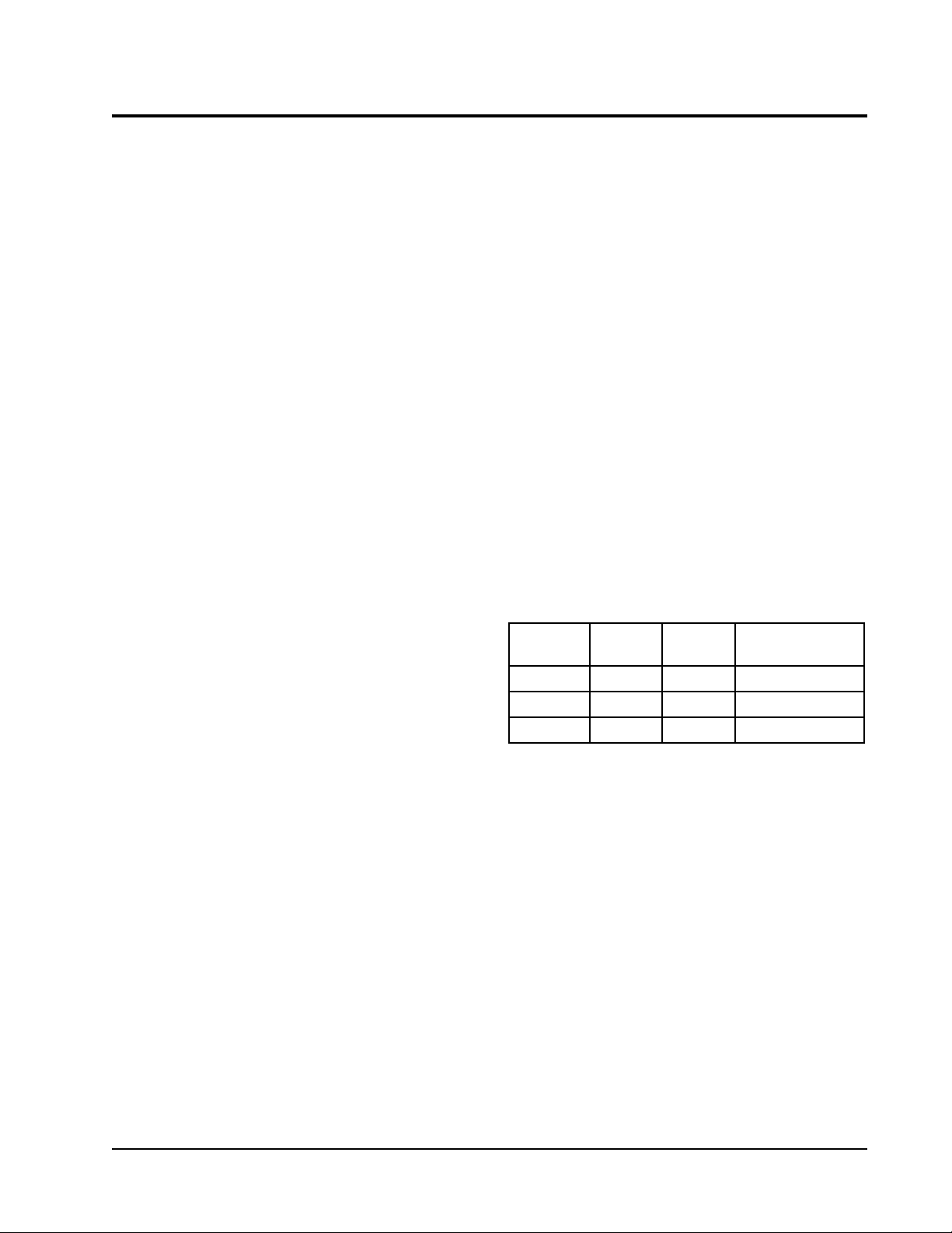
REFRIGERANT CHARGE
The correct system R-22 charge is shown on the unit rating
plate. Optimum unit performance will occur with a
refrigerant charge resulting in a suction line temperature
(6” from compressor) as shown in Table 10.
TABLE 10
FeergeD59
detaR
ledoM
4221HP
0321HP
6321HP
The above suction line temperatures are based upon 80° F
dry bulb/67° F wet bulb (50% RH) temperature and rated
airflow across the evaporator during cooling cycle.
wolfriA
008
0001
0011
DO
erutarepmeT
65-65
65-65
25-05
FeergeD28
DO
erutarepmeT
26-16
06-85
45-25
FAN BLADE SETTINGS
Shown in Figure 12 are the correct fan blade setting
dimensions for proper air delivery across the outdoor coil.
Any service work requiring removal or adjustment in the fan
and/or motor area will require that the dimensions in
Figure 12 be checked and blade adjusted in or out on the
motor shaft accordingly.
3. Turn thermostat blower switch to Auto position. Indoor
blower should stop.
4. Set system switch to heat or cool. Adjust thermostat to
call for heat or cool. The indoor blower, compressor,
and outdoor fan should start.
NOTE: If there is no power to 24 volt transformer, the
compressor and outdoor fan motor will not start
for 5 minutes. This is because of the compressor
short cycle protection.
Manual 2100-344
Page 14
Page 17

TROUBLE SHOOTING GUIDE
motpmySsesuaCelbissoPkcehCottahWriapeRrokcehCotwoH
rotcatnocrosserpmoC
ezigrenetonseod
)gniloocrognitaeh(
noitcetorp
evitcefed
rotomroodtuonaF
nurtonseod
gnitaehrognilooc(
)tsorfedgnirudtpecxe
evitcefed
seodevlavgnisreveR
ezigreneton
)ylnognitaeh(
evitcefed
otniogtonlliwtinU
tsorfed
)ylnognitaeh(
tuoemoctonlliwtinU
tsorfedfo
)ylnognitaeh(
evitcefed
evitcefedrotoMdetrohsroneporofkcehC
evitcefedlioc
.evitcefed
gniriwtiucriclitnoCtinutanoitcennocRrofkcehC
tuokcolrosserpmoCneewtebV42rofkcehC.1
elcyctrohsrosserpmoC
lortnocpmuptaeH
evitcefedrotcatnoCdetrohsroneporofkcehC
evitcefedroticapacrotoM.gnitarroticapackcehC
lortnocpmuptaeH
dionelosevlovgnisreveR
lortnocpmuptaeH
rorosneserutarepmeT
lortnocpmuptaeh
rorosneserutarepmeT
lortnocpmuptaeh
taehrewopottinuroodtuootnoitcennocRnuR
.C-Rneewtebtlov42dna
lortnocpmuptaehnoC-1L
hgihssorcakcehC.2
.hctiwserusserp
C-CCneewtebV42rofkcehC
pmuptaehnoC-Ydna
.lortnoc
elbissoprehtollakcehC
.560-0012launaM.sesuac
.gnidniwlioc
.gnidniwrotom
detrohsroneporofkcehC
.roticapac
noyalernafssorcakcehC
)CN-moC(.lortnocpmuptaeh
detrohsroneporofkcehC
.lioc
C-VRneewtebV42rofkcehC
.C-Bdna
erutarepmettcennocsiD
dnadraobmorfrosnes
pudeepsssorcarepmuj
pmujnesdnaslanimret
esuacdluohssihT.slanimret
ahguorhtogottinueht
enonihtiwelcyctsorfed
.etunim
pudeepsssorcarepmuJ
esuacdluohssihT.slanimret
tsorfedfotuoemocottinueht
.etunimenonihtiw
.lortnocpmup
ffotatsomrehtnrut,C-1LneewtebegatlovonfI.1
.hctiwserusserphgihteserotniaganodna
,tesertonlliwdnaneposihctiwserusserphgihfI.2
.hctiwserusserphgihecalper
pudeepsrepmuj,C-CCneewtebegatlovonfI
dluohsrewopsdnoces01nihtiwdna,lanimret
repmujpudeepsevomeR.C-CCneewtebraeppa
.sdnoces01retfa
.lortnocpmuptaehecalpeR
.rotcatnocecalpeR
.rotomecalpeR
.roticapacecalpeR
.lortnocpmuptaehecalpeR
.liocdionelosecalpeR
.gniriwtiucriclortnockcehC.1
lortnocpmuptaehecalpeR.2
ecalper,elcyctsorfedhguorhtseogtinufI.1
.rosneserutarepmet
ecalper,elcyctsorfedhguorhtogtonseodtinufI.2
.lortnocpmuptaeh
ecalper,elcyctsorfedfotuosemoctinufI.1
.rosneserutarepmet
,elcyctsorfedfotuoemoctonseodtinufI.2
.lortnocpmuptaehecalper
Manual 2100-344
Page 15
Page 18

CHECKING TEMPERATURE SENSOR
CHECK OUT
1. Disconnect temperature sensor from board and from
outdoor coil.
2. Use an ohmmeter and measure the resistance of the
sensor. Also use ohmmeter to check for short or open.
TEMPERATURE F vs RESISTANCE R OF TEMPERATURE SENSOR
FR FR FR FR
0.52-1786910.51046350.55434710.591356
0.42-9900910.61150250.65489610.693836
0.32-5853810.71415050.75745610.799326
0.22-8137710.81820940.85221610.898906
0.12-9821710.91095740.95017510.991695
0.02-7845610.02002640.06013510.0017285
0.91-4099510.12558440.16129410.1017965
0.81-9254510.22455340.26445410.2010755
0.71-5539410.32592240.36771410.3016445
0.61-4734410.42770140.46028310.4016235
0.51-6759310.52898930.56474310.5018025
0.41-6594310.62757830.66731310.5014905
0.31-6050310.72256730.76018210.7012894
0.21-9126210.82385630.86294210.8013784
0.11-9802210.92845530.96381210.9017674
0.01-8018110.03545430.07388110.0113664
0.9-2724110.13475330.17195110.1112654
0.8-5750110.23436230.27703110.2114644
0.7-0107010.33327130.37130110.3117634
0.6-4753010.43048030.47267010.4114724
0.5-0620010.53689920.57105010.5112814
0.4-460790.63751920.67742010.6113904
0.3-189390.73553820.77000010.7116004
0.2-800190.83775720.8706790.8111293
0.1-931880.93328620.9762590.9118383
0.0173580.04290620.0899290.0217573
0.1996280.14383520.1877090.1218763
0.2121080.24696420.2826880.2211063
0.3236770.34030420.3835680.3216253
0.4032570.44483320.4894480.4212543
0.5019270.54857220.580528
0.6076070.64051220.687508
0.7705860.74165120.789687
0.8814660.84989020.886867
0.9993460.94534020.987057
0.01944260.05698910.094337
0.11565060.15473910.195617
0.21547850.25768810.290007
0.31589650.35573810.390486
0.41482550.45898710.493866
3. Check resistance reading to chart of resistance; use
sensor ambient temperature. (Tolerance of part is
± 10%.)
4. If sensor resistance reads very low, then sensor is
shorted and will not allow proper operation of the heat
pump control.
5. If sensor is out of tolerance, shorted, open, or reads very
low ohms then it should be replaced.
Manual 2100-344
Page 16
Page 19

SUCTION AND DISCHARGE TUBE
BRAZING
Compliant Scroll compressors have copper plated steel
suction and discharge tubes. These tubes are far more
rugged and less prone to leaks than copper tubes used on
other compressors. Due to different thermal properties of
steel and copper, brazing procedures may have to be
changed from those commonly used.
• To disconnect: heat joint Areas 2 and 3 slowly and
uniformly until braze material softens and the tube can
be pulled out of suction fitting. (See Figure 10.)
BRAZING DIAGRAM
• To connect:
– Recommended brazing materials: silfos with
minimum 5% silver or silver braze material with
flux.
– Reinsert tube into fitting.
– Heat tube uniformly in Area 1 moving slowly to
Area 2. When joint reaches brazing temperature,
apply brazing material. (See Figure 10.)
– Heat joint uniformly around the circumference to
flow braze material completely around the joint.
– Slowly move torch into Area 3 to draw braze
material into joint. (See Figure 10.)
– Do not overheat joint.
FIGURE 13
MIS-1179
Manual 2100-344
Page 17
Page 20

COOLING
PRESSURE TABLES
TABLE 11
Air T emperature Entering Outdoor Coil Degrees F
riAnruteR
ledoM
4221HP
0321HP
6321HP
erutarepmeTerusserP5708580959001501011511
BD.ged57
BW.ged26
BD.ged08
BW.ged76
BD.ged58
BW.ged27
BD.ged57
BW.ged26
BD.ged08
BW.ged76
BD.ged58
BW.ged27
BD.ged57
BW.ged26
BD.ged08
BW.ged76
BD.ged58
BW.ged27
ediSwoL
ediShgiH
ediSwoL
ediShgiH
ediSwoL
ediShgiH
ediSwoL
ediShgiH
ediSwoL
ediShgiH
ediSwoL
ediShgiH
ediSwoL
ediShgiH
ediSwoL
ediShgiH
ediSwoL
ediShgiH
37
57
67
87
97
08
18
28
191
502
912
432
152
762
582
303
87
08
691
012
18
38
302
712
37
57
802
222
87
08
312
822
18
38
022
632
27
47
112
522
77
97
612
08
28
422
932
18
38
48
88
78
88
522
042
752
472
292
48
68
78
98
09
332
842
662
482
203
67
87
97
97
732
452
072
882
703
18
38
48
58
78
342
062
772
592
513
48
68
78
88
09
252
962
782
503
623
57
77
87
242
852
672
08
28
38
132
842
562
382
38
58
68
752
472
392
97
08
492
413
48
68
203
223
78
98
313
333
113
19
223
18
28
623
88
433
19
643
18
333
78
243
09
453
38
323
98
133
29
343
48
643
09
553
39
763
28
553
88
463
19
773
TABLE 12
HEATING
Air T emperature Entering Outdoor Coil Degrees F
nruteR
ledoM
4221HPged07
0321HPged07
6321HPged07
Low side pressure ± 2 PSIG
High side pressure ± 5 PSIG
T ables are based upon rated CFM (airflow across the evaporator coil and should be found under section titled “Refrigerant Charge” elsewhere
in manual. If there is any doubt as to correct operating charge being in the system, the charge should be removed, system evacuated, and
recharged to serial plate instructions.
pmeTriA
.
erusserP
05 015171025203530454740555
ediSwoL
22
42
72
03
13
33
73
14
54
05
65
ediShgiH
471
281
091
891
102
502
312
122
922
732
542
ediSwoL
12
32
52
82
92
13
43
83
34
84
35
ediShgiH
761
071
471
871
971
281
781
291
791
302
012
ediSwoL
42
52
62
82
82
03
33
73
24
74
35
ediShgiH
491
591
791
102
202
502
112
812
622
532
642
85
26
86
842
352
162
55
95
56
312
712
422
65
06
86
052
752
072
Manual 2100-344
Page 18
Page 21

Wiring Diagram (4098-123) printed
from CAD to get size needed
Manual 2100-344
Page 19
Page 22

Wiring Diagram (4098-124) printed
from CAD to get size needed
Manual 2100-344
Page 20
Page 23

Wiring Diagram (4098-211) printed
from CAD to get size needed
Manual 2100-344
Page 21
 Loading...