

Bard PH11242, PH12241, PH11361, PH1236, PH11422 Installation Instructions Manual
...
INSTALLATION INSTRUCTIONS
SINGLE PACKAGE
HEAT PUMPS
Models:
PH11242 PH12241
PH11301 PH1230
PH11361 PH1236
PH11422 PH1242
PH10481 PH12481
PH1060
Bard Manufacturing Company, Inc.
Bryan, Ohio 43506
Since 1914 . . . Moving ahead, just as planned.
Manual : 2100-354F
Supersedes: 2100-354E
File: Volume II Tab 11
Date: 12-20-06
© Copyright 2004
Manual 2100-354F
Page 1 of 32

CONTENTS
Getting Other Informations and Publications
General Instructions
Important ................................................................ 3
Shipping Damage .................................................... 4
General ................................................................ 4
Field-Installed Heater Packages (Optional) ............. 4
Installation
Location ............................................................... 11
Typical Installations ....................................... 11 & 16
Condensate Drain Trap ......................................... 16
Air Filters .............................................................. 16
Wiring – Main Power ............................................. 17
Wiring – 24V Low Voltage Control Circuit ............. 17
Thermostats ........................................................... 18
Thermostat Indicator Lamps .................................. 19
Emergency Heat Position ...................................... 19
Transformer Taps ................................................... 19
Compressor Cutoff Thermostat and Outdoor
Thermostat Wiring ................................................. 19
Figures
Figure 1 Unit Dimensional Drawing ..................... 10
Figure 2 Slab Mounting at Ground Level ............ 12
Figure 3 Airflow and Service Access
Clearances ............................................ 12
Figure 4 Roof Top Application ............................. 13
Figure 5 Elevated Mounting Platforms ................ 13
Figure 6 Prefabricated Rood Curb
Specifications ........................................ 14
Figure 7 Field Fabricated Curbing ....................... 15
Figure 8 Condensate Drain Trap ......................... 16
Figure 9 Low Voltage Wiring ............................... 17
Figure 10 Unit 24V Terminal Board (5–10 KW)..... 19
Figure 11 Unit 24V Terminal Board (15–20 KW) ... 20
Figure 12 Heat Pump Control Board ..................... 22
Figure 13 Fan Blade Setting ................................. 25
Figure 14 Brazing Diagram ................................... 26
Start Up and Operation
Three Phase Scroll Compressor Start Up
Information ............................................................. 21
Sequence of Operation .......................................... 21
Defrost Cycle ......................................................... 22
Troubleshooting
Solid State Heat Pump Control
Troubleshooting Procedure ................................... 23
Troubleshooting Guide .......................................... 23
Checking Temperature Sensor Check Out ............ 24
Temperature vs. Resistance of
Temperature Sensor Chart .................................... 24
Service
Service Hints ......................................................... 25
Pressure Service Ports .......................................... 25
Refrigerant Charge ................................................ 25
Fan Blade Settings ................................................ 25
Suction and Discharge Tube Brazing .................... 26
Troubleshooting GE ECM™ Blower Motors ... 27 & 28
Pressure Tables ................................................ 29-32
Tables
Table 1 Rated CFM and ESP .............................. 4
Table 2 Electrical Data ......................................... 5
Table 2A Electrical Data ......................................... 6
Table 2B Electrical Data ......................................... 7
Table 3 Optional Field Installed Heater
Packages ................................................ 8
Table 4 Electric Heater Table ............................... 9
Table 5 Dimensions of Unit................................ 10
Table 6 Roof Curb Dimensions .......................... 14
Table 7 Dimension “X” for Field Fab Curbing .... 15
Table 8 Filters Required & Size ......................... 16
Table 9 Heat Pump Thermostats ....................... 18
Table 10 Thermostat Wire Size ........................... 18
Table 11 Compressor Cutoff Thermostat
Wiring (5 - 10 KW) ............................... 20
Table 12 Compressor Cutoff Thermostat
Wiring (15 - 20 KW) ............................. 20
Table 13 Refrigerant Charge ............................... 25
Table 14 Fan Blade Setting Dimensions .............. 25
Table 15 Indoor Blower Performance .................. 26
Table 16 Pressure Table - Cooling ....................... 29
Table 17 Pressure Table - Heating ...................... 29
Table 18 Pressure Table - Cooling ....................... 30
Table 19 Pressure Table - Heating ...................... 30
Table 20 Pressure Table - Cooling ....................... 31
Table 21 Pressure Table - Heating ...................... 31
Table 22 Pressure Table - Cooling ....................... 32
Table 23 Pressure Table - Heating ...................... 32
Manual 2100-354F
Page 2 of 32

Getting Other Information and Publications
These publications can help you install the air conditioner
or heat pump. You can usually find these at your local
library or purchase them directly from the publisher. Be
sure to consult current edition of each standard.
National Electrical Code ........................... ANSI/NFPA 70
Standard for the Installation ................... ANSI/NFPA 90A
of Air Conditioning and Ventilating Systems
Standard for Warm Air .......................... ANSI/NFPA 90B
Heating and Air Conditioning Systems
Load Calculation for ................................ ACCA Manual J
Residential Winter and Summer Air Conditioning
Duct Design for Residential ................... ACCA Manual D
Winter and Summer Air Conditioning and Equipment
Selection
FOR MORE INFORMATION, CONTACT
THESE PUBLISHERS:
ACCA Air Conditioning Contractors of America
1712 New Hampshire Ave. N.W.
Washington, DC 20009
Telephone: (202) 483-9370
Fax: (202) 234-4721
ANSI American National Standards Institute
11 West Street, 13th Floor
New York, NY 10036
Telephone: (212) 642-4900
Fax: (212) 302-1286
ASHRAE American Society of Heating Refrigerating,
and Air Conditioning Engineers, Inc.
1791 Tullie Circle, N.E.
Atlanta, GA 30329-2305
Telephone: (404) 636-8400
Fax: (404) 321-5478
NFPA National Fire Protection Association
Batterymarch Park
P.O. Box 9101
Quincy, MA 02269-9901
Telephone: (800) 344-3555
Fax: (617) 984-7057
Manual 2100-354F
Page 3 of 32
GENERAL INSTRUCTIONS
IMPORTANT
The equipment covered in this manual is to be installed by
trained, experienced service and installation technicians.
Any heat pump is more critical of proper operating charge
and an adequate duct system than a straight air conditioning
unit. All duct work, supply and return ducts, must be
properly sized for the design air flow requirement of the
equipment. ACCA is an excellent guide to proper sizing.
All duct work or portions thereof not in the conditioned
space should be properly insulated in order to both
conserve energy and prevent condensation or moisture
damage.
SHIPPING DAMAGE
Upon receipt of equipment, the carton should be checked
for external signs of shipping damage. If damage is found,
the receiving party must contact the last carrier
immediately, preferably in writing, requesting inspection
by the carrier’s agent.
GENERAL
The refrigerant system is completely assembled and
charged. All internal wiring is complete.
The unit is designed for use with or without duct work.
Flanges are provided for attaching the supply and return
ducts.
These instructions and any instructions packaged with any
separate equipment required to make up the entire heat
pump system should be carefully read before beginning the
installation. Note particularly “Starting Procedure” and any
tags and/or labels attached to the equipment.
While these instructions are intended as a general
recommended guide, they do not supersede any national
and/or local codes in any way. Authorities having
jurisdiction should be consulted before the installation is
made.
FIELD INSTALLED HEATER PACKAGES
(OPTIONAL)
These packaged heat pumps are manufactured without
supplementary electric heaters. Supplementary heaters are
available for simple, fast field installation.
A separate power circuit is required for the supplementary
heaters.
IMPORTANT: Refer to Table 1 when designing duct work
for maximum available static pressure with heater installed.
Refer to electrical data shown in Tables 3 and 4 for proper
application information on all available heater
combinations and what units they can be used with. It also
shows the applicable circuit ampacities, fuse size, and wire
size for each heater combination.
These instructions explain the recommended method to
install the air cooled self-contained unit and the electrical
wiring connections to the unit.
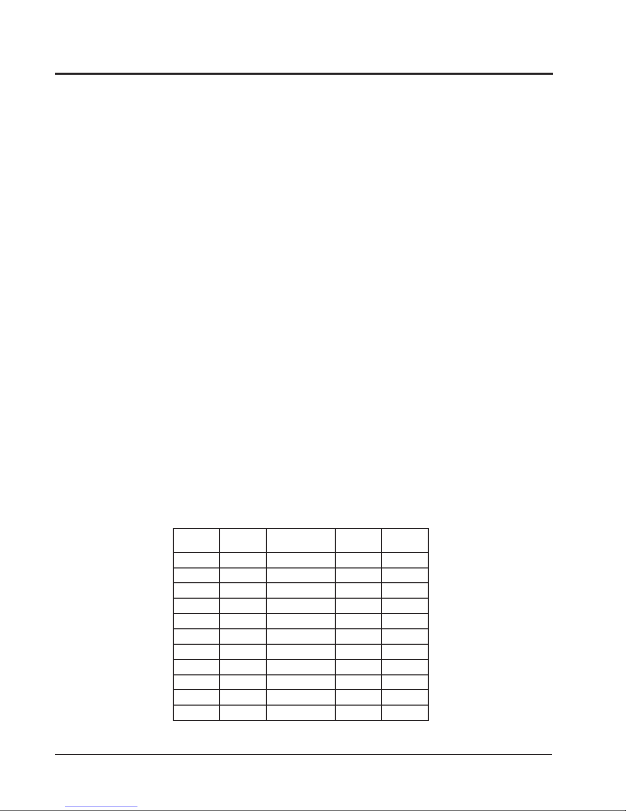
RATED CFM AND EXTERNAL STATIC PRESSURE (ESP)
ledoM
24211HP008088-08602.005.0
14221HP008
10311HP00010011-57703.004.0
0321HP0001
16311HP00010121-57702.004.0
6321HP0001
22411HP00410451-062102.053.0
2421HP0041
18401HP05510071-004104.005.0
18421HP0551
0601HP00710781-035102.005.0
detaR
MFC
NOTE: Motor will adjust to deliver rated airflow.
TABLE 1
1etoN
1etoN
1etoN
1etoN
1etoN
dednemmoceR
egnaRwolfriA
detaR
PSE
01.005.0
51.005.0
51.005.0
51.005.0
02.005.0
mumixaM
PSE
Manual 2100-354F
Page 4 of 32

TABLE 2
ELECTRICAL DATA
ledoM24211HP10311HP16311HPB-16311HPC-16311HP22411HP
gnitaRcirtcelE
AtkC-zH06
1-06-802/0321-06-802/0321-06-802/0323-06-802/0323-06-0641-06-802/032
egnaRegatoVgnitarepO352-791352-791352-791352-781605-414352-791
yticapmAtiucriCmuminiM711252812123
CSCB115.3181116
*eziSeriWdleiF0101801418
eziSeriWdnuorG010101014101
**.xaM-esuFyaleD520304525105
802-302-spmAtinUlatoT9.41/9.312.71/7.517.02/9.818.31/2.319.62.42/8.22
AtiucriC-rosserpmoC
epyTrosserpmoCllorcSllorcSllorcSllorcSllorcSllorcS
stloV802/032802/032802/032802/032064802/032
spmAdaoLdetaR11/0131/5.115.61/7.416.9/0.97.45.81/1.71
spmArotoRkcoL45/455.27/5.2788/8877/7793401/401
resnednoCdnarotoMnaF
MPR/PH-rotoMnaF0901-5/15701-5/15701-5/15701-5/15701-5/1528-3/1
spmArotoMnaF2.16.16.16.18.05.2
MFC/aiDnaF0561/"020002/"020002/"020002/"020002/"020592/"42
rotaropavEdnarotoM
MPR/PH-rotoMrewolB5701-3/15701-3/15701-3/15701-3/15701-3/15701-2/1
spmA-rotoMrewolB1.26.26.26.24.17.3
PSE&gnilooCMFC02.0@00803.0@001102.0@001102.0@001102.0@001102.0@0041
).zo22-R(egrahC8839686868121
)sdnuop(thgieWgnippihS563563563563563534
5.81
* 75 degree C copper wire
** Maximum time delay fuse of HACR type circuit breaker
Manual 2100-354F
Page 5 of 32
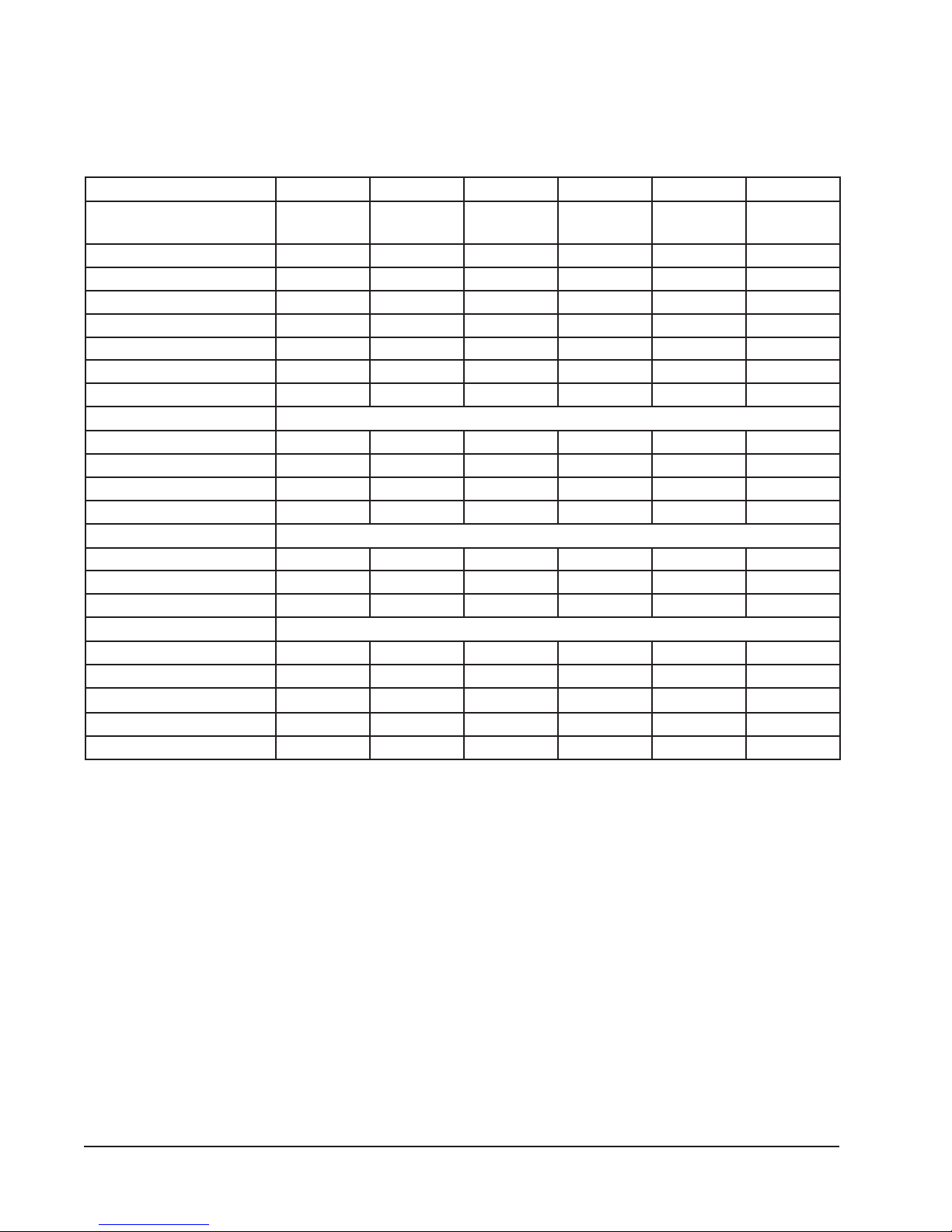
TABLE 2A
ELECTRICAL DATA
ledoM18401HPB-18401HPC-18401HP0601HPB-0601HPC-0601HP
gnitaRcirtcelE
AtkC-zH06
1-06-802/0323-06-802/0323-06-0641-06-802/0323-06-802/0323-06-064
egnaRegatoVgnitarepO352-791352-781605-414352-791352-781605-414
yticapmAtiucriCmuminiM435221349241
CSCB5.127.411.792819
*eziSeriWdleiF8
8218821
eziSeriWdnuorG010101010121
**.xaM-esuFyaleD055351065402
802-302-spmAtinUlatoT2.12/2.527.91/3.819
5.23/3.038.22/3.1211
AtiucriC-rosserpmoC
epyTrosserpmoCllorcSllorcSllorcSllorcSllorcSllorcS
stloV802/032802/032064802/032802/032064
spmAdaoLdetaR5.12/5.910.41/6.212.68.62/6.421.71/6.512.8
spmArotoRkcoL731/73119/1905841/841731/73126
resnednoCdnarotoMnaF
MPR/PH-rotoMnaF058-3/1058-3/1058-3/1058-3/1058-3/1058-3/1
spmArotoMnaF5.25.22.15.25.22.1
MFC/aiDnaF0003/"420003/"420003/"420003/"420003/"420003/"42
rotaropavEdnarotoM
MPR/PH-rotoMrewolB5701-2/15701-2/15701-2/15701-2/15701-2/15701-2/1
spmA-rotoMrewolB7.37.38.17.37.38.1
PSE&gnilooCMFC0551
@
04.00551
@
04.00551
@
04.00071
@
02.00071
@
02.00071
@
02.0
).zo22-R(egrahC521521521761761761
)sdnuop(thgieWgnippihS054054054054054054
* 75 degree C copper wire
** Maximum time delay fuse of HACR type circuit breaker
Manual 2100-354F
Page 6 of 32

TABLE 2B
ELECTRICAL DATA
ledoM14221HP0321HP6321HPB-6321HP2421HP18421HPB-18421HP
gnitaRcirtcelE
AtkC-zH06
egnaRegatoVgnitarepO352-791352-791352-791352-781352-791352-791352-781
yticapmAtiucriCmuminiM7112629103334.52
CSCB5.015.315.619.01815.027.41
*eziSeriWdleiF21010121018
eziSeriWdnuorG01010101010101
**.xaM-esuFyaleD52030452540553
802-302-spmAtinUlatoT9.31/9.211.71/6.512.12/4.916.51/7.415.42/5.325.72/5.523.02/0.91
AtiucriC-rosserpmoC
epyTrosserpmoCllorcSllorcSllorcSllorcSllorcSllorcSllorcS
stloV802/032802/032802/032802/032802/032802/032802/032
spmAdaoLdetaR5.01/5.90.31/5.115.61/7.419.01/017.71/7.615.02/5.813.31/0.21
spmArotoRkcoL45/455.27/5.2788/8877/77401/401731/73119/19
resnednoCdnarotoMnaF
MPR/PH-rotoMnaF0901-5/15701-5/15701-5/15701-5/1528-3/1528-3/1528-3/1
spmArotoMnaF2.14.14.14.15.25.25.2
MFC/aiDnaF0561/"020002/"020002/"020002/"020003/"420003/"420003/"42
rotaropavEdnarotoM
MPR/PH-rotoMrewolBelbairaV3/1elbairaV2/1elbairaV2/1elbairaV2/1elbairaV4/3elbairaV4/3elbairaV4/3
spmA-rotoMrewolB1.27.23.33.33.45.45.4
PSE&gnilooCMFC01.0@00851.0@000151.0@000151.0@000102.0@004102.0@055102.0@0551
).zo22-R(egrahC1999121121331321321
)sdnuop(thgieWgnippihS023533543543024044044
1-06-802/0321-06-802/0321-06-802/0323-06-802/0321-06-802/0321-06-802/0323-06-802/032
8
* 75 degree C copper wire
** Maximum time delay fuse of HACR type circuit breaker
Manual 2100-354F
Page 7 of 32
tfelneebsah
nmulocsihT
yllanoitnetni
knalb
TABLE 3
AN SAA ANAN
AN ASA ANS3
OPTIONAL FIELD INSTALLED HEATER PACKAGES
ANSAN SAA ANAN
ONLY TO BE USED WITH THE HEAT PUMP MODELS INDICATED
dnastloV
esahP24211HP14221HP10311HP0321HP16311HPB-16311HPC-16311HP6321HPB-6321HP
50A-CP3HE1-802/042ANSANSANANANSAN
01A-CP3HE1-802/042ANSANANANANANANAN
80A-BP3HE1-802/042SANSAN SAA ANAN
50A-BP3HE1-802/042S
01A-BP3HE1-802/042ANANS1 SS1 A 1 A 1 SAN
egakcaP
ledoM
retaeH
51A-BP3HE1-802/042ANANS
51A-CP3HE1-802/042ANANANS2 ANANANS2 AN
90B-BP3HE3-802/042ANANA1 ANA1 S 1 A 1 ANS
90C-BP3HE3-084ANANA1 ANA1 A 1 S 1 ANAN
51B-BP3HE3-802/042ANANA
51C-BP3HE3-084ANANAAN AAS ANAN
Max. KW that can operate with Heat Pump on.
Max. KW that can operate with Heat Pump on is 10 KW. 15 KW will operate during
emergency heat.
Max. KW that can operate with Heat Pump on is 9KW. 15 KW will operate during
emergency heat
1
2
3
ASA ANS3 AS A
S2 SAAS2 ANSAA
SSSAAS ANSAA
dnastloV
esahP22411HP2421HP18401HPB-18401HPC-18401HP18421HPB-18421HP0601HPB-0601HPC-0601HP
90C-CP5HE3-084ANANA1 A 1 S 1 ANANA1 A 1 S 1
90B-BP5HE3-802/042ANANA1 S 1 A 1 ANSA1 S 1 A 1
51B-BP5HE3-802/042ANAN
81B-BP5HE3-802/042ANAN ASA ANANASA
50A-BP5HE1-802/042
egakcaP
ledoM
retaeH
02A-BP5HE1-802/042ANAN SAA ANANSAA
01A-BP5HE1-802/042S1 SS1 A 1 A 1 SANS1 A 1 A 1
51A-BP5HE1-802/042S
81C-CP5HE3-084ANAN AAS ANANAAS
Manual 2100-354F
Page 8 of 32
S=Standard application – heater voltage and phase same as basic unit.
A=Alternate application – heater voltage and phase different from basic unit.
NA=Not approved.
eziSeriW
dnuorG
rewoP
gniriW
noitcetorP
tnerruC
010101801
01/01
01/01
8/6
52/03
05/0607/08
04/54
3
dleiF
2
revO.xaM
BtiucriC
1
yticapmA
tiucriC
.niM
.oN
retaeH
32/62
stiucriC
dleiF
1111111
lanretnI
esuF
64/35
63/24
01
01/01
8/6
4/4
52/03
05/06
86/97
32/62
84/35
06/03
01
8
4/4
07/08
86/97
01
8
01/01
8/6
4/4
52/03
05/06
07/08
32/62
86/97
64/35
111
06/03
06/03
01
01
6
01/01
3/2
001/011
52/03
19/401
42/82
1
1
010101
01/01
8/8
04/05
93/64
1
8/8
52/03
04/05
42/82
93/64
111
41
01
41
01
01
8/6
41
01
41
01
01
05/
51
06
74/55
51
1
51
52
32
1
52
51
32
111
03
82
06/06
1.81/8.02
retaeH
spmA
008,21
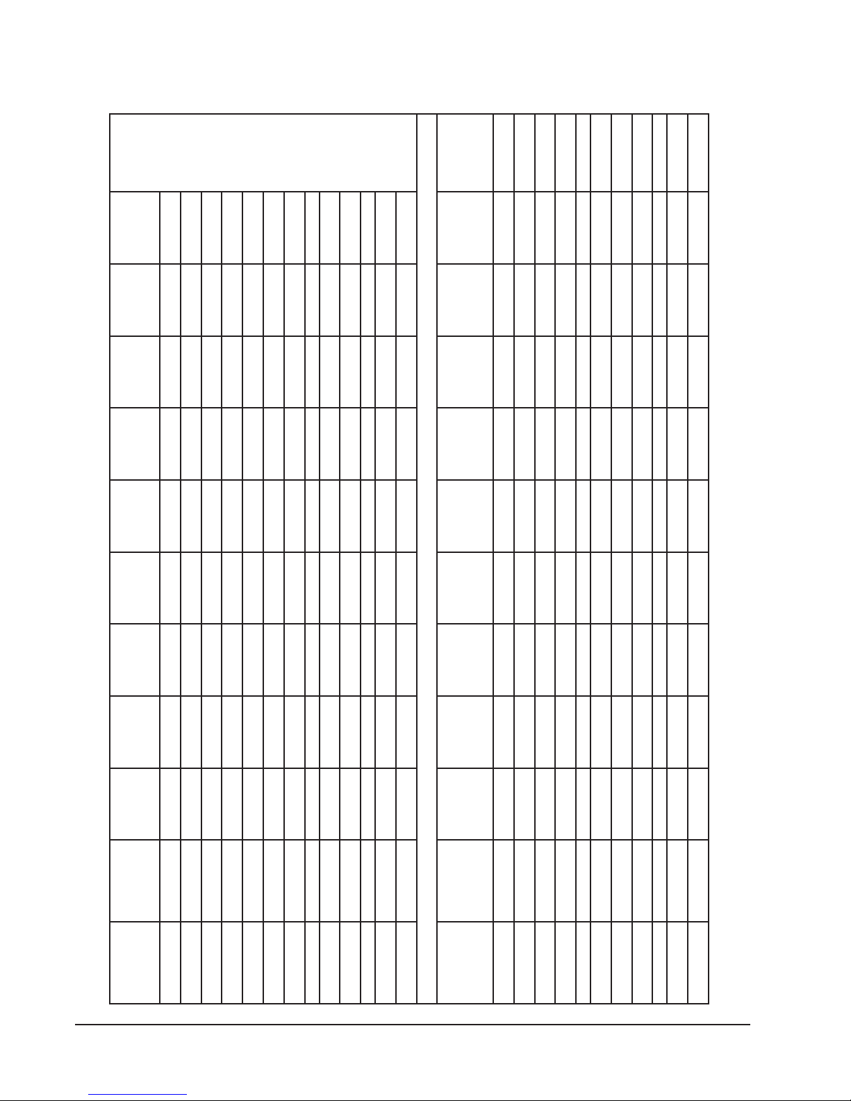
TABLE 4
V802/042
&WKretaeH
stloV802
@yticapaC
57.3
OPTIONAL FIELD INSTALLED ELECTRIC HEATER TABLE
&WKretaeH
stloV042
@yticapaC
001,71
1.45/5.26
1.81/8.02
1.45/5.26
8.82/3.33
2.63/6.14
005,02
000,62
2.63/6.14
008,21
004,83
000,62
1.81/8.02
008,21
004,83
1.27/2.38
1.45/5.26
2.63/6.14
000,62
004,83
00
2,15
00.6
05.7
52.11
57.3
05.7
52.11
57.3
05.7
52.11
00.51
003,72
001,71
002,15
001,43
001,4
001,71
002,15
002,86
002,15
001,43
3
01
WKHUTBWKHUTB
5
1-802/042
sesahP&
stloVtinU
51501
8
1-802/042
1-802/042
1-802/042
51
1-802/042
1-802/042
1-802/042
01
51
5
1-80
02
1-802/042
1-802/042
1-802/042
2/042
.gkPretaeH
50A-BP3HE
80A-BP3HE
.oNledoM
80A-CP3HE
01A-CP3HE
01A-BP3HE
51A-BP3HE
51A-CP3HE
50A-BP5HE
02A-BP5HE
01A-BP5HE
51A-BP5HE
2.13/2.63
7.81/7.12
000,32
004,83
2.13/2.63
7.81/7.12
5.73/4.34
8.01
0.81
8.01
0.81
7.12
000,32
004,83
002,82
001,64
002,82
000,74
00
000,74
4,65
52.11
57.6
007,03
002,15
51
9
3-802/042
3-802/042
90B-BP3HE
51B-BP3HE
05.31
52.11
57.3
007,03
002,15
004,16
51
81
9
3-802/042
3-802/042
3-802/042
90B-BP5HE
51B-BP5HE
81B-BP5HE
77.31
62.8
007,03
002,15
51
9
3-084
3-084
90C-BP3HE
51C-BP3HE
77.31
35.61
62.8
007,03
002,15
004,16
51
81
9
3-084
3-084
3-084
90C-BP5HE
51C-BP5HE
81C-BP5HE
Time delay fuses of HACR type circuit breakers must be used for 60 and smaller sizes. Standard fuses or circuit breakers are suitable for sizes 70 and
larger. 480V circuit breakers are not HACR type.
Based on wire suitable for 75 degree C. Other wiring materials must be rated for marked Minimum Circuit Ampacity or greater.3Based upon Table 250-95 of N.E.C. 1993. See electric data for basic heat pump for Circuit A wiring specification requirements.
1
2
accordance with the national Electrical Code and all existing local codes.
NOTE: While this electrical data is presented as a guide, it is important to electrically connect properly sized fuses and conductor wires in
Manual 2100-354F
Page 9 of 32
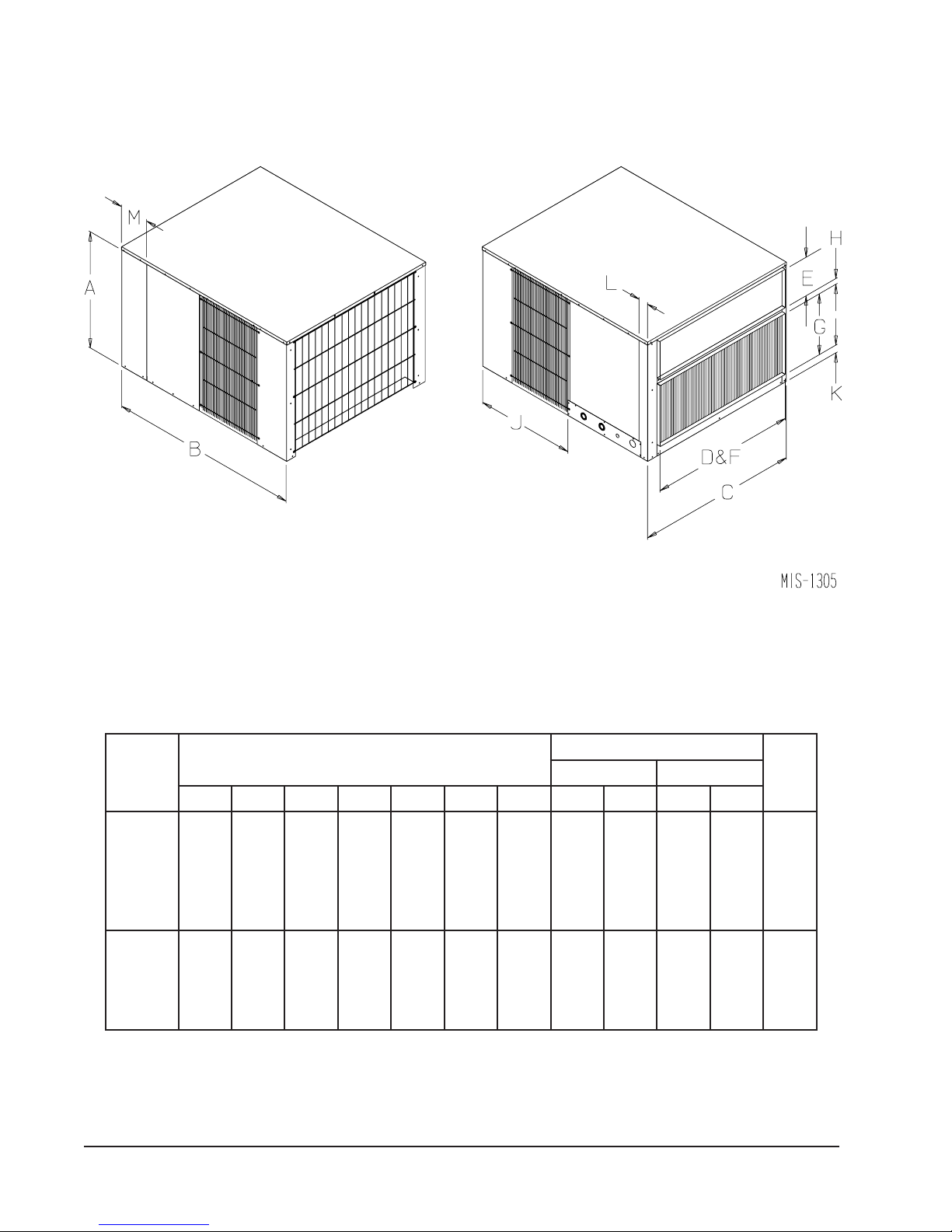
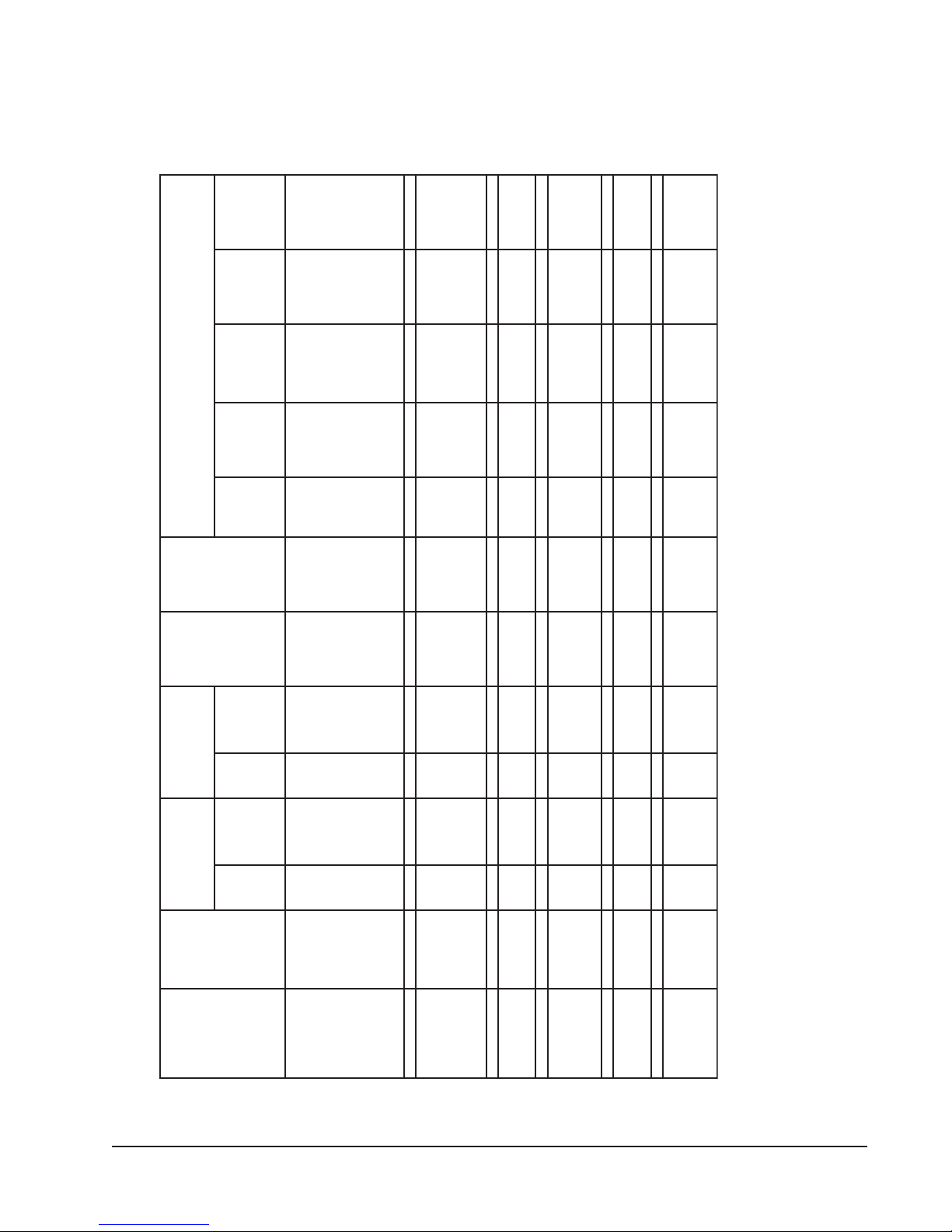
FIGURE 1
UNIT DIMENSIONAL DRAWING
TABLE 5
DIMENSIONS OF UNIT
)sehcnI(gninepOtcuD
ledoM
.oN
ABCJKLMDEFG
4211HP
4221HP
0311HP
0321HP
6311HP
6321HP
2411HP
2421HP
8411HP
8421HP
0601HP
4/1-4261/3-848/1-838/1-628/1-261/961/933633418/7
4/1-130524623
)sehcnI(snoisnemiDtenibaClanimoN
4/3-261/9-7830183618/3-1
egrahcsiDriAnruteR
H
Manual 2100-354F
Page 10 of 32
 Loading...