

Bard PH11242, PH12241, PH11301, PH1230, PH11361 Installation Instructions Manual
...
INSTALLATION INSTRUCTIONS
SINGLE PACKAGE
HEAT PUMPS
Models:
PH11242 PH12241
PH11301 PH1230
PH11361 PH1236
PH11422 PH1242
PH10481 PH11481
PH1060
Bard Manufacturing Company
Bryan, Ohio 43506
Since 1914 . . . Moving ahead, just as
planned.
Manual : 2100-354B
Supersedes: 2100-354A
File: Volume II Tab 11
Date: 03-19-03
© Copyright 2003

CONTENTS
Getting Other Informations and Publications
General Instructions
Important ................................................................ 2
Shipping Damage .................................................... 2
General ................................................................ 2
Field-Installed Heater Packages (Optional) ............. 2
Installation
Location ................................................................ 9
Typical Installations ................................................. 9
Condensate Drain Trap ......................................... 14
Air Filters .............................................................. 14
Wiring – Main Power ............................................. 15
Wiring – 24V Low Voltage Control Circuit ............. 15
Thermostats........................................................... 16
Thermostat Indicator Lamps .................................. 17
Emergency Heat Position ...................................... 17
Transformer Taps................................................... 17
Compressor Cutoff Thermostat and Outdoor
Thermostat Wiring ................................................. 17
Figures
Figure 1 Unit Dimensional Drawing....................... 8
Figure 2 Slab Mounting at Ground Level ............ 10
Figure 3 Airflow and Service Access
Clearances............................................ 10
Figure 4 Roof Top Application..............................11
Figure 5 Elevated Mounting Platforms .................11
Figure 6 Prefabricated Rood Curb
Specifications........................................ 12
Figure 7 Field Fabricated Curbing....................... 13
Figure 8 Condensate Drain Trap......................... 14
Figure 9 Low Voltage Wiring ............................... 15
Figure 10 Unit 24V Terminal Board (5–10 KW)..... 17
Figure 11 Unit 24V Terminal Board (15–20 KW)... 18
Figure 12 Heat Pump Control Board..................... 20
Figure 13 Fan Blade Setting ................................. 23
Figure 14 Brazing Diagram ................................... 24
Start Up and Operation
Three Phase Scroll Compressor Start Up
Information............................................................. 19
Sequence of Operation.......................................... 19
Defrost Cycle ......................................................... 20
Troubleshooting
Solid State Heat Pump Control
Troubleshooting Procedure ................................... 21
Troubleshooting Guide .......................................... 21
Checking Temperature Sensor Check Out ............ 22
Temperature vs. Resistance of
Temperature Sensor Chart .................................... 22
Service
Service Hints ......................................................... 23
Pressure Service Ports .......................................... 23
Refrigerant Charge ................................................ 23
Fan Blade Settings ................................................ 23
Suction and Discharge Tube Brazing .................... 24
Troubleshooting ECM Blower Motors ............ 25 & 26
Pressure Tables ................................................ 27-30
Tables
Table 1 Rated CFM and ESP .............................. 2
Table 2 Electrical Data......................................... 3
Table 2A Electrical Data......................................... 4
Table 2B Electrical Data......................................... 5
Table 3 Optional Field Installed Heater
Packages ................................................ 6
Table 4 Electric Heater Table............................... 7
Table 5 Dimensions of Unit.................................. 8
Table 6 Roof Curb Dimensions.......................... 12
Table 7 Thermostat Wire Size ........................... 13
Table 8 Wall Thermostat and Subbase
Combinations .......................................... 9
Table 9 Required Filters..................................... 14
Table 10 Thermostat Wire Size ........................... 16
Table 11 Compressor Cutoff Thermostat
Wiring (5 - 10 KW) ............................... 18
Table 12 Compressor Cutoff Thermostat
Wiring (15 - 20 KW) ............................. 18
Table 13 Refrigerant Charge ............................... 23
Table 14 Fan Blade Setting Dimensions.............. 23
Table 15 Indoor Blower Performance .................. 24
Table 16 Pressure Table - Cooling....................... 27
Table 17 Pressure Table - Heating ...................... 27
Table 18 Pressure Table - Cooling....................... 28
Table 19 Pressure Table - Heating ...................... 28
Table 20 Pressure Table - Cooling....................... 29
Table 21 Pressure Table - Heating ...................... 29
Table 22 Pressure Table - Cooling....................... 30
Table 23 Pressure Table - Heating ...................... 30

Getting Other Information and Publications
These publications can help you install the air conditioner
or heat pump. You can usually find these at your local
library or purchase them directly from the publisher. Be
sure to consult current edition of each standard.
National Electrical Code...........................ANSI/NFPA 70
Standard for the Installation .................. ANSI/NFPA 90A
of Air Conditioning and
Ventilating Systems
Standard for Warm Air .......................... ANSI/NFPA 90B
Heating and Air
Conditioning Systems
Load Calculation for ............................... ACCA Manual J
Residential Winter and
Summer Air Conditioning
Duct Design for Residential................... ACCA Manual D
Winter and Summer Air Conditioning
and Equipment Selection
FOR MORE INFORMATION, CONTACT
THESE PUBLISHERS:
ACCA Air Conditioning Contractors of America
1712 New Hampshire Ave. N.W.
Washington, DC 20009
Telephone: (202) 483-9370
Fax: (202) 234-4721
ANSI American National Standards Institute
11 West Street, 13th Floor
New York, NY 10036
Telephone: (212) 642-4900
Fax: (212) 302-1286
ASHRAE American Society of Heating Refrigerating,
and Air Conditioning Engineers, Inc.
1791 Tullie Circle, N.E.
Atlanta, GA 30329-2305
Telephone: (404) 636-8400
Fax: (404) 321-5478
NFPA National Fire Protection Association
Batterymarch Park
P.O. Box 9101
Quincy, MA 02269-9901
Telephone: (800) 344-3555
Fax: (617) 984-7057
Manual 2100-354
Page 1
GENERAL INSTRUCTIONS
IMPORTANT
The equipment covered in this manual is to be installed by
trained, experienced service and installation technicians.
Any heat pump is more critical of proper operating charge
and an adequate duct system than a straight air
conditioning unit. All duct work, supply and return ducts,
must be properly sized for the design air flow requirement
of the equipment. ACCA is an excellent guide to proper
sizing. All duct work or portions thereof not in the
conditioned space should be properly insulated in order to
both conserve energy and prevent condensation or
moisture damage.
SHIPPING DAMAGE
Upon receipt of equipment, the carton should be checked
for external signs of shipping damage. If damage is found,
the receiving party must contact the last carrier
immediately, preferably in writing, requesting inspection
by the carrier’s agent.
GENERAL
The refrigerant system is completely assembled and
charged. All internal wiring is complete.
The unit is designed for use with or without duct work.
Flanges are provided for attaching the supply and return
ducts.
These instructions and any instructions packaged with any
separate equipment required to make up the entire heat
pump system should be carefully read before beginning the
installation. Note particularly “Starting Procedure” and
any tags and/or labels attached to the equipment.
While these instructions are intended as a general
recommended guide, they do not supersede any national
and/or local codes in any way. Authorities having
jurisdiction should be consulted before the installation is
made.
FIELD INSTALLED HEATER PACKAGES
(OPTIONAL)
These packaged heat pumps are manufactured without
supplementary electric heaters. Supplementary heaters are
available for simple, fast field installation.
A separate power circuit is required for the supplementary
heaters.
IMPORTANT: Refer to Table 1 when designing duct
work for maximum available static pressure with heater
installed.
Refer to electrical data shown in Tables 3 and 4 for proper
application information on all available heater
combinations and what units they can be used with. It also
shows the applicable circuit ampacities, fuse size, and wire
size for each heater combination.
These instructions explain the recommended method to
install the air cooled self-contained unit and the electrical
wiring connections to the unit.
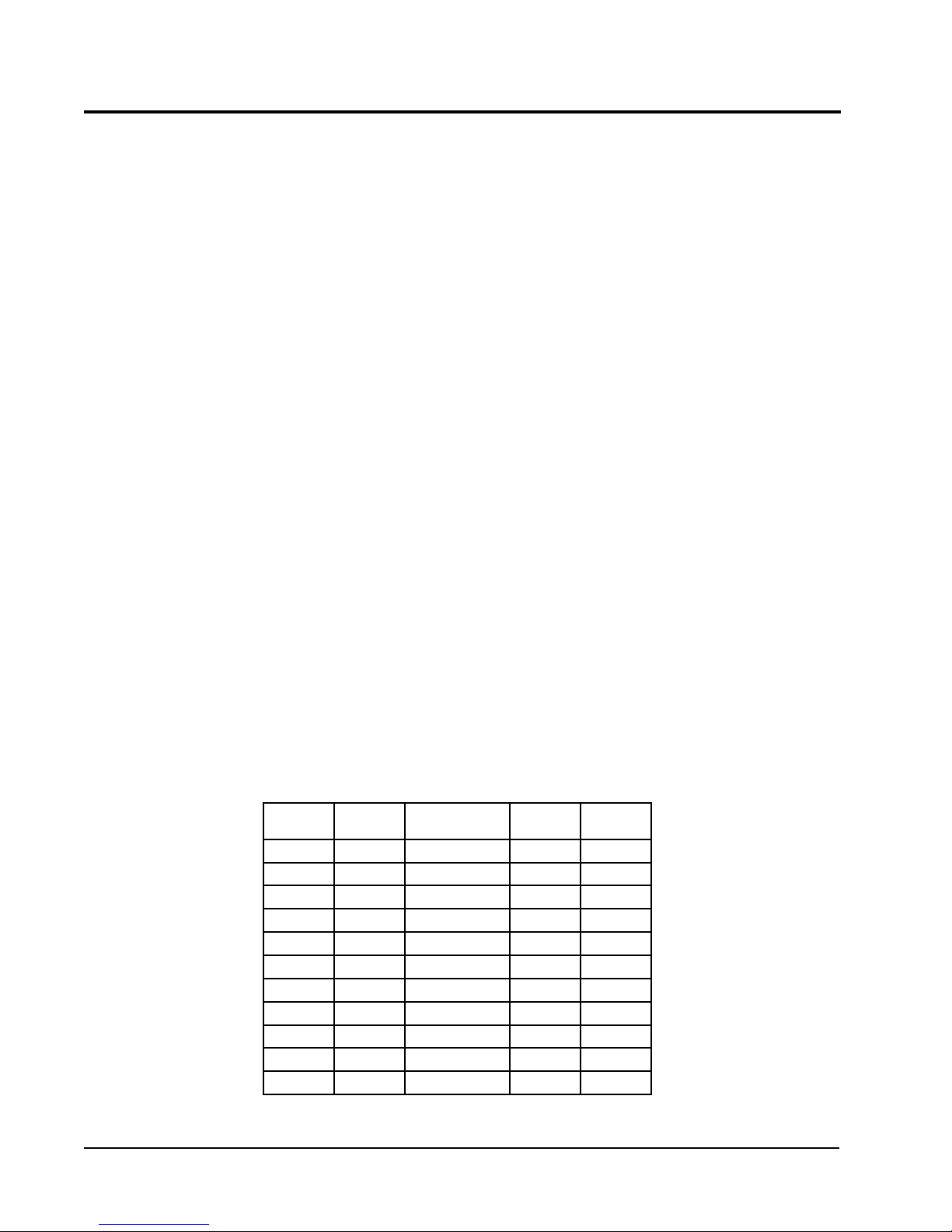
RATED CFM AND EXTERNAL STATIC PRESSURE (ESP)
ledoM
24211HP008088-08602.005.0
14221HP008
10311HP00010011-57703.004.0
0321HP0001
16311HP00010121-57702.004.0
6321HP0001
22411HP00410451-062102.053.0
2421HP0041
18401HP05510071-004104.005.0
18421HP0551
0601HP00710781-035102.005.0
detaR
MFC
NOTE: Motor will adjust to deliver rated airflow.
TABLE 1
1etoN
1etoN
1etoN
1etoN
1etoN
dednemmoceR
egnaRwolfriA
detaR
PSE
01.005.0
51.005.0
51.005.0
51.005.0
02.005.0
mumixaM
PSE
Manual 2100-354
Page 2

TABLE 2
ELECTRICAL DATA
ledoM24211HP10311HP16311HPB-16311HPC-16311HP22411HP
gnitaRcirtcelE
AtkC-zH06
1-06-802/0321-06-802/0321-06-802/0323-06-802/0323-06-0641-06-802/032
egnaRegatoVgnitarepO352-791352-791352-791352-781605-414352-791
yticapmAtiucriCmuminiM711252812192
CSCB115.3181116 5.81
*eziSeriWdleiF0101801418
eziSeriWdnuorG010101014101
**.xaM-esuFyaleD520304525105
802-302-spmAtinUlatoT9.41/9.312.71/7.517.02/9.818.31/2.319.62.42/8.22
AtiucriC-rosserpmoC
epyTrosserpmoCllorcSllorcSllorcSllorcSllorcSllorcS
stloV802/032802/032802/032802/032064802/032
spmAdaoLdetaR11/0131/5.115.61/7.416.9/0.97.45.81/1.71
spmAretoRkcoL45/455.27/5.2788/8877/7793401/401
resnednoCdnarotoMnaF
MPR/PH-rotoMnaF0901-5/15701-5/15701-5/15701-5/15701-5/1528-3/1
spmArotoMnaF8.16.16.16.18.05.2
MFC/aiDnaF0561/"020002/"020002/"020002/"020002/"020592/"42
rotaropavEdnarotoM
MPR/PH-rotoMrewolB5701-3/15701-3/15701-3/15701-3/15701-3/15701-2/1
spmA-rotoMrewolB1.26.26.26.24.12.3
PSE&gnilooCMFC02.0@00803.0@001102.0@001102.0@001102.0@001102.0@0041
).zo22R(egrahC8839686868121
)sdnuop(thgieWgnippihS563563563563563534
* 75 degree C copper wire
** Maximum time delay fuse of HACR type circuit breaker
Manual 2100-354
Page 3

TABLE 2A
ELECTRICAL DATA
ledoM18401HPB-18401HPC-18401HP0601HPB-0601HPC-0601HP
gnitaRcirtcelE
AtkC-zH06
1-06-802/0323-06-802/0323-06-0641-06-802/0323-06-802/0323-06-064
egnaRegatoVgnitarepO352-791352-781605-414352-791352-781605-414
yticapmAtiucriCmuminiM334221248241
CSCB5.127.411.792819
*eziSeriWdleiF88218821
eziSeriWdnuorG010101010121
**.xaM-esuFyaleD055351065402
802-302-spmAtinUlatoT2.12/2.527.91/3.8195.23/3.038.22/3.1211
AtiucriC-rosserpmoC
epyTrosserpmoCllorcSllorcSllorcSllorcSllorcSllorcS
stloV802/032802/032064802/032802/032064
spmAdaoLdetaR5.12/5.910.41/6.212.68.62/6.421.71/6.512.8
spmAretoRkcoL731/73119/1905841/841731/73126
resnednoCdnarotoMnaF
MPR/PH-rotoMnaF058-3/1058-3/1058-3/1058-3/1058-3/1058-3/1
spmArotoMnaF5.25.22.15.25.22.1
MFC/aiDnaF0003/"420003/"420003/"420003/"420003/"420003/"42
rotaropavEdnarotoM
MPR/PH-rotoMrewolB5701-2/15701-2/15701-2/15701-2/15701-2/15701-2/1
spmA-rotoMrewolB2.32.36.12.32.36.1
PSE&gnilooCMFC0551
@
04.00551
@
04.00551
@
04.00071
@
02.00071
@
02.00071
@
02.0
).zo22R(egrahC521521521751751751
)sdnuop(thgieWgnippihS054054054054054054
* 75 degree C copper wire
** Maximum time delay fuse of HACR type circuit breaker
Manual 2100-354
Page 4

TABLE 2B
ELECTRICAL DATA
ledoM14221HP0321HP6321HPB-6321HP2421HP18421HPB-18421HP
gnitaRcirtcelE
AtkC-zH06
egnaRegatoVgnitarepO352-791352-791352-791352-781352-791352-791352-781
yticapmAtiucriCmuminiM7112629103334.52
CSCB5.015.315.619.01815.027.41
*eziSeriWdleiF210101210188
eziSeriWdnuorG01010101010101
**.xaM-esuFyaleD52030452540553
802-302-spmAtinUlatoT9.31/9.211.71/6.512.12/4.916.51/7.415.42/5.325.72/5.523.02/0.91
AtiucriC-rosserpmoC
epyTrosserpmoCllorcSllorcSllorcSllorcSllorcSllorcSllorcS
stloV802/032802/032802/032802/032802/032802/032802/032
spmAdaoLdetaR5.01/5.90.31/5.115.61/7.419.01/017.71/7.615.02/5.813.31/0.21
spmAretoRkcoL45/455.27/5.2788/8877/77401/401731/73119/19
resnednoCdnarotoMnaF
MPR/PH-rotoMnaF0901-5/15701-5/15701-5/15701-5/1528-3/1528-3/1528-3/1
spmArotoMnaF2.14.14.14.15.25.25.2
MFC/aiDnaF0561/"020002/"020002/"020002/"020003/"420003/"420003/"42
rotaropavEdnarotoM
MPR/PH-rotoMrewolBelbairaV3/1lebairaV2/1elbairaV2/1elbairaV2/1elbairaV4/3elbairaV4/3elbairaV4/3
spmA-rotoMrewolB2.27.23.33.33.45.45.4
PSE&gnilooCMFC01.0@00851.0@000151.0@000151.0@000102.0@004102.0@055102.0@0551
).zo22R(egrahC1999121121331321321
)sdnuop(thgieWgnippihS023533543543024044044
1-06-802/0321-06-802/0321-06-802/0323-06-802/0321-06-802/0321-06-802/0323-06-802/032
* 75 degree C copper wire
** Maximum time delay fuse of HACR type circuit breaker
Manual 2100-354
Page 5
Manual 2100-354
Page 6
j
Max. KW that can operate with Heat Pump on.
k
Max. KW that can operator with Heat Pump on is 10 KW. 15 KW will operate during
emergency heat.
l
Max. KW that can operate with Heat Pump on is 9KW. 15 KW will operate during
emergency heat
S=Standard application – heater voltage and phase same as basic unit.
A=Alternate application – heater voltage and phase different from basic unit.
NA=Not approved.
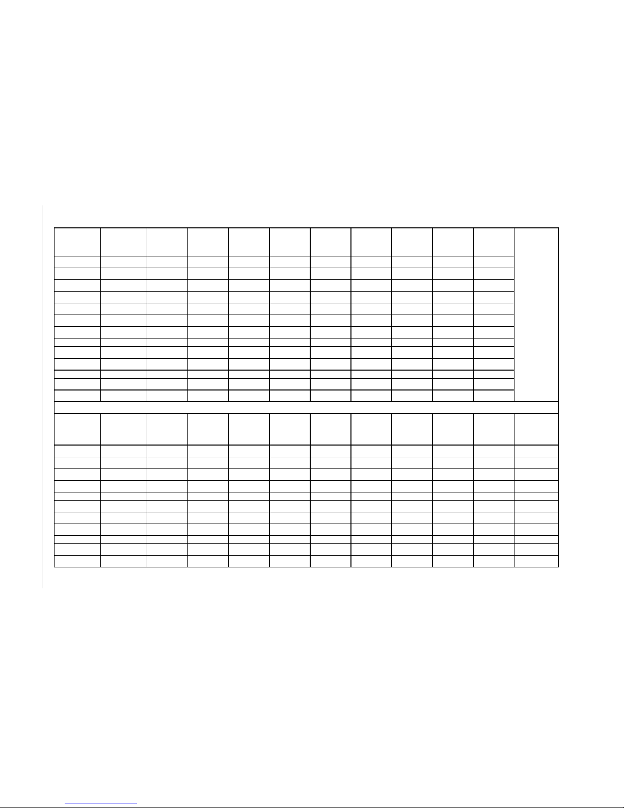
TABLE 3
OPTIONAL FIELD INSTALLED HEATER PACKAGES
ONLY TO BE USED WITH THE HEAT PUMP MODELS INDICATED
retaeH
egakcaP
ledoM
dnastloV
esahP24211HP14221HP10311HP0321HP16311HPB-16311HPC-16311HP6321HPB-6321HP
nmulocsihT
tfelneebsah
knalb
yllanoitnetni
50A-BP3HE1-802/042SANSAN SAA ANAN
80A-BP3HE1-802/042SANSAN SAA ANAN
01A-BP3HE1-802/042ANANS1 SS1 A 1 A 1 SAN
51A-BP3HE1-802/042ANANSAN SAA ANAN
50A-CP3HE1-802/042ANS ANSANANANSAN
01A-CP3HE1-802/042ANS ANANANANANANAN
51A-CP3HE1-802/042ANANANS2 ANANANS2 AN
90B-BP3HE3-802/042ANANA1 ANA1 S 1 A 1 ANS
51B-BP3HE3-802/042ANANA AN ASA ANS3
90C-BP3HE3-084ANANA1 ANA1 A 1 S 1 ANAN
51C-BP3HE3-084ANANAAN AAS ANAN
retaeH
egakcaP
ledoM
dnastloV
esahP22411HP2421HP18401HPB-18401HPC-18401HP18421HPB-18421HP0601HPB-0601HPC-0601HP
50A-BP5HE1-802/042 SSSAAS ANSAA
01A-BP5HE1-802/042S1 SS1 A 1 A 1 SANS1 A 1 A 1
51A-BP5HE1-802/042SS2 SAAS2 ANSAA
02A-BP5HE1-802/042ANAN SAA ANANSAA
90B-BP5HE3-802/042ANANA1 S 1 A 1 ANSA1 S 1 A 1
51B-BP5HE3-802/042ANAN ASA ANS3 AS A
81B-BP5HE3-802/042ANAN ASA ANANASA
90C-CP5HE3-084ANANA1 A 1 S 1 ANANA1 A 1 S 1
81C-CP5HE3-084ANAN AAS ANANAAS

Manual 2100-354
Page 7
j
Time delay fuses of HACR type circuit breakers must be used for 60 and smaller sizes. Standard fuses or circuit breakers are suitable for sizes 70 and
larger. 480V circuit breakers are not HACR type.
k
Based on wire suitable for 75 degree C. Other wiring materials must be rated for marked Minimum Circuit Ampacity or greater.
l
Based upon Table 250-95 of N.E.C. 1993. See electric data for basic heat pump for Circuit A wiring specification requirements.
NOTE: While this electrical data is presented as a guide, it is important to electrically connect properly sized
fuses and conductor wires in accordance with the national Electrical Code and all existing local codes.
TABLE 4
OPTIONAL FIELD INSTALLED ELECTRIC HEATER TABLE
.gkPretaeH
.oNledoM
stloVtinU
sesahP&
&WKretaeH
@yticapaC
stloV042
&WKretaeH
@yticapaC
stloV802
V802/042
retaeH
spmA
retaeH
lanretnI
esuF
BtiucriC
WKHUTBWKHUTB
.oN
dleiF
stiucriC
.niM
tiucriC
yticapmA
1
revO.xaM
tnerruC
noitcetorP
2
dleiF
rewoP
gniriW
3
dnuorG
eziSeriW
50A-BP3HE
80A-BP3HE
01A-BP3HE
51A-BP3HE
80A-CP3HE
01A-CP3HE
51A-CP3HE
1-802/042
1-802/042
1-802/042
1-802/042
1-802/042
1-802/042
1-802/042
5
8
01
51
5
01
51
001,71
003,72
001,43
002,15
001,71
001,43
002,15
57.3
00.6
05.7
52.11
57.3
05.7
52.11
008,21
005,02
000,62
004,83
008,21
000,62
004,83
1.81/8.02
8.82/3.33
2.63/6.14
1.45/5.26
1.81/8.02
2.63/6.14
1.45/5.26
06/03
06/03
1
1
1
1
1
1
1
32/62
63/24
64/35
86/97
32/62
84/35
86/97
52/03
04/54
05/06
07/08
52/03
05/06
07/08
01/01
01/01
8/6
4/4
01/01
8/6
4/4
01
01
01
8
01
01
8
50A-BP5HE
01A-BP5HE
51A-BP5HE
02A-BP5HE
1-802/042
1-802/042
1-802/042
1-802/042
5
01
51
02
001,71
001,43
002,15
002,86
57.3
05.7
52.11
00.51
008,21
000,62
004,83
002,15
1.81/8.02
2.63/6.14
1.45/5.26
1.27/2.38
06/03
06/06
1
1
1
1
32/62
64/35
86/97
19/401
52/03
05/06
07/08
001/011
01/01
8/6
4/4
3/2
01
01
8
6
90B-BP3HE
51B-BP3HE
3-802/042
3-802/042
9
51
007,03
002,15
57.6
52.11
000,32
004,83
7.81/7.12
2.13/2.63
1
1
42/82
93/64
52/03
04/05
01/01
8/8
01
01
90B-BP5HE
51B-BP5HE
81B-BP5HE
3-802/042
3-802/042
3-802/042
9
51
81
007,03
002,15
004,16
57.3
52.11
05.31
000,32
004,83
001,64
7.81/7.12
2.13/2.63
5.73/4.34
1
1
1
42/82
93/64
74/55
52/03
04/05
05/06
01/01
8/8
8/6
01
01
01
90C-BP3HE
51C-BP3HE
3-084
3-084
9
51
007,03
002,15
62.8
77.31
002,82
000,74
8.01
0.81
1
1
51
32
51
52
41
01
41
01
90C-BP5HE
51C-BP5HE
81C-BP5HE
3-084
3-084
3-084
9
51
81
007,03
002,15
004,16
62.8
77.31
35.61
002,82
000,74
004,65
8.01
0.81
7.12
1
1
1
51
32
82
51
52
03
41
01
01
41
01
01
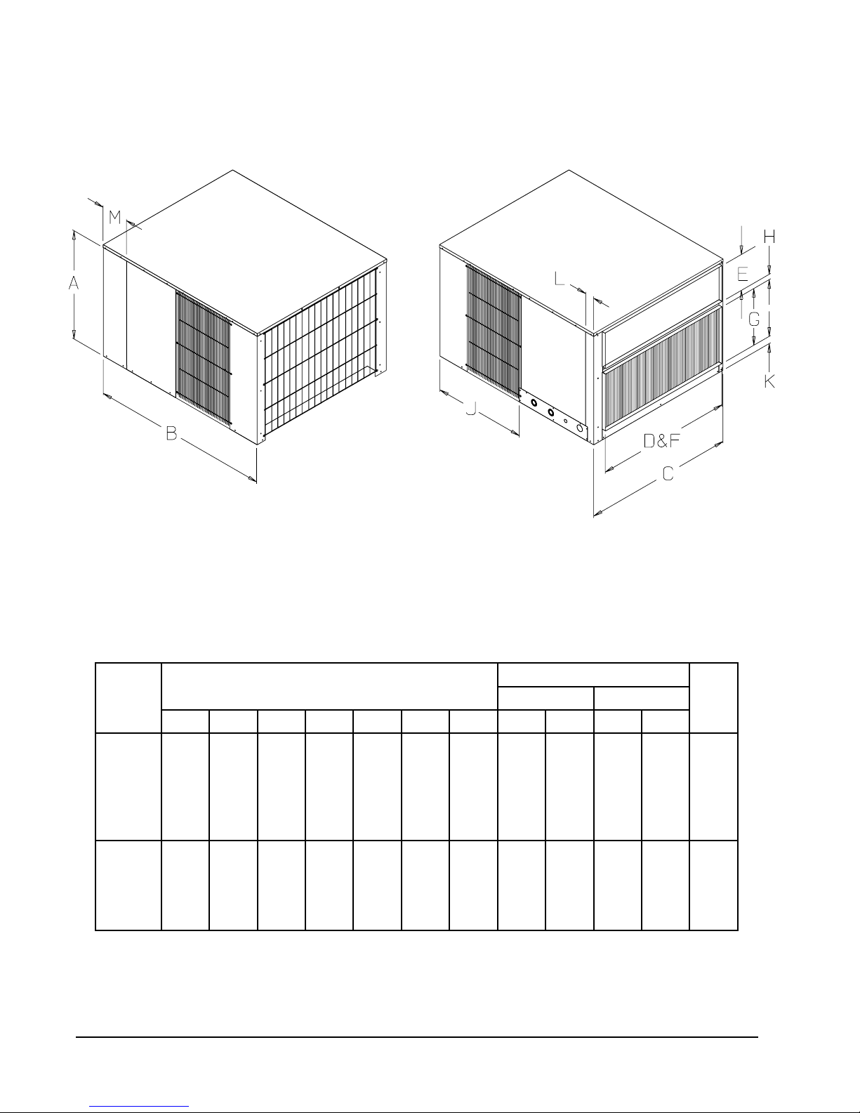
MIS-1305
FIGURE 1
UNIT DIMENSIONAL DRAWING
TABLE 5
DIMENSIONS OF UNIT
)sehcnI(gninepOtcuD
ledoM
.oN
ABCJKLMDEFG
)sehcnI(snoisnemiDtenibaClanimoN
egrahcsiDriAnruteR
H
4211HP
4221HP
0311HP
0321HP
4/1-4261/3-848/1-838/1-628/1-261/961/933633418/7
6311HP
6321HP
2411HP
2421HP
8411HP
4/1-130524623 4/3-261/9-7830183618/3-1
8421HP
0601HP
Manual 2100-354
Page 8

INSTALLATION
LOCATION
GENERAL
The unit must be located outside, or in a well ventilated
area. It must not be in the space being heated or cooled. A
sound absorbing material should be considered if the unit
is to be installed in such a position or location that might
cause transmission of sound or vibration to the living area
or adjacent buildings.
SLAB MOUNTING
In areas where winter temperatures DO NOT go below
32° F for periods over twelve hours, the unit may be slab
mounted at grade level. When installing unit at grade
level, install on a concrete slab at least four inches above
finished grade level. Slab should have a slope tolerance
away from the building structure of at lease 1/4 inch per
foot, while being level from side to side. This will prevent
ice buildup under the unit during defrost cycles. Place slab
in a location where runoff water from higher ground will
not collect around unit. See Figure 2.
A minimum of 18 inches should be provided between the
coil inlet and any building surfaces. Provide at least four
feet between coil outlet and any building wall, fences or
other vertical structures. Provide a minimum of three feet
clearance on the service access side of the unit. See
Figure 3
ROOF MOUNTING
When a unit is installed in areas where low ambient
temperatures or strong winter winds exist, it should be
placed so prevailing winter winds are not in direct line
with the heat pump coil. If this is not possible, a wind
barrier should be constructed. Place barrier 24 inches
from the coil inlet side of the unit and in the direction of
prevailing winds. Size barrier at least the same height and
width as the unit. This may be necessary on ground level
installations, also. See Figure 4.
WINTER INSTALLATION BELOW 32°F
In areas where winter conditions go below 32°F for
extended periods, the unit must be elevated above the
mounting surface to prevent snowfall or defrost ice
accumulation from interfering with the operation of the
unit. A minimum of twelve inch elevation is
recommended, while greater elevation may be required for
areas of high snow accumulation. Poured concrete, steel
framework, brick, cement block, etc., can be utilized to
construct a suitable raised mounting platform. See
Figure 5.
TYPICAL INSTALLATIONS
1.
ROOF MOUNTED
sturdy base on the roof of the building. Return air to
the unit is brought through a single return grille (grilles
with built-in filters are best since they enable easy
access for filter changing). Return air ducts are
attached to the lower section of the front panel.
Supply air is brought from the unit to attic duct work
or to a furred down hall. Supply air duct is attached to
the top of the front panel.
CAUTION: All outdoor duct work must be
thoroughly insulated and weatherproofed. All
attic duct work must be thoroughly insulated.
Two inch thick insulation with suitable vapor
barrier is recommended for both outdoor and
attic runs.
In roof top installation, as in all installations, the heat
pump must be level from side to side. However, the
unit should have a pitch along the length to assure
complete external drainage of precipitation and of
defrost condensate. See Figures 6 and 7, and Tables 6
and 7.
CRAWL SPACE
2.
space must be well insulated and provided with a
vapor barrier. In addition, the crawl space must be
thoroughly ventilated and provided with a good vapor
barrier as a ground cover. It is most desirable to install
the unit outdoors rather than inside the crawl space, so
that it will be readily accessible for service. In
addition, it is necessary to dispose of the condensate
from the outdoor coil on the heating cycle, and this is
virtually impossible with the unit installed inside the
crawl space.
SLAB MOUNTED AT GROUND LEVEL
3.
type installation is ideal for homes with a slab floor
construction where a roof mounted unit is not desired.
The supply and return duct work can be run through a
furred closet space.
THROUGH THE WALL
4.
requires a suitable framework to be fabricated capable
of withstanding the unit weight. Normally the unit will
be insulated so as to minimize supply and return duct
work.
– The unit is mounted on a
– Duct work installed in crawl
– This type installation
– This
Manual 2100-354
Page 9
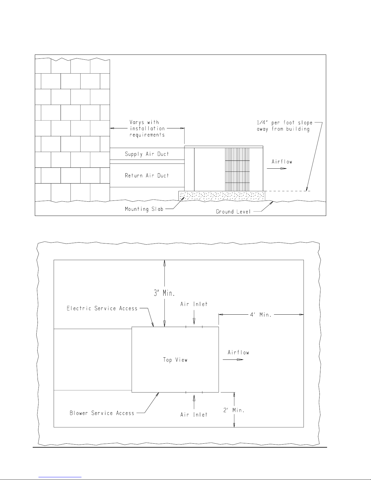
FIGURE 2
SLAB MOUNTING AT GROUND LEVEL
(Above 32°F Outside Temperature)
FIGURE 3
AIRFLOW AND SERVICE ACCESS CLEARANCES
MIS-1185
Manual 2100-354
Page 10
 Loading...